US11545843B2 - Battery charging apparatus and battery charging protection control method - Google Patents
Battery charging apparatus and battery charging protection control method Download PDFInfo
- Publication number
- US11545843B2 US11545843B2 US16/572,071 US201916572071A US11545843B2 US 11545843 B2 US11545843 B2 US 11545843B2 US 201916572071 A US201916572071 A US 201916572071A US 11545843 B2 US11545843 B2 US 11545843B2
- Authority
- US
- United States
- Prior art keywords
- output
- charging
- communication interface
- power adapter
- current
- Prior art date
- Legal status (The legal status is an assumption and is not a legal conclusion. Google has not performed a legal analysis and makes no representation as to the accuracy of the status listed.)
- Active, expires
Links
Images


Classifications
-
- H02J7/00304—
-
- H—ELECTRICITY
- H02—GENERATION; CONVERSION OR DISTRIBUTION OF ELECTRIC POWER
- H02J—ELECTRIC POWER NETWORKS; CIRCUIT ARRANGEMENTS OR SYSTEMS FOR SUPPLYING OR DISTRIBUTING ELECTRIC POWER; SYSTEMS FOR STORING ELECTRIC ENERGY
- H02J7/00—Circuit arrangements for charging or discharging batteries or for supplying loads from batteries
- H02J7/60—Circuit arrangements for charging or discharging batteries or for supplying loads from batteries including safety or protection arrangements
- H02J7/62—Circuit arrangements for charging or discharging batteries or for supplying loads from batteries including safety or protection arrangements against overcurrent
-
- H—ELECTRICITY
- H02—GENERATION; CONVERSION OR DISTRIBUTION OF ELECTRIC POWER
- H02J—ELECTRIC POWER NETWORKS; CIRCUIT ARRANGEMENTS OR SYSTEMS FOR SUPPLYING OR DISTRIBUTING ELECTRIC POWER; SYSTEMS FOR STORING ELECTRIC ENERGY
- H02J7/00—Circuit arrangements for charging or discharging batteries or for supplying loads from batteries
-
- H02J7/00308—
-
- H02J7/0045—
-
- H02J7/0068—
-
- H02J7/00718—
-
- H02J7/007184—
-
- H—ELECTRICITY
- H02—GENERATION; CONVERSION OR DISTRIBUTION OF ELECTRIC POWER
- H02J—ELECTRIC POWER NETWORKS; CIRCUIT ARRANGEMENTS OR SYSTEMS FOR SUPPLYING OR DISTRIBUTING ELECTRIC POWER; SYSTEMS FOR STORING ELECTRIC ENERGY
- H02J7/00—Circuit arrangements for charging or discharging batteries or for supplying loads from batteries
- H02J7/60—Circuit arrangements for charging or discharging batteries or for supplying loads from batteries including safety or protection arrangements
- H02J7/64—Circuit arrangements for charging or discharging batteries or for supplying loads from batteries including safety or protection arrangements against overvoltage
-
- H—ELECTRICITY
- H02—GENERATION; CONVERSION OR DISTRIBUTION OF ELECTRIC POWER
- H02J—ELECTRIC POWER NETWORKS; CIRCUIT ARRANGEMENTS OR SYSTEMS FOR SUPPLYING OR DISTRIBUTING ELECTRIC POWER; SYSTEMS FOR STORING ELECTRIC ENERGY
- H02J7/00—Circuit arrangements for charging or discharging batteries or for supplying loads from batteries
- H02J7/70—Circuit arrangements for charging or discharging batteries or for supplying loads from batteries characterised by the mechanical construction
- H02J7/751—Circuit arrangements for charging or discharging batteries or for supplying loads from batteries characterised by the mechanical construction concerning the insertion or the connection of the batteries
-
- H—ELECTRICITY
- H02—GENERATION; CONVERSION OR DISTRIBUTION OF ELECTRIC POWER
- H02J—ELECTRIC POWER NETWORKS; CIRCUIT ARRANGEMENTS OR SYSTEMS FOR SUPPLYING OR DISTRIBUTING ELECTRIC POWER; SYSTEMS FOR STORING ELECTRIC ENERGY
- H02J7/00—Circuit arrangements for charging or discharging batteries or for supplying loads from batteries
- H02J7/865—Battery or charger load switching, e.g. concurrent charging and load supply
-
- H—ELECTRICITY
- H02—GENERATION; CONVERSION OR DISTRIBUTION OF ELECTRIC POWER
- H02J—ELECTRIC POWER NETWORKS; CIRCUIT ARRANGEMENTS OR SYSTEMS FOR SUPPLYING OR DISTRIBUTING ELECTRIC POWER; SYSTEMS FOR STORING ELECTRIC ENERGY
- H02J7/00—Circuit arrangements for charging or discharging batteries or for supplying loads from batteries
- H02J7/90—Regulation of charging or discharging current or voltage
- H02J7/94—Regulation of charging or discharging current or voltage in response to battery current
- H02J7/953—Regulation of charging or discharging current or voltage in response to battery current in response to charge current gradient
-
- H—ELECTRICITY
- H02—GENERATION; CONVERSION OR DISTRIBUTION OF ELECTRIC POWER
- H02J—ELECTRIC POWER NETWORKS; CIRCUIT ARRANGEMENTS OR SYSTEMS FOR SUPPLYING OR DISTRIBUTING ELECTRIC POWER; SYSTEMS FOR STORING ELECTRIC ENERGY
- H02J7/00—Circuit arrangements for charging or discharging batteries or for supplying loads from batteries
- H02J7/90—Regulation of charging or discharging current or voltage
- H02J7/96—Regulation of charging or discharging current or voltage in response to battery voltage
- H02J7/963—Regulation of charging or discharging current or voltage in response to battery voltage in response to battery voltage gradient
-
- H02J7/00034—
-
- H02J7/00302—
-
- H—ELECTRICITY
- H02—GENERATION; CONVERSION OR DISTRIBUTION OF ELECTRIC POWER
- H02J—ELECTRIC POWER NETWORKS; CIRCUIT ARRANGEMENTS OR SYSTEMS FOR SUPPLYING OR DISTRIBUTING ELECTRIC POWER; SYSTEMS FOR STORING ELECTRIC ENERGY
- H02J7/00—Circuit arrangements for charging or discharging batteries or for supplying loads from batteries
- H02J7/40—Circuit arrangements for charging or discharging batteries or for supplying loads from batteries characterised by the exchange of charge or discharge related data
- H02J7/42—Circuit arrangements for charging or discharging batteries or for supplying loads from batteries characterised by the exchange of charge or discharge related data with electronic devices having internal batteries, e.g. mobile phones
-
- H—ELECTRICITY
- H02—GENERATION; CONVERSION OR DISTRIBUTION OF ELECTRIC POWER
- H02J—ELECTRIC POWER NETWORKS; CIRCUIT ARRANGEMENTS OR SYSTEMS FOR SUPPLYING OR DISTRIBUTING ELECTRIC POWER; SYSTEMS FOR STORING ELECTRIC ENERGY
- H02J7/00—Circuit arrangements for charging or discharging batteries or for supplying loads from batteries
- H02J7/60—Circuit arrangements for charging or discharging batteries or for supplying loads from batteries including safety or protection arrangements
- H02J7/61—Circuit arrangements for charging or discharging batteries or for supplying loads from batteries including safety or protection arrangements against overcharge
-
- Y—GENERAL TAGGING OF NEW TECHNOLOGICAL DEVELOPMENTS; GENERAL TAGGING OF CROSS-SECTIONAL TECHNOLOGIES SPANNING OVER SEVERAL SECTIONS OF THE IPC; TECHNICAL SUBJECTS COVERED BY FORMER USPC CROSS-REFERENCE ART COLLECTIONS [XRACs] AND DIGESTS
- Y02—TECHNOLOGIES OR APPLICATIONS FOR MITIGATION OR ADAPTATION AGAINST CLIMATE CHANGE
- Y02E—REDUCTION OF GREENHOUSE GAS [GHG] EMISSIONS, RELATED TO ENERGY GENERATION, TRANSMISSION OR DISTRIBUTION
- Y02E60/00—Enabling technologies; Technologies with a potential or indirect contribution to GHG emissions mitigation
- Y02E60/10—Energy storage using batteries
Definitions
- This disclosure relates to charging technical field, and particularly relates to a battery charging apparatus and a battery charging protection control method.
- a battery in an electronic device is generally charged by coupling a communication interface of the electronic device to an external power adapter.
- a charging current is increased in the related art for quick charging of the battery.
- the charging voltage and/or the charging current for the battery is too large in the charging process, the battery will be damaged because of an overvoltage charging and/or an overcurrent charging. Therefore, the above mentioned charging methods cannot realize an overvoltage protection and/or an overcurrent protection for the battery in the electronic device during a conventional charging or a quick charging.
- An objective of this disclosure is to provide a battery charging apparatus so as to solve the problem in the related art that overvoltage and/or overcurrent protection cannot be realized for a battery when a conventional charging or a quick charging is performed on the battery in an electronic device.
- a battery charging apparatus includes a power adapter and a charging control circuit, in which, the charging control circuit is built in an electronic device and coupled to a controller and a battery in the electronic device, the power adapter is coupled to a communication interface of the electronic device via a communication interface thereof, the battery is charged by the power adapter via the communication interface of the electronic device, and the charging control circuit performs data communication with the power adapter via the communication interface of the electronic device;
- the power adapter first determines whether an output voltage is greater than a voltage threshold and whether an output current is greater than a current threshold, if the output voltage is greater than the voltage threshold and/or the output current is greater than the current threshold, the power adapter sends a first charging stop command to the charging control circuit and automatically switches off direct current output, the charging control circuit drives the controller to switch off the communication interface of the electronic device according to the first charging stop command; if the output voltage is not greater than the voltage threshold, and the output current is not greater than the current threshold, the power adapter feeds back output voltage information and output current information to the charging control circuit, if the charging control circuit determines that the output voltage of the power adapter is greater than the voltage threshold and/or the output current of the power adapter is greater than the current threshold according to the output voltage information and the output current information, the charging control circuit feeds back a second charging stop command to the power adapter and drives the controller to switch off the communication interface of the electronic device, and the power
- Another objective of this disclosure is to provide a battery charging protection control method based on the above-described battery charging apparatus, the battery charging protection control method is executed as follows.
- the power adapter first determines whether an output voltage is greater than a voltage threshold, and determines whether an output current is greater than a current threshold.
- the power adapter determines that the output voltage is greater than the voltage threshold and/or the output current is greater than the current threshold, the power adapter sends a first charging stop command to the charging control circuit and switches off direct current output automatically, and the charging control circuit drives the controller to switch off the communication interface of the electronic device according to the first charging stop command.
- the power adapter determines that the output voltage is not greater than the voltage threshold and the output current is not greater than the current threshold, the power adapter feeds back output voltage information and output current information to the charging control circuit.
- the charging control circuit determines whether the output voltage of the power adapter is greater than the voltage threshold and whether the output current of the power adapter is greater than the current threshold according to the output voltage information and the output current information.
- the charging control circuit determines that the output voltage of the power adapter is greater than the voltage threshold and/or the output current of the power adapter is greater than the current threshold, the charging control circuit feeds back a second charging stop command to the power adapter and drives the controller to switch off the communication interface of the electronic device, and the power adapter switches off the direct current output according to the second charging stop command.
- the power adaptor determines whether the output voltage is greater than the voltage threshold and whether the output current is greater than the current threshold.
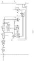
- FIG. 1 shows a schematic block diagram of a battery charging apparatus provided by an exemplary embodiment of this disclosure.
- FIG. 2 shows a flow chart for realizing a battery charging protection control method based on the battery charging apparatus shown in FIG. 1 .
- FIG. 3 shows a schematic block diagram of a power adapter in the battery charging apparatus shown in FIG. 1 .
- FIG. 4 shows an exemplary circuit of the power adapter shown in FIG. 3 .
- FIG. 5 shows an exemplary circuit of a charging control circuit in the battery charging apparatus shown in FIG. 1 .
- FIG. 6 shows another exemplary circuit of a charging control circuit in the battery charging apparatus shown in FIG. 1 .
- FIG. 1 shows a schematic block diagram of a battery charging apparatus provided by an exemplary embodiment of this disclosure. For description, only parts related to the exemplary embodiment of this disclosure are shown, and detailed description thereof is as follows.
- the battery charging apparatus includes a power adapter 100 and a charging control circuit 200 , the charging control circuit 200 is built in an electronic device and coupled to a controller 300 and a battery 400 in the electronic device, the power adapter 200 is coupled to a communication interface 20 of the electronic device via the communication interface 10 thereof, the battery 400 is charged by the power adapter 100 via the communication interface 20 of the electronic device, and the charging control circuit 200 performs data communication with the power adapter 100 via the communication interface 20 of the electronic device.
- the power adapter 100 first determines whether an output voltage is greater than a voltage threshold and whether an output current is greater than a current threshold, if the output voltage of the power adapter 100 is greater than the voltage threshold and/or the output current of the power adapter 100 is greater than the current threshold, the power adapter 100 sends a first charging stop command to the charging control circuit 200 and switches off the direct current automatically, the charging control circuit 200 drives the controller 300 to switch off the communication interface 20 of the electronic device according to the first charging stop command; if the output voltage of the power adapter 100 is not greater than the voltage threshold, and the output current of the power adapter 100 is not greater than the current threshold, the power adapter 100 feeds back output voltage information and output current information to the charging control circuit 200 , if the charging control circuit 200 determines that the output voltage of the power adapter 100 is greater than the voltage threshold and/or the output current of the power adapter 100 is greater than the current threshold according to the output voltage information and the output current information
- the present disclosure further provides a battery charging protection control method, as shown in FIG. 2 , the battery charging protection control method includes following blocks.
- the power adapter 100 first determines whether an output voltage is greater than a voltage threshold, and determines whether an output current is greater than a current threshold. If the power adapter 100 determines that the output voltage is greater than the voltage threshold and/or the output current is greater than the current threshold, block S 2 is executed, and if the power adapter 100 determines that the output voltage is not greater than the voltage threshold and the output current is not greater than the current threshold, block S 4 is executed.
- the power adapter 100 sends a first charging stop command to the charging control circuit 200 and switches off the direct current output automatically.
- the charging control circuit 200 drives the controller 300 to switch off the communication interface 20 of the electronic device according to the first charging stop command.
- the power adapter 100 feeds back output voltage information and output current information to the charging control circuit 200 .
- the charging control circuit 200 determines whether the output voltage of the power adapter 100 is greater than the voltage threshold and whether the output current of the power adapter 100 is greater than the current threshold according to the output voltage information and the output current information. If the charging control circuit 200 determines that the output voltage of the power adapter 100 is greater than the voltage threshold and/or the output current of the power adapter 100 is greater than the current threshold, block S 6 is executed, and if the charging control circuit 200 determines that the output voltage of the power adapter 100 is not greater than the voltage threshold and the output current of the power adapter 100 is not greater than the current threshold, block S 1 is executed.
- the charging control circuit 200 feeds back a second charging stop command to the power adapter 100 and drives the controller 300 to switch off the communication interface 20 of the electronic device.
- the voltage threshold and the current threshold are a preset maximum voltage value and a preset maximum current value respectively.
- block S 4 is executed as follows.
- the charging control circuit 200 sends a charging parameter acquiring request to the power adapter 100 .
- the power adapter 100 feeds back the output voltage information and the output current information to the charging control circuit 200 according to the charging parameter acquiring request.
- block S 3 is specifically performed as follows.
- the charging control circuit 200 stops introducing the direct current from the power adapter 100 to charge the battery 400 , and drives the controller 300 to switch off the communication interface 20 of the electronic device, according to the first charging stop command.
- block S 4 is executed as follows.
- the charging control circuit 200 feeds back the second charging stop command to the power adapter 100 .
- the charging control circuit 200 stops introducing the direct current from the power adapter 100 to charge the battery 400 , and drives the controller 300 to switch off the communication interface 20 of the electronic device.
- FIG. 3 shows a schematic block diagram thereof. For description, it only shows the parts related to the exemplary embodiment of this disclosure, which is detailed as follows.
- the power adapter 100 includes an EMI filter circuit 101 , a high-voltage rectifier and filter circuit 102 , an isolation transformer 103 , an output filter circuit 104 , and a voltage tracking and control circuit 105 ; after an electromagnetic interference filter is performed by the EMI filter circuit on mains supply, a rectifying and filtering process is performed by the high-voltage rectifier and filter circuit for outputting a high-voltage direct current, the high-voltage direct current is output to the output filter circuit after an electrical isolation through the isolation transformer so as to charge the battery after a filtering process, the voltage tracking and control circuit regulates an output voltage of the isolation transformer according to an output voltage of the output filter circuit.
- the power adapter 100 further includes a power circuit 106 , a main control circuit 107 , a potential regulation circuit 108 , a current detection circuit 109 , a voltage detection circuit 110 and an output switch circuit 111 .
- An input terminal of the power circuit 106 is coupled to a secondary terminal of the isolation transformer 103 ; a power terminal of the main control circuit 107 , a power terminal of the potential regulation circuit 108 , and a power terminal of the current detection circuit 109 are jointly coupled to an output terminal of the power circuit 108 , a high-potential terminal of the main control circuit 107 and a high-potential terminal of the potential regulation circuit 108 are both coupled to a positive output terminal of the output filter circuit 104 , a potential regulation terminal of the potential regulation circuit 108 is coupled to the voltage tracking and control circuit 105 ; a direct current input terminal of the current detection circuit 109 is coupled to a positive output terminal of the output filter circuit 104 ; a current detection feedback terminal of the current detection circuit 109 is coupled to a current detection terminal of the main control circuit 107 ; a clock output terminal and a data output terminal of the main control circuit 107 are coupled to a clock input terminal and a data input terminal of the potential regulation circuit 108 ; a first detection
- the power circuit 106 obtains power from the isolation transformer 103 and provides power to the main control circuit 107 , the potential regulation circuit 108 , and the current detection circuit 109 ; when a quick charging is performed on the battery 400 in the electronic device, the potential regulation circuit 108 drives the voltage tracking and control circuit 105 to regulate the output voltage of the isolation transformer 103 according to a control signal sent by the main control circuit 107 so as to perform the quick charging on the battery; the current detection circuit 109 and the voltage detection circuit 110 respectively detects the output current and the output voltage of the power adapter 100 , and correspondingly feeds back a current detection signal and a voltage detection signal to the main control circuit 107 ; the output switch circuit 111 switches on or off the direct current output of the power adapter 100 according to a switch control signal sent by the main control circuit 107 .
- the main control circuit 107 determines whether the output current of the power adapter 100 is greater than the current threshold according to the current detection signal, and determines whether the output voltage of the power adapter 100 is greater than the voltage threshold according to the voltage detection signal, if the output voltage of the power adapter 100 is greater than the voltage threshold and/or the output current of the power adapter 100 is greater than the current threshold, the main control circuit 107 sends the first charging stop command to the charging control circuit 200 and controls the output switch circuit 111 to switch off the direct current output of the power adapter 100 , and the charging control circuit 200 drives the controller 300 to switch off the communication interface 20 of the electronic device according to the first charging stop command; if the output voltage of the power adapter 100 is not greater than the voltage threshold, and the output current of the power adapter 100 is not greater than the current threshold, the main control circuit 107 feeds back the output voltage information and the output current information to the charging control circuit 200 according to the voltage detection signal and the current detection signal,
- the main control circuit 107 feeds back the output voltage information and the output current information to the charging control circuit 200 according to the voltage detection signal and the current detection signal as follows.
- the charging control circuit 200 sends a charging parameter acquiring request to the main control circuit 107 , and the main control circuit 107 feeds back the output voltage information and the output current information to the charging control circuit 200 according to the charging parameter acquiring request.
- the charging control circuit 200 When a quick charging is performed on the battery 400 , since the charging control circuit 200 will introduce the direct current from the power adapter 100 to charge the battery 400 so as to increase charging current on the battery for realizing a quick charging on the battery, the charging control circuit 200 also needs to stop introducing the direct current from the power adapter 100 in addition to driving the controller 300 to switch off the communication interface 20 of the electronic device if overvoltage and/or overcurrent occur on the output of the power adapter 100 . Therefore, the charging control circuit 200 specifically drives the controller 300 to switch off the communication interface 20 of the electronic device according to the first charging stop command as follows.
- the charging control circuit 200 stops introducing the direct current from the power adapter 100 to charge the battery 400 , and drives the controller 300 to switch off the communication interface 20 of the electronic device, according to the first charging stop command.
- the charging control circuit 200 feeds back the second charging stop command to the main control circuit 107 as follows.
- the charging control circuit 200 feeds back the second charging stop command to the main control circuit 107 ; the charging control circuit 200 stops introducing the direct current from the power adapter 100 to charge the battery 400 , and drives the controller 300 to switch off the communication interface 20 of the electronic device.
- FIG. 4 shows an exemplary circuit of the power adapter 100 .
- FIG. 4 shows the parts related to the exemplary embodiment of this disclosure, which is detailed as follows.
- the power circuit 106 includes: a first capacitor C 1 , a voltage stabilizing chip U 1 , a second capacitor C 2 , a first inductor L 1 , a second inductor L 2 , a first diode D 1 , a second diode D 2 , a third capacitor C 3 , a first resistor R 1 and a second resistor R 2 .
- a junction of a first terminal of the first capacitor C 1 , and an input power pin Vin and an enable pin EN of the voltage stabilizing chip U 1 is configured as the input terminal of the power circuit 106 , a second terminal of the first capacitor C 1 and a ground pin GND of the voltage stabilizing chip U 1 are jointly grounded, a switch pin SW of the voltage stabilizing chip U 1 and a first terminal of the second capacitor C 2 are jointly coupled to a first terminal of first inductor L 1 , an internal switch pin BOOST of the voltage stabilizing chip U 1 and a second terminal of the second capacitor C 2 are jointly coupled to a cathode of the first diode D 1 , an voltage feedback pin FB of the voltage stabilizing chip U 1 is coupled to a first terminal of the first resistor R 1 and a first terminal of the second resistor R 2 , a second terminal of the first inductor L 1 and a cathode of the second diode D 2 are jointly coupled to a first terminal of the second inductor L 2 , a junction of
- the power circuit 106 performs the voltage conversion processing on the voltage at the secondary terminal of the isolation transformer 103 by using voltage stabilizing chip U 1 as the core, and outputs +3.3V voltage for supplying power to the main control circuit 107 , the potential regulation circuit 108 and the current detection circuit 109 .
- the voltage stabilizing chip U 1 may be an MCP16301 buck DC/DC converter.
- the main control circuit 107 includes: a main control chip U 2 , a third resistor R 3 , a reference voltage chip U 3 , a fourth resistor R 4 , a fifth resistor R 5 , a fourth capacitor C 4 , a sixth resistor R 6 , a seventh resistor R 7 , a first NMOS transistor Q 1 , an eighth resistor R 8 , a ninth resistor R 9 , a tenth resistor R 10 , an eleventh resistor R 11 , a twelfth resistor R 12 , a thirteenth resistor R 13 and a fourteenth resistor R 14 .
- a power pin VDD of the main control chip U 3 is configured as the power terminal of the main control circuit 107 , a ground pin VSS of the main control chip U 3 is grounded, a first input/output pin RA 0 of the main control chip U 3 is suspended, a first terminal of the third resistor R 3 is coupled to the power pin VDD of the main control chip U 3 , a second terminal of the third resistor R 3 and a first terminal of the fourth resistor R 4 are jointly coupled to a positive pole CATHODE of the reference voltage chip U 3 , a negative pole ANODE of the reference voltage chip U 3 is grounded, a vacant pin NC of the reference voltage chip U 3 is suspended, a second terminal of the fourth resistor R 4 is coupled to a second input/output pin RA 1 of the main control chip U 2 , a third input/output pin RA 2 of the main control chip U 2 is configured as the current detection terminal of the main control circuit 107 , a fourth input/output pin RA 3 of the main control chip U
- a second terminal of the fourth capacitor C 4 is grounded.
- a fifth input/output pin RA 4 of the main control chip U 2 is configured as the switch control terminal of the main control circuit 107 .
- a sixth input/output pin RA 5 of the main control chip U 2 is coupled to a first terminal of the sixth resistor R 6 .
- a second terminal of the sixth resistor R 6 and a gate electrode of the first NMOS transistor Q 1 are jointly coupled to a first terminal of seventh resistor R 7 .
- a second terminal of the seventh resistor R 7 and a source electrode of a first NMOS transistor Q 1 are jointly grounded.
- a drain electrode of the first NMOS transistor Q 1 is coupled to a first terminal of the eighth resistor R 8 .
- a second terminal of the eighth resistor R 8 is configured as the high-potential terminal of the main control circuit 107 .
- a seventh input/output pin RC 0 and an eighth input/output pin RC 1 of the main control chip U 2 are configured as the clock output terminal and the data output terminal of the main control circuit 107 respectively.
- a tenth input/output pin RC 3 and a ninth input/output pin RC 2 of the main control chip U 2 are configured as the first voltage detection terminal and the second voltage detection terminal of the main control circuit 107 respectively.
- An eleventh input/output pin RC 4 and a twelfth input/output pin RC 5 of the main control chip U 2 are coupled to a first terminal of the ninth resistor R 9 and a first terminal of the tenth resistor R 10 respectively.
- a first terminal of an eleventh resistor R 11 and a first terminal of the twelfth resistor R 12 are coupled to a second terminal of the ninth resistor R 9 and a second terminal of the tenth resistor R 10 respectively.
- a second terminal of the eleventh resistor R 11 and a second terminal of the twelfth resistor R 12 are jointly grounded.
- a first terminal of the thirteenth resistor R 13 and a first terminal of the fourteenth resistor R 14 are coupled to a second terminal of the ninth resistor R 9 and the second terminal of tenth resistor R 10 respectively.
- a second terminal of the thirteenth resistor R 13 and a second terminal of the fourteenth resistor R 14 are jointly coupled to the power pin VDD of the main control chip U 2 .
- the second terminal of ninth resistor R 9 and the second terminal of the tenth resistor R 10 are configured as the first communication terminal and the second communication terminal of the main control circuit 107 respectively.
- the main control chip U 2 may be a PIC12LF1822, PIC12F1822, PIC16LF1823 or PIC16F1823 single chip microcomputer
- reference voltage chip U 3 may be an LM4040 voltage reference device.
- the potential regulation circuit 108 includes: a fifteenth resistor R 15 , a sixteenth resistor R 16 , a digital potentiometer U 4 , a seventeenth resistor R 17 , an eighteenth resistor R 18 , a fifth capacitor C 5 , a sixth capacitor C 6 and a nineteenth resistor R 19 .
- a junction of a first terminal of fifteenth resistor R 15 , a first terminal of sixteenth resistor R 16 , a power pin VDD of the digital potentiometer U 4 and a first terminal of the fifth capacitor C 5 is configured as the power terminal of the potential regulation circuit 108 .
- a second terminal of the fifth capacitor C 5 , a first terminal of the sixth capacitor C 6 , a ground pin VSS of the digital potentiometer U 4 and a first terminal of the seventeenth resistor R 17 are jointly grounded.
- a second terminal of the sixth capacitor C 6 is coupled to the power pin VDD of the digital potentiometer U 4 .
- a junction of a second terminal of the fifteenth resistor R 15 and a serial data pin SDA of the digital potentiometer U 4 is configured as the data input terminal of the potential regulation circuit 108 .
- a junction of a second terminal of the sixteenth resistor R 16 and a clock input pin SCL of the digital potentiometer U 4 is configured as the clock input terminal of the potential regulation circuit 108 .
- An address zero pin AO of the digital potentiometer U 4 is grounded.
- a first potential wiring pin P 0 A of the digital potentiometer U 4 and a first terminal of eighteenth resistor R 18 are jointly coupled to a second terminal of the seventeenth resistor R 17 .
- a second terminal of the eighteenth resistor R 18 and a second potential wiring pin P 0 B of the digital potentiometer U 4 are jointly coupled to a first terminal of nineteenth resistor R 19 .
- a second terminal of the nineteenth resistor R 19 is configured as the high-potential terminal of the potential regulation circuit 108 .
- a potential tap pin P 0 W of digital potentiometer U 4 is configured as the potential regulation terminal of the potential regulation circuit 108 .
- the digital potentiometer U 4 adjusts an internal slide rheostat according to the clock signal and the data signal output from the main control chip U 2 so as to change the potential at the tap terminal of the internal slide rheostat (i.e., the potential tap pin P 0 W of the digital potentiometer U 4 ), such that the voltage tracking and control circuit 104 adjusts the output voltage of the isolation transformer 103 by following the potential change.
- the digital potentiometer U 4 may be an MCP45X1 digital potentiometer.
- the current detection circuit 109 includes: a twentieth resistor R 20 , a twenty-first resistor R 21 , a twenty-second resistor R 22 , a seventh capacitor C 7 , an eighth capacitor C 8 , a current detection chip U 5 , a twenty-third resistor R 23 , a ninth capacitor C 9 , a tenth capacitor C 10 and a twenty-fourth resistor R 24 .
- a first terminal and a second terminal of twentieth resistor R 20 are configured as the direct current input terminal and the direct current output terminal of current detection circuit 109 respectively, a first terminal of the twenty-first resistor R 21 and a first terminal of the twenty-second resistor R 22 are coupled to the first terminal and the second terminal of twentieth resistor R 20 respectively, a second terminal of the twenty-first resistor R 21 and a first terminal of seventh capacitor C 7 are jointly coupled to a positive input pin IN+ of the current detection chip U 5 , a second terminal of the twenty-second resistor R 22 and a first terminal of the eighth capacitor C 8 are jointly coupled to a negative input pin IN ⁇ of the current detection chip U 5 , a junction of a power pin V+ of the current detection chip U 5 and a first terminal of the ninth capacitor C 9 is configured as the power terminal of the current detection circuit 109 , a vacant pin NC of the current detection chip U 5 is suspended, an output pin OUT of the current detection chip U 5 is coupled to a first terminal of the twenty-third resistor R 23
- the twentieth resistor R 20 samples the output current of the output filter circuit 104 (i.e., the output current of the power adapter 100 ). Then, the current detection chip U 5 outputs a current detection signal to the main control chip U 2 according to the voltage across two terminals of the twentieth resistor R 20 , in which the current detection chip U 5 may be an INA286 current shunt monitor.
- the voltage detection circuit 110 includes: a twenty-fifth resistor R 25 , a twenty-sixth resistor R 26 , an eleventh capacitor C 11 , a twelfth capacitor C 12 , a twenty-seventh resistor R 27 and a twenty-eighth resistor R 28 .
- a first terminal of the twenty-fifth resistor R 25 is configured as the first detection terminal of the voltage detection circuit 110 , a junction of a second terminal of the twenty-fifth resistor R 25 , a first terminal of the twenty-sixth resistor R 26 and a first terminal of the eleventh capacitor C 11 is configured as the second output terminal of the voltage detection circuit 110 , a second terminal of the twenty-sixth resistor R 26 is configured as the second detection terminal of the voltage detection circuit 110 , a second terminal of eleventh capacitor C 11 , a first terminal of the twelfth capacitor C 12 and a first terminal of the twenty-seventh resistor R 27 are jointly coupled to a second terminal of the twenty-sixth resistor R 26 , a junction of a second terminal of the twelfth capacitor C 12 , a second terminal of the twenty-seventh resistor R 27 and a first terminal of the twenty-eighth resistor R 28 is configured as the first output terminal of the voltage detection circuit 110 , and a
- the output switch circuit 111 includes: a twenty-ninth resistor R 29 , a thirtieth resistor R 30 , a thirteenth capacitor C 13 , a thirty-first resistor R 31 , a first NPN triode N 1 , a thirty-second resistor R 32 , a second NPN triode N 2 , a third diode D 3 , a voltage stabilizing diode ZD, a thirty-third resistor R 33 , a thirty-fourth resistor R 34 , a thirty-fifth resistor R 35 , a second NMOS transistor Q 2 and a third NMOS transistor Q 3 .
- a first terminal of the twenty-ninth resistor R 29 is configured as the controlled terminal of the output switch circuit 111
- a second terminal of the twenty-ninth resistor R 29 and a first terminal of the thirtieth resistor R 30 are jointly coupled to a base electrode of the first NPN triode N 1
- a first terminal of the thirty-first resistor R 31 and a first terminal of the thirty-second resistor R 32 are jointly coupled to a cathode of the third diode D 3
- an anode of the third diode D 3 is configured as the power terminal of the output switch circuit 111
- a second terminal of the thirty-first resistor R 31 and a base electrode of the second NPN triode N 2 are jointly coupled to a collector electrode of the first NPN triode N 1
- a second terminal of the thirty-second resistor R 32 a cathode of the voltage stabilizing diode ZD and a first terminal of the thirty-third resistor R
- FIG. 5 shows an exemplary circuit of the charging control circuit 200 .
- FIG. 5 shows an exemplary circuit of the charging control circuit 200 .
- it only shows parts related to the exemplary embodiment of this disclosure, which is detailed as follows.
- the charging control circuit 200 includes: a battery connector J 1 , a main controller U 6 , a sixteenth capacitor C 16 , a thirty-sixth resistor R 36 , a thirty-seventh resistor R 37 , a fourteenth capacitor C 14 , a first Schottky diode SD 1 , a second Schottky diode SD 2 , a fifteenth capacitor C 15 , a thirty-eighth resistor R 38 , a thirty-ninth resistor R 39 , a fortieth resistor R 40 , a third NPN triode N 3 , a fourth NMOS transistor Q 4 and a fifth NMOS transistor Q 5 .
- the battery connector J 1 is coupled to multiple electrodes of the battery 300 , a first pin 5 A- 1 and a second pin 5 A- 2 of the battery connector J 1 are jointly grounded, a first ground pin GND 1 and a second ground pin GND 2 of the battery connector J 1 are jointly grounded, a first input/output pin RA 0 of the main controller U 6 is coupled to a seventh pin 5 A- 3 and an eighth pin 5 A- 4 of the battery connector J 1 , a second input/output pin RA 1 , a seventh input/output pin RC 0 , an eighth input/output pin RC 1 and a ninth input/output pin RC 2 of the main controller U 6 are coupled to a sixth pin 2 A- 4 , a fifth pin 2 A- 3 , a fourth pin 2 A- 2 and a third pin 2 A- 1 of the battery connector J 1 respectively, an analog ground pin VSS and a ground pin GND of the main controller U 6 are both grounded, a first vacant pin NC 0 and a second
- the main controller U 6 may specifically be a PIC12LF1501, PIC12F1501, PIC16LF1503, PIC16F1503, PIC16LF1507, PIC16F1507, PIC16LF1508, PIC16F1508, PIC16LF1509 or PIC16F1509 single chip microcomputer.
- the main controller U 6 When a quick charging is performed on the battery 400 , the main controller U 6 outputs a high level via its fifth input/output pin RA 4 for driving the fourth NMOS transistor Q 4 and the fifth NMOS transistor Q 5 to switch on, and controls the third NPN triode N 3 to switch off by outputting a low level via its tenth input/output pin RC 3 .
- the direct current introduced by the fourth NMOS transistor Q 4 and the fifth NMOS transistor Q 5 can further increase the current charging the battery 400 , thus enabling the quick charging to the battery 400 .
- the main controller U 6 controls the fourth NMOS transistor Q 4 and the fifth NMOS transistor Q 5 to turn off by outputting the low level via its fifth input/output pin RA 4 , and controls the third NPN triode N 3 to turn on by outputting the high level via its tenth input/output pin RC 3 .
- the main controller U 6 performs the data communication with the electronic device via its fourth input/output Pin RA 3 and eleventh input/output Pin RC 4 .
- the main controller U 6 can transmit the voltage and electric quantity information of the battery 400 to the controller 300 of the electronic device, and can also determine whether the quick charging process for the battery 400 has been completed according to the voltage of battery 400 . If the quick charging process for the battery 400 has been completed, the main controller U 6 may feed back a quick charging stop command to notify the electronic device to switch to the conventional charge mode from the quick charging mode.
- the main controller U 6 detects the voltage of the battery 400 via the battery connector J 1 , and feeds back a charging termination command to notify the controller 300 to switch off the communication interface 20 of the electronic device, so as to terminate the charge process for the battery 400 .
- the controller 300 of the electronic device may, in the case of abnormal temperature, inform the main controller U 6 to switch off the fourth NMOS transistor Q 4 and the fifth NMOS transistor Q 5 for stopping the quick charging to the battery 400 , and meanwhile the electronic device may switch to the conventional charge mode from the quick charging mode.
- the power line VBUS and the ground line GND of the communication interface 10 of the power adapter 100 are coupled to the ground line GND and the power line VBUS of the communication interface 20 of the electronic device respectively (i.e., the power line VBUS and the ground line GND of the communication interface 10 of power adapter 100 are coupled to the ground terminal of the charging control circuit 200 and the source electrode of the fifth NMOS transistor Q 5 respectively), which means that the communication interface 10 of the power adapter 100 is reversely coupled to the communication interface 20 of the electronic device, direct current is coupled to the ground terminal of charging control circuit 200 , and the source electrode of fifth NMOS transistor Q 5 is grounded.
- FIG. 1 In order to prevent any damage to the components, as shown in FIG.
- the charging control circuit 200 may further include a sixth NMOS transistor Q 6 , a seventh NMOS transistor Q 7 and a forty-first resistor R 41 .
- a source electrode of the sixth NMOS transistor Q 6 is coupled to a source electrode of the fifth NMOS transistor Q 5 .
- a drain electrode of the sixth NMOS transistor Q 6 is coupled to a drain electrode of the seventh NMOS transistor Q 7 .
- a source electrode of the seventh NMOS transistor Q 7 is coupled to the collector electrode of the third NPN triode N 3 .
- a gate electrode of the sixth NMOS transistor Q 6 and a gate electrode of the seventh NMOS transistor Q 7 are jointly coupled to a first terminal of the forty-first resistor R 41 .
- a second terminal of the forty-first resistor R 41 is grounded.
- direct current is coupled to the second terminal of the forty-first resistor R 41 via the ground for driving the sixth NMOS transistor Q 6 and the seventh NMOS transistor Q 7 to switch off, which prevents the direct current that flows into the charging control circuit 200 from the ground from forming a loop, thereby protecting components in the charging control circuit 200 from any damage.
- embodiments of the present disclosure adopts the battery charging apparatus including the power adapter 100 and the charging control circuit 200 to perform a charging control on the battery 400 in the electronic device.
- the power adapter 100 performs a data communication with the charging control circuit 200 , and when the power adapter 100 determines that overvoltage and/or overcurrent occurs in the direct current output via the communication interface 10 of the power adapter 100 , the power adapter 100 notifies the charging control circuit 200 to drive the controller 300 in the electronic device to switch off the communication interface 20 of the electronic device and switches off the direct current output automatically; when the charging control circuit 200 determines that overvoltage and/or overcurrent occurs upon receiving output voltage and output current of the power adapter 100 , the charging control circuit 200 notifies the power adapter 100 to switch off the direct current output and drives the controller 300 in the electronic device to switch off the communication interface 20 of the electronic device. In this way, overvoltage and/or overcurrent protection of the battery 400 is achieved when overvoltage
Landscapes
- Engineering & Computer Science (AREA)
- Power Engineering (AREA)
- Charge And Discharge Circuits For Batteries Or The Like (AREA)
- Secondary Cells (AREA)
Abstract
Description
Claims (17)
Priority Applications (1)
| Application Number | Priority Date | Filing Date | Title |
|---|---|---|---|
| US16/572,071 US11545843B2 (en) | 2014-01-28 | 2019-09-16 | Battery charging apparatus and battery charging protection control method |
Applications Claiming Priority (5)
| Application Number | Priority Date | Filing Date | Title |
|---|---|---|---|
| CN201410043218.5A CN103762691B (en) | 2014-01-28 | 2014-01-28 | Battery charger and cell charge protection control method |
| CN201410043218.5 | 2014-01-28 | ||
| PCT/CN2014/077474 WO2015113344A1 (en) | 2014-01-28 | 2014-05-14 | Battery charging apparatus and battery charging protection control method |
| US201615115251A | 2016-07-28 | 2016-07-28 | |
| US16/572,071 US11545843B2 (en) | 2014-01-28 | 2019-09-16 | Battery charging apparatus and battery charging protection control method |
Related Parent Applications (2)
| Application Number | Title | Priority Date | Filing Date |
|---|---|---|---|
| US15/115,251 Continuation US10461561B2 (en) | 2014-01-28 | 2014-05-14 | Battery charging apparatus and battery charging protection control method |
| PCT/CN2014/077474 Continuation WO2015113344A1 (en) | 2014-01-28 | 2014-05-14 | Battery charging apparatus and battery charging protection control method |
Publications (2)
| Publication Number | Publication Date |
|---|---|
| US20200014232A1 US20200014232A1 (en) | 2020-01-09 |
| US11545843B2 true US11545843B2 (en) | 2023-01-03 |
Family
ID=50529880
Family Applications (2)
| Application Number | Title | Priority Date | Filing Date |
|---|---|---|---|
| US15/115,251 Active US10461561B2 (en) | 2014-01-28 | 2014-05-14 | Battery charging apparatus and battery charging protection control method |
| US16/572,071 Active 2035-06-29 US11545843B2 (en) | 2014-01-28 | 2019-09-16 | Battery charging apparatus and battery charging protection control method |
Family Applications Before (1)
| Application Number | Title | Priority Date | Filing Date |
|---|---|---|---|
| US15/115,251 Active US10461561B2 (en) | 2014-01-28 | 2014-05-14 | Battery charging apparatus and battery charging protection control method |
Country Status (11)
| Country | Link |
|---|---|
| US (2) | US10461561B2 (en) |
| EP (2) | EP3386067B1 (en) |
| JP (2) | JP6243052B2 (en) |
| KR (2) | KR101996776B1 (en) |
| CN (1) | CN103762691B (en) |
| DK (1) | DK3101755T3 (en) |
| ES (2) | ES2737374T3 (en) |
| HU (1) | HUE039610T2 (en) |
| PL (1) | PL3101755T3 (en) |
| PT (1) | PT3101755T (en) |
| WO (1) | WO2015113344A1 (en) |
Cited By (1)
| Publication number | Priority date | Publication date | Assignee | Title |
|---|---|---|---|---|
| US12541242B2 (en) | 2021-01-11 | 2026-02-03 | Samsung Electronics Co., Ltd. | Electronic device and method for controlling electronic device |
Families Citing this family (52)
| Publication number | Priority date | Publication date | Assignee | Title |
|---|---|---|---|---|
| CN106329688B (en) * | 2014-01-28 | 2019-09-27 | Oppo广东移动通信有限公司 | Electronic equipment and its power adapter |
| CN103779907B (en) | 2014-01-28 | 2016-11-23 | 广东欧珀移动通信有限公司 | Terminal and battery charging control device and method thereof |
| PH12016501486B1 (en) * | 2014-01-28 | 2024-01-05 | Guangdong Oppo Mobile Telecommunications Corp Ltd | Terminal, power adapter and method for handling charging anomaly |
| CN103762691B (en) * | 2014-01-28 | 2015-12-23 | 广东欧珀移动通信有限公司 | Battery charger and cell charge protection control method |
| CN105098862A (en) * | 2014-05-19 | 2015-11-25 | 中兴通讯股份有限公司 | Charging control method, charging control device and charging control terminal |
| CN105334420B (en) * | 2014-06-27 | 2020-02-04 | 联想(北京)有限公司 | Information processing method and electronic equipment |
| TWI640145B (en) * | 2014-10-13 | 2018-11-01 | 力智電子股份有限公司 | Adapter, portable electronic device and charging control method thereof |
| CN104753367B (en) * | 2015-03-06 | 2016-10-19 | 广东欧珀移动通信有限公司 | Power adapter |
| US10248147B2 (en) | 2015-11-17 | 2019-04-02 | Motorola Mobility Llc | Power supply with variable configurable current limit |
| WO2017088138A1 (en) * | 2015-11-26 | 2017-06-01 | 广东欧珀移动通信有限公司 | Charging device for mobile terminal |
| CN105634062A (en) * | 2016-01-31 | 2016-06-01 | 苏黎 | Charging circuit and system for mobile terminal |
| CN105656327B (en) * | 2016-02-04 | 2018-12-14 | 联想(北京)有限公司 | Method for monitoring state, power supply adaptor and electronic equipment |
| JP6615873B2 (en) | 2016-02-05 | 2019-12-04 | オッポ広東移動通信有限公司 | Charging method, adapter and mobile terminal |
| WO2017133400A2 (en) | 2016-02-05 | 2017-08-10 | 广东欧珀移动通信有限公司 | Adapter and charging control method |
| CN105763074B (en) * | 2016-03-30 | 2019-03-08 | 合肥联宝信息技术有限公司 | Power supply adaptor and the electronic equipment for being applicable in the power supply adaptor |
| CN105676934B (en) * | 2016-04-13 | 2017-12-22 | 深圳市赛音电子有限公司 | A kind of power circuit |
| CN105743067B (en) * | 2016-04-28 | 2018-02-06 | 深圳源创智能照明有限公司 | A kind of self-excitation live circuit and the battery protection system with the self-excitation live circuit |
| EP3276784B1 (en) | 2016-07-26 | 2020-06-17 | Guangdong Oppo Mobile Telecommunications Corp., Ltd. | Charging system, charging method, and power adapter |
| EP3276811B1 (en) | 2016-07-26 | 2019-03-06 | Guangdong Oppo Mobile Telecommunications Corp., Ltd. | Charging system, charging method, and power adapter |
| US10148101B2 (en) * | 2016-08-12 | 2018-12-04 | Mediatek Inc. | Battery charging system and battery charging protection control method |
| JP6144809B1 (en) * | 2016-09-05 | 2017-06-07 | ホシデン株式会社 | Power supply |
| WO2018090174A1 (en) * | 2016-11-15 | 2018-05-24 | 华为技术有限公司 | Charging method and related device |
| KR102657535B1 (en) * | 2016-11-24 | 2024-04-15 | 삼성전자주식회사 | Electronic apparatus and operating method thereof |
| CN106706998B (en) * | 2016-11-28 | 2020-02-21 | 上海熙扬市场营销策划有限公司 | Terminal test system and terminal test method |
| CN106786928B (en) * | 2016-12-29 | 2023-10-20 | 惠州市蓝微新源技术有限公司 | A BMS charge and discharge control and protection circuit |
| US20180198296A1 (en) * | 2017-01-10 | 2018-07-12 | Htc Corporation | Hand-held electronic apparatus, charging system, connector and charging management method thereof |
| CN206807282U (en) * | 2017-03-17 | 2017-12-26 | 京东方科技集团股份有限公司 | A kind of control circuit and display device |
| TWI612750B (en) * | 2017-03-22 | 2018-01-21 | Asustek Computer Inc. | Electronic device and charging method thereof |
| CN107196369B (en) * | 2017-06-16 | 2023-09-29 | 深圳市易佰特软件有限公司 | A multi-interface fast charging power supply |
| KR102202012B1 (en) | 2017-10-18 | 2021-01-11 | 주식회사 엘지화학 | Battery back and power system including the same |
| JP7052326B2 (en) * | 2017-12-05 | 2022-04-12 | 富士通株式会社 | Power supply and communication equipment |
| CN108173327B (en) * | 2018-02-12 | 2019-11-12 | 塔里木大学 | An automatic power-off energy-saving protection device |
| CN108288735B (en) * | 2018-04-04 | 2024-02-06 | 深圳市元创时代科技有限公司 | Power source wake-up control circuit of electric automobile |
| CN108599313A (en) * | 2018-05-24 | 2018-09-28 | 李勇 | Charging control circuit and its control method of the low-tension supply based on battery pack H bridge cascaded structures to high-tension battery group |
| CN112204843A (en) | 2018-05-30 | 2021-01-08 | 米沃奇电动工具公司 | fast charging battery pack |
| CN110932340A (en) * | 2018-09-19 | 2020-03-27 | Oppo广东移动通信有限公司 | A charging method, split terminal and computer storage medium |
| US11532934B2 (en) | 2018-11-29 | 2022-12-20 | Analog Devices International Unlimited Company | Protection device |
| FR3097682B1 (en) * | 2019-06-19 | 2023-01-13 | St Microelectronics Gmbh | Monolithic component comprising a gallium nitride power transistor |
| CN110601303B (en) * | 2019-09-25 | 2022-04-08 | 维沃移动通信有限公司 | Charging circuit, charging protection method and mobile terminal |
| CN112583064B (en) * | 2019-09-30 | 2024-02-23 | Oppo广东移动通信有限公司 | Charging control method and device, electronic equipment, computer storage medium |
| CN112631357B (en) * | 2020-12-22 | 2022-10-21 | 博科能源系统(深圳)有限公司 | DC voltage-stabilized power supply circuit |
| CN113064478A (en) * | 2021-03-11 | 2021-07-02 | Oppo广东移动通信有限公司 | Power adapters, powered equipment and communication control systems |
| CN113507094B (en) * | 2021-07-07 | 2022-08-19 | 上海芯跳科技有限公司 | Battery protection chip structure and battery |
| EP4178068B1 (en) * | 2021-10-29 | 2024-04-17 | Nanjing Chervon Industry Co., Ltd. | Charging device |
| CN114421550A (en) * | 2021-12-24 | 2022-04-29 | 深圳市优必选科技股份有限公司 | Charging control circuit, charging control device and inspection robot |
| CN116054334B (en) * | 2023-01-31 | 2023-12-08 | 云码智能(海南)科技有限公司 | Power supply control circuit, method, electronic device, storage medium, and program product |
| KR20250012997A (en) * | 2023-07-18 | 2025-01-31 | 현대자동차주식회사 | Electric robot, charger and charging system |
| CN117308050B (en) * | 2023-08-16 | 2025-02-14 | 广东左向科技有限公司 | Intelligent power supply conversion device for emergency lights |
| CN117477707B (en) * | 2023-10-25 | 2024-05-17 | 广州伟仕达电子科技有限公司 | PD that fixed effect is good fills soon |
| CN117458417B (en) * | 2023-12-26 | 2024-04-09 | 杭州海康威视数字技术股份有限公司 | Gate control device |
| CN117996925B (en) * | 2024-04-03 | 2024-05-28 | 英诺赛科(苏州)半导体有限公司 | High-side driving circuit, high-side driving method and battery management system |
| CN118092571B (en) * | 2024-04-23 | 2024-06-28 | 成都芯正微电子科技有限公司 | Portable programmable direct-current linear power supply generating circuit with variable slope |
Citations (106)
| Publication number | Priority date | Publication date | Assignee | Title |
|---|---|---|---|---|
| US5028859A (en) * | 1989-06-05 | 1991-07-02 | Motorola, Inc. | Multiple battery, multiple rate battery charger |
| US5254931A (en) | 1990-04-05 | 1993-10-19 | Nokia Mobile Phones Ltd. | Battery charging apparatus in a portable electronic apparatus |
| US5541489A (en) | 1994-12-15 | 1996-07-30 | Intel Corporation | Smart battery power availability feature based on battery-specific characteristics |
| US5600230A (en) | 1994-12-15 | 1997-02-04 | Intel Corporation | Smart battery providing programmable remaining capacity and run-time alarms based on battery-specific characteristics |
| JPH09168241A (en) | 1995-12-14 | 1997-06-24 | Nec Corp | Portable electronic device and charging control method for portable electronic device |
| EP0800253A2 (en) | 1996-04-05 | 1997-10-08 | Sony Corporation | Battery packs and charging thereof |
| WO1999005766A1 (en) | 1997-07-25 | 1999-02-04 | Minnesota Mining And Manufacturing Company | Fault-tolerant battery system employing intra-battery network architecture |
| JPH11143591A (en) | 1997-11-11 | 1999-05-28 | Matsushita Electric Ind Co Ltd | Power supply |
| JPH11215727A (en) | 1998-01-27 | 1999-08-06 | Sony Corp | Electronic device with battery charging function, battery charging method |
| US6025695A (en) | 1997-07-09 | 2000-02-15 | Friel; Daniel D. | Battery operating system |
| JP2001086650A (en) | 1999-08-20 | 2001-03-30 | Zhimao Electronic Co Ltd | Battery charge / discharge control circuit |
| US20010006338A1 (en) | 1999-12-27 | 2001-07-05 | Takahiro Yamashita | Method of fast-charging of a rechargeable battery |
| US20010021092A1 (en) | 1999-12-31 | 2001-09-13 | Nokia Mobile Phones Ltd. | Method and apparatus for protection of batteries |
| CN2456354Y (en) | 2000-08-18 | 2001-10-24 | 伦飞电脑实业股份有限公司 | charger |
| JP2001314045A (en) | 2000-04-27 | 2001-11-09 | Shin Kobe Electric Mach Co Ltd | Charging device |
| JP2003033034A (en) | 2001-07-09 | 2003-01-31 | Funai Electric Co Ltd | Ac adaptor and power supply system |
| JP2004027487A (en) | 2002-06-14 | 2004-01-29 | Sanwa Kk | Wire netting unit for preventing soil avalanche |
| CN1499689A (en) | 2002-10-24 | 2004-05-26 | O2 | Battery overvoltage and overcurrent protection circuit and adjustable adapter current limiting circuit |
| EP1455431A2 (en) | 2003-03-07 | 2004-09-08 | Yamaha Hatsudoki Kabushiki Kaisha | Battery charging device for vehicles driven with electrical motors |
| US20040232892A1 (en) * | 2003-05-23 | 2004-11-25 | Takao Aradachi | DC power source unit with battery charging function |
| US20050062459A1 (en) | 2003-09-23 | 2005-03-24 | Sea-Weng Young | Protection device and peripheral unit utilizing same |
| US20050174094A1 (en) | 2004-02-11 | 2005-08-11 | Research In Motion Limited, A Canadian Corporation | Battery charger for portable devices and related methods |
| US20060152196A1 (en) | 2005-01-13 | 2006-07-13 | Kenshi Matsumoto | Method of controlling battery current limiting |
| US20060170398A1 (en) | 2005-01-19 | 2006-08-03 | Gunnar Gangsto | Single chip microcontroller including battery management and protection |
| US20070007822A1 (en) * | 2001-08-01 | 2007-01-11 | Doru Cioaca | Supply topology with power limiting feedback loop |
| JP2007018871A (en) | 2005-07-07 | 2007-01-25 | Toyota Motor Corp | Secondary battery control device and system equipped with this device |
| JP2007020203A (en) | 2002-04-24 | 2007-01-25 | Sony Corp | IMAGING DEVICE, METHOD FOR DISPLAYING USE TIME OF BATTERY REMAINING OF IMAGING DEVICE, ELECTRONIC DEVICE, AND METHOD FOR DISPLAYING USE TIME OF BATTERY REMAINING IN ELECTRONIC DEVICE |
| JP2007110853A (en) | 2005-10-14 | 2007-04-26 | Mitsumi Electric Co Ltd | AC adapter, electronic device and power supply system |
| US20070118272A1 (en) | 2005-11-22 | 2007-05-24 | Mitsubishi Denki Kabushiki Kaisha | Engine control apparatus |
| EP1796243A2 (en) | 2005-10-31 | 2007-06-13 | BLACK & DECKER INC. | Methods of charging battery packs for cordless power tool systems |
| CN1989675A (en) | 2004-05-24 | 2007-06-27 | 密尔沃基电动工具公司 | Method and system for battery charging |
| US20070188134A1 (en) | 2006-02-16 | 2007-08-16 | Summit Microelectronics, Inc | Switching battery charging systems and methods |
| US20070230227A1 (en) | 2004-04-29 | 2007-10-04 | Palmer Douglas A | Universal Power Adapter |
| JP2008006138A (en) | 2006-06-30 | 2008-01-17 | Toto Ltd | Dishwasher |
| JP2008009898A (en) | 2006-06-30 | 2008-01-17 | Mitsumi Electric Co Ltd | Protection circuit and USB device |
| JP2008035674A (en) | 2006-07-31 | 2008-02-14 | Mitsumi Electric Co Ltd | Power supply for charging |
| JP2008061343A (en) | 2006-08-30 | 2008-03-13 | Mitsumi Electric Co Ltd | Charging system, electronic circuit device having secondary battery, and power supply device for charging |
| JP2008061381A (en) | 2006-08-31 | 2008-03-13 | Toshiba Corp | Charging system and charging method |
| KR20080034141A (en) | 2006-06-01 | 2008-04-18 | 가부시키가이샤 리코 | Charge / discharge protection circuit, battery pack with built-in charge / discharge protection circuit, and electronic device using the battery pack |
| US20080111520A1 (en) | 2006-11-14 | 2008-05-15 | Sony Corporation | Battery pack |
| US7378755B2 (en) | 2005-03-31 | 2008-05-27 | Dell Products L.P. | System and method for power application to an information handling system |
| US20080224667A1 (en) | 2007-03-14 | 2008-09-18 | Koji Tanaka | Method for charging battery pack |
| US20080224662A1 (en) | 2007-03-12 | 2008-09-18 | Sony Corporation | Battery pack |
| US20080231236A1 (en) | 2007-03-19 | 2008-09-25 | Shinji Watanabe | Battery Charger Operable for Selective One of a Plurality of Power Supplies |
| CN201207574Y (en) | 2008-06-03 | 2009-03-11 | 钟继叶 | Power adapter |
| EP2071696A2 (en) | 2007-12-14 | 2009-06-17 | Fujitsu Limited | Control apparatus for a battery circuit, charging control apparatus controlling charging current and electronic device using the same |
| CN201278420Y (en) | 2008-09-17 | 2009-07-22 | 林锋 | Intelligent multifunctional electric power socket |
| US20090184688A1 (en) | 2007-09-14 | 2009-07-23 | Samsung Electronics Co. Ltd. | Charging appratus and method for mobile terminal |
| CN101640473A (en) | 2008-08-01 | 2010-02-03 | 鸿富锦精密工业(深圳)有限公司 | Power adapter and corresponding electronic equipment |
| US20100033139A1 (en) | 2008-08-11 | 2010-02-11 | Hong Fu Jin Precision Industry (Shenzhen) Co., Ltd | Power adapter for battery charger and method thereof |
| US20100045243A1 (en) * | 2007-04-23 | 2010-02-25 | Sony Corporation | Electronic device, control method and program |
| US20100066311A1 (en) | 2008-09-15 | 2010-03-18 | Research In Motion Limited | Power supply circuit and method for providing output voltage |
| JP2010058244A (en) | 2008-09-05 | 2010-03-18 | Makita Corp | Microcomputer installation system and battery pack for electric power tool |
| US20100085022A1 (en) | 2008-10-07 | 2010-04-08 | Makita Corporation | Charging apparatus |
| US20100085020A1 (en) | 2008-10-08 | 2010-04-08 | Makita Corporation | Charging system for electric power tool, battery pack for electric power tool, and battery charger for electric power tool |
| US20100165528A1 (en) | 2008-12-30 | 2010-07-01 | Kok Hong Chan | Upstream device overvoltage detection with deactivation of downstream device power |
| CN101783427A (en) | 2010-01-19 | 2010-07-21 | 中兴通讯股份有限公司 | Intelligent charging method and intelligent charging device of terminal |
| US20100244784A1 (en) * | 2008-10-09 | 2010-09-30 | Guoxing Li | Battery charging systems |
| EP2239810A1 (en) | 2008-01-31 | 2010-10-13 | Kabushiki Kaisha Toshiba | Battery pack and secondary battery system |
| WO2010117498A2 (en) | 2009-03-30 | 2010-10-14 | Sendyne Corp. | Battery cell protection and conditioning circuit and system |
| CN101939893A (en) | 2008-02-18 | 2011-01-05 | 松下电器产业株式会社 | Charge control circuit, charging device provided with same, and battery pack |
| US20110057620A1 (en) | 2009-09-08 | 2011-03-10 | Simplo Technology Co., Ltd. | Charge/discharge protection circuit and discharging protection method |
| US20110227536A1 (en) * | 2010-03-17 | 2011-09-22 | Bourilkov Jordan T | Battery with universal charging input |
| CN102200826A (en) | 2010-03-25 | 2011-09-28 | 联想(北京)有限公司 | Power adapter and portable computer |
| US20110266874A1 (en) | 2008-12-03 | 2011-11-03 | Fujitsu Technology Solutions Intellectual Property Gmbh | Device arrangement comprising an electronic device and a power adapter and method for connecting a power adapter |
| US8098053B2 (en) * | 2006-03-23 | 2012-01-17 | Sony Corporation | Charger for lithium ion secondary battery, and method of charging the same |
| US20120038317A1 (en) | 2010-08-13 | 2012-02-16 | Sony Corporation | Wireless charging system |
| WO2012021128A1 (en) | 2010-08-10 | 2012-02-16 | Ever Win International Corporation | Efficient power supply/charger |
| US20120098495A1 (en) | 2010-10-21 | 2012-04-26 | Dezhong Yang | Battery charging system having multiple charging modes |
| CN202218051U (en) | 2011-07-26 | 2012-05-09 | 四川省乐山宇强电机车制造有限公司 | Intelligent charger |
| US20120293009A1 (en) | 2011-05-17 | 2012-11-22 | Samsung Electronics Co., Ltd. | Apparatus and method of protecting power receiver of wireless power transmission system |
| WO2012165071A1 (en) | 2011-05-27 | 2012-12-06 | シャープ株式会社 | Charger and charging device for charging electric vehicle |
| US20130002200A1 (en) | 2011-06-29 | 2013-01-03 | Sanyo Electric Co., Ltd. | Rechargeable battery charging method, charging control apparatus, and battery pack |
| US20130007336A1 (en) * | 2011-07-01 | 2013-01-03 | Ee Wen Chun | System and method for providing power through a reverse local data transfer connection |
| WO2013001909A1 (en) | 2011-06-30 | 2013-01-03 | 三洋電機株式会社 | Battery charger and power supply apparatus |
| CN102931693A (en) | 2011-08-10 | 2013-02-13 | 联发科技(新加坡)私人有限公司 | Battery charging control method and device and charging system and portable device. |
| WO2013031589A1 (en) | 2011-09-01 | 2013-03-07 | 三洋電機株式会社 | Battery charger, and charging station |
| US20130063088A1 (en) | 2010-06-08 | 2013-03-14 | Lg Chem, Ltd. | System and method for charging battery pack |
| US20130063271A1 (en) * | 2009-01-28 | 2013-03-14 | Kyocera Corporation | Delayed power-on function for an electronic device |
| US20130069600A1 (en) * | 2011-09-15 | 2013-03-21 | Standard Microsystems Corporation | Method and system for optimizing current limiting behavior of charger |
| US20130082662A1 (en) * | 2011-09-29 | 2013-04-04 | Texas Instruments, Incorporated | Circuits, devices, methods and systems to secure power-up for battery operating devices even with low current chargers and to execute other performances |
| WO2013073173A1 (en) | 2011-11-14 | 2013-05-23 | パナソニック株式会社 | Battery charging apparatus |
| US20130154547A1 (en) | 2011-11-17 | 2013-06-20 | Atsushi Wada | Determination circuit |
| CN103178595A (en) | 2013-03-14 | 2013-06-26 | 广东欧珀移动通信有限公司 | cell phone adapter |
| JP2013132183A (en) | 2011-12-22 | 2013-07-04 | Rohm Co Ltd | Charging circuit and electronic equipment using the same |
| JP2013134683A (en) | 2011-12-27 | 2013-07-08 | Toshiba Corp | Information processing apparatus and control method |
| CN103208659A (en) | 2012-01-16 | 2013-07-17 | 联想(北京)有限公司 | Charging method for electronic apparatus, and electronic apparatus |
| US20130198535A1 (en) * | 2012-01-27 | 2013-08-01 | Panasonic Corporation | Electronic device |
| CN103236568A (en) | 2013-05-03 | 2013-08-07 | 深圳市中兴移动通信有限公司 | Charging method and charging system |
| US20130207592A1 (en) | 2010-10-18 | 2013-08-15 | Ohk Research Institute | Battery Charger and Battery Charge Method |
| US20130214611A1 (en) * | 2012-02-21 | 2013-08-22 | Lg Innotek Co., Ltd. | Wireless power receiver and method of managing power thereof |
| US20130254560A1 (en) * | 2012-03-20 | 2013-09-26 | Alan Siu Kit LEUNG | Power wifi device |
| JP2013198262A (en) | 2012-03-19 | 2013-09-30 | Renesas Electronics Corp | Charge device |
| CN103370863A (en) | 2011-01-06 | 2013-10-23 | 艾可品牌公司 | Mobile device adapter and charger |
| US20130314830A1 (en) | 2002-10-20 | 2013-11-28 | Marco Zamprogno | Circuit Protection |
| US20140009120A1 (en) | 2012-07-09 | 2014-01-09 | Samsung Electronics Co., Ltd. | Method for charging battery and an electronic device thereof |
| US20140097788A1 (en) | 2012-10-04 | 2014-04-10 | Samsung Sdi Co., Ltd. | Method and system for charging battery |
| CN103762691A (en) | 2014-01-28 | 2014-04-30 | 广东欧珀移动通信有限公司 | Battery charging device and battery charging protection control method |
| CN103795040A (en) | 2014-01-28 | 2014-05-14 | 广东欧珀移动通信有限公司 | Electronic equipment and its power adapter |
| US20140181541A1 (en) | 2012-12-21 | 2014-06-26 | Hitachi, Ltd. | Information equipment and battery charge circuit |
| CN203747451U (en) | 2014-01-28 | 2014-07-30 | 广东欧珀移动通信有限公司 | battery charging device |
| CN203747452U (en) | 2014-01-28 | 2014-07-30 | 广东欧珀移动通信有限公司 | battery charging device |
| CN203747392U (en) | 2014-01-28 | 2014-07-30 | 广东欧珀移动通信有限公司 | Electronic equipment and its power adapter |
| US20140313794A1 (en) | 2013-02-25 | 2014-10-23 | Rohm Co., Ltd. | Power delivery device and start-up method, ac adapter and electronic apparatus |
| US20150263549A1 (en) | 2012-09-28 | 2015-09-17 | Panasonic Intellectual Property Management Co., Ltd. | Connector for electrical connection for electrically driven vehicle |
| US9935490B2 (en) | 2014-01-28 | 2018-04-03 | Guangdong Oppo Mobile Telelcommunications Corp., Ltd. | Terminal and battery charging control device and method thereof for realizing overcurrent and/or overvoltage protection |
-
2014
- 2014-01-28 CN CN201410043218.5A patent/CN103762691B/en active Active
- 2014-05-14 EP EP18174633.0A patent/EP3386067B1/en active Active
- 2014-05-14 PL PL14880730T patent/PL3101755T3/en unknown
- 2014-05-14 KR KR1020187026460A patent/KR101996776B1/en active Active
- 2014-05-14 ES ES18174633T patent/ES2737374T3/en active Active
- 2014-05-14 DK DK14880730.8T patent/DK3101755T3/en active
- 2014-05-14 US US15/115,251 patent/US10461561B2/en active Active
- 2014-05-14 HU HUE14880730A patent/HUE039610T2/en unknown
- 2014-05-14 JP JP2016549390A patent/JP6243052B2/en active Active
- 2014-05-14 KR KR1020167023636A patent/KR101901040B1/en not_active Expired - Fee Related
- 2014-05-14 ES ES14880730.8T patent/ES2689502T3/en active Active
- 2014-05-14 EP EP14880730.8A patent/EP3101755B1/en active Active
- 2014-05-14 PT PT14880730T patent/PT3101755T/en unknown
- 2014-05-14 WO PCT/CN2014/077474 patent/WO2015113344A1/en not_active Ceased
-
2017
- 2017-11-08 JP JP2017215256A patent/JP6291124B2/en active Active
-
2019
- 2019-09-16 US US16/572,071 patent/US11545843B2/en active Active
Patent Citations (124)
| Publication number | Priority date | Publication date | Assignee | Title |
|---|---|---|---|---|
| US5028859A (en) * | 1989-06-05 | 1991-07-02 | Motorola, Inc. | Multiple battery, multiple rate battery charger |
| US5254931A (en) | 1990-04-05 | 1993-10-19 | Nokia Mobile Phones Ltd. | Battery charging apparatus in a portable electronic apparatus |
| US5541489A (en) | 1994-12-15 | 1996-07-30 | Intel Corporation | Smart battery power availability feature based on battery-specific characteristics |
| US5600230A (en) | 1994-12-15 | 1997-02-04 | Intel Corporation | Smart battery providing programmable remaining capacity and run-time alarms based on battery-specific characteristics |
| JPH09168241A (en) | 1995-12-14 | 1997-06-24 | Nec Corp | Portable electronic device and charging control method for portable electronic device |
| US5905362A (en) | 1996-04-05 | 1999-05-18 | Sony Corporation | Battery charging device, method for charging battery pack by switching between maximum charging voltage and maximum charging current |
| EP0800253A2 (en) | 1996-04-05 | 1997-10-08 | Sony Corporation | Battery packs and charging thereof |
| US6025695A (en) | 1997-07-09 | 2000-02-15 | Friel; Daniel D. | Battery operating system |
| WO1999005766A1 (en) | 1997-07-25 | 1999-02-04 | Minnesota Mining And Manufacturing Company | Fault-tolerant battery system employing intra-battery network architecture |
| JPH11143591A (en) | 1997-11-11 | 1999-05-28 | Matsushita Electric Ind Co Ltd | Power supply |
| JPH11215727A (en) | 1998-01-27 | 1999-08-06 | Sony Corp | Electronic device with battery charging function, battery charging method |
| JP2001086650A (en) | 1999-08-20 | 2001-03-30 | Zhimao Electronic Co Ltd | Battery charge / discharge control circuit |
| US20010006338A1 (en) | 1999-12-27 | 2001-07-05 | Takahiro Yamashita | Method of fast-charging of a rechargeable battery |
| US20010021092A1 (en) | 1999-12-31 | 2001-09-13 | Nokia Mobile Phones Ltd. | Method and apparatus for protection of batteries |
| JP2001314045A (en) | 2000-04-27 | 2001-11-09 | Shin Kobe Electric Mach Co Ltd | Charging device |
| CN2456354Y (en) | 2000-08-18 | 2001-10-24 | 伦飞电脑实业股份有限公司 | charger |
| JP2003033034A (en) | 2001-07-09 | 2003-01-31 | Funai Electric Co Ltd | Ac adaptor and power supply system |
| US20070007822A1 (en) * | 2001-08-01 | 2007-01-11 | Doru Cioaca | Supply topology with power limiting feedback loop |
| JP2007020203A (en) | 2002-04-24 | 2007-01-25 | Sony Corp | IMAGING DEVICE, METHOD FOR DISPLAYING USE TIME OF BATTERY REMAINING OF IMAGING DEVICE, ELECTRONIC DEVICE, AND METHOD FOR DISPLAYING USE TIME OF BATTERY REMAINING IN ELECTRONIC DEVICE |
| JP2004027487A (en) | 2002-06-14 | 2004-01-29 | Sanwa Kk | Wire netting unit for preventing soil avalanche |
| US20130314830A1 (en) | 2002-10-20 | 2013-11-28 | Marco Zamprogno | Circuit Protection |
| CN1499689A (en) | 2002-10-24 | 2004-05-26 | O2 | Battery overvoltage and overcurrent protection circuit and adjustable adapter current limiting circuit |
| JP2004274875A (en) | 2003-03-07 | 2004-09-30 | Yamaha Motor Co Ltd | Battery charger for electric vehicles |
| EP1455431A2 (en) | 2003-03-07 | 2004-09-08 | Yamaha Hatsudoki Kabushiki Kaisha | Battery charging device for vehicles driven with electrical motors |
| US20040232892A1 (en) * | 2003-05-23 | 2004-11-25 | Takao Aradachi | DC power source unit with battery charging function |
| US20050062459A1 (en) | 2003-09-23 | 2005-03-24 | Sea-Weng Young | Protection device and peripheral unit utilizing same |
| US7271568B2 (en) | 2004-02-11 | 2007-09-18 | Research In Motion Limited | Battery charger for portable devices and related methods |
| US20050174094A1 (en) | 2004-02-11 | 2005-08-11 | Research In Motion Limited, A Canadian Corporation | Battery charger for portable devices and related methods |
| US20070230227A1 (en) | 2004-04-29 | 2007-10-04 | Palmer Douglas A | Universal Power Adapter |
| CN1989675A (en) | 2004-05-24 | 2007-06-27 | 密尔沃基电动工具公司 | Method and system for battery charging |
| US20060152196A1 (en) | 2005-01-13 | 2006-07-13 | Kenshi Matsumoto | Method of controlling battery current limiting |
| US20060170398A1 (en) | 2005-01-19 | 2006-08-03 | Gunnar Gangsto | Single chip microcontroller including battery management and protection |
| US7378755B2 (en) | 2005-03-31 | 2008-05-27 | Dell Products L.P. | System and method for power application to an information handling system |
| JP2007018871A (en) | 2005-07-07 | 2007-01-25 | Toyota Motor Corp | Secondary battery control device and system equipped with this device |
| JP2007110853A (en) | 2005-10-14 | 2007-04-26 | Mitsumi Electric Co Ltd | AC adapter, electronic device and power supply system |
| US20090135633A1 (en) | 2005-10-14 | 2009-05-28 | Akira Ikeuchi | Ac Adapter, Electronic Apparatus and Power Supply System |
| EP1796243A2 (en) | 2005-10-31 | 2007-06-13 | BLACK & DECKER INC. | Methods of charging battery packs for cordless power tool systems |
| CN101013764A (en) | 2005-10-31 | 2007-08-08 | 布莱克和戴克公司 | Methods of charging battery packs for cordless power tool systems |
| US20070118272A1 (en) | 2005-11-22 | 2007-05-24 | Mitsubishi Denki Kabushiki Kaisha | Engine control apparatus |
| US20070188134A1 (en) | 2006-02-16 | 2007-08-16 | Summit Microelectronics, Inc | Switching battery charging systems and methods |
| CN101026309A (en) | 2006-02-16 | 2007-08-29 | 舒米特微电子公司 | Switching battery charging system and method |
| EP1821384A2 (en) | 2006-02-16 | 2007-08-22 | Summit Microelectronics, Inc. | Programmable switching battery charger |
| US8098053B2 (en) * | 2006-03-23 | 2012-01-17 | Sony Corporation | Charger for lithium ion secondary battery, and method of charging the same |
| KR20080034141A (en) | 2006-06-01 | 2008-04-18 | 가부시키가이샤 리코 | Charge / discharge protection circuit, battery pack with built-in charge / discharge protection circuit, and electronic device using the battery pack |
| JP2008006138A (en) | 2006-06-30 | 2008-01-17 | Toto Ltd | Dishwasher |
| JP2008009898A (en) | 2006-06-30 | 2008-01-17 | Mitsumi Electric Co Ltd | Protection circuit and USB device |
| JP2008035674A (en) | 2006-07-31 | 2008-02-14 | Mitsumi Electric Co Ltd | Power supply for charging |
| US20110248670A1 (en) | 2006-07-31 | 2011-10-13 | Kazuo Yamazaki | Charging power source apparatus |
| JP2008061343A (en) | 2006-08-30 | 2008-03-13 | Mitsumi Electric Co Ltd | Charging system, electronic circuit device having secondary battery, and power supply device for charging |
| JP2008061381A (en) | 2006-08-31 | 2008-03-13 | Toshiba Corp | Charging system and charging method |
| US20080111520A1 (en) | 2006-11-14 | 2008-05-15 | Sony Corporation | Battery pack |
| US20080224662A1 (en) | 2007-03-12 | 2008-09-18 | Sony Corporation | Battery pack |
| US20080224667A1 (en) | 2007-03-14 | 2008-09-18 | Koji Tanaka | Method for charging battery pack |
| US7932694B2 (en) | 2007-03-19 | 2011-04-26 | Hitachi Koki Co., Ltd. | Battery charger operable for selective one of a plurality of power supplies |
| US20080231236A1 (en) | 2007-03-19 | 2008-09-25 | Shinji Watanabe | Battery Charger Operable for Selective One of a Plurality of Power Supplies |
| US20100045243A1 (en) * | 2007-04-23 | 2010-02-25 | Sony Corporation | Electronic device, control method and program |
| US20090184688A1 (en) | 2007-09-14 | 2009-07-23 | Samsung Electronics Co. Ltd. | Charging appratus and method for mobile terminal |
| EP2071696A2 (en) | 2007-12-14 | 2009-06-17 | Fujitsu Limited | Control apparatus for a battery circuit, charging control apparatus controlling charging current and electronic device using the same |
| US20090153100A1 (en) | 2007-12-14 | 2009-06-18 | Fujitsu Limited | Charging control apparatus controlling charging current and control method therefore |
| US20100308775A1 (en) * | 2008-01-31 | 2010-12-09 | Kabushiki Kaisha Toshiba | Battery pack and secondary battery system |
| EP2239810A1 (en) | 2008-01-31 | 2010-10-13 | Kabushiki Kaisha Toshiba | Battery pack and secondary battery system |
| CN101939893A (en) | 2008-02-18 | 2011-01-05 | 松下电器产业株式会社 | Charge control circuit, charging device provided with same, and battery pack |
| CN201207574Y (en) | 2008-06-03 | 2009-03-11 | 钟继叶 | Power adapter |
| CN101640473A (en) | 2008-08-01 | 2010-02-03 | 鸿富锦精密工业(深圳)有限公司 | Power adapter and corresponding electronic equipment |
| CN101651356A (en) | 2008-08-11 | 2010-02-17 | 鸿富锦精密工业(深圳)有限公司 | Power adapter and charging method thereof |
| US20100033139A1 (en) | 2008-08-11 | 2010-02-11 | Hong Fu Jin Precision Industry (Shenzhen) Co., Ltd | Power adapter for battery charger and method thereof |
| JP2010058244A (en) | 2008-09-05 | 2010-03-18 | Makita Corp | Microcomputer installation system and battery pack for electric power tool |
| US20100066311A1 (en) | 2008-09-15 | 2010-03-18 | Research In Motion Limited | Power supply circuit and method for providing output voltage |
| CN201278420Y (en) | 2008-09-17 | 2009-07-22 | 林锋 | Intelligent multifunctional electric power socket |
| US20100085022A1 (en) | 2008-10-07 | 2010-04-08 | Makita Corporation | Charging apparatus |
| EP2175542A2 (en) | 2008-10-07 | 2010-04-14 | Makita Corporation | Charging apparatus |
| CN101714772A (en) | 2008-10-07 | 2010-05-26 | 株式会社牧田 | Charging apparatus |
| US20100085020A1 (en) | 2008-10-08 | 2010-04-08 | Makita Corporation | Charging system for electric power tool, battery pack for electric power tool, and battery charger for electric power tool |
| US20100244784A1 (en) * | 2008-10-09 | 2010-09-30 | Guoxing Li | Battery charging systems |
| US20110266874A1 (en) | 2008-12-03 | 2011-11-03 | Fujitsu Technology Solutions Intellectual Property Gmbh | Device arrangement comprising an electronic device and a power adapter and method for connecting a power adapter |
| JP2010165347A (en) | 2008-12-30 | 2010-07-29 | Intel Corp | Upstream device for detecting overvoltage and deactivating downstream device power |
| US20100165528A1 (en) | 2008-12-30 | 2010-07-01 | Kok Hong Chan | Upstream device overvoltage detection with deactivation of downstream device power |
| US20130063271A1 (en) * | 2009-01-28 | 2013-03-14 | Kyocera Corporation | Delayed power-on function for an electronic device |
| WO2010117498A2 (en) | 2009-03-30 | 2010-10-14 | Sendyne Corp. | Battery cell protection and conditioning circuit and system |
| US20110057620A1 (en) | 2009-09-08 | 2011-03-10 | Simplo Technology Co., Ltd. | Charge/discharge protection circuit and discharging protection method |
| CN101783427A (en) | 2010-01-19 | 2010-07-21 | 中兴通讯股份有限公司 | Intelligent charging method and intelligent charging device of terminal |
| US20110227536A1 (en) * | 2010-03-17 | 2011-09-22 | Bourilkov Jordan T | Battery with universal charging input |
| CN102200826A (en) | 2010-03-25 | 2011-09-28 | 联想(北京)有限公司 | Power adapter and portable computer |
| US20130063088A1 (en) | 2010-06-08 | 2013-03-14 | Lg Chem, Ltd. | System and method for charging battery pack |
| WO2012021128A1 (en) | 2010-08-10 | 2012-02-16 | Ever Win International Corporation | Efficient power supply/charger |
| US20120038317A1 (en) | 2010-08-13 | 2012-02-16 | Sony Corporation | Wireless charging system |
| US20130207592A1 (en) | 2010-10-18 | 2013-08-15 | Ohk Research Institute | Battery Charger and Battery Charge Method |
| US20120098495A1 (en) | 2010-10-21 | 2012-04-26 | Dezhong Yang | Battery charging system having multiple charging modes |
| CN103370863A (en) | 2011-01-06 | 2013-10-23 | 艾可品牌公司 | Mobile device adapter and charger |
| US20120293009A1 (en) | 2011-05-17 | 2012-11-22 | Samsung Electronics Co., Ltd. | Apparatus and method of protecting power receiver of wireless power transmission system |
| WO2012165071A1 (en) | 2011-05-27 | 2012-12-06 | シャープ株式会社 | Charger and charging device for charging electric vehicle |
| US20130002200A1 (en) | 2011-06-29 | 2013-01-03 | Sanyo Electric Co., Ltd. | Rechargeable battery charging method, charging control apparatus, and battery pack |
| WO2013001909A1 (en) | 2011-06-30 | 2013-01-03 | 三洋電機株式会社 | Battery charger and power supply apparatus |
| US20130007336A1 (en) * | 2011-07-01 | 2013-01-03 | Ee Wen Chun | System and method for providing power through a reverse local data transfer connection |
| CN202218051U (en) | 2011-07-26 | 2012-05-09 | 四川省乐山宇强电机车制造有限公司 | Intelligent charger |
| CN102931693A (en) | 2011-08-10 | 2013-02-13 | 联发科技(新加坡)私人有限公司 | Battery charging control method and device and charging system and portable device. |
| WO2013031589A1 (en) | 2011-09-01 | 2013-03-07 | 三洋電機株式会社 | Battery charger, and charging station |
| US20130069600A1 (en) * | 2011-09-15 | 2013-03-21 | Standard Microsystems Corporation | Method and system for optimizing current limiting behavior of charger |
| US20130082662A1 (en) * | 2011-09-29 | 2013-04-04 | Texas Instruments, Incorporated | Circuits, devices, methods and systems to secure power-up for battery operating devices even with low current chargers and to execute other performances |
| WO2013073173A1 (en) | 2011-11-14 | 2013-05-23 | パナソニック株式会社 | Battery charging apparatus |
| US20130154547A1 (en) | 2011-11-17 | 2013-06-20 | Atsushi Wada | Determination circuit |
| JP2013132183A (en) | 2011-12-22 | 2013-07-04 | Rohm Co Ltd | Charging circuit and electronic equipment using the same |
| JP2013134683A (en) | 2011-12-27 | 2013-07-08 | Toshiba Corp | Information processing apparatus and control method |
| CN103208659A (en) | 2012-01-16 | 2013-07-17 | 联想(北京)有限公司 | Charging method for electronic apparatus, and electronic apparatus |
| US20130198535A1 (en) * | 2012-01-27 | 2013-08-01 | Panasonic Corporation | Electronic device |
| US20130214611A1 (en) * | 2012-02-21 | 2013-08-22 | Lg Innotek Co., Ltd. | Wireless power receiver and method of managing power thereof |
| JP2013198262A (en) | 2012-03-19 | 2013-09-30 | Renesas Electronics Corp | Charge device |
| US20130254560A1 (en) * | 2012-03-20 | 2013-09-26 | Alan Siu Kit LEUNG | Power wifi device |
| US20140009120A1 (en) | 2012-07-09 | 2014-01-09 | Samsung Electronics Co., Ltd. | Method for charging battery and an electronic device thereof |
| US20150263549A1 (en) | 2012-09-28 | 2015-09-17 | Panasonic Intellectual Property Management Co., Ltd. | Connector for electrical connection for electrically driven vehicle |
| US20140097788A1 (en) | 2012-10-04 | 2014-04-10 | Samsung Sdi Co., Ltd. | Method and system for charging battery |
| US20140181541A1 (en) | 2012-12-21 | 2014-06-26 | Hitachi, Ltd. | Information equipment and battery charge circuit |
| US20140313794A1 (en) | 2013-02-25 | 2014-10-23 | Rohm Co., Ltd. | Power delivery device and start-up method, ac adapter and electronic apparatus |
| CN103178595A (en) | 2013-03-14 | 2013-06-26 | 广东欧珀移动通信有限公司 | cell phone adapter |
| CN103236568A (en) | 2013-05-03 | 2013-08-07 | 深圳市中兴移动通信有限公司 | Charging method and charging system |
| CN103762691A (en) | 2014-01-28 | 2014-04-30 | 广东欧珀移动通信有限公司 | Battery charging device and battery charging protection control method |
| CN103795040A (en) | 2014-01-28 | 2014-05-14 | 广东欧珀移动通信有限公司 | Electronic equipment and its power adapter |
| CN203747451U (en) | 2014-01-28 | 2014-07-30 | 广东欧珀移动通信有限公司 | battery charging device |
| CN203747452U (en) | 2014-01-28 | 2014-07-30 | 广东欧珀移动通信有限公司 | battery charging device |
| CN203747392U (en) | 2014-01-28 | 2014-07-30 | 广东欧珀移动通信有限公司 | Electronic equipment and its power adapter |
| WO2015113342A1 (en) | 2014-01-28 | 2015-08-06 | 广东欧珀移动通信有限公司 | Electronic device and power adapter therefor |
| US9935490B2 (en) | 2014-01-28 | 2018-04-03 | Guangdong Oppo Mobile Telelcommunications Corp., Ltd. | Terminal and battery charging control device and method thereof for realizing overcurrent and/or overvoltage protection |
| US10008868B2 (en) | 2014-01-28 | 2018-06-26 | Guangdong Oppo Mobile Telecommunications Corp., Ltd. | Electronic device and power adapter, including main control circuit, thereof |
| US10218192B2 (en) | 2014-01-28 | 2019-02-26 | Guangdong Oppo Mobile Telecommunications Corp., Ltd. | Electronic device and power adapter, including main control circuit, therefor |
Non-Patent Citations (63)
| Title |
|---|
| "USB Dedicated Charging Port Controller and Current Limiting Power Switch"; TPS2511-Q1; Texas Instruments; Jun. 2013; 28 pages. |
| Brazilian Patent Application No. 112016016943-3, English translation of Office Action dated Feb. 10, 2020, 3 pages. |
| Brazilian Patent Application No. BR112016017 458-5, English translation of Office Action dated Apr. 7, 2021, 5 pages. |
| Canadian Patent Application No. 2,936,925 Office Action dated May 16, 2017, 6 pages. |
| Chilean Patent Application No. 201601915 Office Action dated Oct. 14, 2017, 7 pages. |
| Chilean Patent Application No. 201700970, Office Action dated Sep. 20, 2018, 9 pages. |
| China Patent Application No. 201810220714.1; Office Action; dated Nov. 17, 2020; 40 pages. |
| Chinese Patent Application No. 201410043139.4, First Office Action with English translation dated Dec. 23, 2015, 9 pages. |
| Chinese Patent Application No. 201410043139.4, Notification to Grant Patent Right with English translation dated Aug. 23, 2016, 3 pages. |
| Chinese Patent Application No. 201610973222.0 First Office Action dated Jun. 1, 2017, with English translation, 10 pages. |
| Chinese Patent Application No. 201810220714.1 Decision on Rejection dated Dec. 3, 2021, 13 pages. |
| Chinese Patent Application No. 201810220714.1 English translation of Office Action dated Jun. 29, 2021, 29 pages. |
| Chinese Patent Application No. 201810220714.1, Office Action dated Nov. 17, 2020, 20 pages. |
| English translation of Notice of Allowance for JP application 2017-215256 dated May 25, 2015. |
| English translation of OA for CN application 201410043218.5 dated May 25, 2015. |
| English translation of OA for CN application 201810220714.1 dated Mar. 3, 2022, 22 pages. |
| English translation of OA for CN application 201810220714.1, dated Jun. 29, 2021, 29 pages. |
| English translation of OA for JP application 2016-549390 dated Aug. 8, 2017. |
| European Patent Application No. 14880730.8; Extended Search Report; dated Oct. 24, 2017; 7 pages. |
| European Patent Application No. 14881229.0 exended European Search Report and Opinion dated Sep. 6, 2017, 8 pages. |
| European Patent Application No. 157 44077. 7 Office Action dated Jul. 5, 2021, 4 pages. |
| European Patent Application No. 18174633.0; Extended Search Report; dated Aug. 9, 2018; 7 pages. |
| Final Office Action received for U.S. Appl. No. 15/900,281, dated Apr. 2, 2021, 47 pages. |
| Final Office Action received for U.S. Appl. No. 15/989,363, dated Oct. 14, 2021, 15 pages. |
| Indian Patent Application No. 201637028065, Office Action dated May 27, 2019, 5 pages. |
| International Patent Application No. PCT/CN2014/077474; Int'l Written Opinion and Search Report; dated Nov. 14, 2014; 10 pages. |
| Japanese Patent Application No. 2016-549501 Notification of Reasons for Refusal dated Nov. 14, 2017, 2 pages. |
| Japanese Patent Application No. 2018-024364, Office Action dated Mar. 19, 2019, 3 pages. |
| Korean Patent Application No. 10-2016-7023621, English translation of Notification of Reason for Refusal dated Aug. 9, 2017, 2 pages. |
| Korean Patent Application No. 10-2016-7023621, Notice of Allowance dated Feb. 27, 2018, 2 pages. |
| Korean Patent Application No. 10-2018-7013989, Notice of Final Rejection dated Apr. 24, 2019, 13 pages. |
| Korean Patent Application No. 10-2018-7026460; Grant of Patent; dated May 27, 2019; 4 pages. |
| Korean Patent Application No. 20187013989, English translation of Office Action dated Aug. 14, 2018, 5 pages. |
| Malaysian Patent Application No. PI 2016702707, Office Action dated Jul. 25, 2019, 4 pages. |
| Non-Final Office Action received for U.S. Appl. No. 15/115,013, dated May 14, 2021, 14 pages. |
| Non-Final Office Action received for U.S. Appl. No. 15/989,363, dated Apr. 23, 2021, 15 pages. |
| Non-Final Office Action received for U.S. Appl. No. 15/989,363, dated Feb. 15, 2022, 12 pages. |
| Notice of Allowance for JP application 2017-215256 dated Jan. 23, 2018. |
| OA for CN application 201410043218.5 dated May 25, 2015. |
| OA for CN application 201810220714.1 dated Mar. 3, 2022, 22 pages. |
| OA for CN application 201810220714.1, dated Jun. 29, 2021, 18 pages. |
| OA for EP application 15744077.7, dated Jul. 5, 2021, 4 pages. |
| OA for JP application 2016-549390 dated Aug. 8, 2017. |
| Office Action received for Brazil Patent Application No. 112016017458-5, dated Apr. 7, 2021, 9 pages (5 pages of English Translation and 4 pages of Original Document). |
| Office Action received for Brazilian Patent Application No. 112016016943, dated Dec. 15, 2021, 6 pages (3 pages of English Translation and 3 pages of Original Document). |
| Office Action received for European Patent Application 15744077, dated Feb. 14, 2022, 4 pages. |
| Office Action received for European Patent Application No. 15744077.7, dated Feb. 14, 2022, 4 pages. |
| Office Action received for European Patent Application No. 19190441, dated Jan. 24, 2022, 5 pages. |
| Office Action received for European Patent Application No. 19190441.6, dated Aug. 24, 2022, 3 pages. |
| Office Action received for European Patent Application No. 19190441.6, dated Jan. 24, 2022, 5 pages. |
| Office Action received for Indian Patent Application No. 201637028337, dated Jul. 27, 2022, 2 pages. |
| Singapore Patent Application No. 11201606223P Office Action dated May 19, 2017, 8 pages. |
| Singapore Patent Application No. 11201606223P, Office Action dated Oct. 29, 2018, 6 pages. |
| Translation of the International Search Report and Written Opinion corresponding to International Patent Application No. PCT/CN2014/077287, dated Sep. 29, 2014, 9 pages. |
| U.S. Appl. No. 15/115,013 Final Office Action dated Dec. 22, 2020, 25 pages. |
| U.S. Appl. No. 15/115,013 non-Final Office Action dated May 14, 2021, 14 pages. |
| U.S. Appl. No. 15/115,013; Final Office Action; dated Dec. 22, 2020; 35 pages. |
| U.S. Appl. No. 15/900,281 Office Action dated Oct. 5, 2021, 34 pages. |
| U.S. Appl. No. 15/900,281, Final Office Action dated Apr. 2, 2021, 46 pages. |
| U.S. Appl. No. 15/900,281, Non-final Office Action dated Nov. 27, 2020, 38 pages. |
| U.S. Appl. No. 15/900,281; Non-Final Office Action; dated Nov. 27, 2020; 45 pages. |
| U.S. Appl. No. 15/989,363; Final Office Action; dated Nov. 19, 2020; 11 pages. |
| U.S. Appl. No. 16/572,071 Office Action dated Nov. 23, 2021, 28 pages. |
Cited By (1)
| Publication number | Priority date | Publication date | Assignee | Title |
|---|---|---|---|---|
| US12541242B2 (en) | 2021-01-11 | 2026-02-03 | Samsung Electronics Co., Ltd. | Electronic device and method for controlling electronic device |
Also Published As
| Publication number | Publication date |
|---|---|
| US20170005499A1 (en) | 2017-01-05 |
| PL3101755T3 (en) | 2019-02-28 |
| WO2015113344A1 (en) | 2015-08-06 |
| ES2689502T3 (en) | 2018-11-14 |
| JP2017506054A (en) | 2017-02-23 |
| CN103762691B (en) | 2015-12-23 |
| JP6291124B2 (en) | 2018-03-14 |
| KR101996776B1 (en) | 2019-10-01 |
| EP3101755A1 (en) | 2016-12-07 |
| EP3386067A1 (en) | 2018-10-10 |
| CN103762691A (en) | 2014-04-30 |
| EP3386067B1 (en) | 2019-07-03 |
| EP3101755A4 (en) | 2017-11-22 |
| HUE039610T2 (en) | 2019-01-28 |
| KR101901040B1 (en) | 2018-09-20 |
| PT3101755T (en) | 2018-10-26 |
| US20200014232A1 (en) | 2020-01-09 |
| DK3101755T3 (en) | 2018-11-26 |
| EP3101755B1 (en) | 2018-08-29 |
| KR20160135185A (en) | 2016-11-25 |
| JP2018029474A (en) | 2018-02-22 |
| JP6243052B2 (en) | 2017-12-06 |
| ES2737374T3 (en) | 2020-01-13 |
| KR20180105257A (en) | 2018-09-27 |
| US10461561B2 (en) | 2019-10-29 |
Similar Documents
| Publication | Publication Date | Title |
|---|---|---|
| US11545843B2 (en) | Battery charging apparatus and battery charging protection control method | |
| US9893540B2 (en) | Power adapter, electronic device, and charging apparatus for electronic device | |
| US12057731B2 (en) | Charging control apparatus and method for electronic device | |
| US10554067B2 (en) | Power adapter, electronic equipment, battery charging system and method | |
| US20180278068A1 (en) | Electronic device and power adapter therefor |
Legal Events
| Date | Code | Title | Description |
|---|---|---|---|
| AS | Assignment |
Owner name: GUANGDONG OPPO MOBILE TELECOMMUNICATIONS CORP., LTD., CHINA Free format text: ASSIGNMENT OF ASSIGNORS INTEREST;ASSIGNORS:ZHANG, JIALIANG;WU, KEWEI;HU, YUANXIANG;AND OTHERS;REEL/FRAME:050391/0469 Effective date: 20160721 Owner name: GUANGDONG OPPO MOBILE TELECOMMUNICATIONS CORP., LT Free format text: ASSIGNMENT OF ASSIGNORS INTEREST;ASSIGNORS:ZHANG, JIALIANG;WU, KEWEI;HU, YUANXIANG;AND OTHERS;REEL/FRAME:050391/0469 Effective date: 20160721 |
|
| FEPP | Fee payment procedure |
Free format text: ENTITY STATUS SET TO UNDISCOUNTED (ORIGINAL EVENT CODE: BIG.); ENTITY STATUS OF PATENT OWNER: LARGE ENTITY |
|
| STPP | Information on status: patent application and granting procedure in general |
Free format text: DOCKETED NEW CASE - READY FOR EXAMINATION |
|
| STPP | Information on status: patent application and granting procedure in general |
Free format text: NON FINAL ACTION MAILED |
|
| STPP | Information on status: patent application and granting procedure in general |
Free format text: RESPONSE TO NON-FINAL OFFICE ACTION ENTERED AND FORWARDED TO EXAMINER |
|
| STPP | Information on status: patent application and granting procedure in general |
Free format text: FINAL REJECTION MAILED |
|
| STPP | Information on status: patent application and granting procedure in general |
Free format text: RESPONSE AFTER FINAL ACTION FORWARDED TO EXAMINER |
|
| STPP | Information on status: patent application and granting procedure in general |
Free format text: NOTICE OF ALLOWANCE MAILED -- APPLICATION RECEIVED IN OFFICE OF PUBLICATIONS |
|
| STPP | Information on status: patent application and granting procedure in general |
Free format text: PUBLICATIONS -- ISSUE FEE PAYMENT VERIFIED |
|
| STPP | Information on status: patent application and granting procedure in general |
Free format text: AWAITING TC RESP, ISSUE FEE PAYMENT VERIFIED |
|
| STCF | Information on status: patent grant |
Free format text: PATENTED CASE |