US11529948B2 - Architecture and methodology of limit handling intended driver command interpreter to achieve maximum lateral grip - Google Patents
Architecture and methodology of limit handling intended driver command interpreter to achieve maximum lateral grip Download PDFInfo
- Publication number
- US11529948B2 US11529948B2 US16/392,005 US201916392005A US11529948B2 US 11529948 B2 US11529948 B2 US 11529948B2 US 201916392005 A US201916392005 A US 201916392005A US 11529948 B2 US11529948 B2 US 11529948B2
- Authority
- US
- United States
- Prior art keywords
- vehicle
- tire
- lateral
- maximum
- yaw rate
- Prior art date
- Legal status (The legal status is an assumption and is not a legal conclusion. Google has not performed a legal analysis and makes no representation as to the accuracy of the status listed.)
- Active, expires
Links
- 238000000034 method Methods 0.000 title claims abstract description 57
- 238000004891 communication Methods 0.000 description 12
- 230000005540 biological transmission Effects 0.000 description 7
- 238000004364 calculation method Methods 0.000 description 6
- 238000013016 damping Methods 0.000 description 6
- 238000004422 calculation algorithm Methods 0.000 description 5
- 230000008569 process Effects 0.000 description 5
- 230000005477 standard model Effects 0.000 description 5
- 230000010354 integration Effects 0.000 description 4
- 238000012545 processing Methods 0.000 description 4
- 238000012897 Levenberg–Marquardt algorithm Methods 0.000 description 2
- 230000000694 effects Effects 0.000 description 2
- 230000006870 function Effects 0.000 description 2
- 230000005484 gravity Effects 0.000 description 2
- 230000003287 optical effect Effects 0.000 description 2
- 238000007781 pre-processing Methods 0.000 description 2
- 230000009471 action Effects 0.000 description 1
- 238000013459 approach Methods 0.000 description 1
- 230000001413 cellular effect Effects 0.000 description 1
- 238000002485 combustion reaction Methods 0.000 description 1
- 238000013500 data storage Methods 0.000 description 1
- 238000001514 detection method Methods 0.000 description 1
- 239000000446 fuel Substances 0.000 description 1
- 239000000463 material Substances 0.000 description 1
- 239000011159 matrix material Substances 0.000 description 1
- 238000012986 modification Methods 0.000 description 1
- 230000004048 modification Effects 0.000 description 1
- 230000002085 persistent effect Effects 0.000 description 1
- 230000001172 regenerating effect Effects 0.000 description 1
- 239000004065 semiconductor Substances 0.000 description 1
- 230000003068 static effect Effects 0.000 description 1
- 238000012546 transfer Methods 0.000 description 1
Images


Classifications
-
- B—PERFORMING OPERATIONS; TRANSPORTING
- B60—VEHICLES IN GENERAL
- B60W—CONJOINT CONTROL OF VEHICLE SUB-UNITS OF DIFFERENT TYPE OR DIFFERENT FUNCTION; CONTROL SYSTEMS SPECIALLY ADAPTED FOR HYBRID VEHICLES; ROAD VEHICLE DRIVE CONTROL SYSTEMS FOR PURPOSES NOT RELATED TO THE CONTROL OF A PARTICULAR SUB-UNIT
- B60W30/00—Purposes of road vehicle drive control systems not related to the control of a particular sub-unit, e.g. of systems using conjoint control of vehicle sub-units
- B60W30/02—Control of vehicle driving stability
-
- B—PERFORMING OPERATIONS; TRANSPORTING
- B60—VEHICLES IN GENERAL
- B60W—CONJOINT CONTROL OF VEHICLE SUB-UNITS OF DIFFERENT TYPE OR DIFFERENT FUNCTION; CONTROL SYSTEMS SPECIALLY ADAPTED FOR HYBRID VEHICLES; ROAD VEHICLE DRIVE CONTROL SYSTEMS FOR PURPOSES NOT RELATED TO THE CONTROL OF A PARTICULAR SUB-UNIT
- B60W50/00—Details of control systems for road vehicle drive control not related to the control of a particular sub-unit, e.g. process diagnostic or vehicle driver interfaces
- B60W50/08—Interaction between the driver and the control system
- B60W50/10—Interpretation of driver requests or demands
-
- B—PERFORMING OPERATIONS; TRANSPORTING
- B60—VEHICLES IN GENERAL
- B60W—CONJOINT CONTROL OF VEHICLE SUB-UNITS OF DIFFERENT TYPE OR DIFFERENT FUNCTION; CONTROL SYSTEMS SPECIALLY ADAPTED FOR HYBRID VEHICLES; ROAD VEHICLE DRIVE CONTROL SYSTEMS FOR PURPOSES NOT RELATED TO THE CONTROL OF A PARTICULAR SUB-UNIT
- B60W2540/00—Input parameters relating to occupants
- B60W2540/10—Accelerator pedal position
-
- B—PERFORMING OPERATIONS; TRANSPORTING
- B60—VEHICLES IN GENERAL
- B60W—CONJOINT CONTROL OF VEHICLE SUB-UNITS OF DIFFERENT TYPE OR DIFFERENT FUNCTION; CONTROL SYSTEMS SPECIALLY ADAPTED FOR HYBRID VEHICLES; ROAD VEHICLE DRIVE CONTROL SYSTEMS FOR PURPOSES NOT RELATED TO THE CONTROL OF A PARTICULAR SUB-UNIT
- B60W2540/00—Input parameters relating to occupants
- B60W2540/12—Brake pedal position
-
- B—PERFORMING OPERATIONS; TRANSPORTING
- B60—VEHICLES IN GENERAL
- B60W—CONJOINT CONTROL OF VEHICLE SUB-UNITS OF DIFFERENT TYPE OR DIFFERENT FUNCTION; CONTROL SYSTEMS SPECIALLY ADAPTED FOR HYBRID VEHICLES; ROAD VEHICLE DRIVE CONTROL SYSTEMS FOR PURPOSES NOT RELATED TO THE CONTROL OF A PARTICULAR SUB-UNIT
- B60W2540/00—Input parameters relating to occupants
- B60W2540/18—Steering angle
-
- B—PERFORMING OPERATIONS; TRANSPORTING
- B60—VEHICLES IN GENERAL
- B60W—CONJOINT CONTROL OF VEHICLE SUB-UNITS OF DIFFERENT TYPE OR DIFFERENT FUNCTION; CONTROL SYSTEMS SPECIALLY ADAPTED FOR HYBRID VEHICLES; ROAD VEHICLE DRIVE CONTROL SYSTEMS FOR PURPOSES NOT RELATED TO THE CONTROL OF A PARTICULAR SUB-UNIT
- B60W2720/00—Output or target parameters relating to overall vehicle dynamics
- B60W2720/12—Lateral speed
-
- B—PERFORMING OPERATIONS; TRANSPORTING
- B60—VEHICLES IN GENERAL
- B60W—CONJOINT CONTROL OF VEHICLE SUB-UNITS OF DIFFERENT TYPE OR DIFFERENT FUNCTION; CONTROL SYSTEMS SPECIALLY ADAPTED FOR HYBRID VEHICLES; ROAD VEHICLE DRIVE CONTROL SYSTEMS FOR PURPOSES NOT RELATED TO THE CONTROL OF A PARTICULAR SUB-UNIT
- B60W2720/00—Output or target parameters relating to overall vehicle dynamics
- B60W2720/14—Yaw
Definitions
- the subject disclosure relates to driver-assisted performance vehicles and, in particular, a method and system of operating performance vehicles at a maximum tire capacity.
- a performance vehicle is a vehicle that is designed and constructed specifically for speed.
- Performance vehicles typically include a Driver Command Interpreter (DCI) for controlling driving outside of a linear or normal range of operation for the vehicle.
- DCI Driver Command Interpreter
- the performance vehicle is often operated by integrating a vehicle model over time in order to generate various reference signals, such as yaw rate and lateral velocity.
- reference signals such as yaw rate and lateral velocity.
- integration error can be introduced that leads to a numerical drift in the vehicle model or instability in the model. Accordingly, it is desirable to be able to determine these parameter without use of integration methods.
- a method of operating a vehicle is disclosed.
- a driver input is received at the vehicle.
- a current lateral force on a tire of the vehicle is determined for the driver input.
- a desired yaw rate and lateral velocity is determined for the vehicle that operates the vehicle at a maximum yaw moment, based on the current lateral force on the tire.
- the vehicle is operated at the desired yaw rate and lateral velocity.
- the method further includes determining a maximum lateral force on the tire corresponding to the current lateral force on the tire and determining the maximum yaw moment from the maximum lateral force.
- the method further determines the desired yaw rate and lateral velocity at which the maximum yaw moment is substantially zero.
- the method further determines the desired yaw rate and desired lateral velocity at which front and rear tires of the vehicle saturate at the same time.
- the method further determines the desired yaw rate and lateral velocity using a least squares method.
- the method further includes comparing the current lateral force on the tire to a lateral force capacity of the tire in order to select a performance mode of the vehicle.
- the method further includes inputting the desired yaw rate and desired lateral velocity into a Driver Command Interpreter of the vehicle.
- a system for operating a vehicle includes a processor configured to receive a driver input at the vehicle, determine a current lateral force on a tire of the vehicle for the driver input, determine a desired yaw rate and lateral velocity for the vehicle based on the current lateral force on the tire that operates the vehicle at a maximum yaw moment, and operate the vehicle at the desired yaw rate and lateral velocity.
- the processor is further configured to determine a maximum lateral force on the tire corresponding to the current lateral force on the tire and determining the maximum yaw moment from the maximum lateral force.
- the processor is further configured to determine the desired yaw rate and lateral velocity at which the maximum yaw moment is substantially zero.
- the processor is further configured to determine the desired yaw rate and desired lateral velocity at which front and rear tires of the vehicle saturate at the same time.
- the processor is further configured to determine the desired yaw rate and lateral velocity using a least squares method.
- the processor is further configured to compare the current lateral force on the tire to a lateral force capacity of the tire in order to select a performance mode of the vehicle.
- the processor is further configured to input the desired yaw rate and desired lateral velocity into a Driver Command Interpreter of the vehicle.
- a vehicle in yet another exemplary embodiment, includes a processor.
- the processor is configured to receive a driver input at the vehicle, determine a current lateral force on a tire of the vehicle for the driver input, determine a desired yaw rate and lateral velocity for the vehicle based on the current lateral force on the tire that operates the vehicle at a maximum yaw moment, and operate the vehicle at the desired yaw rate and lateral velocity.
- the processor is further configured to determine a maximum lateral force on the tire corresponding to the current lateral force on the tire and determining the maximum yaw moment from the maximum lateral force.
- the processor is further configured to determine the desired yaw rate and lateral velocity at which the maximum yaw moment is substantially zero.
- the processor is further configured to determine the desired yaw rate and desired lateral velocity at which front and rear tires of the vehicle saturate at the same time.
- the processor is further configured to determine the desired yaw rate and lateral velocity using a least squares method.
- the processor is further configured to determine compare the current lateral force on the tire to a lateral force capacity of the tire in order to select a performance mode of the vehicle.
- the driver input includes at least one of an accelerator pedal position and a brake pedal position.
- the driver input may include a steering wheel angle.
- FIG. 1 shows a vehicle including an associated trajectory planning system shown generally at in accordance with various embodiments
- FIG. 2 shows a top view of the vehicle illustrating various forces on the vehicle during a maneuver
- FIG. 3 shows a control structure for operating the vehicle in a driver-assisted mode
- FIG. 4 is a flowchart illustrating a method of operating a performance vehicle according to an embodiment of the invention
- FIGS. 5 A-D shows various tire models that can be used to determine longitudinal and lateral forces on the tire
- FIG. 6 shows a flow chart illustrating a method of detecting a performance mode for the vehicle
- FIG. 7 illustrates a tire ellipse that can be used in a first method for determining maximum lateral forces of a tire
- FIG. 8 shows a flowchart of illustrating a method for determining a yaw rate and lateral velocity based on current lateral forces on the tire.
- FIG. 1 shows a vehicle 10 including an associated trajectory planning system shown generally at 100 in accordance with various embodiments.
- the trajectory planning system 100 determines a trajectory plan for automated driving of the vehicle 10 .
- the vehicle 10 generally includes a chassis 12 , a body 14 , front wheels 16 , and rear wheels 18 .
- the body 14 is arranged on the chassis 12 and substantially encloses components of the vehicle 10 .
- the body 14 and the chassis 12 may jointly form a frame.
- the wheels 16 and 18 are each rotationally coupled to the chassis 12 near a respective corner of the body 14 .
- the vehicle 10 generally includes a propulsion system 20 , a transmission system 22 , a steering system 24 , a brake system 26 , a sensor system 28 , an actuator system 30 , at least one data storage device 32 , at least one controller 34 , and a communication system 36 .
- the propulsion system 20 may, in various embodiments, include an internal combustion engine, an electric machine such as a traction motor, and/or a fuel cell propulsion system.
- the transmission system 22 is configured to transmit power from the propulsion system 20 to the vehicle wheels 16 and 18 according to selectable speed ratios.
- the transmission system 22 may include a step-ratio automatic transmission, a continuously-variable transmission, or other appropriate transmission.
- the brake system 26 is configured to provide braking torque to the vehicle wheels 16 and 18 .
- the brake system 26 may, in various embodiments, include friction brakes, brake by wire, a regenerative braking system such as an electric machine, and/or other appropriate braking systems.
- the steering system 24 influences a position of the vehicle wheels 16 and 18 . While depicted as including a steering wheel for illustrative purposes, in some embodiments contemplated within the scope of the present disclosure, the steering system 24 may not include a steering wheel.
- the sensor system 28 includes one or more sensing devices 40 a - 40 n that sense observable conditions of the exterior environment and/or the interior environment of the vehicle 10 .
- the sensing devices 40 a - 40 n can include, but are not limited to, radars, lidars, global positioning systems, optical cameras, thermal cameras, ultrasonic sensors, and/or other sensors.
- the cameras can include two or more digital cameras spaced at a selected distance from each other, in which the two or more digital cameras are used to obtain stereoscopic images of the surrounding environment in order to obtain a three-dimensional image.
- the actuator system 30 includes one or more actuator devices 42 a - 42 n that control one or more vehicle features such as, but not limited to, the propulsion system 20 , the transmission system 22 , the steering system 24 , and the brake system 26 .
- vehicle features can further include interior and/or exterior vehicle features such as, but are not limited to, doors, a trunk, and cabin features such as air, music, lighting, etc. (not numbered).
- the controller 34 includes at least one processor 44 and a computer readable storage device or media 46 .
- the processor 44 can be any custom made or commercially available processor, a central processing unit (CPU), a graphics processing unit (GPU), an auxiliary processor among several processors associated with the controller 34 , a semiconductor based microprocessor (in the form of a microchip or chip set), a macroprocessor, any combination thereof, or generally any device for executing instructions.
- the computer readable storage device or media 46 may include volatile and nonvolatile storage in read-only memory (ROM), random-access memory (RAM), and keep-alive memory (KAM), for example.
- KAM is a persistent or non-volatile memory that may be used to store various operating variables while the processor 44 is powered down.
- the computer-readable storage device or media 46 may be implemented using any of a number of known memory devices such as PROMs (programmable read-only memory), EPROMs (electrically PROM), EEPROMs (electrically erasable PROM), flash memory, or any other electric, magnetic, optical, or combination memory devices capable of storing data, some of which represent executable instructions, used by the controller 34 in controlling the vehicle 10 .
- PROMs programmable read-only memory
- EPROMs electrically PROM
- EEPROMs electrically erasable PROM
- flash memory or any other electric, magnetic, optical, or combination memory devices capable of storing data, some of which represent executable instructions, used by the controller 34 in controlling the vehicle 10 .
- the instructions may include one or more separate programs, each of which comprises an ordered listing of executable instructions for implementing logical functions.
- the instructions when executed by the processor 44 , receive and process signals from the sensor system 28 , perform logic, calculations, methods and/or algorithms for automatically controlling the components of the vehicle 10 , and generate control signals to the actuator system 30 to automatically control the components of the vehicle 10 based on the logic, calculations, methods, and/or algorithms.
- controller 34 Although only one controller 34 is shown in FIG. 1 , embodiments of the vehicle 10 can include any number of controllers 34 that communicate over any suitable communication medium or a combination of communication mediums and that cooperate to process the sensor signals, perform logic, calculations, methods, and/or algorithms, and generate control signals to automatically control features of the vehicle 10 .
- one or more instructions of the controller 34 are embodied in the trajectory planning system 100 and, when executed by the processor 44 , generates a trajectory output that addresses kinematic and dynamic constraints of the environment.
- the instructions received are input process sensor and map data.
- the instructions perform a graph-based approach with a customized cost function to handle different road scenarios in both urban and highway roads.
- the communication system 36 is configured to wirelessly communicate information to and from other entities 48 , such as but not limited to, other vehicles (“V2V” communication), infrastructure (“V2I” communication), remote systems, and/or personal devices (described in more detail with regard to FIG. 2 ).
- the communication system 36 is a wireless communication system configured to communicate via a wireless local area network (WLAN) using IEEE 802.11 standards or by using cellular data communication.
- WLAN wireless local area network
- DSRC dedicated short-range communications
- DSRC channels refer to one-way or two-way short-range to medium-range wireless communication channels specifically designed for automotive use and a corresponding set of protocols and standards.
- the processor 44 further includes programs for operating the vehicle in at least one of two modes of operation; a standard mode of operation, and a performance mode of operation.
- the processor 44 operates a standard model of the vehicle that provides a linear relation between driver's inputs and vehicle dynamics.
- the standard model receives driver's inputs and determines a dynamic parameter of the vehicle based on the driver's inputs.
- the standard model generates actuator commands for the actuators of the vehicle and the processor 44 sends these command to the actuators in order to generate the dynamic parameter at the vehicle.
- a dynamic parameter in the standard mode can include a yaw rate of the vehicle, for example.
- the processor 44 operates a performance model of the vehicle 10 .
- the performance model is generally a non-linear model of the vehicle and generally takes in more input than the standard model in order to determine a dynamic parameter for the vehicle.
- the standard model generally takes a driver's steering wheel angle as an input
- the performance model generally takes a tractive torque on a tire and a braking torque on the tire in addition to the steering wheel angle in order to determine the dynamic parameter.
- the performance model includes inputs from the accelerator pedal and brake pedal in addition to the steering wheel angle in order to define the dynamic states of the vehicle 10 .
- the performance mode further uses several actuators that are not used in the standard mode of operation.
- Exemplary performance actuators used in the performance mode of operation include, but are not limited to electronically-limited slip differential actuator (eLSD) which controls a left-right torque distribution at the vehicle, an electronic All-Wheel Drive actuator (eAWD) which controls a front-back torque-distribution at the vehicle and a differential braking actuator (DB).
- eLSD electronically-limited slip differential actuator
- eAWD electronic All-Wheel Drive actuator
- DB differential braking actuator
- FIG. 2 shows a top view 200 of the vehicle 10 illustrating various forces on the vehicle during a maneuver.
- the vehicle 10 is shown moving along a selected trajectory 204 .
- Tire forces F x1 , F y1 ), (F x2 , F y2 ), (F x3 , F y3 ) and (F x4 , F y4 ) are shown for each of the tires.
- the yaw rate ⁇ is indicated by rotational arrow 205 .
- Performance mode actuators are also shown.
- the eLSD 210 is located between the rear wheels and controls a left-right torque distribution at the vehicle.
- the eAWD 212 is located between the front wheels and which controls a front-back torque-distribution at the vehicle.
- Another actuator, the Active-Aero actuator helps to control the normal force on the tires of the vehicle 10 .
- FIG. 3 shows a control structure 300 for operating the vehicle 10 in a driver-assisted mode.
- the control structure 300 includes various modules that operate on the processor 44 in order to translate a driver's intentions into actual motion of the vehicle.
- the control structure 300 includes a target state determination module 304 , a vehicle control module 306 , and actuators 308 .
- the target state determination module 304 determines a desired state of the vehicle based on driver's inputs.
- the vehicle control module 306 determines a command control adjustment based on the desired state and operates actuators 308 in order to control the vehicle 10 .
- the control structure 300 receives driver's inputs 302 , such as a steering wheel angle, a brake pedal position and an accelerator pedal position, from the driver.
- the driver's inputs 302 are provided to the target state determination module 304 .
- the target state determination module 304 computes a desired state (S d ) based on the driver's inputs and provides the desired state S d to the vehicle control module 306 .
- the desired state S d can include, but is not limited to, a desired yaw rate of the vehicle 10 and a desired lateral velocity of the tires.
- the driver's inputs are also provided to a feedforward control module 314 .
- the vehicle control module 306 generates an actuator adjustment command ( ⁇ Q) for the vehicle based on the desired state S d .
- the actuator adjustment command ⁇ Q can be added to an actuator command (Q) that corresponds to the driver's inputs at a summer 320 .
- the actuator command Q is provided from the feedforward control module 314 .
- the summation (Q+ ⁇ Q) is provided to the actuators 308 in order to provide an action Q a that operates the vehicle 10 .
- the actuators can include, for, the eLSD, the eAWD, a differential braking actuator (dB) and the Active-Aero actuator.
- the actuators are used to generate the desired states (e.g., yaw rate and side lateral velocity of the tires) at the vehicle 10 .
- the actuator commands can be adjusted to ensure that they do not exceed a capacity of either the tires of the vehicle or of the road.
- the vehicle 10 thus undergoes the desired dynamic state, such as the desired yaw rate and/or the desired lateral velocity of the tires.
- Sensors 316 on the vehicle 10 can detect these dynamic parameters and their values.
- a vehicle state estimate and fault detection module 312 can estimate the values of these dynamic parameters.
- the sensed values of these dynamic parameters and the estimated values of these dynamic parameters can be provided to the vehicle control modules 306 in order to help the vehicle control module 306 determine the command actuator adjustment ⁇ Q for a next time step of the vehicle control.
- Theses sensed and estimated values can also be provided to the target state determination module 304 in order to control calculation of the desired state S d .
- Such feedback prevents the desired state S d generated by the target state determination module 304 from changing too rapidly.
- the sensed values and estimated values can be further provided to the feedforward control module 314 .
- the processor performs a method of operating the performance vehicle in a manner that achieves a maximum lateral grip of the tires of the vehicle.
- the maximum lateral grip is determined based on current tire forces and a maximum tire capacity.
- the desired yaw rate and lateral velocity are determined without using integration techniques on the vehicle model, therefore allowing the determination of these state variables without the introduction of integration errors.
- FIG. 4 a flowchart illustrating a method 400 of operating a performance vehicle according to an embodiment.
- the flowchart includes a pre-processing stage in which various vehicle and tire models are assembled as well as lookup tables for used during a real-time processing stage.
- box 402 combined slip-tire models and look-up tables are assembled.
- box 404 integrated vehicle and tire models are assembled.
- the real-time processing stage follows the pre-processing stage and includes boxes 406 , 408 , 410 and 412 .
- box 406 calculations are made to determine the various kinematic parameters acting on the vehicle and on the tires, such as lateral and longitudinal velocities, lateral and longitudinal slip, etc.
- box 408 a driver's request is observed in order to determine operating in a performance mode.
- box 410 the maximum yaw moment available to the vehicle is determined based on the current forces, etc. on the vehicle.
- targeted or desired yaw rate and lateral velocity are determined using a vehicle model.
- the desired yaw rate and lateral velocity can be determined by a locating equilibrium points in the vehicle model.
- a Levenberg-Marquart method or other suitable least-squares curve fitting algorithm can be used to locate the equilibrium points.
- the kinematic parameters of the vehicle can be determined using the Eqs. (1)-(20) disclosed below in order to determine forces on the tires of the vehicle.
- Sensors can be used to determine the velocity of the vehicle, which can be decomposed into a longitudinal velocity (u CG ) and a lateral velocity (v CG ), where CG is a center of gravity of the vehicle.
- the longitudinal velocity of each tire can be determined from the longitudinal velocity of the center of gravity (u CG ) and the effects of a yaw rotation of the vehicle, as shown below in Eqs. (1)-(4):
- u FL u CG ⁇ T F Eq. (1)
- u FR u CG + ⁇ T F Eq. (2)
- u RL u CG ⁇ T R Eq.
- u RR u CG ⁇ T R Eq. (4)
- FL refers to front left
- FR refers to front right
- RL refers to rear left
- RR refers to rear right
- T F is the front track width or perpendicular distance from the front tires to the longitudinal axis
- T R is the rear track width or perpendicular distance from the rear tires to the longitudinal axis, as shown in FIG. 2
- ⁇ is the yaw rate of the vehicle.
- v FL ⁇ FL ⁇ u FL ⁇ ( v CG + ⁇ L F ) Eq. (9)
- v FR ⁇ FR ⁇ u FR ⁇ ( v CG + ⁇ L F ) Eq. (10)
- v RL ⁇ RL ⁇ u RL ⁇ ( v CG + ⁇ L R ) Eq. (11)
- v RR ⁇ RR ⁇ u RR ⁇ ( v CG + ⁇ L R ) Eq. (12)
- v i is the lateral velocity of the i th tire and ⁇ i is the steering angle of the i th tire.
- the relative lateral velocities are determined as shown below in Eqs.
- the actual longitudinal and lateral forces can be calculated for the tire.
- the actual forces F Y and F X can be determined using empirical tire lookup tables.
- FIGS. 5 A-D show various tire models that can be used to determine longitudinal and lateral forces on a tire.
- FIG. 5 A shows a relation between longitudinal force (F X ) and slip ratio for a plurality of slip angles.
- FIG. 5 B shows a relation between lateral forces (F Y ) and slip angle for a plurality of slip ratios.
- FIG. 5 C shows a relation between torque and slip angle.
- FIG. 5 D shows a relation between lateral force, slip angle and slip ratio.
- FIG. 6 shows a flow chart 600 illustrating a method of detecting a performance mode.
- estimates of the normal forces and tire data are provided.
- the maximum lateral force capacity for the tire is determined.
- the actual lateral forces are compared to the maximum lateral force capacity of the tire. If, at box 606 , the actual lateral force is less than the maximum lateral force capacity of the tire times a selected threshold, then the method proceeds to box 608 where the vehicle is driven in a normal mode and the procedure calculates a vehicle model within the linear range of the vehicle.
- the method proceeds to box 610 where vehicle is operated in a performance mode.
- a maximum yaw moment is calculated as a state parameter. This maximum yaw moment is then provided to the vehicle model to calculate a desired yaw rate and desired lateral force on tires, which can be used to operate the vehicle.
- the maximum applicable yaw moment is the yaw moment that is produced when the tire is being operated at its maximum lateral grip.
- M z,Fy max L f ⁇ F y,front max ⁇ L r ⁇ F y,rear max Eq. (22)
- M z max L f ⁇ F y,front max ⁇ L r ⁇ F y,rear max Eq. (22)
- the maximum lateral forces can be determined using several methods, including a tire ellipse, one-dimensional interpolation and two-dimensional interpolation.
- FIG. 7 illustrates a tire ellipse 700 that can be used in a first method for determining maximum lateral forces.
- the tire ellipse describes a maximum tire force capacity 710 of the tire.
- Point 702 indicates the current or actual forces (F x , F y ) on the tire at a selected time. From point 702 , a vertical line can be drawn to the maximum tire ellipse 710 in order to locate point 704 indicating the maximal lateral force available to the vehicle.
- This method includes estimation of the longitudinal and normal forces on the tire.
- Peak normalized lateral forces can be determined based on a static normal force and for different slip ratios.
- interpolation can be used to compute normalized lateral force on the tire. Load transfer effects can then be applied to the normalized lateral force. This method is requires only an estimation of normal force.
- Peak lateral force is calculated based on slip ratio and normal force and uses empirical tire tables such as those shown in FIGS. 5 A- 5 D
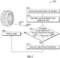
- FIG. 8 shows a flowchart illustrating a method 800 for determining a yaw rate and lateral velocity based on current lateral forces on the tire using a Levenberg-Marquardt method.
- the algorithm computes a vector:
- X ⁇ v des ⁇ des ⁇ indicating a desired lateral velocity and a desired yaw rate that can be obtained given current forces.
- the vector X is used to determine a yaw moment.
- the determined yaw moment is compared to the maximum yaw moment to determine the desired yaw rate and desired lateral velocity, as discussed below.
- a residual sum of squares is determined from the difference between the maximum applicable yaw moment and the determined yaw moment.
- a comparison is made between the residual sum of squares and a sum of squares from a previous iteration (referred to herein as “old sum of squares”). If the residual sum of squares is less than the old sum of squares, then the method proceeds to box 808 .
- a damping factor for the Levenberg-Marquardt algorithm is increased. If instead at box 806 , the residual sum of squares is greater than the old sum of squares, then the method proceeds to box 810 . In box 810 , the damping factor for the Levenberg-Marquardt algorithm is reduced. Finally, if instead at box 806 , the residual sum of squares is approximately equal to the old sum of squares, then the method proceeds to box 812 . In box 812 , a check is made to determine whether the damping factor is equal to zero. If the damping factor is equal to zero, then the process ends at box 814 .
- the damping factor is set to zero.
- the method proceeds to box 818 where the Jacobian matrix is determined.
- the method returns to box 804 . This method continues until a maximum yaw moment is determined to equal zero. The resulting yaw rate and lateral forces are then provided to the DCI in order to operate the vehicle.
Landscapes
- Engineering & Computer Science (AREA)
- Automation & Control Theory (AREA)
- Transportation (AREA)
- Mechanical Engineering (AREA)
- Human Computer Interaction (AREA)
- Steering Control In Accordance With Driving Conditions (AREA)
- Control Of Driving Devices And Active Controlling Of Vehicle (AREA)
Abstract
Description
u FL =u CG −ψT F Eq. (1)
u FR =u CG +ψT F Eq. (2)
u RL =u CG −ψT R Eq. (3)
u RR =u CG −ψT R Eq. (4)
where FL refers to front left, FR refers to front right, RL refers to rear left and RR refers to rear right. TF is the front track width or perpendicular distance from the front tires to the longitudinal axis and TR is the rear track width or perpendicular distance from the rear tires to the longitudinal axis, as shown in
u FL
u FR
u RL
u RR
where ωi is the rotational velocity of the ith tire and Reff is the effective radius of the tire. These relative longitudinal velocities can be used to determine longitudinal slip ratios.
v FL=δFL ×u FL−(v CG +ψL F) Eq. (9)
v FR=δFR ×u FR−(v CG +ψL F) Eq. (10)
v RL=δRL ×u RL−(v CG +ψL R) Eq. (11)
v RR=δRR ×u RR−(v CG +ψL R) Eq. (12)
where vi is the lateral velocity of the ith tire and δi is the steering angle of the ith tire. The relative lateral velocities are determined as shown below in Eqs. (13)-(16), and can be used to determine lateral slip ratios.
v FL
v FR
v RL
v RR
F Y =f(u rel ,v rel) Eq. (19)
F X =g(u rel ,v rel) Eq. (20)
where f and g are standard tire models. Alternatively, the actual forces FY and FX can be determined using empirical tire lookup tables.
M z max =M z,Fy max +M z,Fx max Eq. (21)
where Mz max is the maximum yaw moment of a tire, Mz,Fy max is the maximum yaw moment due to the lateral force on the tire and Mz,Fx max is the maximum yaw moment due to the longitudinal force on the tire. The maximum yaw moment due to lateral forces can be written as:
M z,Fy max =L f ×F y,front max −L r ×F y,rear max Eq. (22)
When Mz max>0, then the rear tires are the first to saturate. When Mz max<0, the front tires are the first to saturate. When Mz max=0, then both the front tires and rear tires saturate simultaneously or together. Thus, the condition for both axles to reach the maximum grip of their tires at the same time is given by Eq. (23):
M z,Fy max =−M z,Fx max Eq. (23)
indicating a desired lateral velocity and a desired yaw rate that can be obtained given current forces.
Claims (9)
Priority Applications (2)
| Application Number | Priority Date | Filing Date | Title |
|---|---|---|---|
| US16/392,005 US11529948B2 (en) | 2019-04-23 | 2019-04-23 | Architecture and methodology of limit handling intended driver command interpreter to achieve maximum lateral grip |
| DE102020107348.8A DE102020107348A1 (en) | 2019-04-23 | 2020-03-17 | ARCHITECTURE AND METHODOLOGY OF A LIMIT HANDLING DRIVER COMMAND INTERPRETER TO ACHIEVE MAXIMUM LATERAL GRIP |
Applications Claiming Priority (1)
| Application Number | Priority Date | Filing Date | Title |
|---|---|---|---|
| US16/392,005 US11529948B2 (en) | 2019-04-23 | 2019-04-23 | Architecture and methodology of limit handling intended driver command interpreter to achieve maximum lateral grip |
Publications (2)
| Publication Number | Publication Date |
|---|---|
| US20200339104A1 US20200339104A1 (en) | 2020-10-29 |
| US11529948B2 true US11529948B2 (en) | 2022-12-20 |
Family
ID=72839774
Family Applications (1)
| Application Number | Title | Priority Date | Filing Date |
|---|---|---|---|
| US16/392,005 Active 2040-01-25 US11529948B2 (en) | 2019-04-23 | 2019-04-23 | Architecture and methodology of limit handling intended driver command interpreter to achieve maximum lateral grip |
Country Status (2)
| Country | Link |
|---|---|
| US (1) | US11529948B2 (en) |
| DE (1) | DE102020107348A1 (en) |
Cited By (1)
| Publication number | Priority date | Publication date | Assignee | Title |
|---|---|---|---|---|
| US20230136325A1 (en) * | 2021-10-30 | 2023-05-04 | Zoox, Inc. | Estimating vehicle velocity |
Families Citing this family (2)
| Publication number | Priority date | Publication date | Assignee | Title |
|---|---|---|---|---|
| DE102021103357A1 (en) | 2021-02-12 | 2022-08-18 | Bayerische Motoren Werke Aktiengesellschaft | Adjusting a gain factor of an acceleration controller for a motor vehicle |
| US12179781B2 (en) * | 2022-12-01 | 2024-12-31 | GM Global Technology Operations LLC | Driver command interpreter system determining achievable target vehicle state during steady-state and transient driving conditions |
Citations (22)
| Publication number | Priority date | Publication date | Assignee | Title |
|---|---|---|---|---|
| US5941919A (en) * | 1996-10-16 | 1999-08-24 | General Motors Corporation | Chassis control system |
| US20020109402A1 (en) * | 2000-11-20 | 2002-08-15 | Toyota Jidosha Kabushiki Kaisha | Vehicle motion control device and method |
| US20020143451A1 (en) * | 2001-01-25 | 2002-10-03 | Delphi Automotive Systems | Integrated control of active tire steer and brakes |
| US20030074122A1 (en) * | 2001-10-12 | 2003-04-17 | Delphi Technologies Inc. | Dynamic side to side brake proportioning |
| US20030125847A1 (en) * | 2001-12-28 | 2003-07-03 | Tinskey Michael R. | Vehicle stability control |
| US6658342B1 (en) * | 2002-06-05 | 2003-12-02 | Delphi Technologies, Inc. | Vehicle stability control |
| US20050033486A1 (en) * | 2001-11-05 | 2005-02-10 | Paul Schmitt | System and method for controlling a safety system of a vehicle in response to conditions sensed by tire sensors related applications |
| JP2006315661A (en) * | 2005-04-15 | 2006-11-24 | Nissan Motor Co Ltd | Driving force distribution device for four-wheel independent drive vehicle |
| US20080208406A1 (en) | 2007-02-28 | 2008-08-28 | Gm Global Technology Operations, Inc. | Nonlinear vehicle yaw/roll/sideslip command interpreter |
| US20080221766A1 (en) * | 2005-02-02 | 2008-09-11 | Yoshinori Maeda | Braking/Driving Force Controller of Vehicle |
| US7451032B2 (en) * | 2004-06-02 | 2008-11-11 | Ford Global Technologies, Llc | System and method for determining desired yaw rate and lateral velocity for use in a vehicle dynamic control system |
| US20090118905A1 (en) * | 2005-12-27 | 2009-05-07 | Honda Motor Co., Ltd. | Vehicle control device |
| US20100174463A1 (en) * | 2005-06-01 | 2010-07-08 | Toyota Jidosha Kabushiki Kaisha | Vehicle braking/driving force control apparatus |
| JP2010151205A (en) * | 2008-12-25 | 2010-07-08 | Nissan Motor Co Ltd | Driving force distribution control device for vehicle |
| US8073607B2 (en) | 2008-01-28 | 2011-12-06 | GM Global Technology Operations LLC | Method for populating motor vehicle yaw gain tables for use in an electronic stability control system |
| US20120055744A1 (en) * | 2010-09-07 | 2012-03-08 | Gm Global Technology Operations, Inc. | Hybrid brake control |
| US20130144476A1 (en) * | 2010-06-03 | 2013-06-06 | Mira Ltd. | Yaw Motion Control of a Vehicle |
| US8565993B2 (en) * | 2005-10-11 | 2013-10-22 | Volvo Car Corporation | Enhanced yaw stability control to mitigate a vehicle's abnormal yaw motion due to a disturbance force applied to vehicle body |
| US20140145498A1 (en) * | 2010-09-28 | 2014-05-29 | Hitachi Automotive Systems, Ltd. | Motion control system of vehicle |
| US20170057493A1 (en) * | 2015-08-27 | 2017-03-02 | Fuji Jukogyo Kabushiki Kaisha | Vehicle control apparatus and method for controlling vehicle |
| US20190256094A1 (en) | 2018-02-22 | 2019-08-22 | GM Global Technology Operations LLC | Architecture and methodology for target states determination of performance vehicle motion control |
| US20190276009A1 (en) * | 2018-03-07 | 2019-09-12 | Subaru Corporation | Control apparatus for vehicle and control method for vehicle |
-
2019
- 2019-04-23 US US16/392,005 patent/US11529948B2/en active Active
-
2020
- 2020-03-17 DE DE102020107348.8A patent/DE102020107348A1/en active Pending
Patent Citations (22)
| Publication number | Priority date | Publication date | Assignee | Title |
|---|---|---|---|---|
| US5941919A (en) * | 1996-10-16 | 1999-08-24 | General Motors Corporation | Chassis control system |
| US20020109402A1 (en) * | 2000-11-20 | 2002-08-15 | Toyota Jidosha Kabushiki Kaisha | Vehicle motion control device and method |
| US20020143451A1 (en) * | 2001-01-25 | 2002-10-03 | Delphi Automotive Systems | Integrated control of active tire steer and brakes |
| US20030074122A1 (en) * | 2001-10-12 | 2003-04-17 | Delphi Technologies Inc. | Dynamic side to side brake proportioning |
| US20050033486A1 (en) * | 2001-11-05 | 2005-02-10 | Paul Schmitt | System and method for controlling a safety system of a vehicle in response to conditions sensed by tire sensors related applications |
| US20030125847A1 (en) * | 2001-12-28 | 2003-07-03 | Tinskey Michael R. | Vehicle stability control |
| US6658342B1 (en) * | 2002-06-05 | 2003-12-02 | Delphi Technologies, Inc. | Vehicle stability control |
| US7451032B2 (en) * | 2004-06-02 | 2008-11-11 | Ford Global Technologies, Llc | System and method for determining desired yaw rate and lateral velocity for use in a vehicle dynamic control system |
| US20080221766A1 (en) * | 2005-02-02 | 2008-09-11 | Yoshinori Maeda | Braking/Driving Force Controller of Vehicle |
| JP2006315661A (en) * | 2005-04-15 | 2006-11-24 | Nissan Motor Co Ltd | Driving force distribution device for four-wheel independent drive vehicle |
| US20100174463A1 (en) * | 2005-06-01 | 2010-07-08 | Toyota Jidosha Kabushiki Kaisha | Vehicle braking/driving force control apparatus |
| US8565993B2 (en) * | 2005-10-11 | 2013-10-22 | Volvo Car Corporation | Enhanced yaw stability control to mitigate a vehicle's abnormal yaw motion due to a disturbance force applied to vehicle body |
| US20090118905A1 (en) * | 2005-12-27 | 2009-05-07 | Honda Motor Co., Ltd. | Vehicle control device |
| US20080208406A1 (en) | 2007-02-28 | 2008-08-28 | Gm Global Technology Operations, Inc. | Nonlinear vehicle yaw/roll/sideslip command interpreter |
| US8073607B2 (en) | 2008-01-28 | 2011-12-06 | GM Global Technology Operations LLC | Method for populating motor vehicle yaw gain tables for use in an electronic stability control system |
| JP2010151205A (en) * | 2008-12-25 | 2010-07-08 | Nissan Motor Co Ltd | Driving force distribution control device for vehicle |
| US20130144476A1 (en) * | 2010-06-03 | 2013-06-06 | Mira Ltd. | Yaw Motion Control of a Vehicle |
| US20120055744A1 (en) * | 2010-09-07 | 2012-03-08 | Gm Global Technology Operations, Inc. | Hybrid brake control |
| US20140145498A1 (en) * | 2010-09-28 | 2014-05-29 | Hitachi Automotive Systems, Ltd. | Motion control system of vehicle |
| US20170057493A1 (en) * | 2015-08-27 | 2017-03-02 | Fuji Jukogyo Kabushiki Kaisha | Vehicle control apparatus and method for controlling vehicle |
| US20190256094A1 (en) | 2018-02-22 | 2019-08-22 | GM Global Technology Operations LLC | Architecture and methodology for target states determination of performance vehicle motion control |
| US20190276009A1 (en) * | 2018-03-07 | 2019-09-12 | Subaru Corporation | Control apparatus for vehicle and control method for vehicle |
Non-Patent Citations (2)
| Title |
|---|
| Shimodaira et al. Machine Translation of Japanese Patent Application JP 2010151205 A, 2010. (Year: 2010). * |
| Yamaguchi et al. Machine Translation of Japanese Patent Application JP 2006315661A, 2006 (Year: 2006). * |
Cited By (2)
| Publication number | Priority date | Publication date | Assignee | Title |
|---|---|---|---|---|
| US20230136325A1 (en) * | 2021-10-30 | 2023-05-04 | Zoox, Inc. | Estimating vehicle velocity |
| US11872994B2 (en) * | 2021-10-30 | 2024-01-16 | Zoox, Inc. | Estimating vehicle velocity |
Also Published As
| Publication number | Publication date |
|---|---|
| DE102020107348A1 (en) | 2020-10-29 |
| US20200339104A1 (en) | 2020-10-29 |
Similar Documents
| Publication | Publication Date | Title |
|---|---|---|
| CN110481555B (en) | Vehicle path planning method and ride comfort processor | |
| US8301343B2 (en) | Vehicle behavior control device | |
| US20190256094A1 (en) | Architecture and methodology for target states determination of performance vehicle motion control | |
| US9145165B2 (en) | Drive controlling apparatus for a vehicle | |
| US20170313304A1 (en) | Travel control device for vehicle | |
| US11731654B2 (en) | Vehicle control systems and methods | |
| US11396287B2 (en) | Architecture and methodology for real-time target wheel slip identification to optimally manage wheel stability and vehicle lateral grip | |
| US11097743B2 (en) | Method and system for controlling a vehicle by determining a location of an optimum perceived yaw center | |
| US20170361834A1 (en) | System for mitigating vehicle sway | |
| US11780449B2 (en) | System and method to estimate maximum lateral acceleration and yaw rate in limit handling maneuvers in low-friction surfaces | |
| CN111806420A (en) | A method of controlling the torque distribution of the axle | |
| US11529948B2 (en) | Architecture and methodology of limit handling intended driver command interpreter to achieve maximum lateral grip | |
| CN116135558A (en) | Method for controlling axle load distribution of a vehicle | |
| JP2022533507A (en) | Method for estimating vehicle motion state during vehicle operation | |
| US12589733B2 (en) | Determination apparatus of center of gravity position, and determination method thereof | |
| US12427861B2 (en) | Detection method of loading anomaly on vehicle, and detection apparatus thereof | |
| US11175667B2 (en) | System and method for vehicle integrated stability control using perceived yaw center | |
| US12221182B2 (en) | Online estimation methods and systems for electric power steering parameters for use in automated driving controls | |
| US11794777B1 (en) | Systems and methods for estimating heading and yaw rate for automated driving | |
| US12304482B2 (en) | Systems and methods for estimating vehicle parameters | |
| US12485751B2 (en) | Methods and systems for using road preview to control vehicle velocity during cornering | |
| US20250242817A1 (en) | Control barrier functions for safety-critical control of automotive stability | |
| CN117719490A (en) | Vehicle driving stability adaptive control system and control method |
Legal Events
| Date | Code | Title | Description |
|---|---|---|---|
| AS | Assignment |
Owner name: GM GLOBAL TECHNOLOGY OPERATIONS LLC, MICHIGAN Free format text: ASSIGNMENT OF ASSIGNORS INTEREST;ASSIGNORS:NAHIDI, SEYEDEH ASAL;MAHABADI, SEYEDALIREZA KASAIEZADEH;HOLBROOK, JAMES H.;AND OTHERS;SIGNING DATES FROM 20190411 TO 20190415;REEL/FRAME:048973/0373 |
|
| FEPP | Fee payment procedure |
Free format text: ENTITY STATUS SET TO UNDISCOUNTED (ORIGINAL EVENT CODE: BIG.); ENTITY STATUS OF PATENT OWNER: LARGE ENTITY |
|
| STPP | Information on status: patent application and granting procedure in general |
Free format text: NON FINAL ACTION MAILED |
|
| STPP | Information on status: patent application and granting procedure in general |
Free format text: RESPONSE TO NON-FINAL OFFICE ACTION ENTERED AND FORWARDED TO EXAMINER |
|
| STPP | Information on status: patent application and granting procedure in general |
Free format text: FINAL REJECTION MAILED |
|
| STPP | Information on status: patent application and granting procedure in general |
Free format text: RESPONSE AFTER FINAL ACTION FORWARDED TO EXAMINER |
|
| STPP | Information on status: patent application and granting procedure in general |
Free format text: ADVISORY ACTION MAILED |
|
| STPP | Information on status: patent application and granting procedure in general |
Free format text: DOCKETED NEW CASE - READY FOR EXAMINATION |
|
| STPP | Information on status: patent application and granting procedure in general |
Free format text: NON FINAL ACTION MAILED |
|
| STPP | Information on status: patent application and granting procedure in general |
Free format text: RESPONSE TO NON-FINAL OFFICE ACTION ENTERED AND FORWARDED TO EXAMINER |
|
| STPP | Information on status: patent application and granting procedure in general |
Free format text: NOTICE OF ALLOWANCE MAILED -- APPLICATION RECEIVED IN OFFICE OF PUBLICATIONS |
|
| STPP | Information on status: patent application and granting procedure in general |
Free format text: PUBLICATIONS -- ISSUE FEE PAYMENT VERIFIED |
|
| STCF | Information on status: patent grant |
Free format text: PATENTED CASE |