US11527638B2 - Semiconductor device and method for fabricating the same - Google Patents
Semiconductor device and method for fabricating the same Download PDFInfo
- Publication number
- US11527638B2 US11527638B2 US17/161,696 US202117161696A US11527638B2 US 11527638 B2 US11527638 B2 US 11527638B2 US 202117161696 A US202117161696 A US 202117161696A US 11527638 B2 US11527638 B2 US 11527638B2
- Authority
- US
- United States
- Prior art keywords
- gate
- layer
- trench
- fin
- forming
- Prior art date
- Legal status (The legal status is an assumption and is not a legal conclusion. Google has not performed a legal analysis and makes no representation as to the accuracy of the status listed.)
- Active, expires
Links
- 238000000034 method Methods 0.000 title claims abstract description 59
- 239000004065 semiconductor Substances 0.000 title claims abstract description 38
- 239000000758 substrate Substances 0.000 claims abstract description 19
- 239000010410 layer Substances 0.000 claims description 119
- 238000002955 isolation Methods 0.000 claims description 54
- 229910052751 metal Inorganic materials 0.000 claims description 26
- 239000002184 metal Substances 0.000 claims description 26
- 125000006850 spacer group Chemical group 0.000 claims description 25
- 238000009792 diffusion process Methods 0.000 claims description 4
- 239000011229 interlayer Substances 0.000 claims description 2
- 239000000463 material Substances 0.000 description 11
- VYPSYNLAJGMNEJ-UHFFFAOYSA-N Silicium dioxide Chemical compound O=[Si]=O VYPSYNLAJGMNEJ-UHFFFAOYSA-N 0.000 description 10
- 238000005530 etching Methods 0.000 description 8
- 229910052581 Si3N4 Inorganic materials 0.000 description 7
- HQVNEWCFYHHQES-UHFFFAOYSA-N silicon nitride Chemical compound N12[Si]34N5[Si]62N3[Si]51N64 HQVNEWCFYHHQES-UHFFFAOYSA-N 0.000 description 7
- 229910052814 silicon oxide Inorganic materials 0.000 description 6
- XUIMIQQOPSSXEZ-UHFFFAOYSA-N Silicon Chemical compound [Si] XUIMIQQOPSSXEZ-UHFFFAOYSA-N 0.000 description 5
- 230000004888 barrier function Effects 0.000 description 5
- 238000004519 manufacturing process Methods 0.000 description 5
- 229910052710 silicon Inorganic materials 0.000 description 5
- 239000010703 silicon Substances 0.000 description 5
- 229910000951 Aluminide Inorganic materials 0.000 description 4
- OQPDWFJSZHWILH-UHFFFAOYSA-N [Al].[Al].[Al].[Ti] Chemical compound [Al].[Al].[Al].[Ti] OQPDWFJSZHWILH-UHFFFAOYSA-N 0.000 description 4
- 239000003989 dielectric material Substances 0.000 description 4
- MZLGASXMSKOWSE-UHFFFAOYSA-N tantalum nitride Chemical compound [Ta]#N MZLGASXMSKOWSE-UHFFFAOYSA-N 0.000 description 4
- WGTYBPLFGIVFAS-UHFFFAOYSA-M tetramethylammonium hydroxide Chemical compound [OH-].C[N+](C)(C)C WGTYBPLFGIVFAS-UHFFFAOYSA-M 0.000 description 4
- 229910021324 titanium aluminide Inorganic materials 0.000 description 4
- NRTOMJZYCJJWKI-UHFFFAOYSA-N Titanium nitride Chemical compound [Ti]#N NRTOMJZYCJJWKI-UHFFFAOYSA-N 0.000 description 3
- 239000010949 copper Substances 0.000 description 3
- 239000010936 titanium Substances 0.000 description 3
- VHUUQVKOLVNVRT-UHFFFAOYSA-N Ammonium hydroxide Chemical compound [NH4+].[OH-] VHUUQVKOLVNVRT-UHFFFAOYSA-N 0.000 description 2
- UQZIWOQVLUASCR-UHFFFAOYSA-N alumane;titanium Chemical compound [AlH3].[Ti] UQZIWOQVLUASCR-UHFFFAOYSA-N 0.000 description 2
- 229910052782 aluminium Inorganic materials 0.000 description 2
- 239000006117 anti-reflective coating Substances 0.000 description 2
- 229910052454 barium strontium titanate Inorganic materials 0.000 description 2
- 230000015572 biosynthetic process Effects 0.000 description 2
- 229910052681 coesite Inorganic materials 0.000 description 2
- 239000002131 composite material Substances 0.000 description 2
- 229910052802 copper Inorganic materials 0.000 description 2
- 229910052906 cristobalite Inorganic materials 0.000 description 2
- 230000000694 effects Effects 0.000 description 2
- 238000005516 engineering process Methods 0.000 description 2
- 229910052451 lead zirconate titanate Inorganic materials 0.000 description 2
- NFFIWVVINABMKP-UHFFFAOYSA-N methylidynetantalum Chemical compound [Ta]#C NFFIWVVINABMKP-UHFFFAOYSA-N 0.000 description 2
- TWNQGVIAIRXVLR-UHFFFAOYSA-N oxo(oxoalumanyloxy)alumane Chemical compound O=[Al]O[Al]=O TWNQGVIAIRXVLR-UHFFFAOYSA-N 0.000 description 2
- SIWVEOZUMHYXCS-UHFFFAOYSA-N oxo(oxoyttriooxy)yttrium Chemical compound O=[Y]O[Y]=O SIWVEOZUMHYXCS-UHFFFAOYSA-N 0.000 description 2
- RVTZCBVAJQQJTK-UHFFFAOYSA-N oxygen(2-);zirconium(4+) Chemical compound [O-2].[O-2].[Zr+4] RVTZCBVAJQQJTK-UHFFFAOYSA-N 0.000 description 2
- 238000005498 polishing Methods 0.000 description 2
- 239000000377 silicon dioxide Substances 0.000 description 2
- 229910052682 stishovite Inorganic materials 0.000 description 2
- 239000000126 substance Substances 0.000 description 2
- 229910003468 tantalcarbide Inorganic materials 0.000 description 2
- 229910052715 tantalum Inorganic materials 0.000 description 2
- GUVRBAGPIYLISA-UHFFFAOYSA-N tantalum atom Chemical compound [Ta] GUVRBAGPIYLISA-UHFFFAOYSA-N 0.000 description 2
- 229910052719 titanium Inorganic materials 0.000 description 2
- 229910052905 tridymite Inorganic materials 0.000 description 2
- 229910052721 tungsten Inorganic materials 0.000 description 2
- 229910001928 zirconium oxide Inorganic materials 0.000 description 2
- 229910015846 BaxSr1-xTiO3 Inorganic materials 0.000 description 1
- RYGMFSIKBFXOCR-UHFFFAOYSA-N Copper Chemical compound [Cu] RYGMFSIKBFXOCR-UHFFFAOYSA-N 0.000 description 1
- 229910020696 PbZrxTi1−xO3 Inorganic materials 0.000 description 1
- 229910000577 Silicon-germanium Inorganic materials 0.000 description 1
- RTAQQCXQSZGOHL-UHFFFAOYSA-N Titanium Chemical compound [Ti] RTAQQCXQSZGOHL-UHFFFAOYSA-N 0.000 description 1
- QCWXUUIWCKQGHC-UHFFFAOYSA-N Zirconium Chemical compound [Zr] QCWXUUIWCKQGHC-UHFFFAOYSA-N 0.000 description 1
- LEVVHYCKPQWKOP-UHFFFAOYSA-N [Si].[Ge] Chemical compound [Si].[Ge] LEVVHYCKPQWKOP-UHFFFAOYSA-N 0.000 description 1
- CEPICIBPGDWCRU-UHFFFAOYSA-N [Si].[Hf] Chemical compound [Si].[Hf] CEPICIBPGDWCRU-UHFFFAOYSA-N 0.000 description 1
- ILCYGSITMBHYNK-UHFFFAOYSA-N [Si]=O.[Hf] Chemical compound [Si]=O.[Hf] ILCYGSITMBHYNK-UHFFFAOYSA-N 0.000 description 1
- VNSWULZVUKFJHK-UHFFFAOYSA-N [Sr].[Bi] Chemical compound [Sr].[Bi] VNSWULZVUKFJHK-UHFFFAOYSA-N 0.000 description 1
- 230000004075 alteration Effects 0.000 description 1
- XAGFODPZIPBFFR-UHFFFAOYSA-N aluminium Chemical compound [Al] XAGFODPZIPBFFR-UHFFFAOYSA-N 0.000 description 1
- 239000000908 ammonium hydroxide Substances 0.000 description 1
- 229910021417 amorphous silicon Inorganic materials 0.000 description 1
- 238000013459 approach Methods 0.000 description 1
- 238000004364 calculation method Methods 0.000 description 1
- 238000005229 chemical vapour deposition Methods 0.000 description 1
- JPNWDVUTVSTKMV-UHFFFAOYSA-N cobalt tungsten Chemical compound [Co].[W] JPNWDVUTVSTKMV-UHFFFAOYSA-N 0.000 description 1
- 238000000151 deposition Methods 0.000 description 1
- 238000005137 deposition process Methods 0.000 description 1
- 239000002019 doping agent Substances 0.000 description 1
- 238000001312 dry etching Methods 0.000 description 1
- 230000005669 field effect Effects 0.000 description 1
- 230000009969 flowable effect Effects 0.000 description 1
- 229910052735 hafnium Inorganic materials 0.000 description 1
- VBJZVLUMGGDVMO-UHFFFAOYSA-N hafnium atom Chemical compound [Hf] VBJZVLUMGGDVMO-UHFFFAOYSA-N 0.000 description 1
- KQHQLIAOAVMAOW-UHFFFAOYSA-N hafnium(4+) oxygen(2-) zirconium(4+) Chemical compound [O--].[O--].[O--].[O--].[Zr+4].[Hf+4] KQHQLIAOAVMAOW-UHFFFAOYSA-N 0.000 description 1
- CJNBYAVZURUTKZ-UHFFFAOYSA-N hafnium(iv) oxide Chemical compound O=[Hf]=O CJNBYAVZURUTKZ-UHFFFAOYSA-N 0.000 description 1
- 239000011810 insulating material Substances 0.000 description 1
- 239000012212 insulator Substances 0.000 description 1
- 230000010354 integration Effects 0.000 description 1
- MRELNEQAGSRDBK-UHFFFAOYSA-N lanthanum(3+);oxygen(2-) Chemical compound [O-2].[O-2].[O-2].[La+3].[La+3] MRELNEQAGSRDBK-UHFFFAOYSA-N 0.000 description 1
- HFGPZNIAWCZYJU-UHFFFAOYSA-N lead zirconate titanate Chemical compound [O-2].[O-2].[O-2].[O-2].[O-2].[Ti+4].[Zr+4].[Pb+2] HFGPZNIAWCZYJU-UHFFFAOYSA-N 0.000 description 1
- 229910044991 metal oxide Inorganic materials 0.000 description 1
- 150000004706 metal oxides Chemical class 0.000 description 1
- 150000002739 metals Chemical class 0.000 description 1
- 238000012986 modification Methods 0.000 description 1
- 230000004048 modification Effects 0.000 description 1
- BPUBBGLMJRNUCC-UHFFFAOYSA-N oxygen(2-);tantalum(5+) Chemical compound [O-2].[O-2].[O-2].[O-2].[O-2].[Ta+5].[Ta+5] BPUBBGLMJRNUCC-UHFFFAOYSA-N 0.000 description 1
- 229910021420 polycrystalline silicon Inorganic materials 0.000 description 1
- 229920005591 polysilicon Polymers 0.000 description 1
- 229910021332 silicide Inorganic materials 0.000 description 1
- VEALVRVVWBQVSL-UHFFFAOYSA-N strontium titanate Chemical compound [Sr+2].[O-][Ti]([O-])=O VEALVRVVWBQVSL-UHFFFAOYSA-N 0.000 description 1
- WFKWXMTUELFFGS-UHFFFAOYSA-N tungsten Chemical compound [W] WFKWXMTUELFFGS-UHFFFAOYSA-N 0.000 description 1
- 239000010937 tungsten Substances 0.000 description 1
- 238000001039 wet etching Methods 0.000 description 1
- 229910052726 zirconium Inorganic materials 0.000 description 1
- GFQYVLUOOAAOGM-UHFFFAOYSA-N zirconium(iv) silicate Chemical compound [Zr+4].[O-][Si]([O-])([O-])[O-] GFQYVLUOOAAOGM-UHFFFAOYSA-N 0.000 description 1
Images


Classifications
-
- H—ELECTRICITY
- H01—ELECTRIC ELEMENTS
- H01L—SEMICONDUCTOR DEVICES NOT COVERED BY CLASS H10
- H01L21/00—Processes or apparatus adapted for the manufacture or treatment of semiconductor or solid state devices or of parts thereof
- H01L21/70—Manufacture or treatment of devices consisting of a plurality of solid state components formed in or on a common substrate or of parts thereof; Manufacture of integrated circuit devices or of parts thereof
- H01L21/77—Manufacture or treatment of devices consisting of a plurality of solid state components or integrated circuits formed in, or on, a common substrate
- H01L21/78—Manufacture or treatment of devices consisting of a plurality of solid state components or integrated circuits formed in, or on, a common substrate with subsequent division of the substrate into plural individual devices
- H01L21/82—Manufacture or treatment of devices consisting of a plurality of solid state components or integrated circuits formed in, or on, a common substrate with subsequent division of the substrate into plural individual devices to produce devices, e.g. integrated circuits, each consisting of a plurality of components
- H01L21/822—Manufacture or treatment of devices consisting of a plurality of solid state components or integrated circuits formed in, or on, a common substrate with subsequent division of the substrate into plural individual devices to produce devices, e.g. integrated circuits, each consisting of a plurality of components the substrate being a semiconductor, using silicon technology
- H01L21/8232—Field-effect technology
- H01L21/8234—MIS technology, i.e. integration processes of field effect transistors of the conductor-insulator-semiconductor type
- H01L21/823431—MIS technology, i.e. integration processes of field effect transistors of the conductor-insulator-semiconductor type with a particular manufacturing method of transistors with a horizontal current flow in a vertical sidewall of a semiconductor body, e.g. FinFET, MuGFET
-
- H—ELECTRICITY
- H01—ELECTRIC ELEMENTS
- H01L—SEMICONDUCTOR DEVICES NOT COVERED BY CLASS H10
- H01L29/00—Semiconductor devices adapted for rectifying, amplifying, oscillating or switching, or capacitors or resistors with at least one potential-jump barrier or surface barrier, e.g. PN junction depletion layer or carrier concentration layer; Details of semiconductor bodies or of electrodes thereof ; Multistep manufacturing processes therefor
- H01L29/66—Types of semiconductor device ; Multistep manufacturing processes therefor
- H01L29/66007—Multistep manufacturing processes
- H01L29/66075—Multistep manufacturing processes of devices having semiconductor bodies comprising group 14 or group 13/15 materials
- H01L29/66227—Multistep manufacturing processes of devices having semiconductor bodies comprising group 14 or group 13/15 materials the devices being controllable only by the electric current supplied or the electric potential applied, to an electrode which does not carry the current to be rectified, amplified or switched, e.g. three-terminal devices
- H01L29/66409—Unipolar field-effect transistors
- H01L29/66477—Unipolar field-effect transistors with an insulated gate, i.e. MISFET
- H01L29/66787—Unipolar field-effect transistors with an insulated gate, i.e. MISFET with a gate at the side of the channel
- H01L29/66795—Unipolar field-effect transistors with an insulated gate, i.e. MISFET with a gate at the side of the channel with a horizontal current flow in a vertical sidewall of a semiconductor body, e.g. FinFET, MuGFET
-
- H—ELECTRICITY
- H01—ELECTRIC ELEMENTS
- H01L—SEMICONDUCTOR DEVICES NOT COVERED BY CLASS H10
- H01L21/00—Processes or apparatus adapted for the manufacture or treatment of semiconductor or solid state devices or of parts thereof
- H01L21/70—Manufacture or treatment of devices consisting of a plurality of solid state components formed in or on a common substrate or of parts thereof; Manufacture of integrated circuit devices or of parts thereof
- H01L21/71—Manufacture of specific parts of devices defined in group H01L21/70
- H01L21/76—Making of isolation regions between components
- H01L21/762—Dielectric regions, e.g. EPIC dielectric isolation, LOCOS; Trench refilling techniques, SOI technology, use of channel stoppers
- H01L21/76224—Dielectric regions, e.g. EPIC dielectric isolation, LOCOS; Trench refilling techniques, SOI technology, use of channel stoppers using trench refilling with dielectric materials
- H01L21/76232—Dielectric regions, e.g. EPIC dielectric isolation, LOCOS; Trench refilling techniques, SOI technology, use of channel stoppers using trench refilling with dielectric materials of trenches having a shape other than rectangular or V-shape, e.g. rounded corners, oblique or rounded trench walls
-
- H—ELECTRICITY
- H01—ELECTRIC ELEMENTS
- H01L—SEMICONDUCTOR DEVICES NOT COVERED BY CLASS H10
- H01L21/00—Processes or apparatus adapted for the manufacture or treatment of semiconductor or solid state devices or of parts thereof
- H01L21/70—Manufacture or treatment of devices consisting of a plurality of solid state components formed in or on a common substrate or of parts thereof; Manufacture of integrated circuit devices or of parts thereof
- H01L21/77—Manufacture or treatment of devices consisting of a plurality of solid state components or integrated circuits formed in, or on, a common substrate
- H01L21/78—Manufacture or treatment of devices consisting of a plurality of solid state components or integrated circuits formed in, or on, a common substrate with subsequent division of the substrate into plural individual devices
- H01L21/82—Manufacture or treatment of devices consisting of a plurality of solid state components or integrated circuits formed in, or on, a common substrate with subsequent division of the substrate into plural individual devices to produce devices, e.g. integrated circuits, each consisting of a plurality of components
- H01L21/822—Manufacture or treatment of devices consisting of a plurality of solid state components or integrated circuits formed in, or on, a common substrate with subsequent division of the substrate into plural individual devices to produce devices, e.g. integrated circuits, each consisting of a plurality of components the substrate being a semiconductor, using silicon technology
- H01L21/8232—Field-effect technology
- H01L21/8234—MIS technology, i.e. integration processes of field effect transistors of the conductor-insulator-semiconductor type
- H01L21/823468—MIS technology, i.e. integration processes of field effect transistors of the conductor-insulator-semiconductor type with a particular manufacturing method of the gate sidewall spacers, e.g. double spacers, particular spacer material or shape
-
- H—ELECTRICITY
- H01—ELECTRIC ELEMENTS
- H01L—SEMICONDUCTOR DEVICES NOT COVERED BY CLASS H10
- H01L21/00—Processes or apparatus adapted for the manufacture or treatment of semiconductor or solid state devices or of parts thereof
- H01L21/70—Manufacture or treatment of devices consisting of a plurality of solid state components formed in or on a common substrate or of parts thereof; Manufacture of integrated circuit devices or of parts thereof
- H01L21/77—Manufacture or treatment of devices consisting of a plurality of solid state components or integrated circuits formed in, or on, a common substrate
- H01L21/78—Manufacture or treatment of devices consisting of a plurality of solid state components or integrated circuits formed in, or on, a common substrate with subsequent division of the substrate into plural individual devices
- H01L21/82—Manufacture or treatment of devices consisting of a plurality of solid state components or integrated circuits formed in, or on, a common substrate with subsequent division of the substrate into plural individual devices to produce devices, e.g. integrated circuits, each consisting of a plurality of components
- H01L21/822—Manufacture or treatment of devices consisting of a plurality of solid state components or integrated circuits formed in, or on, a common substrate with subsequent division of the substrate into plural individual devices to produce devices, e.g. integrated circuits, each consisting of a plurality of components the substrate being a semiconductor, using silicon technology
- H01L21/8232—Field-effect technology
- H01L21/8234—MIS technology, i.e. integration processes of field effect transistors of the conductor-insulator-semiconductor type
- H01L21/823481—MIS technology, i.e. integration processes of field effect transistors of the conductor-insulator-semiconductor type isolation region manufacturing related aspects, e.g. to avoid interaction of isolation region with adjacent structure
-
- H—ELECTRICITY
- H01—ELECTRIC ELEMENTS
- H01L—SEMICONDUCTOR DEVICES NOT COVERED BY CLASS H10
- H01L27/00—Devices consisting of a plurality of semiconductor or other solid-state components formed in or on a common substrate
- H01L27/02—Devices consisting of a plurality of semiconductor or other solid-state components formed in or on a common substrate including semiconductor components specially adapted for rectifying, oscillating, amplifying or switching and having at least one potential-jump barrier or surface barrier; including integrated passive circuit elements with at least one potential-jump barrier or surface barrier
- H01L27/04—Devices consisting of a plurality of semiconductor or other solid-state components formed in or on a common substrate including semiconductor components specially adapted for rectifying, oscillating, amplifying or switching and having at least one potential-jump barrier or surface barrier; including integrated passive circuit elements with at least one potential-jump barrier or surface barrier the substrate being a semiconductor body
- H01L27/08—Devices consisting of a plurality of semiconductor or other solid-state components formed in or on a common substrate including semiconductor components specially adapted for rectifying, oscillating, amplifying or switching and having at least one potential-jump barrier or surface barrier; including integrated passive circuit elements with at least one potential-jump barrier or surface barrier the substrate being a semiconductor body including only semiconductor components of a single kind
- H01L27/085—Devices consisting of a plurality of semiconductor or other solid-state components formed in or on a common substrate including semiconductor components specially adapted for rectifying, oscillating, amplifying or switching and having at least one potential-jump barrier or surface barrier; including integrated passive circuit elements with at least one potential-jump barrier or surface barrier the substrate being a semiconductor body including only semiconductor components of a single kind including field-effect components only
- H01L27/088—Devices consisting of a plurality of semiconductor or other solid-state components formed in or on a common substrate including semiconductor components specially adapted for rectifying, oscillating, amplifying or switching and having at least one potential-jump barrier or surface barrier; including integrated passive circuit elements with at least one potential-jump barrier or surface barrier the substrate being a semiconductor body including only semiconductor components of a single kind including field-effect components only the components being field-effect transistors with insulated gate
- H01L27/0886—Devices consisting of a plurality of semiconductor or other solid-state components formed in or on a common substrate including semiconductor components specially adapted for rectifying, oscillating, amplifying or switching and having at least one potential-jump barrier or surface barrier; including integrated passive circuit elements with at least one potential-jump barrier or surface barrier the substrate being a semiconductor body including only semiconductor components of a single kind including field-effect components only the components being field-effect transistors with insulated gate including transistors with a horizontal current flow in a vertical sidewall of a semiconductor body, e.g. FinFET, MuGFET
-
- H—ELECTRICITY
- H01—ELECTRIC ELEMENTS
- H01L—SEMICONDUCTOR DEVICES NOT COVERED BY CLASS H10
- H01L29/00—Semiconductor devices adapted for rectifying, amplifying, oscillating or switching, or capacitors or resistors with at least one potential-jump barrier or surface barrier, e.g. PN junction depletion layer or carrier concentration layer; Details of semiconductor bodies or of electrodes thereof ; Multistep manufacturing processes therefor
- H01L29/66—Types of semiconductor device ; Multistep manufacturing processes therefor
- H01L29/66007—Multistep manufacturing processes
- H01L29/66075—Multistep manufacturing processes of devices having semiconductor bodies comprising group 14 or group 13/15 materials
- H01L29/66227—Multistep manufacturing processes of devices having semiconductor bodies comprising group 14 or group 13/15 materials the devices being controllable only by the electric current supplied or the electric potential applied, to an electrode which does not carry the current to be rectified, amplified or switched, e.g. three-terminal devices
- H01L29/66409—Unipolar field-effect transistors
- H01L29/66477—Unipolar field-effect transistors with an insulated gate, i.e. MISFET
- H01L29/6656—Unipolar field-effect transistors with an insulated gate, i.e. MISFET using multiple spacer layers, e.g. multiple sidewall spacers
-
- H—ELECTRICITY
- H01—ELECTRIC ELEMENTS
- H01L—SEMICONDUCTOR DEVICES NOT COVERED BY CLASS H10
- H01L29/00—Semiconductor devices adapted for rectifying, amplifying, oscillating or switching, or capacitors or resistors with at least one potential-jump barrier or surface barrier, e.g. PN junction depletion layer or carrier concentration layer; Details of semiconductor bodies or of electrodes thereof ; Multistep manufacturing processes therefor
- H01L29/66—Types of semiconductor device ; Multistep manufacturing processes therefor
- H01L29/66007—Multistep manufacturing processes
- H01L29/66075—Multistep manufacturing processes of devices having semiconductor bodies comprising group 14 or group 13/15 materials
- H01L29/66227—Multistep manufacturing processes of devices having semiconductor bodies comprising group 14 or group 13/15 materials the devices being controllable only by the electric current supplied or the electric potential applied, to an electrode which does not carry the current to be rectified, amplified or switched, e.g. three-terminal devices
- H01L29/66409—Unipolar field-effect transistors
- H01L29/66477—Unipolar field-effect transistors with an insulated gate, i.e. MISFET
- H01L29/66568—Lateral single gate silicon transistors
- H01L29/66613—Lateral single gate silicon transistors with a gate recessing step, e.g. using local oxidation
- H01L29/66628—Lateral single gate silicon transistors with a gate recessing step, e.g. using local oxidation recessing the gate by forming single crystalline semiconductor material at the source or drain location
-
- H—ELECTRICITY
- H01—ELECTRIC ELEMENTS
- H01L—SEMICONDUCTOR DEVICES NOT COVERED BY CLASS H10
- H01L29/00—Semiconductor devices adapted for rectifying, amplifying, oscillating or switching, or capacitors or resistors with at least one potential-jump barrier or surface barrier, e.g. PN junction depletion layer or carrier concentration layer; Details of semiconductor bodies or of electrodes thereof ; Multistep manufacturing processes therefor
- H01L29/66—Types of semiconductor device ; Multistep manufacturing processes therefor
- H01L29/66007—Multistep manufacturing processes
- H01L29/66075—Multistep manufacturing processes of devices having semiconductor bodies comprising group 14 or group 13/15 materials
- H01L29/66227—Multistep manufacturing processes of devices having semiconductor bodies comprising group 14 or group 13/15 materials the devices being controllable only by the electric current supplied or the electric potential applied, to an electrode which does not carry the current to be rectified, amplified or switched, e.g. three-terminal devices
- H01L29/66409—Unipolar field-effect transistors
- H01L29/66477—Unipolar field-effect transistors with an insulated gate, i.e. MISFET
- H01L29/66787—Unipolar field-effect transistors with an insulated gate, i.e. MISFET with a gate at the side of the channel
-
- H—ELECTRICITY
- H01—ELECTRIC ELEMENTS
- H01L—SEMICONDUCTOR DEVICES NOT COVERED BY CLASS H10
- H01L29/00—Semiconductor devices adapted for rectifying, amplifying, oscillating or switching, or capacitors or resistors with at least one potential-jump barrier or surface barrier, e.g. PN junction depletion layer or carrier concentration layer; Details of semiconductor bodies or of electrodes thereof ; Multistep manufacturing processes therefor
- H01L29/02—Semiconductor bodies ; Multistep manufacturing processes therefor
- H01L29/06—Semiconductor bodies ; Multistep manufacturing processes therefor characterised by their shape; characterised by the shapes, relative sizes, or dispositions of the semiconductor regions ; characterised by the concentration or distribution of impurities within semiconductor regions
- H01L29/08—Semiconductor bodies ; Multistep manufacturing processes therefor characterised by their shape; characterised by the shapes, relative sizes, or dispositions of the semiconductor regions ; characterised by the concentration or distribution of impurities within semiconductor regions with semiconductor regions connected to an electrode carrying current to be rectified, amplified or switched and such electrode being part of a semiconductor device which comprises three or more electrodes
- H01L29/0843—Source or drain regions of field-effect devices
- H01L29/0847—Source or drain regions of field-effect devices of field-effect transistors with insulated gate
Definitions
- the invention relates to a method for fabricating semiconductor device, and more particularly to a method for dividing fin-shaped structure to form single diffusion break (SDB) structure.
- SDB single diffusion break
- FinFET fin field effect transistor technology
- a method for fabricating semiconductor device includes the steps of: forming a fin-shaped structure on a substrate, wherein the fin-shaped structure is extending along a first direction; forming a gate layer on the fin-shaped structure; removing part of the gate layer and part of the fin-shaped structure to form a first trench for dividing the fin-shaped structure into a first portion and a second portion, wherein the first trench is extending along a second direction; forming a patterned mask on the gate layer and into the first trench; removing part of the gate layer and part of the fin-shaped structure to form a second trench, wherein the second trench is extending along the first direction; and filling a dielectric layer in the first trench and the second trench.
- a semiconductor device preferably includes a first gate structure and a second gate structure on a shallow trench isolation (STI), a first hard mask on the first gate structure and a second hard mask on the second gate structure, and a gate isolation structure between the first gate structure and the second gate structure, in which a top surface of the gate isolation structure is lower than a top surface of the first gate structure.
- STI shallow trench isolation
- a semiconductor device includes a gate isolation structure on a shallow trench isolation (STI), a first epitaxial layer on one side of the gate isolation structure, and a second epitaxial layer on another side of the gate isolation structure.
- STI shallow trench isolation
- FIG. 1 is a top view illustrating a method for fabricating a semiconductor device according to an embodiment of the present invention.
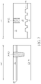
- FIG. 2 illustrates cross-section views of FIG. 1 along the sectional line AA′ and sectional line BB′.
- FIG. 3 illustrates a method for fabricating a semiconductor device according to an embodiment of the present invention following FIG. 2 .
- FIG. 4 is a top view illustrating a method for fabricating a semiconductor device according to an embodiment of the present invention following FIG. 1 ,
- FIG. 5 illustrates cross-section views of FIG. 4 along the sectional line CC′ and sectional line DD′.
- FIG. 6 is a top view illustrating a method for fabricating a semiconductor device according to an embodiment of the present invention following FIG. 4 .
- FIG. 7 illustrates cross-section views of FIG. 6 along the sectional line EE′ and sectional line FF′.
- FIG. 8 illustrates a method for fabricating a semiconductor device according to an embodiment of the present invention following FIG. 7 .
- FIG. 9 is a top view illustrating a method for fabricating a semiconductor device according to an embodiment of the present invention following FIG. 6 .
- FIG. 10 illustrates cross-section views of FIG. 9 along the sectional line GG′ and sectional line HH′.
- FIG. 11 illustrates a method for fabricating a semiconductor device according to an embodiment of the present invention following FIG. 10 .
- FIG. 12 is a top view illustrating a method for fabricating a semiconductor device according to an embodiment of the present invention following FIG. 9 .
- FIG. 13 illustrates a cross-section view of FIG. 12 along the sectional line II′.
- FIG. 14 illustrates a cross-section view of FIG. 12 along the sectional line JJ′.
- FIG. 15 illustrates a cross-section view of FIG. 12 along the sectional line KK′.
- FIG. 1 is a top view illustrating a method for fabricating a semiconductor device according to an embodiment of the present invention
- the left portion of FIG. 2 illustrates a cross-sectional view of FIG. 1 for fabricating the semiconductor device along the sectional line AA′
- the right portion of FIG. 2 illustrates a cross-sectional view of FIG. 1 for fabricating the semiconductor device along the sectional line BB′.
- a substrate 12 such as a silicon substrate or silicon-on-insulator (SOI) substrate is first provided, and a plurality of fin-shaped structures 14 extending along a first direction (such as the X-direction) are formed on the substrate 12 .
- a first direction such as the X-direction
- the fin-shaped structures 14 of this embodiment could be obtained by a sidewall image transfer (SIT) process.
- a layout pattern is first input into a computer system and is modified through suitable calculation.
- the modified layout is then defined in a mask and further transferred to a layer of sacrificial layer on a substrate through a photolithographic and an etching process.
- a deposition process and an etching process are carried out such that spacers are formed on the sidewalls of the patterned sacrificial layers.
- sacrificial layers can be removed completely by performing an etching process.
- the pattern defined by the spacers can be transferred into the substrate underneath, and through additional fin cut processes, desirable pattern structures, such as stripe patterned fin-shaped structures could be obtained.
- the bumps 16 protruding above the surface of the substrate 12 are preferably fin-shaped structures remained on the surface of the substrate 12 after the fin cut process is completed therefore the height of the bumps 16 are substantially lower than the height of the fin-shaped structures 14 on the left portion of FIG. 2 .
- the fin-shaped structures 14 could also be obtained by first forming a patterned mask (not shown) on the substrate, 12 , and through an etching process, the pattern of the patterned mask is transferred to the substrate 12 to form the fin-shaped structures 14 .
- the formation of the fin-shaped structures 14 could also be accomplished by first forming a patterned hard mask (not shown) on the substrate 12 , and a semiconductor layer composed of silicon germanium is grown from the substrate 12 through exposed patterned hard mask via selective epitaxial growth process to form the corresponding fin-shaped structures 14 .
- a shallow trench isolation (STI) 18 is formed around the fin-shaped structures 14 , such as surrounding the fin-shaped structures 14 in the left portion of FIG. 2 and disposed on top of the bumps 16 in the right portion of FIG. 2 .
- the formation of the STI 18 could be accomplished by conducting a flowable chemical vapor deposition (FCVD) process to form a silicon oxide layer on the substrate 12 and covering the fin-shaped structures 14 entirely.
- FCVD flowable chemical vapor deposition
- CMP chemical mechanical polishing
- a gate dielectric layer 20 and a gate layer 22 are formed to cover the fin-shaped structures 14 and the STI 18 entirely, and a patterned mask 24 is formed on the gate layer 22 , in which the patterned mask 22 includes an opening 26 exposing part of the gate layer 22 surface.
- the gate dielectric layer 20 preferably includes silicon oxide and the gate layer 22 is selected from the group consisting of amorphous silicon and polysilicon.
- the patterned mask 24 could additionally include an organic dielectric layer (ODL), a silicon-containing hard mask bottom anti-reflective coating (SHB), and a patterned resist and the step of forming the opening 26 in the patterned mask 24 could be accomplished by using the patterned resist as mask to remove part of the SHB and part of the ODL.
- ODL organic dielectric layer
- SHB silicon-containing hard mask bottom anti-reflective coating
- an etching process is conducted by using the patterned mask 24 as mask to remove part of the gate layer 22 , part of the gate dielectric layer 20 , and part of the fin-shaped structures 14 to form a first trench 28 and at the same time divide the fin-shaped structures 14 into two portions including a first portion 30 on the left side of the first trench 28 and a second portion 32 on the right side of the first trench 28 , in which the first trench 28 preferably extends along a second direction (such as Y-direction) orthogonal to the first direction.
- a second direction such as Y-direction
- FIG. 4 is a top view illustrating a method for fabricating a semiconductor device according to an embodiment of the present invention following FIG. 1
- the left portion of FIG. 5 illustrates a cross-sectional view of FIG. 4 for fabricating the semiconductor device along the sectional line CC′
- the right portion of FIG. 5 illustrates a cross-sectional view of FIG. 4 for fabricating the semiconductor device along the sectional line DD′.
- FIGS. 4 - 5 is a top view illustrating a method for fabricating a semiconductor device according to an embodiment of the present invention following FIG. 1
- the left portion of FIG. 5 illustrates a cross-sectional view of FIG. 4 for fabricating the semiconductor device along the sectional line CC′
- the right portion of FIG. 5 illustrates a cross-sectional view of FIG. 4 for fabricating the semiconductor device along the sectional line DD′.
- the patterned mask 34 preferably includes an opening extending along the first direction (such as X-direction) and exposing part of the gate layer 22 between the top four fin-shaped structures 14 and the bottom four fin-shaped structures 14 .
- the patterned mask 34 is used as a mask to remove part of the gate layer 22 and exposing the STI 18 underneath to form a second trench 36 , in which the second trench 36 preferably extends along the first direction between the top four fin-shaped structures 14 and bottom four fin-shaped structures 14 as shown in FIG. 4 .
- FIG. 6 is a top view illustrating a method for fabricating a semiconductor device according to an embodiment of the present invention following FIG. 4
- the left portion of FIG. 7 illustrates a cross-sectional view of FIG. 6 for fabricating the semiconductor device along the sectional line EE′
- the right portion of FIG. 7 illustrates a cross-sectional view of FIG. 6 for fabricating the semiconductor device along the sectional line FF′.
- a planarizing process such as chemical mechanical polishing (CMP) process is conducted to remove part of the dielectric layer 38 so that the top surface of the remaining dielectric layer 38 is even with the top surface of the gate layer 22 .
- CMP chemical mechanical polishing
- the SDB structure 40 and gate isolation structure 42 made of dielectric layer 38 could include same material or different material as the STI 18 .
- the SDB structure 40 and the gate isolation structure 42 in this embodiment could include but not limited to for example silicon oxide, silicon nitride (SiN), and/or silicon oxynitride (SiON).
- a hard mask 44 is formed on the gate layer 22 , the SDB structure 40 , and the gate isolation structure 42 , and a patterned mask 46 is formed on the hard mask 44 while exposing part of the hard mask 44 surface.
- the hard mask 44 preferably includes a composite structure such as a hard mask 48 and another hard mask 50 , in which the hard mask 48 and the hard mask 50 are preferably made of different materials.
- the hard mask 48 is preferably made of SiN while the hard mask 50 is made of silicon oxide, but not limited thereto.
- the patterned mask 46 could include a single patterned resist or could be made of same material as the patterned mask 24 shown in FIG. 2 .
- the patterned mask 46 could include a tri-layer structure having an organic dielectric layer (ODL), a silicon-containing hard mask bottom anti-reflective coating (SHB), and a patterned resist, which are all within the scope of the present invention.
- ODL organic dielectric layer
- SHB silicon-containing hard mask bottom anti-reflective coating
- FIG. 9 is a top view illustrating a method for fabricating a semiconductor device according to an embodiment of the present invention following FIG. 6
- the left portion of FIG. 10 illustrates a cross-sectional view of FIG. 9 for fabricating the semiconductor device along the sectional line GG′
- the right portion of FIG. 10 illustrates a cross-sectional view of FIG. 9 for fabricating the semiconductor device along the sectional line HH′.
- FIGS. 9 - 10 is a top view illustrating a method for fabricating a semiconductor device according to an embodiment of the present invention following FIG. 6
- the left portion of FIG. 10 illustrates a cross-sectional view of FIG. 9 for fabricating the semiconductor device along the sectional line GG′
- the right portion of FIG. 10 illustrates a cross-sectional view of FIG. 9 for fabricating the semiconductor device along the sectional line HH′.
- the patterned mask 46 is then used as mask to remove part of the hard mask 44 , part of the gate layer 22 , and part of the gate dielectric layer 20 to form a plurality of gate electrode or gate structures 52 , 54 extending along the second direction (or Y-direction) and standing astride on the fin-shaped structures 14 , in which the patterned hard mask 44 is disposed on each of the gate electrode or gate structures 52 , 54 .
- a gate isolation structures 42 has already been formed between the top four fin-shaped structures 14 and the bottom four fin-shaped structures 14 before the patterned mask 46 is formed, four separate gate structures 52 , 54 not contacting each other are automatically formed when the patterned mask 46 is used as mask to remove part of the hard mask 44 and part of the gate layer 22 for defining the pattern of the gate structures 52 , 54 .
- the patterned mask 46 is used as mask to remove part of the hard mask 44 and part of the gate layer 22 to form gate structures 52 , 54
- part of the SDB structures 40 and/or gate isolation structure 42 could also be removed to obtain lower heights.
- the tip or topmost surfaces of the SDB structure 40 and the gate isolation structure 42 are preferably lower than the topmost surface of the gate structures 52 , 54 or gate electrodes including the gate dielectric layer 20 and the gate layer 22 , in which the SDB structure 40 preferably protrudes above the fin-shaped structure 14 surface, the gate isolation structure 42 is disposed on the STI 18 , and the top surfaces of the SDB structure 40 and the gate isolation structure 42 are coplanar.
- a cap layer could be formed on the fin-shaped structures 14 to cover the gate structures 52 , 54 , the SDB structure 40 , and the gate isolation structure 42 , and an etching process is conducted to remove part of the cap layer for forming at least a spacer 56 adjacent to the sidewalls of the gate structure 42 and at the same time forming a spacer 58 on the sidewalls of the SDB structure 40 and a spacer 60 on sidewalls of the gate isolation structure 42 .
- each of the spacers 56 , 58 , 60 could be a single spacer or a composite spacer, such as a spacer including but not limited to for example an offset spacer and a main spacer.
- the offset spacer and the main spacer could include same material or different material while both the offset spacer and the main spacer could be made of material including but not limited to for example SiO 2 , SiN, SiON, SiCN, or combination thereof.
- the source/drain regions 62 could include dopants of different conductive type depending on the type of device being fabricated.
- a contact etch stop layer (CESL) 66 is formed on the surface of the fin-shaped structures 14 and covering the gate structure 52 , 54 , the SDB structure 40 , and the gate isolation structure 42 , and an interlayer dielectric (ILD) layer 68 is formed on the CESL 66 .
- a planarizing process such as CMP is conducted to remove part of the ILD layer 68 and part of the CESL 66 for exposing the hard mask 44 so that the top surfaces of the hard mask 44 and the ILD layer 68 are coplanar.
- FIG. 12 is a top view illustrating a method for fabricating a semiconductor device according to an embodiment of the present invention following FIG. 9
- FIG. 13 illustrates a cross-sectional view of FIG. 12 for fabricating the semiconductor device along the sectional line II′
- FIG. 14 illustrates a cross-sectional view of FIG. 12 for fabricating the semiconductor device along the sectional line JJ′
- FIG. 15 illustrates a cross-sectional view of FIG. 12 for fabricating the semiconductor device along the sectional line KK′.
- a replacement metal gate (RMG) process is conducted to transform the gate structure 52 , 54 into metal gates.
- RMG replacement metal gate
- the RMG process could be accomplished by first performing a selective dry etching or wet etching process using etchants including but not limited to for example ammonium hydroxide (NH 4 OH) or tetramethylammonium hydroxide (TMAH) to remove the second hard mask 44 , the gate layer 22 , and even gate dielectric layer 20 from gate structures 52 , 54 for forming recesses (not shown) in the ILD layer 68 .
- etchants including but not limited to for example ammonium hydroxide (NH 4 OH) or tetramethylammonium hydroxide (TMAH)
- a selective interfacial layer 70 or gate dielectric layer (not shown), a high-k dielectric layer 72 , a work function metal layer 74 , and a low resistance metal layer 76 are formed in the recess, and a planarizing process such as CMP is conducted to remove part of low resistance metal layer 76 , part of work function metal layer 74 , and part of high-k dielectric layer 72 to form metal gates 78 .
- the gate structure or metal gate 78 fabricated through high-k last process of a gate last process preferably includes an interfacial layer 70 or gate dielectric layer (not shown), a U-shaped high-k dielectric layer 72 , a U-shaped work function metal layer 74 , and a low resistance metal layer 76 .
- the high-k dielectric layer 72 is preferably selected from dielectric materials having dielectric constant (k value) larger than 4 .
- the high-k dielectric layer 72 may be selected from hafnium oxide (HfO 2 ), hafnium silicon oxide (HfSiO 4 ), hafnium silicon oxynitride (HfSiON), aluminum oxide (Al 2 O 3 ), lanthanum oxide (La 2 O 3 ), tantalum oxide (Ta 2 O 5 ), yttrium oxide (Y 2 O 3 ), zirconium oxide (ZrO 2 ), strontium titanate oxide (SrTiO 3 ), zirconium silicon oxide (ZrSiO 4 ), hafnium zirconium oxide (HfZrO 4 ), strontium bismuth tantalate (SrBi 2 Ta 2 O 9 , SBT), lead zirconate titanate (PbZr x Ti 1-x O 3 , PZT), barium strontium titanate (Pb
- the work function metal layer 74 is formed for tuning the work function of the metal gate in accordance with the conductivity of the device.
- the work function metal layer 74 having a work function ranging between 3.9 eV and 4.3 eV may include titanium aluminide (TiAl), zirconium aluminide (ZrAl), tungsten aluminide (WAl), tantalum aluminide (TaAl), hafnium aluminide (HfAl), or titanium aluminum carbide (TiAlC), but it is not limited thereto.
- the work function metal layer 74 having a work function ranging between 4.8 eV and 5.2 eV may include titanium nitride (TiN), tantalum nitride (TaN), tantalum carbide (TaC), but it is not limited thereto.
- An optional barrier layer (not shown) could be formed between the work function metal layer 74 and the low resistance metal layer 76 , in which the material of the barrier layer may include titanium (Ti), titanium nitride (TiN), tantalum (Ta) or tantalum nitride (TaN).
- the material of the low-resistance metal layer 76 may include copper (Cu), aluminum (Al), titanium aluminum (TiAl), cobalt tungsten phosphide (CoWP) or any combination thereof.
- a pattern transfer process is conducted by using a patterned mask (not shown) as mask to remove part of the ILD layer 68 and part of the CESL 66 adjacent to the metal gates 78 and SDB structure 40 for forming contact holes (not shown) exposing the source/drain regions 62 underneath.
- metals including a barrier layer selected from the group consisting of Ti, TiN, Ta, and TaN and a low resistance metal layer selected from the group consisting of W, Cu, Al, TiAl, and CoWP are deposited into the contact holes, and a planarizing process such as CMP is conducted to remove part of aforementioned barrier layer and low resistance metal layer for forming contact plugs 82 electrically connecting the source/drain regions 62 .
- the hard mask 44 made of hard masks 48 , 50 are formed on the surface of the gate layer 22 after the SDB structure 40 and gate isolation structure 42 are formed as shown in FIG. 8 , according to an embodiment of the present invention, it would also be desirable to form at least a hard mask such as a hard mask 48 made of silicon nitride on the surface of the gate layer 22 before forming the patterned mask 24 as shown in FIG. 2 , and then forming the patterned mask 24 on the surface of the hard mask before continue with the follow-up process.
- a hard mask such as a hard mask 48 made of silicon nitride
- the patterned mask 24 could then be used as mask to remove part of the hard mask, part of the gate layer 22 , part of the gate dielectric layer 20 , and part of the fin-shaped structures 14 to form the first trench 28 used for preparing the SDB structure 40 , which is also within the scope of the present invention.
- FIG. 14 illustrates a structural view of a semiconductor device according to an embodiment of the present invention.
- the semiconductor device preferably includes a gate isolation structure 42 disposed on the STI 18 , a spacer 60 around the gate isolation structure 42 , epitaxial layer 64 disposed on one side of the gate isolation structure 42 , another epitaxial layer 64 disposed on another side of the gate isolation structure 42 , a plurality of fin-shaped structures 14 disposed under the epitaxial layers 64 , a CESL 66 disposed on the surface of the gate isolation structure 42 , the STI 18 , and part of the epitaxial layers 64 , an ILD layer 68 disposed on the CESL 66 , and contact plugs 82 disposed adjacent to two sides of the gate isolation structure 42 and on the epitaxial layers 64 .
- the gate isolation structure 42 and the STI 18 could be made of same material or different materials, in which the gate isolation structure 42 could include but not limited to for example SiO 2 , SiN, or SiON.
- the top or topmost surface of the gate isolation structure 42 is even with the top or topmost surface of the adjacent epitaxial layers 64 , according to other embodiments of the present invention, the topmost surface of the gate isolation structure 42 could also be slightly higher than or slightly lower than the topmost surface of the epitaxial layers 64 on the two sides, which is also within the scope of the present invention.
- FIG. 15 illustrates a structural view of a semiconductor device according to an embodiment of the present invention.
- the semiconductor device preferably includes a gate structure 52 and gate structure 54 disposed on the STI 18 , a hard mask 80 disposed on each of the gate structures 52 , 54 , a gate isolation structures 42 disposed between the two gate structures 52 , 54 , spacers 60 disposed adjacent to the gate structures 52 , 54 and directly on the gate isolation structure 42 , a CESL 66 disposed on the gate isolation structure 42 and between the two spacers 60 , and an ILD layer 68 disposed on the CESL 66 , in which the top surfaces of the ILD layer 68 and the hard mask 80 are coplanar.
- the top or topmost surface of the gate isolation structure 42 is preferably lower than the topmost surface of the gate structures 52 , 54 or gate electrodes adjacent to two sides of the gate isolation structure 42 , the sidewalls of the gate isolation structure 42 are aligned with sidewalls of the hard masks 80 , the gate structures 52 , 54 contact the gate isolation structure 42 directly, the spacers 60 are disposed on sidewalls of the hard mask 80 and gate structures 52 , 54 while the bottom or bottommost surface of the spacers 60 are slightly higher than the bottommost surface of the gate structures 52 , 54 but slightly lower than the topmost surface of the gate structures 52 , 54 , the bottom surface of the spacers 60 contact the gate isolation structure 42 directly, the CESL 66 contacts the spacers 60 and the gate isolation structure 42 directly, the CESL 66 preferably includes a U-shaped cross-section, and the top surfaces of the ILD layer 68 , the CESL 66 , and the hard mask 80 are coplanar.
Abstract
Description
Claims (9)
Priority Applications (2)
| Application Number | Priority Date | Filing Date | Title |
|---|---|---|---|
| US17/161,696 US11527638B2 (en) | 2019-04-01 | 2021-01-29 | Semiconductor device and method for fabricating the same |
| US17/983,417 US20230066954A1 (en) | 2019-04-01 | 2022-11-09 | Semiconductor device and method for fabricating the same |
Applications Claiming Priority (4)
| Application Number | Priority Date | Filing Date | Title |
|---|---|---|---|
| CN201910256992.7 | 2019-04-01 | ||
| CN201910256992.7A CN111769045B (en) | 2019-04-01 | 2019-04-01 | Semiconductor element and manufacturing method thereof |
| US16/396,777 US10943993B2 (en) | 2019-04-01 | 2019-04-29 | Semiconductor device and method for fabricating the same |
| US17/161,696 US11527638B2 (en) | 2019-04-01 | 2021-01-29 | Semiconductor device and method for fabricating the same |
Related Parent Applications (1)
| Application Number | Title | Priority Date | Filing Date |
|---|---|---|---|
| US16/396,777 Division US10943993B2 (en) | 2019-04-01 | 2019-04-29 | Semiconductor device and method for fabricating the same |
Related Child Applications (1)
| Application Number | Title | Priority Date | Filing Date |
|---|---|---|---|
| US17/983,417 Continuation US20230066954A1 (en) | 2019-04-01 | 2022-11-09 | Semiconductor device and method for fabricating the same |
Publications (2)
| Publication Number | Publication Date |
|---|---|
| US20210159322A1 US20210159322A1 (en) | 2021-05-27 |
| US11527638B2 true US11527638B2 (en) | 2022-12-13 |
Family
ID=70058101
Family Applications (5)
| Application Number | Title | Priority Date | Filing Date |
|---|---|---|---|
| US16/396,777 Active US10943993B2 (en) | 2019-04-01 | 2019-04-29 | Semiconductor device and method for fabricating the same |
| US17/161,696 Active 2039-08-18 US11527638B2 (en) | 2019-04-01 | 2021-01-29 | Semiconductor device and method for fabricating the same |
| US17/161,707 Active 2039-09-08 US11581422B2 (en) | 2019-04-01 | 2021-01-29 | Semiconductor device and method for fabricating the same |
| US17/983,417 Pending US20230066954A1 (en) | 2019-04-01 | 2022-11-09 | Semiconductor device and method for fabricating the same |
| US18/093,330 Pending US20230143927A1 (en) | 2019-04-01 | 2023-01-05 | Semiconductor device and method for fabricating the same |
Family Applications Before (1)
| Application Number | Title | Priority Date | Filing Date |
|---|---|---|---|
| US16/396,777 Active US10943993B2 (en) | 2019-04-01 | 2019-04-29 | Semiconductor device and method for fabricating the same |
Family Applications After (3)
| Application Number | Title | Priority Date | Filing Date |
|---|---|---|---|
| US17/161,707 Active 2039-09-08 US11581422B2 (en) | 2019-04-01 | 2021-01-29 | Semiconductor device and method for fabricating the same |
| US17/983,417 Pending US20230066954A1 (en) | 2019-04-01 | 2022-11-09 | Semiconductor device and method for fabricating the same |
| US18/093,330 Pending US20230143927A1 (en) | 2019-04-01 | 2023-01-05 | Semiconductor device and method for fabricating the same |
Country Status (3)
| Country | Link |
|---|---|
| US (5) | US10943993B2 (en) |
| EP (1) | EP3719836A3 (en) |
| CN (1) | CN111769045B (en) |
Cited By (1)
| Publication number | Priority date | Publication date | Assignee | Title |
|---|---|---|---|---|
| US20230066954A1 (en) * | 2019-04-01 | 2023-03-02 | United Microelectronics Corp. | Semiconductor device and method for fabricating the same |
Families Citing this family (2)
| Publication number | Priority date | Publication date | Assignee | Title |
|---|---|---|---|---|
| US20220336473A1 (en) * | 2021-04-14 | 2022-10-20 | Samsung Electronics Co., Ltd. | Selective double diffusion break structures for multi-stack semiconductor device |
| KR20230001918A (en) | 2021-06-29 | 2023-01-05 | 삼성전자주식회사 | Semiconductor device |
Citations (7)
| Publication number | Priority date | Publication date | Assignee | Title |
|---|---|---|---|---|
| US20140027820A1 (en) | 2012-07-24 | 2014-01-30 | International Business Machines Corporation | Forming facet-less epitaxy with self-aligned isolation |
| US20150054078A1 (en) | 2013-08-21 | 2015-02-26 | International Business Machines Corporation | Methods of forming gate structures for finfet devices and the resulting smeiconductor products |
| US9524911B1 (en) | 2015-09-18 | 2016-12-20 | Globalfoundries Inc. | Method for creating self-aligned SDB for minimum gate-junction pitch and epitaxy formation in a fin-type IC device |
| US20170271503A1 (en) | 2012-01-23 | 2017-09-21 | Taiwan Semiconductor Manufacturing Company, Ltd. | Structure and method for providing line end extensions for fin-type active regions |
| EP3288085A1 (en) | 2016-08-23 | 2018-02-28 | Semiconductor Manufacturing International Corporation (Shanghai) | Semiconductor structure and fabrication method thereof |
| US9953880B1 (en) | 2017-06-29 | 2018-04-24 | United Microelectronics Corp. | Semiconductor device and method for fabricating the same |
| US10943993B2 (en) * | 2019-04-01 | 2021-03-09 | United Microelectronics Corp. | Semiconductor device and method for fabricating the same |
Family Cites Families (2)
| Publication number | Priority date | Publication date | Assignee | Title |
|---|---|---|---|---|
| TWI729181B (en) * | 2017-08-03 | 2021-06-01 | 聯華電子股份有限公司 | Semiconductor device and method for fabricating the same |
| US10403714B2 (en) * | 2017-08-29 | 2019-09-03 | Taiwan Semiconductor Manufacturing Co., Ltd. | Fill fins for semiconductor devices |
-
2019
- 2019-04-01 CN CN201910256992.7A patent/CN111769045B/en active Active
- 2019-04-29 US US16/396,777 patent/US10943993B2/en active Active
-
2020
- 2020-03-27 EP EP20166214.5A patent/EP3719836A3/en active Pending
-
2021
- 2021-01-29 US US17/161,696 patent/US11527638B2/en active Active
- 2021-01-29 US US17/161,707 patent/US11581422B2/en active Active
-
2022
- 2022-11-09 US US17/983,417 patent/US20230066954A1/en active Pending
-
2023
- 2023-01-05 US US18/093,330 patent/US20230143927A1/en active Pending
Patent Citations (7)
| Publication number | Priority date | Publication date | Assignee | Title |
|---|---|---|---|---|
| US20170271503A1 (en) | 2012-01-23 | 2017-09-21 | Taiwan Semiconductor Manufacturing Company, Ltd. | Structure and method for providing line end extensions for fin-type active regions |
| US20140027820A1 (en) | 2012-07-24 | 2014-01-30 | International Business Machines Corporation | Forming facet-less epitaxy with self-aligned isolation |
| US20150054078A1 (en) | 2013-08-21 | 2015-02-26 | International Business Machines Corporation | Methods of forming gate structures for finfet devices and the resulting smeiconductor products |
| US9524911B1 (en) | 2015-09-18 | 2016-12-20 | Globalfoundries Inc. | Method for creating self-aligned SDB for minimum gate-junction pitch and epitaxy formation in a fin-type IC device |
| EP3288085A1 (en) | 2016-08-23 | 2018-02-28 | Semiconductor Manufacturing International Corporation (Shanghai) | Semiconductor structure and fabrication method thereof |
| US9953880B1 (en) | 2017-06-29 | 2018-04-24 | United Microelectronics Corp. | Semiconductor device and method for fabricating the same |
| US10943993B2 (en) * | 2019-04-01 | 2021-03-09 | United Microelectronics Corp. | Semiconductor device and method for fabricating the same |
Cited By (1)
| Publication number | Priority date | Publication date | Assignee | Title |
|---|---|---|---|---|
| US20230066954A1 (en) * | 2019-04-01 | 2023-03-02 | United Microelectronics Corp. | Semiconductor device and method for fabricating the same |
Also Published As
| Publication number | Publication date |
|---|---|
| CN111769045B (en) | 2024-04-02 |
| EP3719836A3 (en) | 2020-12-09 |
| US20210159322A1 (en) | 2021-05-27 |
| US10943993B2 (en) | 2021-03-09 |
| US20210167189A1 (en) | 2021-06-03 |
| US20200312984A1 (en) | 2020-10-01 |
| EP3719836A2 (en) | 2020-10-07 |
| US11581422B2 (en) | 2023-02-14 |
| US20230066954A1 (en) | 2023-03-02 |
| CN111769045A (en) | 2020-10-13 |
| US20230143927A1 (en) | 2023-05-11 |
Similar Documents
| Publication | Publication Date | Title |
|---|---|---|
| US10679903B2 (en) | Semiconductor device and method for fabricating the same | |
| US11417564B2 (en) | Semiconductor device and method for fabricating the same | |
| US10141228B1 (en) | FinFET device having single diffusion break structure | |
| US11901239B2 (en) | Semiconductor device and method for fabricating the same | |
| US10522660B2 (en) | Method for fabricating semiconductor device | |
| US10892194B2 (en) | Semiconductor device and method for fabricating the same | |
| US11527638B2 (en) | Semiconductor device and method for fabricating the same | |
| US20230386939A1 (en) | Semiconductor device and method for fabricating the same | |
| US11011430B2 (en) | Semiconductor device and method for fabricating the same | |
| US20240128127A1 (en) | Semiconductor device and method for fabricating the same |
Legal Events
| Date | Code | Title | Description |
|---|---|---|---|
| FEPP | Fee payment procedure |
Free format text: ENTITY STATUS SET TO UNDISCOUNTED (ORIGINAL EVENT CODE: BIG.); ENTITY STATUS OF PATENT OWNER: LARGE ENTITY |
|
| STPP | Information on status: patent application and granting procedure in general |
Free format text: APPLICATION DISPATCHED FROM PREEXAM, NOT YET DOCKETED |
|
| STPP | Information on status: patent application and granting procedure in general |
Free format text: DOCKETED NEW CASE - READY FOR EXAMINATION |
|
| STPP | Information on status: patent application and granting procedure in general |
Free format text: EX PARTE QUAYLE ACTION MAILED |
|
| STPP | Information on status: patent application and granting procedure in general |
Free format text: RESPONSE TO EX PARTE QUAYLE ACTION ENTERED AND FORWARDED TO EXAMINER |
|
| STPP | Information on status: patent application and granting procedure in general |
Free format text: NOTICE OF ALLOWANCE MAILED -- APPLICATION RECEIVED IN OFFICE OF PUBLICATIONS |
|
| STPP | Information on status: patent application and granting procedure in general |
Free format text: PUBLICATIONS -- ISSUE FEE PAYMENT VERIFIED |
|
| STCF | Information on status: patent grant |
Free format text: PATENTED CASE |