US11524617B2 - Device for adjusting a height of a mono-post type headrest for a vehicle - Google Patents
Device for adjusting a height of a mono-post type headrest for a vehicle Download PDFInfo
- Publication number
- US11524617B2 US11524617B2 US17/327,237 US202117327237A US11524617B2 US 11524617 B2 US11524617 B2 US 11524617B2 US 202117327237 A US202117327237 A US 202117327237A US 11524617 B2 US11524617 B2 US 11524617B2
- Authority
- US
- United States
- Prior art keywords
- locking
- mono
- post
- lever
- front cover
- Prior art date
- Legal status (The legal status is an assumption and is not a legal conclusion. Google has not performed a legal analysis and makes no representation as to the accuracy of the status listed.)
- Active
Links
Images


Classifications
-
- B—PERFORMING OPERATIONS; TRANSPORTING
- B60—VEHICLES IN GENERAL
- B60N—SEATS SPECIALLY ADAPTED FOR VEHICLES; VEHICLE PASSENGER ACCOMMODATION NOT OTHERWISE PROVIDED FOR
- B60N2/00—Seats specially adapted for vehicles; Arrangement or mounting of seats in vehicles
- B60N2/80—Head-rests
- B60N2/806—Head-rests movable or adjustable
- B60N2/809—Head-rests movable or adjustable vertically slidable
- B60N2/812—Head-rests movable or adjustable vertically slidable characterised by their locking devices
- B60N2/818—Head-rests movable or adjustable vertically slidable characterised by their locking devices with stepwise positioning
-
- B—PERFORMING OPERATIONS; TRANSPORTING
- B60—VEHICLES IN GENERAL
- B60N—SEATS SPECIALLY ADAPTED FOR VEHICLES; VEHICLE PASSENGER ACCOMMODATION NOT OTHERWISE PROVIDED FOR
- B60N2/00—Seats specially adapted for vehicles; Arrangement or mounting of seats in vehicles
- B60N2/80—Head-rests
- B60N2/806—Head-rests movable or adjustable
- B60N2/809—Head-rests movable or adjustable vertically slidable
- B60N2/812—Head-rests movable or adjustable vertically slidable characterised by their locking devices
- B60N2/815—Release mechanisms, e.g. buttons
-
- B—PERFORMING OPERATIONS; TRANSPORTING
- B60—VEHICLES IN GENERAL
- B60N—SEATS SPECIALLY ADAPTED FOR VEHICLES; VEHICLE PASSENGER ACCOMMODATION NOT OTHERWISE PROVIDED FOR
- B60N2/00—Seats specially adapted for vehicles; Arrangement or mounting of seats in vehicles
- B60N2/80—Head-rests
- B60N2/806—Head-rests movable or adjustable
- B60N2/809—Head-rests movable or adjustable vertically slidable
- B60N2/812—Head-rests movable or adjustable vertically slidable characterised by their locking devices
- B60N2/821—Head-rests movable or adjustable vertically slidable characterised by their locking devices with continuous positioning
- B60N2/824—Head-rests movable or adjustable vertically slidable characterised by their locking devices with continuous positioning using springs
-
- B—PERFORMING OPERATIONS; TRANSPORTING
- B60—VEHICLES IN GENERAL
- B60N—SEATS SPECIALLY ADAPTED FOR VEHICLES; VEHICLE PASSENGER ACCOMMODATION NOT OTHERWISE PROVIDED FOR
- B60N2/00—Seats specially adapted for vehicles; Arrangement or mounting of seats in vehicles
- B60N2/80—Head-rests
- B60N2/894—Head-rests with rods solidly attached to the back-rest
Definitions
- the present disclosure relates to a device for adjusting the height of a mono-post type headrest for a vehicle, and more specifically, to a device for adjusting the height of a mono-post type headrest for a vehicle, which may easily adjust the height of a mono-post type headrest for a vehicle by only an operation of a lever.
- a seat for a vehicle is configured to include a seat cushion for seating the lower body of a passenger, a seatback for contacting the waist and back area of the passenger, and a headrest mounted on the upper portion of the seatback to be adjustable in height.
- a pair of stays 12 inserted into a seatback frame 20 to be adjustable in height are mounted on the bottom of the headrest 10 .
- the upper end of the seatback has a pole guide device 30 mounted for the elevating guidance of the stay 12 s.
- each stay 12 is formed with a plurality of locking grooves 14 and the respective pole guide device 30 is mounted with a push-pull type locking lever 32 .
- the height of the stays 12 may be adjusted to the desired height.
- the design of such a headrest and a device for adjusting the height thereof are generally adopted but is not suitable for the design and concept of the seat for a future vehicle such as an autonomous vehicle.
- the design of the headrest of a new paradigm is required, and as an example, may be a mono-post type headrest.
- An object of the present disclosure is to provide a device for adjusting the height of a mono-post type headrest for a vehicle.
- the device may mount a headrest on a mono-post mounted on a seatback frame to be adjustable in height.
- the device may include a lever mounted on one side of the headrest, thereby easily adjusting the headrest to the desired height by only a flipping operation for the locking release of the lever.
- the present disclosure provides a device for adjusting the height of a mono-post type headrest for a vehicle.
- the device includes: a mono-post provided in a structure mounted on a seatback frame and in which a plurality of locking holes are vertically formed at a predetermined interval; a front cover fastened to the mono-post to move up and down; a lever flippably mounted at a location on one side of the front cover; a locking device connected to the lever and mounted on a back surface of the front cover, the locking device configured to be locked and fastened to any one locking hole of the plurality of locking holes of the mono-post, or unlocked by being released from the one locking hole of the mono-post in conjunction with a flipping operation of the lever; a middle cover covering the locking device and the mono-post and mounted on the back surface of the front cover; and a rear cover covering the middle cover and assembled to the back surface of the front cover.
- the locking device is configured to include: a shaft contacting an inner portion of the lever and disposed on the back surface of the front cover to be laterally transportable; a lock plate provided in a flat structure in which a guide hole is formed to pass through, the lock plate connected to an inner end portion of the shaft and disposed on the back surface of the front cover to be laterally transportable; and a locking bracket provided in a structure having a locking end inserted into the one locking hole of the mono-post on the back surface thereof.
- the locking bracket is formed with a lock pin inserted into the guide hole of the lock plate on an upper surface thereof and rotatably fastened to the back surface of the front cover.
- the locking device is configured to further include: a rotary shaft formed on a lower end of the locking bracket and connected to the back surface of the front cover; and a return spring mounted on the rotary shaft to provide an elastic restoring force upon rotation of the locking bracket.
- the lever is composed of a user operating lever configured to be flipped by a user and a flipping force delivery lever fastened to the user operating lever by a hinge pin to contact an outer surface of the shaft.
- the lock pin is located at an innermost location in a slope section of the guide hole and the locking end of the locking bracket is locked to and inserted into the one locking hole of the mono-post by an elastic restoring force of a return spring.
- the locking device is configured to include: a cable connected to an inner portion of the lever; a lock plate provided in a flat structure having a guide hole with an inclined slope formed therethrough, the lock plate connected to an inner end of the cable and disposed on the back surface of the front cover to be laterally transportable; and a locking bracket provided in a structure having a locking end inserted into the one locking hole of the mono-post on the back surface thereof and formed with a lock pin inserted into the guide hole of the lock plate on the upper surface thereof, and rotatably fastened to the back surface of the front cover.
- the locking device is configured to further include: a rotary shaft formed on a lower end of the locking bracket and connected to the back surface of the front cover; and a return spring mounted on the rotary shaft to provide an elastic restoring force upon rotation of the locking bracket.
- the lock pin is located at an innermost location in a slope section of the guide hole, and the locking end of the locking bracket is locked to and inserted into the one locking hole of the mono-post by an elastic restoring force of a return spring.
- the back surface of the front cover is mounted with a plurality of guiding rollers contacting both side surfaces of the mono-post so as to be rollable.
- the back surface of the rear cover is attached with a back cover for a garnish function.
- the front surface of the front cover is attached with a pad covered by the cover.
- a hybrid vehicle is a vehicle that has two or more sources of power, for example vehicles that are both gasoline-powered and electric-powered.
- FIG. 1 is a schematic diagram illustrating a conventional device for adjusting the height of a headrest.
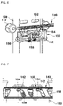
- FIGS. 2 and 3 are perspective diagrams illustrating the appearance of a mono-post type headrest for a vehicle according to the present disclosure.
- FIG. 4 is an exploded perspective diagram illustrating the mono-post type headrest for the vehicle and a device for adjusting the height thereof according to the present disclosure.
- FIGS. 5 A and 5 B are rear view diagrams illustrating the device for adjusting the height of the mono-post type headrest for the vehicle according to the present disclosure.
- FIG. 6 is a perspective front view diagram illustrating a lock plate and a locking bracket among the components of the device for adjusting the height of the mono-post type headrest for the vehicle according to the present disclosure.
- FIG. 7 is a perspective top view diagram illustrating a state before operation of the lock plate and the locking bracket among the components of the device for adjusting the height of the mono-post type headrest for the vehicle according to the present disclosure.
- FIG. 8 is a plan view diagram illustrating a flipping state of a lever among the components of the device for adjusting the height of the mono-post type headrest for the vehicle according to the present disclosure.
- FIG. 9 is a perspective top view diagram illustrating a state after operation of the lock plate and the locking bracket among the components of the device for adjusting the height of the mono-post type headrest for the vehicle according to the present disclosure.
- FIG. 10 is a cross-sectional diagram illustrating the state before and after operation of the lock plate and the locking bracket among the components of the device for adjusting the height of the mono-post type headrest for the vehicle according to the present disclosure.
- FIG. 11 is a perspective diagram illustrating a state before operation of another embodiment of a device for adjusting the height of the mono-post type headrest for the vehicle according to the present disclosure.
- FIG. 12 is a plan diagram illustrating the state before the operation of another embodiment of the device for adjusting the height of the mono-post type headrest for the vehicle according to the present disclosure.
- FIG. 13 is a cross-sectional diagram illustrating the state before the operation of another embodiment of the device for adjusting the height of the mono-post type headrest for the vehicle according to the present disclosure.
- FIG. 14 is a perspective diagram illustrating a state after the operation of another embodiment of the device for adjusting the height of the mono-post type headrest for the vehicle according to the present disclosure.
- FIG. 15 is a plan view diagram illustrating the state after the operation of another embodiment of the device for adjusting the height of the mono-post type headrest for the vehicle according to the present disclosure.
- FIG. 16 is a cross-sectional diagram illustrating the state after the operation of another embodiment of the device for adjusting the height of the mono-post type headrest for the vehicle according to the present disclosure.
- FIGS. 2 - 4 illustrate a mono-post type headrest for a vehicle and a device for adjusting the height thereof according to the present disclosure.
- FIGS. 5 A and 5 B are rear view diagrams illustrating a front cover among the components of the device for adjusting the height of the mono-post type headrest according to the present disclosure viewed from the back.
- a mono-post 100 is mounted on a seatback frame 200 .
- the front surface of the mono-post 100 is formed with a plurality of locking holes 102 at a predetermined interval vertically in the longitudinal direction.
- the mono-post 100 has to adjacent vertical columns of the locking holes.
- a front cover 110 and a middle cover 160 are assembled to each other with the mono-post 100 interposed therebetween.
- the middle cover 160 covers the mono-post 100 and is assembled to the front cover 110 via a screw or the like.
- the back surface of the front cover 110 has two pairs of guiding rollers 112 .
- the guiding rollers 112 contact both side surfaces of the mono-post 100 to be rollable, i.e., to be capable of rolling along both side surfaces.
- the guiding rollers 112 perform the rolling motion along both side surfaces of the mono-post 100 , such that the front cover may easily move up and down.
- a lever 120 is mounted on one side location of the back surface of a rear cover 70 , which is located on the back of the front cover 110 .
- the lever 120 can be flipped between two positions, i.e., is flippably mounted on the one side of the rear cover 70 .
- the lever 120 has a user operating lever 122 configured to be flipped by the user.
- the lever 120 also has a flipping force delivery lever 124 that is fastened to the user operating lever 122 by a hinge pin and that contacts the outer surface of a shaft 130 among the components of a locking device.
- the flipping force delivery lever 124 pushes the shaft 130 while rotating in the same direction.
- the locking device including the shaft 130 , which interlocks with the lever 120 , is mounted on the back surface of the front cover 110 .
- the locking device may be configured as an operating mechanism mounted on the back surface of the front cover 110 .
- the locking device is configured to be locked and fastened to one locking hole of the plurality of locking holes 102 of the mono-post 100 or unlocked by being released from the one locking hole 102 of the mono-post 100 in conjunction with the flipping operation of the lever 120 .
- the locking device is configured to be locked and fastened to two laterally adjacent locking holes 102 , one in each of the two adjacent columns on the mono-post 100 .
- a configuration of the locking device according to an embodiment of the present disclosure is described as follows.
- the shaft 130 contacting the flipping force delivery lever 124 of the lever 120 is disposed on the back surface of the front cover 110 so as to be laterally transportable.
- a lock plate 140 connected to the inner end of the shaft 130 is disposed on the back surface of the front cover 110 so as to be laterally transportable.
- the lock plate 140 may be provided in a flat structure in which two or more curved guide holes 142 are formed to pass through the lock plate.
- the pass-through shape of the guide holes 142 may vary as long as it is sloped, i.e., an inclined shape regardless of being a straight line or a curve.
- a locking bracket 150 performing the rotating motion upon the linear motion of the lock plate 140 is rotatably fastened to the back surface of the front cover 110 .
- the locking bracket 150 is provided in a structure with a locking end 152 inserted into one of the locking holes 102 of each column of the mono-post 100 on the back surface thereof.
- the locking bracket 150 is formed with a lock pin 154 inserted into each of the guide holes 142 of the lock plate 140 on the upper surface thereof.
- the lower end of the locking bracket 150 is formed with a rotary shaft 156 connected to the back surface of the front cover 110 .
- a return spring 158 provides an elastic restoring force upon rotation of the locking bracket 150 and is inserted into and fastened to the rotary shaft 156 .
- the back surface of the front cover 110 is fastened to the middle cover 160 covering the lock plate 140 and the locking bracket 150 among the components of the locking device to prevent separation of the lock plate 140 and the locking bracket 150 .
- the back surface of the front cover 110 is fastened to a rear cover 170 covering the shaft 130 and the middle cover 160 .
- the lever 120 is flippably located at a location on one side of the back surface of the rear cover 170 .
- front surface of the front cover 110 is attached with a pad 190 covered by the cover substantially contacting the passenger's head, as illustrated in FIG. 2 .
- the back surface of the rear cover 170 is further attached with a back cover 180 for a garnish function.
- a process of adjusting the height of the headrest performed by the locking device according to the embodiment is described as follows.
- each lock pin 154 of the locking bracket 150 is located at the innermost location in the corresponding section of the respective guide hole 142 of the lock plate 140 .
- Each locking end 152 of the locking bracket 150 is maintained in the state of being locked to and inserted into the selected locking hole 102 of the mono-post 100 by the elastic restoring force of the return spring 158 .
- the headrest including the front cover 110 , the middle cover 160 , and the like is maintained in the fixed state.
- the flipping force delivery lever 124 which is fastened to the user operating lever 122 by the hinge pin, rotates to push the shaft 130 inward.
- each lock pin 154 of the locking bracket 150 moves along the corresponding curved or sloped surface of the respective guide hole 142 of the lock plate 140 to be located at the outermost location in the section of the guide hole 142 .
- the locking bracket 150 is rotated around the rotary shaft 156 , such that, as illustrated in FIG. 10 , each locking end 152 of the locking bracket 150 is unlocked by being released from the respective locking hole 102 of the mono-post 100 .
- the user may adjust the height of the headrest to the desired height while moving the headrest upward or downward.
- each locking end 152 of the locking bracket 150 is locked to and inserted into the selected locking hole 102 of the mono-post 100 again by the elastic restoring force of the return spring 158 , such that the headrest is then in a state of being fixed at the desired height.
- FIGS. 11 - 16 A configuration of the locking device according to another embodiment of the present disclosure is described with reference to FIGS. 11 - 16 as follows.
- a locking device is characterized in that the lever 120 and the lock plate 140 are connected by a cable 132 .
- the guide holes 146 have an inclined slope 144 formed on the lock plate 140 and the lock pins 154 of the locking bracket 150 are moved along the inclined slopes 144 .
- the lock plate 140 is disposed on the back surface of the front cover 110 so as to be laterally transportable. As illustrated in FIGS. 11 and 12 , the lock plate 140 has one end connected to the inner end of the cable 132 extending from the lever 120 .
- the lock plate 140 is provided in a flat structure in which the guide holes 146 with the inclined slopes 144 are formed through the lock plate 140 .
- the locking bracket 150 is provided in a structure with the locking end 152 inserted into the selected locking hole 102 of the mono-post 100 on the back surface thereof and with the lock pin 154 s inserted into the guide holes 146 of the lock plate 140 on the upper surface thereof, thereby being rotatably fastened to the back surface of the front cover 110 .
- the lower end of the locking bracket 150 is formed with the rotary shaft 156 connected to the back surface of the front cover 110 .
- the return spring 158 is configured to provide the elastic restoring force and is inserted into and fastened to the rotary shaft 156 upon rotation of the locking bracket 150 .
- a process of adjusting the height of the headrest performed by the locking device according to this embodiment is described as follows.
- each the lock pin 154 of the locking bracket 150 is located at the innermost location in the section of the corresponding inclined slope 144 formed in the respective guide hole 146 of the lock plate 140 .
- the locking end 152 of the locking bracket 150 is maintained in the state of being locked to and inserted into the locking hole 102 of the mono-post 100 by the elastic restoring force of the return spring 158 .
- the headrest including the front cover 110 , the middle cover 160 , and the like is maintained in the fixed state.
- each lock pin 154 of the locking bracket 150 moves along the corresponding inclined slope 144 of the respective guide hole 146 of the lock plate 140 to be located at the outermost location in the section of the guide hole 146 .
- the locking bracket 150 is rotated around the rotary shaft 156 , such that, as illustrated in FIG. 16 , the locking end 152 of the locking bracket 150 is unlocked by being released from the selected locking holes 102 of the mono-post 100 .
- the user may adjust the height of the headrest to the desired height while moving the headrest upward or downward.
- the locking end 152 of the locking bracket 150 is locked to and inserted into the locking hole 102 of the mono-post 100 again by the elastic restoring force of the return spring 158 , such that the headrest is in the state of being fixed at the desired height.
- the above embodiment may include only a single column of the plurality of locking holes 102 , one locking end 152 , one guide hole, and one lock pin 154 .
- a mono-post type headrest in which the headrest is mounted on the mono-post 100 , which is mounted on the seatback frame 200 to be adjustable in height, and more particularly, to easily adjust the up and down movement of the headrest along the mono-post to the desired height by only the flipping operation for unlocking the lever 120 , which is mounted on one side of the headrest.
Landscapes
- Engineering & Computer Science (AREA)
- Aviation & Aerospace Engineering (AREA)
- Transportation (AREA)
- Mechanical Engineering (AREA)
- Chair Legs, Seat Parts, And Backrests (AREA)
- Seats For Vehicles (AREA)
Abstract
Description
Claims (13)
Applications Claiming Priority (2)
| Application Number | Priority Date | Filing Date | Title |
|---|---|---|---|
| KR1020200132315A KR20220049112A (en) | 2020-10-14 | 2020-10-14 | Device for adjusting hight of mono-post type headrest for vehicle |
| KR10-2020-0132315 | 2020-10-14 |
Publications (2)
| Publication Number | Publication Date |
|---|---|
| US20220111779A1 US20220111779A1 (en) | 2022-04-14 |
| US11524617B2 true US11524617B2 (en) | 2022-12-13 |
Family
ID=81078700
Family Applications (1)
| Application Number | Title | Priority Date | Filing Date |
|---|---|---|---|
| US17/327,237 Active US11524617B2 (en) | 2020-10-14 | 2021-05-21 | Device for adjusting a height of a mono-post type headrest for a vehicle |
Country Status (3)
| Country | Link |
|---|---|
| US (1) | US11524617B2 (en) |
| KR (1) | KR20220049112A (en) |
| CN (1) | CN114347884A (en) |
Citations (15)
| Publication number | Priority date | Publication date | Assignee | Title |
|---|---|---|---|---|
| US3027194A (en) * | 1959-08-03 | 1962-03-27 | Young Spring & Wire Corp | Headrest assembly for vehicle seats |
| US3511535A (en) * | 1968-04-24 | 1970-05-12 | Gen Motors Corp | Adjustable headrest support assembly |
| US3563603A (en) * | 1969-09-04 | 1971-02-16 | Ford Motor Co | Headrest assembly |
| US3680915A (en) * | 1970-05-18 | 1972-08-01 | Freedman Seating Co | Automobile seat with adjustable head-rest |
| US4478456A (en) * | 1980-07-25 | 1984-10-23 | Tokyo Seat Kabushiki-Kaisha | Means for adjustably supporting headrest of automotive seat |
| US5882071A (en) * | 1996-08-28 | 1999-03-16 | Trw Occupant Restraint Systems Gmbh | Vehicle seat with headrest adjustable on the backrest |
| US6273509B1 (en) * | 1997-08-21 | 2001-08-14 | Concord Kinderautositze Und Kindermöbel Sowie Geräteherstellungsgesellschaft Mbh | Child's seat for motor vehicles |
| US20020093231A1 (en) * | 2000-12-13 | 2002-07-18 | Gabriel Estrada | Head restraint assembly |
| US20030151282A1 (en) * | 2002-02-11 | 2003-08-14 | Bruce Williams | Child seat |
| US20040217640A1 (en) * | 2003-04-29 | 2004-11-04 | Intier Automotive Inc. | Multi-position head restraint |
| US20110148171A1 (en) * | 2009-12-23 | 2011-06-23 | Faurecia Sieges D'automobile | Height adjustable headrest for an automobile seat backrest |
| US8303040B2 (en) * | 2011-02-08 | 2012-11-06 | Yu-Shan Lai | Pillow support structure of a chair |
| US9415707B2 (en) * | 2014-02-28 | 2016-08-16 | BRITAX RÖMER Kindersicherheit GmbH | Child safety seat |
| US20170113582A1 (en) * | 2014-05-14 | 2017-04-27 | Johnson Controls Technology Company | Adjustment mechanism for a head restraint |
| US10562425B2 (en) * | 2017-03-07 | 2020-02-18 | Faurecia Autositze Gmbh | Adjustment device for a headrest of a vehicle seat |
-
2020
- 2020-10-14 KR KR1020200132315A patent/KR20220049112A/en active Pending
-
2021
- 2021-05-21 US US17/327,237 patent/US11524617B2/en active Active
- 2021-06-08 CN CN202110638835.XA patent/CN114347884A/en active Pending
Patent Citations (15)
| Publication number | Priority date | Publication date | Assignee | Title |
|---|---|---|---|---|
| US3027194A (en) * | 1959-08-03 | 1962-03-27 | Young Spring & Wire Corp | Headrest assembly for vehicle seats |
| US3511535A (en) * | 1968-04-24 | 1970-05-12 | Gen Motors Corp | Adjustable headrest support assembly |
| US3563603A (en) * | 1969-09-04 | 1971-02-16 | Ford Motor Co | Headrest assembly |
| US3680915A (en) * | 1970-05-18 | 1972-08-01 | Freedman Seating Co | Automobile seat with adjustable head-rest |
| US4478456A (en) * | 1980-07-25 | 1984-10-23 | Tokyo Seat Kabushiki-Kaisha | Means for adjustably supporting headrest of automotive seat |
| US5882071A (en) * | 1996-08-28 | 1999-03-16 | Trw Occupant Restraint Systems Gmbh | Vehicle seat with headrest adjustable on the backrest |
| US6273509B1 (en) * | 1997-08-21 | 2001-08-14 | Concord Kinderautositze Und Kindermöbel Sowie Geräteherstellungsgesellschaft Mbh | Child's seat for motor vehicles |
| US20020093231A1 (en) * | 2000-12-13 | 2002-07-18 | Gabriel Estrada | Head restraint assembly |
| US20030151282A1 (en) * | 2002-02-11 | 2003-08-14 | Bruce Williams | Child seat |
| US20040217640A1 (en) * | 2003-04-29 | 2004-11-04 | Intier Automotive Inc. | Multi-position head restraint |
| US20110148171A1 (en) * | 2009-12-23 | 2011-06-23 | Faurecia Sieges D'automobile | Height adjustable headrest for an automobile seat backrest |
| US8303040B2 (en) * | 2011-02-08 | 2012-11-06 | Yu-Shan Lai | Pillow support structure of a chair |
| US9415707B2 (en) * | 2014-02-28 | 2016-08-16 | BRITAX RÖMER Kindersicherheit GmbH | Child safety seat |
| US20170113582A1 (en) * | 2014-05-14 | 2017-04-27 | Johnson Controls Technology Company | Adjustment mechanism for a head restraint |
| US10562425B2 (en) * | 2017-03-07 | 2020-02-18 | Faurecia Autositze Gmbh | Adjustment device for a headrest of a vehicle seat |
Also Published As
| Publication number | Publication date |
|---|---|
| KR20220049112A (en) | 2022-04-21 |
| US20220111779A1 (en) | 2022-04-14 |
| CN114347884A (en) | 2022-04-15 |
Similar Documents
| Publication | Publication Date | Title |
|---|---|---|
| US12291132B2 (en) | Device for adjusting seat of vehicle | |
| US11001169B2 (en) | Seat swivel mechanism for vehicles | |
| US7322646B2 (en) | Folding head restraint mechanism | |
| US9579995B2 (en) | Commercial vehicle seat with rotatable seat part | |
| US5951084A (en) | Seat structure for a vehicle | |
| US20220332224A1 (en) | Locking device for walk-in seat of vehicle | |
| US20100244478A1 (en) | Vehicle console with movable armrest | |
| US6302483B1 (en) | Revolving seat, in particular for a rail vehicle | |
| US11351893B2 (en) | Floating seat | |
| KR101987030B1 (en) | Electric-powered sliding console for vehicle | |
| EP3666587A1 (en) | Fold and dive seat for vehicle | |
| US7735930B2 (en) | Width control device of armrest for vehicles | |
| KR20190053448A (en) | Electric-powered sliding console for vehicle | |
| CN115175592A (en) | Seat device | |
| US11065988B1 (en) | Easy entry latch for vehicle seat | |
| US11524617B2 (en) | Device for adjusting a height of a mono-post type headrest for a vehicle | |
| US7455342B2 (en) | Stowable ottoman for a vehicle passenger cabin | |
| US12162390B2 (en) | Electric wing-out headrest | |
| CN114906029A (en) | Handrail case subassembly and car | |
| US20070114355A1 (en) | Seat rail apparatus | |
| US20240424967A1 (en) | Headrest position adjustment apparatus for vehicle | |
| CN216610972U (en) | Handrail case subassembly and car | |
| KR20230166436A (en) | 2nd row manual relaxation seat | |
| US12122267B2 (en) | Device for reclining seatback for vehicle | |
| KR100507306B1 (en) | Long-Slide Locking Structure of Seat for Automobile |
Legal Events
| Date | Code | Title | Description |
|---|---|---|---|
| AS | Assignment |
Owner name: HYUNDAI TRANSYS INC., KOREA, REPUBLIC OF Free format text: ASSIGNMENT OF ASSIGNORS INTEREST;ASSIGNORS:KIM, SEUNG HYUN;LEE, MIN JU;CHOI, BYUNG YONG;AND OTHERS;REEL/FRAME:056318/0222 Effective date: 20210107 Owner name: WOOBO TECH CO., LTD., KOREA, REPUBLIC OF Free format text: ASSIGNMENT OF ASSIGNORS INTEREST;ASSIGNORS:KIM, SEUNG HYUN;LEE, MIN JU;CHOI, BYUNG YONG;AND OTHERS;REEL/FRAME:056318/0222 Effective date: 20210107 Owner name: KIA CORPORATION, KOREA, REPUBLIC OF Free format text: ASSIGNMENT OF ASSIGNORS INTEREST;ASSIGNORS:KIM, SEUNG HYUN;LEE, MIN JU;CHOI, BYUNG YONG;AND OTHERS;REEL/FRAME:056318/0222 Effective date: 20210107 Owner name: HYUNDAI MOTOR COMPANY, KOREA, REPUBLIC OF Free format text: ASSIGNMENT OF ASSIGNORS INTEREST;ASSIGNORS:KIM, SEUNG HYUN;LEE, MIN JU;CHOI, BYUNG YONG;AND OTHERS;REEL/FRAME:056318/0222 Effective date: 20210107 |
|
| FEPP | Fee payment procedure |
Free format text: ENTITY STATUS SET TO UNDISCOUNTED (ORIGINAL EVENT CODE: BIG.); ENTITY STATUS OF PATENT OWNER: LARGE ENTITY |
|
| STPP | Information on status: patent application and granting procedure in general |
Free format text: DOCKETED NEW CASE - READY FOR EXAMINATION |
|
| STPP | Information on status: patent application and granting procedure in general |
Free format text: NON FINAL ACTION MAILED |
|
| STPP | Information on status: patent application and granting procedure in general |
Free format text: RESPONSE TO NON-FINAL OFFICE ACTION ENTERED AND FORWARDED TO EXAMINER |
|
| STPP | Information on status: patent application and granting procedure in general |
Free format text: NOTICE OF ALLOWANCE MAILED -- APPLICATION RECEIVED IN OFFICE OF PUBLICATIONS |
|
| STPP | Information on status: patent application and granting procedure in general |
Free format text: PUBLICATIONS -- ISSUE FEE PAYMENT VERIFIED |
|
| STCF | Information on status: patent grant |
Free format text: PATENTED CASE |