US11523060B2 - Display device, imaging device, object moving method, and recording medium - Google Patents
Display device, imaging device, object moving method, and recording medium Download PDFInfo
- Publication number
- US11523060B2 US11523060B2 US16/697,926 US201916697926A US11523060B2 US 11523060 B2 US11523060 B2 US 11523060B2 US 201916697926 A US201916697926 A US 201916697926A US 11523060 B2 US11523060 B2 US 11523060B2
- Authority
- US
- United States
- Prior art keywords
- region
- display
- display object
- detecting
- coordinates
- Prior art date
- Legal status (The legal status is an assumption and is not a legal conclusion. Google has not performed a legal analysis and makes no representation as to the accuracy of the status listed.)
- Active, expires
Links
Images


Classifications
-
- H04N5/232935—
-
- G—PHYSICS
- G06—COMPUTING; CALCULATING OR COUNTING
- G06F—ELECTRIC DIGITAL DATA PROCESSING
- G06F3/00—Input arrangements for transferring data to be processed into a form capable of being handled by the computer; Output arrangements for transferring data from processing unit to output unit, e.g. interface arrangements
- G06F3/01—Input arrangements or combined input and output arrangements for interaction between user and computer
- G06F3/048—Interaction techniques based on graphical user interfaces [GUI]
- G06F3/0487—Interaction techniques based on graphical user interfaces [GUI] using specific features provided by the input device, e.g. functions controlled by the rotation of a mouse with dual sensing arrangements, or of the nature of the input device, e.g. tap gestures based on pressure sensed by a digitiser
- G06F3/0488—Interaction techniques based on graphical user interfaces [GUI] using specific features provided by the input device, e.g. functions controlled by the rotation of a mouse with dual sensing arrangements, or of the nature of the input device, e.g. tap gestures based on pressure sensed by a digitiser using a touch-screen or digitiser, e.g. input of commands through traced gestures
-
- H—ELECTRICITY
- H04—ELECTRIC COMMUNICATION TECHNIQUE
- H04N—PICTORIAL COMMUNICATION, e.g. TELEVISION
- H04N23/00—Cameras or camera modules comprising electronic image sensors; Control thereof
- H04N23/60—Control of cameras or camera modules
- H04N23/63—Control of cameras or camera modules by using electronic viewfinders
- H04N23/631—Graphical user interfaces [GUI] specially adapted for controlling image capture or setting capture parameters
- H04N23/632—Graphical user interfaces [GUI] specially adapted for controlling image capture or setting capture parameters for displaying or modifying preview images prior to image capturing, e.g. variety of image resolutions or capturing parameters
-
- G—PHYSICS
- G06—COMPUTING; CALCULATING OR COUNTING
- G06F—ELECTRIC DIGITAL DATA PROCESSING
- G06F3/00—Input arrangements for transferring data to be processed into a form capable of being handled by the computer; Output arrangements for transferring data from processing unit to output unit, e.g. interface arrangements
- G06F3/01—Input arrangements or combined input and output arrangements for interaction between user and computer
- G06F3/048—Interaction techniques based on graphical user interfaces [GUI]
- G06F3/0484—Interaction techniques based on graphical user interfaces [GUI] for the control of specific functions or operations, e.g. selecting or manipulating an object, an image or a displayed text element, setting a parameter value or selecting a range
- G06F3/04845—Interaction techniques based on graphical user interfaces [GUI] for the control of specific functions or operations, e.g. selecting or manipulating an object, an image or a displayed text element, setting a parameter value or selecting a range for image manipulation, e.g. dragging, rotation, expansion or change of colour
-
- G—PHYSICS
- G06—COMPUTING; CALCULATING OR COUNTING
- G06F—ELECTRIC DIGITAL DATA PROCESSING
- G06F3/00—Input arrangements for transferring data to be processed into a form capable of being handled by the computer; Output arrangements for transferring data from processing unit to output unit, e.g. interface arrangements
- G06F3/01—Input arrangements or combined input and output arrangements for interaction between user and computer
- G06F3/048—Interaction techniques based on graphical user interfaces [GUI]
- G06F3/0487—Interaction techniques based on graphical user interfaces [GUI] using specific features provided by the input device, e.g. functions controlled by the rotation of a mouse with dual sensing arrangements, or of the nature of the input device, e.g. tap gestures based on pressure sensed by a digitiser
- G06F3/0488—Interaction techniques based on graphical user interfaces [GUI] using specific features provided by the input device, e.g. functions controlled by the rotation of a mouse with dual sensing arrangements, or of the nature of the input device, e.g. tap gestures based on pressure sensed by a digitiser using a touch-screen or digitiser, e.g. input of commands through traced gestures
- G06F3/04886—Interaction techniques based on graphical user interfaces [GUI] using specific features provided by the input device, e.g. functions controlled by the rotation of a mouse with dual sensing arrangements, or of the nature of the input device, e.g. tap gestures based on pressure sensed by a digitiser using a touch-screen or digitiser, e.g. input of commands through traced gestures by partitioning the display area of the touch-screen or the surface of the digitising tablet into independently controllable areas, e.g. virtual keyboards or menus
-
- H—ELECTRICITY
- H04—ELECTRIC COMMUNICATION TECHNIQUE
- H04N—PICTORIAL COMMUNICATION, e.g. TELEVISION
- H04N23/00—Cameras or camera modules comprising electronic image sensors; Control thereof
- H04N23/60—Control of cameras or camera modules
- H04N23/63—Control of cameras or camera modules by using electronic viewfinders
- H04N23/633—Control of cameras or camera modules by using electronic viewfinders for displaying additional information relating to control or operation of the camera
- H04N23/635—Region indicators; Field of view indicators
-
- H—ELECTRICITY
- H04—ELECTRIC COMMUNICATION TECHNIQUE
- H04N—PICTORIAL COMMUNICATION, e.g. TELEVISION
- H04N23/00—Cameras or camera modules comprising electronic image sensors; Control thereof
- H04N23/60—Control of cameras or camera modules
- H04N23/67—Focus control based on electronic image sensor signals
- H04N23/675—Focus control based on electronic image sensor signals comprising setting of focusing regions
-
- H04N5/232127—
-
- H04N5/232945—
-
- G—PHYSICS
- G06—COMPUTING; CALCULATING OR COUNTING
- G06F—ELECTRIC DIGITAL DATA PROCESSING
- G06F2203/00—Indexing scheme relating to G06F3/00 - G06F3/048
- G06F2203/048—Indexing scheme relating to G06F3/048
- G06F2203/04803—Split screen, i.e. subdividing the display area or the window area into separate subareas
Definitions
- the present invention is related to a display device, an imaging device, an object moving method, and a recording medium.
- An electronic device including an imaging device such as a digital camera includes a display device such as a touch panel, and is configured to perform various kinds of operations of the electronic device by moving a display object on a touch panel according to a contact operation of a user such as moving based on an absolute touch position (referred to as “tap operation” in this application) or moving based on a relative touch position (referred to as “drag operation” in this application).
- a contact operation of a user such as moving based on an absolute touch position (referred to as “tap operation” in this application) or moving based on a relative touch position (referred to as “drag operation” in this application).
- a display device includes a memory; and a processor coupled to the memory, and configured to perform a process including displaying a display object on a display part, controlling a display on the display part, detecting a proximity or a contact of an indicator with the display part, and determining an input operation to the display part based on a detection result in the detecting, wherein the display includes a first region that is a detectable region in the detecting, a second region that is a part of the first region and is a movable region where the display object moves in accordance with the input operation, and wherein in a case in which the determining determines a tap operation on the display part, the controlling moves the display object to coordinates of the tap operation upon detecting the coordinates that are in the second region, and does not move the display object toward coordinates of the tap operation upon detecting the coordinates that are outside the second region, and in a case in which the determining determines a drag operation on the display part, the controlling moves the display object within the second region
- FIG. 1 is a diagram illustrating a basic hardware configuration of an interchangeable lens digital camera (imaging device);
- FIG. 2 is a diagram illustrating an example of a configuration of a display screen of an image display LCD
- FIG. 3 A is a diagram illustrating a movement pattern of a display object on a display device in the first embodiment
- FIG. 3 B is a diagram illustrating another movement pattern of the display object on the display device in the first embodiment
- FIG. 3 C is a diagram illustrating still another movement pattern of the display object on the display device in the first embodiment
- FIG. 4 is a diagram illustrating an example of a functional configuration of the display device in the first embodiment
- FIG. 5 is a flowchart for explaining a movement control of the display object in response to a touch operation in the first embodiment
- FIG. 6 is a flowchart for explaining a movement control of a display object in response to a touch operation in a second embodiment
- FIG. 7 A is a diagram illustrating an example of a screen without displaying a movable region
- FIG. 7 B is a diagram illustrating an example of the screen with displaying the movable region
- FIG. 7 C is a diagram illustrating another example of the screen with displaying the movable region
- FIG. 8 is a functional block diagram illustrating a display device according to a third embodiment
- FIG. 9 is a flowchart illustrating display control of a movable region according to the third embodiment.
- FIG. 10 is a flowchart for explaining a display control of a movable region according to a fourth embodiment
- FIG. 11 is a diagram illustrating an example of a functional configuration of a display device according to a fifth embodiment
- FIG. 12 is a flowchart for explaining display control of a movable region in the fifth embodiment
- FIG. 13 is a flowchart for explaining display control of a movable region in a sixth embodiment.
- FIG. 14 is a flowchart for explaining display control of a movable region in a seventh embodiment.
- a display object In a technology for performing various kinds of operations of an electronic device by moving a display object on a touch panel according to a contact operation of a user, a display object is stopped, when a position at which a drag operation is sensed passes through a predetermined stop position or is close to a predetermined stop position (Japanese Laid-Open Patent Application No. 2015-130016, Japanese Patent No. 5373229). Consider a case where there is a limit to a movable area of the display object.
- a first embodiment will be described with reference to FIG. 1 to FIG. 5 .
- a lens interchangeable digital camera (imaging device) 100 will be described as a device having a display device 10 .
- FIG. 1 is a diagram illustrating a basic hardware configuration of the interchangeable lens digital camera (imaging device) 100 .
- the lens interchangeable lens digital camera 100 is simply referred to as the “digital camera 100 ”.
- an interchangeable lens 200 is interchangeably attached to the digital camera 100 .
- the operation of the digital camera 100 and the interchangeable lens 200 are controlled by a control device 101 .
- An operation member 102 is a member for a user to operate the digital camera 100 , including specifically a shutter button, other switches, and a lever.
- the control device 101 performs a focus adjustment (AF) of a lens 201 via a lens driver 103 to adjust opening and closing of an aperture 202 via an aperture/shutter driver 104 such that an exposure control (AE) and a shutter 105 are opened and closed.
- AF focus adjustment
- AE exposure control
- Image signals which are received and captured by an image sensor 106 through the interchange lens 200 by the opening and closing of the shutter 105 , are sent to an image processing device 108 via a signal processing device 107 .
- a buffer memory 109 is used as a temporary storage location for data during processing.
- the image data and various information items are displayed on an image display Liquid Crystal Display (LCD) 113 via an LCD control device 112 .
- the image display LCD 113 is provided with a touch panel 115 , and outputs touch data to a touch panel control device 114 upon detecting a contact or proximity of an indicator 20 such as a finger of the user or a touch pen.
- the touch panel control device 114 determines and controls a touch operation state based on an input from the touch panel 115 .
- various settings of the digital camera 100 are conducted by operating the touch panel 115 .
- control device 101 the signal processing device 107 , the image processing device 108 , the LCD control device 112 , and the touch panel control device 114 are implemented by hardware such as an integrated circuit including an LSI or the like.
- the LCD control device 112 control unit
- the image display LCD 113 display unit
- the touch panel control device 114 determination unit
- the touch panel 115 detection unit
- FIG. 2 is a diagram illustrating an example of a configuration of a display screen of the image display LCD 113 .
- a horizontal direction of the display screen is referred to as a x direction and a vertical direction is a y direction.
- the image display LCD 113 displays a live view.
- a live view corresponds to a function that allows the image captured by the image sensor 106 to be displayed in real time on the image display LCD 113 .
- the entire screen of this live view corresponds to an imaging range, which is an area allowed to be touched by a user.
- this imaging region is referred to as “detectable region 113 A” (first region).
- the user may specify a location for performing the focus adjustment in an auto-focus area frame, which is referred to as a display object 113 C, displayed on the display screen.
- a range on the display screen is limited to a portion of the detectable range 113 A (imaging range), specifically a narrow area including the image center of the display screen.
- this range is referred to as the “movable region 113 B” (second region) of the display object 113 C. Accordingly, the movable area of the display object 113 C (AF frame) is limited within this movable region 113 B.
- the movable region 113 B is depicted slightly to left from a center of the detectable region 113 A. However, it is preferable to arrange the movable region 113 B at the center of the detectable region 113 A such that a center position of the movable region 113 B coincides with a center position of the detectable region 113 A.
- FIG. 3 A to FIG. 3 C are diagrams illustrating movement patterns of the display object 113 C on the display device 10 in the first embodiment.
- a trajectory of a finger 20 f is illustrated with a thick solid arrow
- a trajectory of the display object 113 C is illustrated with a thick dotted arrow.
- the display object 113 C moves to absolute coordinates being touched.
- the display object 113 C which is positioned on a left side of the movable region 113 B in a screen 9 a before an operation, moves instantaneously to a position on a right side where the finger 20 f of the user is touched on a screen 9 b after the operation.
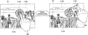
- a movement of the display object 113 C based on a successive chronological change in touch coordinates (trajectory of the drag operation) is conducted when the display object 113 C is able to move relatively along the trajectory of the drag operation.
- the dragging trajectory moves only a X component in the x direction or a Y component in the y direction.
- the display object 113 C moves in the same trajectory as the drag operation in a first half of an operation as depicted in the screen 9 d .
- the display object 113 C is not able to move in the y direction any more. Therefore, the display object 113 C moves in the x direction reflecting only the x component of the trajectory of the drag operation.
- the display object 113 C is moved based on the drag operation as displayed in a screen 9 f . That is, in a case in which an initial position of the display object 113 C displayed in a screen 9 e is the same as that displayed in the screen 9 c , the trajectory of the display object 113 C becomes the same as that displayed in the screen 9 d in FIG. 3 B , regardless of the initial position of the finger 20 f.
- FIG. 4 is a diagram illustrating an example of a functional configuration of a display device 10 according to the first embodiment.
- the display device 10 according to the first embodiment includes a touch detection part 11 , an operation determination part 12 , a first movement control part 13 , and a second movement control part 14 as functions for realizing movement patterns of the display object 113 C as illustrated in FIG. 3 A to FIG. 3 C .
- the touch detection part 11 detects a proximity or a contact of the indicator 20 with the image display LCD 113 and the touch panel 115 .
- the operation determination part 12 determines an input operation to the image display LCD 113 and the touch panel 115 based on a detection result of the touch detection part 11 .
- the operation determination part 12 determines whether the input operation is a tap operation or the drag operation.
- the first movement control part 13 and the second movement control part 14 control an operation of the display object 113 C on the image display LCD 113 based on an input operation.
- the operation determination part 12 determines the tap operation on the image display LCD 113 and the touch panel 115
- the first movement control part 13 moves the display object 113 C to the coordinates when coordinates of the tap operation are within the movable region 113 B, and the first movement control part 13 does not move the display object 113 C to the coordinates when the coordinates of the tap operation are outside the movable region 113 B.
- the second movement control part 14 moves the display object 113 C within the movable region 113 B based on a coordinate change of the drag operation within the detectable region 113 A.
- the functions of the touch detection part 11 , the operation determination part 12 , the first movement control part 13 , and the second movement control part 14 illustrated in FIG. 4 are realized by installing predetermined computer software (object movement program) on hardware such as a Large Scale Integration (LSI) realizing the LCD control device 112 and the touch panel control device 114 illustrated in FIG. 1 , and operating the image display LCD 113 and the touch panel 115 under control of the LCD control device 112 and the touch panel control device 114 .
- the LCD control device 112 and the touch panel control device 114 forming the display device 10 is able to be expressed as a computer device including a Central Processing Unit (CPU) as a processor, a Random Access Memory (RAM), and a Read Only Memory (ROM). That is, the object movement program according to the first embodiment is executed on the computer, so that the display device 10 functions as the touch detection part 11 , the operation determination part 12 , the first movement control part 13 , and the second movement control part 14 in FIG. 4 .
- CPU Central Processing Unit
- the touch detection part 11 is implemented by the touch panel 115 and the touch panel control device 114 illustrated in FIG. 1 .
- the operation determination part 12 is implemented by the touch panel control device 114 illustrated in FIG. 1 .
- the first movement control part 13 and the second movement control part 14 are implemented by the LCD control device 112 .
- FIG. 5 is a flowchart for explaining a movement control of the display object 113 C in response to the touch operation according to the first embodiment.
- step S 1 the touch detection part 11 (touch panel 115 ) detects whether or not the indicator 20 is in proximity or in contact with the image display LCD 113 , that is, whether or not the touch operation starts (detection step).
- the touch detection part 11 detects a state of a proximity or a contact with a predetermined sampling period, and calculates coordinates touched by the touch panel control device 114 every time.
- step S 1 NO
- the display object 113 C is displayed on the display coordinates at an end of a previous touch operation.
- the operation determination part 12 determines whether or not the touched coordinates are coordinates in the movable region 113 B of the display object 113 C (step S 2 ).
- step S 2 When touch start coordinates are coordinates in the movable region 113 B (step S 2 : YES), the display object 113 C is moved based on absolute coordinates, which are touched (step S 3 ).
- step S 5 When a touch operation is terminated without changing the coordinates by a certain amount or more from the start coordinates (almost not moving) (step S 5 : YES and step S 7 : YES), that is, when a tap operation is performed, the position designation of the display object 113 C is completed at the coordinates moved in step S 3 . That is, in a flow of step S 3 ⁇ step S 5 ⁇ step S 7 , the movement pattern from the screen 9 a to the screen 9 b in FIG. 3 A is obtained.
- step S 5 when there is a coordinate change of a certain amount or more from the touch start coordinates (step S 5 : NO), that is, when a drag operation is performed, the display object 113 C is moved relatively within the movable region 113 B from the coordinates moved in step S 3 based on the chronological change (trajectory) of the continuous touch coordinates (step S 6 ), and a position designation is completed at coordinates where the display object 113 C is displayed at an end of the touch operation (step S 8 : YES). That is, in a flow of step S 3 ⁇ step S 5 ⁇ step S 6 ⁇ step S 8 , a movement pattern is depicted on the screen 9 c to the screen 9 d in FIG. 3 B .
- step S 4 the display object 1130 is not moved from the coordinate before the touch operation is started.
- step S 5 the touch start coordinates (almost not moving)
- step S 7 the position designation of the display object 113 C is completed at the coordinates before the touch operation is started. That is, in a flow of step S 4 ⁇ step S 5 ⁇ step S 7 , the state displayed on the screen 9 e in FIG. 3 C is maintained after the touch operation is terminated.
- step S 5 when the coordinate change is conducted with a certain amount or more from the touch start coordinates (step S 5 : NO), that is, when the drag operation is performed, the display object 113 C is moved relatively within the movable region 113 B based on the continuous chronological change (trajectory) of the touch coordinates from the coordinates before the start of the touch operation (step S 6 ), and the position designation is completed at the coordinates where the display object 113 C is displayed at a time when the touch operation ends (step S 8 : YES). That is, in a flow of step S 4 ⁇ step S 5 ⁇ step S 6 ⁇ step S 8 , a movement pattern is represented on the screen 9 e to the screen 9 f in FIG. 3 C .
- a process of the operation determination part 12 and a process of the first movement control part 13 are conducted.
- the operation determination part 12 determines that the input operation on the image display LCD 113 is a tap operation, based on a detection result of the touch operation by the touch detection part 11 (the determination step).
- the first movement control part 13 moves the display object 113 C to tapped coordinates when the coordinates of the tap operation are within the movable region 113 B, and does not move the display object 113 C to tapped coordinates when the coordinates of the tap operation are within the movable region 113 B (first movement step).
- step S 3 determines that the input operation to the image display LCD 113 is determined to be a drag operation based on the detection result of the touch operation by the touch detection part 11 .
- the second movement control part 14 moves the display object 113 C within the movable region 113 B based on the coordinate change of the drag operation in the detectable region 113 A (second movement step).
- the display device 10 of the first embodiment when the display object 113 C is moved relatively by the drag operation, it is possible to use the detectable region 113 A, which is wider than the movable region 113 B, as a range for a touch operation, and it is also possible to restrict, within the movable region 113 B, a displaying of the display object 113 C.
- the above described movement control because the problem in the conventional configuration is eliminated, it is possible to improve the operability of the movement operation of the display object 113 C, and to consequently improve the operability of the touch operation of the user.
- FIG. 6 is a flowchart for explaining a movement control of the display object 113 C in response to a touch operation according to the second embodiment.
- the flowchart in FIG. 6 is basically the same as that in FIG. 5 , and each process of step S 21 to step S 28 in FIG. 6 is the same as each process of step S 1 to step S 8 in FIG. 5 .
- step S 21 YES and step S 22 : NO
- the subsequent operation is regarded as an invalid operation
- the display object 113 C is not changed (in the flow in FIG. 5 , the tap operation is an invalid operation; however, the drag operation moves the display object relatively).
- step S 24 after a continuous display (not moving) process is conducted to remain the display object 113 C at coordinates before the start of the touch operation, a process in the second embodiment ends at a time when the touch operation ends (step S 29 : YES) while the display object 113 C remains at the coordinates before a start of the touch operation.
- the second movement control part 14 also includes a function, which does not move the display object 113 C in a case in which start coordinates of the drag operation are outside the movable region 113 B.
- the first movement control part 13 (the LCD control device 112 ) does not move the display object to the coordinates
- the second movement control part 14 (the LCD control device 112 ) does not move the display object to the coordinates.
- a third embodiment will be described with reference to FIG. 7 to FIG. 9 .
- a display/non-display of the movable region 113 B is controlled.
- FIG. 7 A through FIG. 7 C are diagrams illustrating display examples of the movable region 113 B.
- FIG. 7 A is an example of a screen without displaying the movable region 113 B.
- FIG. 7 B and FIG. 7 C are examples of the screen with displaying the movable region 113 B.
- the display object 113 C (AF frame) is displayed regardless of whether the movable region 113 B is displayed.
- a transmission color is used so as not to hinder an overall confirmation of a subject image.
- FIG. 8 is a functional block diagram illustrating the display device 10 according to the third embodiment.
- the display/non-display of the movable region 113 B is controlled during the touch operation to satisfy such a requirement of the movable region 113 B as described above.
- the display device 10 in the third embodiment includes a touch detection part 11 , an operation determination part 12 , and a display control part 15 as functions for realizing the above described display process for the movable region 113 B, as illustrated in FIG. 8 .
- the display control part 15 displays the movable region 113 B when an input operation is performed outside the movable region 113 B. Meanwhile, according to the input operation performed in the movable region 113 B, it is controlled not to perform a display representing the movable region 113 B. More specifically, the display representing the movable region 113 B is performed when a drag operation is performed in the movable region 113 B, and the display representing the movable region 1133 is not performed when a tap operation is performed in the movable region 113 B. When there is no input operation, the display representing the movable region 113 B is not performed.
- the display control part 15 is implemented by the LCD control device 112 illustrated in FIG. 1 .
- FIG. 9 is a flowchart illustrating display control of the movable region 113 B according to the third embodiment.
- step S 31 before the touch detection part 11 detects a touch operation, that is, when there is no input operation, the display control part 15 (the LCD control device 112 ) controls the movable region 113 B not to be displayed (second non-display step).
- step S 32 YES
- step S 33 it is determined whether or not touched coordinates are in the movable region 113 B for the display object 113 C (step S 33 ).
- the movable region 113 B is displayed by the display control part 15 (step S 34 : display step).
- the display pattern of the movable region 113 B may be, for example, a boundary display depicted in FIG. 7 B or a filled display outside movable region 113 B depicted in FIG. 7 C .
- step S 33 when touching inside the movable region 113 B (step S 33 : YES), when the touch operation is terminated without a coordinate change of a certain amount or more from the touch start coordinates (step S 35 : YES and step S 37 : YES), in other words, when the tap operation is performed, the movable region 113 B remains not to be displayed (step S 39 : first non-display step), and this control flow is terminated.
- step S 35 When there is the coordinate change of a certain amount or more from the touch start coordinates (step S 35 : NO), that is, when a drag operation is performed, even in a case in which the touch start coordinates are inside or outside the movable region 113 B (both YES and NO in step S 33 ), the movable region 113 B is displayed during the drag operation (step S 36 ). At a time when the touch operation ends (step S 38 : YES), a mode is switched to a non-display mode in that the movable region 113 B is not displayed (step S 39 ) and this control flow is terminated.
- the display control is conducted such that the movable region 113 B is not displayed in a case of moving the display object 113 C by absolute coordinates due to the tap operation conducted in the movable region 113 B, and the movable region 113 B is displayed only in an operation where it is considered necessary to notify that the touch operation is conducted outside the movable region 113 B.
- the display control of the movable region 113 B in the third embodiment is used in combination with the movement control of the display object 113 C in accordance with a touch operation in the first embodiment and the second embodiment, so that the operability of the touch operation of the user is further improved.
- FIG. 10 is a flowchart for explaining a display control of the movable region 113 B according to the fourth embodiment.
- the flowchart of FIG. 10 is basically the same as the flowchart of FIG. 9 in the third embodiment, and the processes in step S 41 to step S 45 , step S 49 , and step S 51 in FIG. 10 are the same as the processes in step S 31 to step S 35 , step S 37 , and step S 39 in FIG. 9 .
- step S 46 when the touch coordinates are outside the movable region 113 B (step S 46 : NO), the display control part 15 displays the movable region 1133 (step S 48 ), and when the touch coordinates are within the movable region 113 B (step S 46 : YES), the display control part 15 does not display the movable region 113 B (step S 47 ).
- a mode is switched to a non-display mode in that the movable region 113 B is not displayed.
- this display control it is possible to display the movable region 113 B while restricting, with higher accuracy, to an operation, which requires a report of that the operation is conducted outside the movable region 113 B.
- FIG. 11 is a diagram illustrating an example of a functional configuration of a display device 10 according to the fifth embodiment.
- the user moves and manipulates the display object 113 C using the operation member 102 .
- display control of the movable region 113 B is different from the display control ( FIG. 7 and FIG. 8 ) at a time of the touch operation in the third embodiment and the fourth embodiment.
- the display device 10 according to a movement instruction of the display object 113 C entered by the operation member 102 , a display indicating a movable region 113 B is performed.
- the display device 10 includes an operation detection part 16 and a display control part 17 as functions for realizing the above described display process of the movable region 113 B, as illustrated in FIG. 10 .
- the operation detection part 16 detects a movement instruction of the display object 113 C entered by the operation member 102 .
- the operation member 102 is an operating member that is used for directional instructions such as, for example, a crosshair key or an 8-direction lever. These operating members may be provided with an ability to retain a direction of a movement (an operation of pressing and holding the crosshair key, an operation of turning and holding the 8-direction lever).
- the display control part 17 controls the display/non-display of the movable region 113 B based on the movement instruction detected by the operation detection part 16 .
- the operation detection part 16 and the display control part 17 are implemented by the LCD control device 112 illustrated in FIG. 1 .
- FIG. 12 is a flowchart for explaining the display control of the movable region 113 B in the fifth embodiment.
- the movable region 113 B is not displayed (non-display state) before an input of the movement operation is detected by the operation detection part 16 , because the display object 113 C is disposed in the movable region 113 B (step S 61 ).
- the movable region 113 B is displayed by the display control part 17 (step S 63 ).
- step S 64 While the movement operation is continuously conducted (NO in step S 64 ), when the movable region 113 B is continuously displayed, and then, the movement operation is completed (YES in step S 64 ), a mode is switched to a non-display mode in that the movable region 113 B is not displayed (step S 65 ), and this control flow ends.
- the movable region 113 B is displayed during an operation for retaining a movement direction instruction, and the movable region 113 B is not displayed in a case in which a movement instruction operation is not performed.
- a display of the movable region 113 B is restricted during the movement operation, it is possible to solve the problem in that the display becomes complicated and confirmation of a subject is hindered.
- FIG. 13 is a flowchart for explaining display control of the movable region 113 B according to the sixth embodiment.
- a display representing the movable region 113 B is performed in a case in which a position, at which the display object 113 C moves in accordance with a movement instruction entered by the operation member 102 , is a position adjacent to a boundary of the movable region 113 B.
- a display representing the movable region 113 B is performed in a case in which the display object 113 C is not in contact with a boundary of the movable region 113 B.
- step S 71 , step S 72 , step S 76 , and step S 77 in FIG. 13 are similar to those of step S 61 , step S 62 , step S 64 , and step S 65 in FIG. 12 .
- step S 72 when a start of the movement operation is detected by the operation detection part 16 (YES in step S 72 ), the display control part 17 determines in step S 73 whether or not the display object 113 C is in contact with a boundary portion of an outer edge of the movable region 113 B.
- the display control part 17 switches to a display mode for displaying the movable region 113 B (step S 74 ).
- step S 75 when the display object 113 C is not in contact with the boundary of the movable region 113 B (NO in step S 73 ), the movable region 113 B is not displayed by the display control part 17 (step S 75 ).
- the sixth embodiment it is possible to display the movable region 1133 by restricting to an operation, which is highly necessary to notify that the operation is about to go outside the movable region 113 B because the movable region 113 B is not displayed before the operation is conducted and the display object 113 C becomes in contact with the boundary of the movable region 113 B. Therefore, it is possible to solve the problem in that the display becomes complicated and confirmation of a subject is hindered in a case of always displaying the movable region 113 B.
- FIG. 14 is a flowchart for explaining display control of the movable region 113 B in the seventh embodiment.
- a display representing the movable region 113 B in accordance with the movement instruction is not performed.
- step S 81 , step S 82 , step S 86 , and step S 87 in FIG. 14 are similar to those of step S 71 , step S 72 , step S 76 , and step S 77 in FIG. 13 .
- step S 83 when a start of the movement operation is detected by the operation detection part 16 (YES in step S 82 ), the display control part 17 determines in step S 83 whether or not the display object 1130 can be moved to an instruction direction.
- the display control part 17 switches to a display mode for displaying the movable region 113 B (step S 85 ).
- step S 84 when the display object 113 C can be moved to the instruction direction by the display object 113 C even during the operation of holding the movement direction instruction (YES in step S 83 ), the movable region 113 B is retained by the display control part 17 so as not to be displayed (step S 84 ).
- the seventh embodiment it is possible to display the movable region 113 B by restricting to an operation, which is highly necessary to notify that the operation is about to go outside the movable region 113 B because the movable region 113 B is not displayed before the operation is conducted and the display object 113 C is unable to move to the instruction direction. Therefore, it is possible to solve the problem in that the display becomes complicated and confirmation of a subject is hindered in a case of always displaying the movable region 113 B.
- the seventh embodiment has been described with reference to the specific examples.
- the present disclosure is not limited to the first through seventh embodiments.
- the first through seventh embodiments to which design modifications have been made from time to time by those skilled in the art, are also encompassed by the present disclosure as long as they possess the features of the present disclosure.
- the elements provided in each of the first through seventh embodiments described above, and the arrangement, conditions, shape, and the like thereof, may be adapted and modified from time to time without being limited to those exemplified.
- Each element provided by each of the above described first through seventh embodiments may vary in combination as appropriate, unless there is a technical inconsistency.
- the present invention can be implemented in any convenient form, for example using dedicated hardware, or a mixture of dedicated hardware and software.
- the present invention may be implemented as computer software implemented by one or more networked processing apparatuses.
- the network can comprise any conventional terrestrial or wireless communications network, such as the Internet.
- the processing apparatuses can comprise any suitably programmed apparatuses such as a general purpose computer, personal digital assistant, mobile telephone (such as a WAP or 3G-compliant phone) and so on. Since the present invention can be implemented as software, each and every aspect of the present invention thus encompasses computer software implementable on a programmable device.
- the computer software can be provided to the programmable device using any storage medium for storing processor readable code such as a floppy disk, a hard disk, a CD ROM, a magnetic tape device or a solid state memory device.
- the hardware platform includes any desired kind of hardware resources including, for example, a processor such as a central processing unit (CPU), a random access memory (RAM), and a hard disk drive (HDD).
- the CPU may be implemented by any desired kind of any desired number of processors.
- the RAM may be implemented by any desired kind of volatile or non-volatile memory.
- the HDD may be implemented by any desired kind of non-volatile memory capable of storing a large amount of data.
- the hardware resources may additionally include an input device, an output device, or a network device, depending on the type of the apparatus. Alternatively, the HDD may be provided outside of the apparatus as long as the HDD is accessible.
- the CPU such as a cache memory of the CPU
- the RAM may function as a physical memory or a primary memory of the apparatus, while the HDD may function as a secondary memory of the apparatus.
Abstract
Description
Claims (8)
Applications Claiming Priority (6)
| Application Number | Priority Date | Filing Date | Title |
|---|---|---|---|
| JP2018-224201 | 2018-11-29 | ||
| JPJP2018-224201 | 2018-11-29 | ||
| JP2018-224202 | 2018-11-29 | ||
| JPJP2018-224202 | 2018-11-29 | ||
| JP2018224202A JP7172512B2 (en) | 2018-11-29 | 2018-11-29 | Display device, imaging device, display method, and display program |
| JP2018224201A JP7215117B2 (en) | 2018-11-29 | 2018-11-29 | Display device, imaging device, object moving method, and object moving program |
Publications (2)
| Publication Number | Publication Date |
|---|---|
| US20200177821A1 US20200177821A1 (en) | 2020-06-04 |
| US11523060B2 true US11523060B2 (en) | 2022-12-06 |
Family
ID=70849505
Family Applications (1)
| Application Number | Title | Priority Date | Filing Date |
|---|---|---|---|
| US16/697,926 Active 2040-09-06 US11523060B2 (en) | 2018-11-29 | 2019-11-27 | Display device, imaging device, object moving method, and recording medium |
Country Status (1)
| Country | Link |
|---|---|
| US (1) | US11523060B2 (en) |
Citations (14)
| Publication number | Priority date | Publication date | Assignee | Title |
|---|---|---|---|---|
| JP2001159730A (en) | 1999-12-02 | 2001-06-12 | Ricoh Co Ltd | Electronic camera |
| US20040165010A1 (en) * | 2003-02-25 | 2004-08-26 | Robertson George G. | System and method that facilitates computer desktop use via scaling of displayed bojects with shifts to the periphery |
| US20080002028A1 (en) * | 2006-06-30 | 2008-01-03 | Casio Computer Co., Ltd. | Imaging apparatus and computer readable recording medium |
| US20090003817A1 (en) * | 2007-06-28 | 2009-01-01 | Sony Corporation | Imaging apparatus, image display control method, and program |
| US20090244357A1 (en) * | 2008-03-27 | 2009-10-01 | Sony Corporation | Imaging apparatus, imaging method and program |
| US20120113056A1 (en) * | 2010-11-09 | 2012-05-10 | Sony Corporation | Input device, input method, and computer readable storage device |
| JP5373229B1 (en) | 2011-12-16 | 2013-12-18 | オリンパスイメージング株式会社 | IMAGING DEVICE, IMAGING METHOD THEREOF, AND STORAGE MEDIUM FOR STORING TRACKING PROGRAM PROCESSABLE BY COMPUTER |
| US20150193110A1 (en) | 2014-01-06 | 2015-07-09 | Konica Minolta, Inc. | Object stop position control method, operation display device and non-transitory computer-readable recording medium |
| US20150304547A1 (en) * | 2013-01-04 | 2015-10-22 | Fujifilm Corporation | Image processing device, imaging device, image processing method and computer readable medium |
| US20160165142A1 (en) * | 2014-12-08 | 2016-06-09 | Canon Kabushiki Kaisha | Image capturing apparatus, control method therefor, and storage medium |
| JP2018082747A (en) | 2016-11-21 | 2018-05-31 | 株式会社コーエーテクモゲームス | Game program, recording medium, and game processing method |
| US20180205874A1 (en) * | 2017-01-16 | 2018-07-19 | Canon Kabushiki Kaisha | Image capturing control apparatus, control method, and storage medium |
| US20190199934A1 (en) * | 2017-12-22 | 2019-06-27 | Canon Kabushiki Kaisha | Electronic device, control method for controlling the same, and storage medium |
| US20200021748A1 (en) * | 2018-07-13 | 2020-01-16 | Canon Kabushiki Kaisha | Image sensing apparatus and control method of image sensing apparatus |
-
2019
- 2019-11-27 US US16/697,926 patent/US11523060B2/en active Active
Patent Citations (18)
| Publication number | Priority date | Publication date | Assignee | Title |
|---|---|---|---|---|
| JP2001159730A (en) | 1999-12-02 | 2001-06-12 | Ricoh Co Ltd | Electronic camera |
| US20040165010A1 (en) * | 2003-02-25 | 2004-08-26 | Robertson George G. | System and method that facilitates computer desktop use via scaling of displayed bojects with shifts to the periphery |
| US20080002028A1 (en) * | 2006-06-30 | 2008-01-03 | Casio Computer Co., Ltd. | Imaging apparatus and computer readable recording medium |
| US20090003817A1 (en) * | 2007-06-28 | 2009-01-01 | Sony Corporation | Imaging apparatus, image display control method, and program |
| JP2009008954A (en) | 2007-06-28 | 2009-01-15 | Sony Corp | Imaging device, image display control method and program |
| US20090244357A1 (en) * | 2008-03-27 | 2009-10-01 | Sony Corporation | Imaging apparatus, imaging method and program |
| US20120113056A1 (en) * | 2010-11-09 | 2012-05-10 | Sony Corporation | Input device, input method, and computer readable storage device |
| US9113073B2 (en) | 2011-12-16 | 2015-08-18 | Olympus Imaging Corp. | Imaging apparatus and imaging method of the same, and storage medium to store computer-processible tracking program |
| JP5373229B1 (en) | 2011-12-16 | 2013-12-18 | オリンパスイメージング株式会社 | IMAGING DEVICE, IMAGING METHOD THEREOF, AND STORAGE MEDIUM FOR STORING TRACKING PROGRAM PROCESSABLE BY COMPUTER |
| US20150304547A1 (en) * | 2013-01-04 | 2015-10-22 | Fujifilm Corporation | Image processing device, imaging device, image processing method and computer readable medium |
| US20150193110A1 (en) | 2014-01-06 | 2015-07-09 | Konica Minolta, Inc. | Object stop position control method, operation display device and non-transitory computer-readable recording medium |
| JP2015130016A (en) | 2014-01-06 | 2015-07-16 | コニカミノルタ株式会社 | Method of controlling stop position of object, operation display device, and program |
| US20160165142A1 (en) * | 2014-12-08 | 2016-06-09 | Canon Kabushiki Kaisha | Image capturing apparatus, control method therefor, and storage medium |
| JP2018082747A (en) | 2016-11-21 | 2018-05-31 | 株式会社コーエーテクモゲームス | Game program, recording medium, and game processing method |
| US20180205874A1 (en) * | 2017-01-16 | 2018-07-19 | Canon Kabushiki Kaisha | Image capturing control apparatus, control method, and storage medium |
| JP2018117186A (en) | 2017-01-16 | 2018-07-26 | キヤノン株式会社 | Imaging control device, imaging device, control method, program, and storage medium |
| US20190199934A1 (en) * | 2017-12-22 | 2019-06-27 | Canon Kabushiki Kaisha | Electronic device, control method for controlling the same, and storage medium |
| US20200021748A1 (en) * | 2018-07-13 | 2020-01-16 | Canon Kabushiki Kaisha | Image sensing apparatus and control method of image sensing apparatus |
Non-Patent Citations (1)
| Title |
|---|
| Japanese Office Action for 2018-224201 dated Jun. 28, 2022. |
Also Published As
| Publication number | Publication date |
|---|---|
| US20200177821A1 (en) | 2020-06-04 |
Similar Documents
| Publication | Publication Date | Title |
|---|---|---|
| JP5620947B2 (en) | Electronic device, control method therefor, program, and storage medium | |
| JP6103807B2 (en) | Display control apparatus, control method thereof, and program | |
| US20050248542A1 (en) | Input device and method for controlling input device | |
| JP5893456B2 (en) | Display control apparatus, control method therefor, program, and storage medium | |
| US9544556B2 (en) | Projection control apparatus and projection control method | |
| JP5924554B2 (en) | Object stop position control method, operation display device, and program | |
| US6992661B2 (en) | Electronic device, digital still camera and display control method | |
| JP2003345491A (en) | Display input apparatus, display input method, program and recording medium | |
| CN112584043B (en) | Auxiliary focusing method and device, electronic equipment and storage medium | |
| US20160196032A1 (en) | Information processing apparatus, information processing method and a non-transitory storage medium | |
| JPWO2014030290A1 (en) | Electronic device, device operating method and program | |
| JP5220157B2 (en) | Information processing apparatus, control method therefor, program, and storage medium | |
| CN110661946B (en) | Electronic device, control method of electronic device, and computer-readable medium | |
| JP4879933B2 (en) | Screen display device, screen display method and program | |
| US20140253479A1 (en) | Display device and display method | |
| US11523060B2 (en) | Display device, imaging device, object moving method, and recording medium | |
| JP6104338B2 (en) | Electronic device, control method therefor, program, and storage medium | |
| JP2011034512A (en) | Display controller and display control method | |
| US11009991B2 (en) | Display control apparatus and control method for the display control apparatus | |
| JP7172512B2 (en) | Display device, imaging device, display method, and display program | |
| JP7215117B2 (en) | Display device, imaging device, object moving method, and object moving program | |
| JP6525753B2 (en) | Display control device, control method thereof, and program | |
| JP7091159B2 (en) | Electronic devices and their control methods | |
| CN110543274B (en) | Image display method, mobile terminal and device with storage function | |
| JP6239077B2 (en) | Electronic device, control method therefor, program, and storage medium |
Legal Events
| Date | Code | Title | Description |
|---|---|---|---|
| FEPP | Fee payment procedure |
Free format text: ENTITY STATUS SET TO UNDISCOUNTED (ORIGINAL EVENT CODE: BIG.); ENTITY STATUS OF PATENT OWNER: LARGE ENTITY |
|
| STPP | Information on status: patent application and granting procedure in general |
Free format text: DOCKETED NEW CASE - READY FOR EXAMINATION |
|
| STPP | Information on status: patent application and granting procedure in general |
Free format text: NON FINAL ACTION MAILED |
|
| STPP | Information on status: patent application and granting procedure in general |
Free format text: RESPONSE TO NON-FINAL OFFICE ACTION ENTERED AND FORWARDED TO EXAMINER |
|
| STPP | Information on status: patent application and granting procedure in general |
Free format text: AWAITING TC RESP., ISSUE FEE NOT PAID |
|
| STPP | Information on status: patent application and granting procedure in general |
Free format text: DOCKETED NEW CASE - READY FOR EXAMINATION |
|
| STPP | Information on status: patent application and granting procedure in general |
Free format text: NOTICE OF ALLOWANCE MAILED -- APPLICATION RECEIVED IN OFFICE OF PUBLICATIONS |
|
| STPP | Information on status: patent application and granting procedure in general |
Free format text: PUBLICATIONS -- ISSUE FEE PAYMENT VERIFIED |
|
| STCF | Information on status: patent grant |
Free format text: PATENTED CASE |