US11522326B2 - Whirlpool bath controller with intelligent load control to reduce power requirements - Google Patents
Whirlpool bath controller with intelligent load control to reduce power requirements Download PDFInfo
- Publication number
- US11522326B2 US11522326B2 US16/776,435 US202016776435A US11522326B2 US 11522326 B2 US11522326 B2 US 11522326B2 US 202016776435 A US202016776435 A US 202016776435A US 11522326 B2 US11522326 B2 US 11522326B2
- Authority
- US
- United States
- Prior art keywords
- high voltage
- control system
- pump
- power
- electronic controller
- Prior art date
- Legal status (The legal status is an assumption and is not a legal conclusion. Google has not performed a legal analysis and makes no representation as to the accuracy of the status listed.)
- Active, expires
Links
Images


Classifications
-
- H—ELECTRICITY
- H01—ELECTRIC ELEMENTS
- H01R—ELECTRICALLY-CONDUCTIVE CONNECTIONS; STRUCTURAL ASSOCIATIONS OF A PLURALITY OF MUTUALLY-INSULATED ELECTRICAL CONNECTING ELEMENTS; COUPLING DEVICES; CURRENT COLLECTORS
- H01R25/00—Coupling parts adapted for simultaneous co-operation with two or more identical counterparts, e.g. for distributing energy to two or more circuits
- H01R25/006—Coupling parts adapted for simultaneous co-operation with two or more identical counterparts, e.g. for distributing energy to two or more circuits the coupling part being secured to apparatus or structure, e.g. duplex wall receptacle
-
- A—HUMAN NECESSITIES
- A47—FURNITURE; DOMESTIC ARTICLES OR APPLIANCES; COFFEE MILLS; SPICE MILLS; SUCTION CLEANERS IN GENERAL
- A47K—SANITARY EQUIPMENT; ACCESSORIES THEREFOR, e.g. TOILET ACCESSORIES
- A47K3/00—Baths; Showers; Appurtenances therefor
- A47K3/10—Wave-producers or the like
-
- A—HUMAN NECESSITIES
- A61—MEDICAL OR VETERINARY SCIENCE; HYGIENE
- A61H—PHYSICAL THERAPY APPARATUS, e.g. DEVICES FOR LOCATING OR STIMULATING REFLEX POINTS IN THE BODY; ARTIFICIAL RESPIRATION; MASSAGE; BATHING DEVICES FOR SPECIAL THERAPEUTIC OR HYGIENIC PURPOSES OR SPECIFIC PARTS OF THE BODY
- A61H33/00—Bathing devices for special therapeutic or hygienic purposes
- A61H33/005—Electrical circuits therefor
-
- A—HUMAN NECESSITIES
- A61—MEDICAL OR VETERINARY SCIENCE; HYGIENE
- A61H—PHYSICAL THERAPY APPARATUS, e.g. DEVICES FOR LOCATING OR STIMULATING REFLEX POINTS IN THE BODY; ARTIFICIAL RESPIRATION; MASSAGE; BATHING DEVICES FOR SPECIAL THERAPEUTIC OR HYGIENIC PURPOSES OR SPECIFIC PARTS OF THE BODY
- A61H33/00—Bathing devices for special therapeutic or hygienic purposes
- A61H33/0087—Therapeutic baths with agitated or circulated water
-
- A—HUMAN NECESSITIES
- A61—MEDICAL OR VETERINARY SCIENCE; HYGIENE
- A61H—PHYSICAL THERAPY APPARATUS, e.g. DEVICES FOR LOCATING OR STIMULATING REFLEX POINTS IN THE BODY; ARTIFICIAL RESPIRATION; MASSAGE; BATHING DEVICES FOR SPECIAL THERAPEUTIC OR HYGIENIC PURPOSES OR SPECIFIC PARTS OF THE BODY
- A61H33/00—Bathing devices for special therapeutic or hygienic purposes
- A61H33/0095—Arrangements for varying the temperature of the liquid
-
- A—HUMAN NECESSITIES
- A61—MEDICAL OR VETERINARY SCIENCE; HYGIENE
- A61H—PHYSICAL THERAPY APPARATUS, e.g. DEVICES FOR LOCATING OR STIMULATING REFLEX POINTS IN THE BODY; ARTIFICIAL RESPIRATION; MASSAGE; BATHING DEVICES FOR SPECIAL THERAPEUTIC OR HYGIENIC PURPOSES OR SPECIFIC PARTS OF THE BODY
- A61H33/00—Bathing devices for special therapeutic or hygienic purposes
- A61H33/60—Components specifically designed for the therapeutic baths of groups A61H33/00
- A61H33/601—Inlet to the bath
- A61H33/6021—Nozzles
- A61H33/6026—Nozzles in the bathtub connected to an outside pump circuit without modification of the walls
-
- A—HUMAN NECESSITIES
- A61—MEDICAL OR VETERINARY SCIENCE; HYGIENE
- A61H—PHYSICAL THERAPY APPARATUS, e.g. DEVICES FOR LOCATING OR STIMULATING REFLEX POINTS IN THE BODY; ARTIFICIAL RESPIRATION; MASSAGE; BATHING DEVICES FOR SPECIAL THERAPEUTIC OR HYGIENIC PURPOSES OR SPECIFIC PARTS OF THE BODY
- A61H33/00—Bathing devices for special therapeutic or hygienic purposes
- A61H33/60—Components specifically designed for the therapeutic baths of groups A61H33/00
- A61H33/6068—Outlet from the bath
- A61H33/6073—Intake mouths for recirculation of fluid in whirlpool baths
-
- H—ELECTRICITY
- H02—GENERATION; CONVERSION OR DISTRIBUTION OF ELECTRIC POWER
- H02J—ELECTRIC POWER NETWORKS; CIRCUIT ARRANGEMENTS OR SYSTEMS FOR SUPPLYING OR DISTRIBUTING ELECTRIC POWER; SYSTEMS FOR STORING ELECTRIC ENERGY
- H02J3/00—Circuit arrangements for AC mains or AC distribution networks
-
- H—ELECTRICITY
- H05—ELECTRIC TECHNIQUES NOT OTHERWISE PROVIDED FOR
- H05K—PRINTED CIRCUITS; CASINGS OR CONSTRUCTIONAL DETAILS OF ELECTRIC APPARATUS; MANUFACTURE OF ASSEMBLAGES OF ELECTRICAL COMPONENTS
- H05K5/00—Casings, cabinets or drawers for electric apparatus
- H05K5/0017—Casings, cabinets or drawers for electric apparatus with operator interface units
-
- A—HUMAN NECESSITIES
- A61—MEDICAL OR VETERINARY SCIENCE; HYGIENE
- A61H—PHYSICAL THERAPY APPARATUS, e.g. DEVICES FOR LOCATING OR STIMULATING REFLEX POINTS IN THE BODY; ARTIFICIAL RESPIRATION; MASSAGE; BATHING DEVICES FOR SPECIAL THERAPEUTIC OR HYGIENIC PURPOSES OR SPECIFIC PARTS OF THE BODY
- A61H33/00—Bathing devices for special therapeutic or hygienic purposes
- A61H33/005—Electrical circuits therefor
- A61H2033/0058—Electrical circuits therefor controlled by the user
- A61H2033/0062—Electrical circuits therefor controlled by the user with electro-pneumatic or -hydraulic switches
-
- A—HUMAN NECESSITIES
- A61—MEDICAL OR VETERINARY SCIENCE; HYGIENE
- A61H—PHYSICAL THERAPY APPARATUS, e.g. DEVICES FOR LOCATING OR STIMULATING REFLEX POINTS IN THE BODY; ARTIFICIAL RESPIRATION; MASSAGE; BATHING DEVICES FOR SPECIAL THERAPEUTIC OR HYGIENIC PURPOSES OR SPECIFIC PARTS OF THE BODY
- A61H33/00—Bathing devices for special therapeutic or hygienic purposes
- A61H33/005—Electrical circuits therefor
- A61H2033/0058—Electrical circuits therefor controlled by the user
- A61H2033/0079—Electrical circuits therefor controlled by the user using remote control signal transmission devices, e.g. ultrasonic, infrared
-
- A—HUMAN NECESSITIES
- A61—MEDICAL OR VETERINARY SCIENCE; HYGIENE
- A61H—PHYSICAL THERAPY APPARATUS, e.g. DEVICES FOR LOCATING OR STIMULATING REFLEX POINTS IN THE BODY; ARTIFICIAL RESPIRATION; MASSAGE; BATHING DEVICES FOR SPECIAL THERAPEUTIC OR HYGIENIC PURPOSES OR SPECIFIC PARTS OF THE BODY
- A61H2201/00—Characteristics of apparatus not provided for in the preceding codes
- A61H2201/02—Characteristics of apparatus not provided for in the preceding codes heated or cooled
- A61H2201/0207—Characteristics of apparatus not provided for in the preceding codes heated or cooled heated
-
- A—HUMAN NECESSITIES
- A61—MEDICAL OR VETERINARY SCIENCE; HYGIENE
- A61H—PHYSICAL THERAPY APPARATUS, e.g. DEVICES FOR LOCATING OR STIMULATING REFLEX POINTS IN THE BODY; ARTIFICIAL RESPIRATION; MASSAGE; BATHING DEVICES FOR SPECIAL THERAPEUTIC OR HYGIENIC PURPOSES OR SPECIFIC PARTS OF THE BODY
- A61H2201/00—Characteristics of apparatus not provided for in the preceding codes
- A61H2201/50—Control means thereof
- A61H2201/5097—Control means thereof wireless
Definitions
- Whirlpool bath installations typically include high power loads such as a heater for heating the bath water, a pump for pumping water through a recirculating water flow path, a blower for air bubble features, and may include a drain pump to quickly drain water from the tub.
- Low voltage loads may include lighting and valve controls.
- the multiple loads have in the past required separate 15 or 20 A circuits be installed for multiple high power loads to the room in which the whirlpool bath is to be installed.
- the pump(s) and heater typically require separate circuit outlets each on a separate breaker to support the electrical power demands of the installation.
- FIG. 1 is a diagrammatic illustration of a whirlpool bath installation.
- FIG. 2 is a schematic diagram illustrating an exemplary embodiment of a controller for a whirlpool bath in accordance with aspects of the invention.
- FIG. 3 illustrates an exemplary embodiment of a controller housing with a cover.
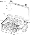
- FIG. 3 A illustrates an alternate embodiment of a controller housing with a cover.
- FIG. 4 is a table illustrating load control sequences in response to user input via an electronic control panel.
- FIG. 5 is a table illustrating load control in response to user input via air button actuations.
- FIG. 1 diagrammatically illustrates an exemplary whirlpool bath installation which employs a controller to control operation of the system devices.
- the installation in this example is a walk-in tub installation, which includes a tub structure 10 which includes a water reservoir defined by the tub structure, and a door 14 which swings on hinges from a water-tight closed position (shown in FIG. 1 ), and an open position which allows the user ready egress into and from the water reservoir.
- the tub structure 10 defines a seat platform 16 for the user to sit while bathing with the door closed, and water filling the reservoir to a comfortable level for the user.
- Valve elements allow the user to control the filling of the bathing water into the tub reservoir.
- the tub structure 10 defines an open space 20 under and behind the seat 16 , into which the tub installation pumps, controller, various other equipment and water pipes may be installed.
- the installation equipment may be mounted within the space 20 , e.g. to a platform 22 .
- a user interface control panel 42 may be positioned for ready access by the user, to control operation of the tub functions.
- the tub installation includes a network of water jets through which water is pumped by the whirlpool pump under pressure to provide a therapeutic effect for the user.
- a recirculating water flow path is provided, with the pump drawing bathing water from the reservoir through a suction fitting (not shown), and direct pressurized water from the pump to the water jets.
- Another function which may be implemented in an exemplary embodiment is a rapid water discharge function, activated by the user once finished bathing, to actively pump water out from the reservoir into the drain, to speed up the tub drain process so that the user when finished bathing, may open the door 14 without water escaping through the door opening.
- a drain pump may implement this function.
- the installation may include high voltage loads as diagrammatically depicted in FIG. 1 , including a whirlpool pump 30 to pump water through a recirculating water flow path including jets, a water heater 36 in the water flow path for heating the water, a blower 34 for blowing air through air jets or an air channel, and a drain pump 32 to quickly drain water from the whirlpool tub.
- a heat pad 38 to warm the tub in the area of the user's shoulders, for example. Some of these loads may be omitted from the system, depending on the installation.
- the high voltage loads typically include power cables and line voltage sockets, such as illustrated in FIG. 1 as power cords and sockets 30 A for pump 30 and 32 A for the drain pump 32 . In a conventional installation, each of the power connectors for the high voltage loads would be connected to individual line voltage sockets installed near the tub installation, typically on a wall.
- the installation may also include low voltage loads, such as lights 40 , and electrically controlled valves 44 A and 44 B to control the flow of water through different paths or to different devices.
- low voltage loads such as lights 40
- electrically controlled valves 44 A and 44 B to control the flow of water through different paths or to different devices.
- FIG. 2 is a schematic diagram of an exemplary embodiment of a control system 50 for a whirlpool bath installation.
- the exemplary embodiment of the control system 50 includes a single high voltage input power plug connector 52 , in this example a 120V AC connector for 20 A service.
- the connector 52 will be connected to a line voltage service connector located near the tub installation, e.g. on an adjacent wall.
- the system also includes a controller 60 , which in an exemplary embodiment includes a microprocessor, microcomputer, a gate array or other logic circuitry programmed or programmable to perform the functions described below.
- the system 50 does not include, and is free of, over-limit power protections for the bathing installation or its devices.
- over-limit power protections is meant that the system relies on the circuit breaker on the line voltage service circuit to which the plug connector 52 for the system is connected; no circuit breakers or fuses are incorporated in the circuitry of the system 50 to provide current or voltage protection.
- Each of the high power loads (pumps, blower, whirlpool heater, heat pad) that plug into the sockets on the system 50 are to be agency approved (such as Underwriters Laboratories (UL)) and as such will have their own agency required certification protection in place.
- UL Underwriters Laboratories
- the only current protection is provided by a circuit breaker on the input power service to which the power connector 52 is connected.
- the control system 50 is configured to distribute electrical power to a plurality of high voltage loads, which if actuated simultaneously would exceed the available current draw through the input power service. In an exemplary embodiment, the control system 50 performs this by managing the on/off status of the high power loads, as well as the low voltage loads, so that the available current is not exceeded.
- the system 50 includes a plurality of connector sockets 80 , 82 , 84 , 86 and 88 in this example, which are available for plug-in of the power cords for the high voltage loads.
- the sockets are NEMA receptacles, mounted to the housing of the system, making it convenient to connect the power cords of the loads during installation.
- AC power is connected through respective switches 72 , 74 , 76 , 78 and 79 to the corresponding connector sockets.
- the switches may be relays, triacs, SCRs or other devices, and are controlled by outputs of the controller 60 .
- socket 80 is assigned to the whirlpool pump for pumping water through the bath jets, and which nominally draws 8 Amps.
- An ozone generator can also be powered through the socket 80 , either by use of a piggyback plug or by plugging the ozone generator electrical power cord into an auxiliary outlet on the whirlpool pump, as described in U.S. Pat. No. 8,866,336, the entire contents of which are incorporated herein by this reference.
- Socket 82 is assigned to the drain pump for rapid discharge of the water from the bath tub, and which nominally draws 5.5 Amps.
- Socket 84 is assigned to the air blower for blowing air through the tub jets, and nominally draws 8 Amps.
- Socket 86 is assigned to the system heater for heating water in the recirculating water flow path, and which nominally draws 10.5 Amp. These nominal current draws are the rated current draws, and are exemplary only. All loads cannot be powered on simultaneously without the rated current draw exceeding the available current capacity (20 Amps) and tripping a circuit breaker. Typically for conventional installations, separate services, each with an associated power socket, would be required to service the high voltage loads.
- switch 76 controlling current drive to the socket 84 associated with a blower, is a triac to allow the controller 60 to modulate the current drive to the blower, e.g. to allow current levels of 40%, 50%, 60%, 70%, 80%, 90% and 100%, as well as off (0%).
- the controller 60 is configured to energize socket 84 at 100% current for two minutes as a purge cycle, after twenty minutes has elapsed from the last command to the controller 60 .
- the bath installation may also include low voltage loads, such as lights, an ozone generator, a heat pad attached to the outside of the bath tub to warm an area of the tub before the tub fills with warm water, and valves for controlling the water flow through the plumbing of the installation.
- the system 50 includes a transformer 70 connected to the input AC power to transform into 12 VDC for powering the low voltage loads, and 5 VDC for powering the controller 60 .
- the 12 VDC power is connected through switches 90 , 92 and 94 to the low power loads, in this example lights and actuators for valves V 1 and V 2 .
- Outputs of the controller 60 determine the status of the switches to selectively apply power to the low voltage loads.
- Indicator lights 112 - 1 , 112 - 2 , 112 - 3 , 112 - 4 and 112 - 5 may be provided to visually indicate the energization status of the high power sockets 80 , 82 , 84 , 86 , 88 .
- indicator lights 114 - 1 , 114 - 2 and 114 - 3 may be included to indicate the energization status of the low voltage lines 90 A, 92 A and 94 A.
- An indicator light 112 - 6 may be provided to indicate when the control system 50 is plugged into a wall outlet and the wall outlet has power.
- the control system preferably includes a housing 56 for mounting the electronic controller, the transformer, the switches and the output high voltage and low voltage connections.
- FIG. 3 illustrates an exemplary embodiment of a housing 56 with a cover 58 .
- An interior working panel 55 is mounted inside the housing 56 .
- the high voltage output sockets 80 , 82 , 84 , 86 and 88 are positioned on the panel 55 within the housing so that corresponding wiring connectors for the respective loads can be electrically connected to the high voltage sockets, e.g. inserted into, instead of to respective separate high voltage service sockets on separate service circuits.
- the housing 56 includes a side port 56 A for the single input electrical power connection 52 .
- the housing 56 also mounts on side 56 B the air switch receptacles 100 - 2 F, 100 - 2 G, 100 - 2 H, 100 - 21 and 100 - 2 J.
- the cover 58 includes a dome 58 A over the high voltage sockets to provide clearance for the load device connectors plugged into the sockets
- Power and low voltage cord strain relief is provided by scalloped regions underlaying bracket 56 B 1 which are formed in edge 56 C of the housing 56 .
- the power and low voltage wires are passed under the bracket, which is held in place by screw fasteners (not shown).
- FIG. 3 shows dummy wires held in place by the bracket 59 .
- Scalloped regions 58 B are formed in the edge 58 C of the cover 58 and compress the cords.
- the housing 56 and cover 58 may be injection molded from a plastic material.
- An elastomeric gasket 56 D is fitted to a groove in the edge 56 C for sealing the cover to the housing.
- FIG. 3 A illustrates an alternate embodiment of a control system 50 ′ with a housing structure 56 ′.
- the high voltage connector sockets 80 , 82 , 84 , 86 , 88 are mounted in a boss structure 57 , and are oriented in a plane transverse to the panel surface 55 ′.
- the power cords connected to the sockets may be directed out along the panel to the edge of the housing under bracket 56 B 1 ′, so that the dome 58 A′ in the cover 58 ′ may be reduced in height, in comparison to the dome 58 A in the embodiment of FIG. 3 .
- the power cords may be engaged by strain relief as in the embodiment of FIG. 3 .
- the boss could orient the plug sockets to an angle other than 90 degrees relative to the panel surface 55 ′, such as 45 degrees.
- the control system 50 may receive user commands to control the bathing installation operation.
- the system control inputs may be provided in one or more of several ways, through a control panel input system 100 - 1 , through a set 100 - 2 of air buttons, by Wifi signals received through WiFi module 100 - 3 which may optional be connect to data bus 100 - 1 B, or by wireless signals from a hand-held remote control which communicate with wireless module 100 - 4 in communication with controller 60 .
- the system 50 may include one control input system or any combination of the control input systems.
- the control panel system includes control panel 100 - 1 A with a set of buttons 100 - 1 C- 100 - 1 G which may be activated by the user.
- the panel is connected to the controller 60 by a DC data bus 100 - 1 B.
- the air button set 100 - 2 includes receptacles 100 - 2 F- 100 - 2 J ( FIG. 2 ) for connection to air tubes from the respective air buttons 100 - 2 A- 100 - 2 E mounted on a surface such as a surface of the tub, for example.
- the receptacles are connected by air lines to the respective air switches 100 - 2 K- 100 - 2 N, whose outputs are electrical switch status signals connected to inputs of the controller 60 .
- the control system 50 further optionally includes a wireless module 100 - 4 ( FIG. 2 ) connected to the controller 60 , which is responsive to wireless (e.g. RF, infrared or BluetoothTM) signals from a remote control 100 - 5 .
- the remote control device may be a hand-held device.
- the module 100 - 4 could also be a Bluetooth module connected to a user's smart phone or tablet running an application program for the system.
- the control system further optionally includes a WiFi module 100 - 3 connected to the data buss 100 - 1 B, which is configured to receive control signals from a WiFi network.
- the controller 60 implements a control sequence responsive to the user inputs which manages the power distribution to avoid exceeding the available current through the single AC input 52 .
- FIG. 4 is a table illustrating the operation of the control system 50 in response to user input from the electronic control panel 100 - 1 .
- the operation is controlled by rules governing the activation states of the various loads.
- the rules may be implemented by programming an algorithm in a microprocessor or microcomputer, for example. Alternatively, the rules may be implemented by hard-wired gate arrays.
- This exemplary embodiment has a load configuration of a heat pad, a jets (whirlpool) pump, a blower pump, lights, a drain pump and a water heater.
- the left-most column “Button Pressed” with buttons 1 . . . 5 correlates to buttons 100 - 1 C . . . 100 - 1 G in FIG. 2 .
- socket 88 associated with the heat pad is energized, with a 35-minute time out, which is independent of all other timers.
- a second button push will turn off socket 88 for the heat pad.
- a typical heat pad may operate at 115 VAC with a current rating of 1 Amp, or alternatively at 24 V DC with a nominal current draw of 4 A, powered through a transformer connected to socket 88 .
- the second button 100 - 1 D in input system 100 - 1 is assigned to control the jets (whirlpool) pump associated with socket 80 .
- the first button push energizes sockets 80 and 86 to turn on the pump and also the heater (assigned to socket 86 ) for a 20 minute timeout period.
- the drain pump (socket 82 ) as well as low voltage outputs 92 A, 94 A are turned off. So at this state, the high voltage loads (whirlpool pump and heater) nominally draw 18 . 5 A, less than the 20 A service.
- a second button de-energizes sockets 80 and 86 to turn off the whirlpool pump and the heater.
- the third button 100 - 1 E in input system 100 - 1 is assigned to control the blower (socket 84 ).
- a first button push energizes socket 84 to turn on the blower and de-energizes socket 86 to turn off the heater.
- the drive current to the blower is modulated through a scroll process, from 40% and increasing by increments of 10%, then repeating from 40%. With the blower and pump on at 100%, the high voltage loads draw 167 A in an exemplary embodiment.
- a further button push after the first or after a press and hold de-energizes socket 86 to turn off the blower.
- the fourth button 100 - 1 F in input system 100 - 1 is assigned to control switch 90 and the low voltage output, in this case assigned to a light or lights.
- the first button push turns the light on, with a 20 minute timeout; a second button push turns the light off.
- the timeout is independent of all other timers.
- the fifth button 100 - 1 G in input system 100 - 1 is assigned to the drain pump (socket 82 ).
- a first button push energizes socket 82 to turn on the drain pump for a 3 minute timeout, and de-energizes sockets 80 , 84 , 86 and low voltage outputs 92 A, 94 A to ensure that the blower, the heater, pump and low voltage loads are all turned off.
- the controller 60 ensures that sockets 80 and 84 for the whirlpool pump and the blower cannot be energized when socket 84 for the drain pump is energized.
- a second button push de-energizes socket 84 to turn the drain pump off.
- FIG. 5 illustrates an exemplary embodiment of the programmed states of the loads in response to air switch presses using the input system 100 - 2 ( FIG. 2 ).
- sockets 80 and 86 for the whirlpool pump (socket 80 ) and the heater (socket 86 ) are energized for a timeout period (20 minutes in this example), with socket 82 for the drain pump and the low voltage outputs ( 92 A, 94 A) are de-energized.
- Air switch 2 ( 100 - 2 B) controls socket 84 for the blower.
- First, second and third button pushes and releases will energize the socket 84 at 40%, 70% and 100% of maximum current draw, respectively, in this embodiment.
- a fourth button push and release will de-energize socket 84 to turn the blower off.
- the controller 60 is configured to energize socket 84 at 100% current draw for a purge cycle twenty minutes after the last command to the controller from the input system.
- the lights powered by low voltage output 90 A are controlled by air switch 3 ( 100 - 2 C).
- a first button push turns the lights on for a 20 minute timeout; a second button push turns the lights off. The operation of lights is independent of all other timers.
- the fourth button ( 100 - 2 D) controls the drain pump (socket 82 ).
- a first button push turns the drain pump on for a 3 minute timeout, and the whirlpool pump, heater, blower and low voltage outputs 92 A and 94 A off.
- a second button push within the timeout turns the drain pump off.
- Air switch 5 ( 100 - 2 E) in this exemplary embodiment controls the low voltage output 92 A, which may drive a valve for directing water flow in the recirculating water flow path.
- the controller 60 is programmed to only turn the valve on (open) in response to a first button push if the whirlpool pump is on; a second button push turns the valve off (closed).
- the low voltage outlet 92 A will time out with the whirlpool pump.
- the controller may be programmed with different time intervals or control sequences.
- air switch 100 - 2 E might be programmed to turn outlet 88 on/off for a heat pad.
- different load devices may be employed.
- the load device 32 may be a micro-bubble pump instead of a drain pump, and the plumbing adapted to support the micro-bubble pump. Such a pump forces water under pressure with a small amount of entrained air to create milky appearance.
- the programming would be the same, except the timer is changed to twenty minutes instead of three minutes ( FIGS. 4 , 5 ) in one example.
Landscapes
- Health & Medical Sciences (AREA)
- Public Health (AREA)
- Epidemiology (AREA)
- General Health & Medical Sciences (AREA)
- Life Sciences & Earth Sciences (AREA)
- Rehabilitation Therapy (AREA)
- Physical Education & Sports Medicine (AREA)
- Animal Behavior & Ethology (AREA)
- Pain & Pain Management (AREA)
- Veterinary Medicine (AREA)
- Engineering & Computer Science (AREA)
- Power Engineering (AREA)
- Microelectronics & Electronic Packaging (AREA)
- Percussion Or Vibration Massage (AREA)
Abstract
Description
Claims (25)
Priority Applications (1)
| Application Number | Priority Date | Filing Date | Title |
|---|---|---|---|
| US16/776,435 US11522326B2 (en) | 2020-01-29 | 2020-01-29 | Whirlpool bath controller with intelligent load control to reduce power requirements |
Applications Claiming Priority (1)
| Application Number | Priority Date | Filing Date | Title |
|---|---|---|---|
| US16/776,435 US11522326B2 (en) | 2020-01-29 | 2020-01-29 | Whirlpool bath controller with intelligent load control to reduce power requirements |
Publications (2)
| Publication Number | Publication Date |
|---|---|
| US20210234320A1 US20210234320A1 (en) | 2021-07-29 |
| US11522326B2 true US11522326B2 (en) | 2022-12-06 |
Family
ID=76971126
Family Applications (1)
| Application Number | Title | Priority Date | Filing Date |
|---|---|---|---|
| US16/776,435 Active 2040-11-06 US11522326B2 (en) | 2020-01-29 | 2020-01-29 | Whirlpool bath controller with intelligent load control to reduce power requirements |
Country Status (1)
| Country | Link |
|---|---|
| US (1) | US11522326B2 (en) |
Cited By (1)
| Publication number | Priority date | Publication date | Assignee | Title |
|---|---|---|---|---|
| US20230270293A1 (en) * | 2018-11-19 | 2023-08-31 | Daniel Oliver | Reconfigurable water distribution system for a walk-in tub bathing installation with a single pump for multiple functions |
Families Citing this family (2)
| Publication number | Priority date | Publication date | Assignee | Title |
|---|---|---|---|---|
| JP6926132B2 (en) * | 2019-01-23 | 2021-08-25 | 矢崎総業株式会社 | Protection circuit unit and vehicle power supply |
| US20230155357A1 (en) * | 2020-04-02 | 2023-05-18 | Safety Tubs Company, Llc | Bathing control system |
Citations (25)
| Publication number | Priority date | Publication date | Assignee | Title |
|---|---|---|---|---|
| US3005109A (en) | 1960-06-20 | 1961-10-17 | Gen Motors Corp | Power supply interlock system |
| US4370562A (en) | 1980-03-11 | 1983-01-25 | Centro Ricerche Fiat S.P.A. | Electric power distribution system |
| US4419589A (en) | 1982-06-14 | 1983-12-06 | Ross James W | Multi-stage electrical control system |
| US4823413A (en) | 1988-03-14 | 1989-04-25 | Hydrabaths, Inc. | Combined pneumatic switch and air control for use in whirpool baths |
| US4844333A (en) | 1988-04-08 | 1989-07-04 | Tridelta Industries, Inc. | Spa side control unit |
| US5245221A (en) | 1989-10-23 | 1993-09-14 | American Standard Inc. | System for jetted tubs and apparatus therefor |
| US5408708A (en) | 1993-10-29 | 1995-04-25 | Vico Products Manufacturing Co., Inc. | Flow-control for a pump |
| US20020084699A1 (en) | 2000-12-21 | 2002-07-04 | Kemp William Harry | Apparatus for controlling electrical loads of a bathing appliance |
| US6670584B1 (en) | 2002-04-10 | 2003-12-30 | Kareem I. Azizeh | Spa electric heater system using multiple spa heaters |
| US20040262997A1 (en) * | 2003-06-27 | 2004-12-30 | Philip Gull | Backup power management system and method of operating the same |
| US20040261167A1 (en) * | 2003-06-30 | 2004-12-30 | Panopoulos Peter John | Machine and or a process that will provide self cleaning advanced hot tubs, baths, and pools, with dispensing functions and automatic scrubbing systems |
| US20050168902A1 (en) * | 2004-02-02 | 2005-08-04 | Benoit Laflamme | Bathing unit system controller having abnormal operational condition identification capabilities |
| US6993415B2 (en) | 2004-04-08 | 2006-01-31 | Kohler Co. | Distributed control system for a whirlpool tub |
| US20070118983A1 (en) | 2005-11-29 | 2007-05-31 | Tatum Bradford T | Portable spa |
| US7236692B2 (en) | 2004-12-01 | 2007-06-26 | Balboa Instruments, Inc. | Spa heater system and methods for controlling |
| US7440864B2 (en) | 1999-11-30 | 2008-10-21 | Balboa Instruments, Inc. | Controller system for pool and/or spa |
| US20110004994A1 (en) * | 2009-07-13 | 2011-01-13 | Luraco Technologies, Inc. | Apparatus, system and method for multi-function intelligent spa control |
| US20110154814A1 (en) | 2009-12-31 | 2011-06-30 | Campbell Graham J | Pneumatic actuator and electrical switch system |
| US8549678B2 (en) | 2007-05-07 | 2013-10-08 | Safety Tubs Company, Llc | Accelerated tub drain |
| US8866336B2 (en) | 2011-01-17 | 2014-10-21 | Balboa Water Group, Inc. | Bathing system load device with auxiliary power connection |
| US8890357B2 (en) | 2011-01-17 | 2014-11-18 | Balboa Water Group, Inc. | Bathing system transformer device with first and second low voltage output power connections |
| US20170212484A1 (en) | 2016-01-22 | 2017-07-27 | Hayward Industries, Inc. | Systems and Methods for Providing Network Connectivity and Remote Monitoring, Optimization, and Control of Pool/Spa Equipment |
| US10071018B2 (en) | 2015-03-03 | 2018-09-11 | Kohler Co. | Whirlpool bathtub and purging system |
| US20190013766A1 (en) * | 2017-07-07 | 2019-01-10 | John Stach | Mobile renewable energy power generator, management system, and distributed energy resources |
| US10396542B2 (en) | 2015-12-08 | 2019-08-27 | Dartpoint Tech. Co., Ltd. | Bath safety control system and bath safety control method |
-
2020
- 2020-01-29 US US16/776,435 patent/US11522326B2/en active Active
Patent Citations (33)
| Publication number | Priority date | Publication date | Assignee | Title |
|---|---|---|---|---|
| US3005109A (en) | 1960-06-20 | 1961-10-17 | Gen Motors Corp | Power supply interlock system |
| US4370562A (en) | 1980-03-11 | 1983-01-25 | Centro Ricerche Fiat S.P.A. | Electric power distribution system |
| US4419589A (en) | 1982-06-14 | 1983-12-06 | Ross James W | Multi-stage electrical control system |
| US4823413A (en) | 1988-03-14 | 1989-04-25 | Hydrabaths, Inc. | Combined pneumatic switch and air control for use in whirpool baths |
| US4844333A (en) | 1988-04-08 | 1989-07-04 | Tridelta Industries, Inc. | Spa side control unit |
| US5245221A (en) | 1989-10-23 | 1993-09-14 | American Standard Inc. | System for jetted tubs and apparatus therefor |
| US5408708A (en) | 1993-10-29 | 1995-04-25 | Vico Products Manufacturing Co., Inc. | Flow-control for a pump |
| US7440864B2 (en) | 1999-11-30 | 2008-10-21 | Balboa Instruments, Inc. | Controller system for pool and/or spa |
| US20020084699A1 (en) | 2000-12-21 | 2002-07-04 | Kemp William Harry | Apparatus for controlling electrical loads of a bathing appliance |
| US6670584B1 (en) | 2002-04-10 | 2003-12-30 | Kareem I. Azizeh | Spa electric heater system using multiple spa heaters |
| US20040262997A1 (en) * | 2003-06-27 | 2004-12-30 | Philip Gull | Backup power management system and method of operating the same |
| US20040261167A1 (en) * | 2003-06-30 | 2004-12-30 | Panopoulos Peter John | Machine and or a process that will provide self cleaning advanced hot tubs, baths, and pools, with dispensing functions and automatic scrubbing systems |
| US20080094235A1 (en) * | 2004-02-02 | 2008-04-24 | Gecko Alliance Group Inc. | Bathing system controller having abnormal operational condition identification capabilities |
| US7327275B2 (en) | 2004-02-02 | 2008-02-05 | Gecko Alliance Group Inc. | Bathing system controller having abnormal operational condition identification capabilities |
| US20050168902A1 (en) * | 2004-02-02 | 2005-08-04 | Benoit Laflamme | Bathing unit system controller having abnormal operational condition identification capabilities |
| US7843357B2 (en) | 2004-02-02 | 2010-11-30 | Gecko Alliance Group Inc. | Bathing system controller having abnormal operational condition identification capabilities |
| US8624749B2 (en) | 2004-02-02 | 2014-01-07 | Gecko Alliance Group Inc. | Bathing system controller having abnormal operational condition identification capabilities |
| US7982625B2 (en) | 2004-02-02 | 2011-07-19 | Gecko Alliance Group Inc. | Bathing system controller having abnormal operational condition identification capabilities |
| US8164470B2 (en) | 2004-02-02 | 2012-04-24 | Gecko Alliance Group Inc. | Bathing system controller having abnormal operational condition identification capabilities |
| US6993415B2 (en) | 2004-04-08 | 2006-01-31 | Kohler Co. | Distributed control system for a whirlpool tub |
| US7236692B2 (en) | 2004-12-01 | 2007-06-26 | Balboa Instruments, Inc. | Spa heater system and methods for controlling |
| US8669494B2 (en) | 2004-12-01 | 2014-03-11 | Balboa Water Group, Inc. | Spa heater system and methods for controlling |
| US20070118983A1 (en) | 2005-11-29 | 2007-05-31 | Tatum Bradford T | Portable spa |
| US8549678B2 (en) | 2007-05-07 | 2013-10-08 | Safety Tubs Company, Llc | Accelerated tub drain |
| US20110004994A1 (en) * | 2009-07-13 | 2011-01-13 | Luraco Technologies, Inc. | Apparatus, system and method for multi-function intelligent spa control |
| US20110154814A1 (en) | 2009-12-31 | 2011-06-30 | Campbell Graham J | Pneumatic actuator and electrical switch system |
| US8866336B2 (en) | 2011-01-17 | 2014-10-21 | Balboa Water Group, Inc. | Bathing system load device with auxiliary power connection |
| US8890357B2 (en) | 2011-01-17 | 2014-11-18 | Balboa Water Group, Inc. | Bathing system transformer device with first and second low voltage output power connections |
| US10071018B2 (en) | 2015-03-03 | 2018-09-11 | Kohler Co. | Whirlpool bathtub and purging system |
| US10396542B2 (en) | 2015-12-08 | 2019-08-27 | Dartpoint Tech. Co., Ltd. | Bath safety control system and bath safety control method |
| US20170212484A1 (en) | 2016-01-22 | 2017-07-27 | Hayward Industries, Inc. | Systems and Methods for Providing Network Connectivity and Remote Monitoring, Optimization, and Control of Pool/Spa Equipment |
| US20190105226A1 (en) | 2016-01-22 | 2019-04-11 | Hayward Industries, Inc. | Systems and Methods for Providing Network Connectivity and Remote Monitoring, Optimization, and Control of Pool/Spa Equipment |
| US20190013766A1 (en) * | 2017-07-07 | 2019-01-10 | John Stach | Mobile renewable energy power generator, management system, and distributed energy resources |
Cited By (2)
| Publication number | Priority date | Publication date | Assignee | Title |
|---|---|---|---|---|
| US20230270293A1 (en) * | 2018-11-19 | 2023-08-31 | Daniel Oliver | Reconfigurable water distribution system for a walk-in tub bathing installation with a single pump for multiple functions |
| US12232659B2 (en) * | 2018-11-19 | 2025-02-25 | Daniel Oliver | Reconfigurable water distribution system for a walk-in tub bathing installation with a single pump for multiple functions |
Also Published As
| Publication number | Publication date |
|---|---|
| US20210234320A1 (en) | 2021-07-29 |
Similar Documents
| Publication | Publication Date | Title |
|---|---|---|
| US11522326B2 (en) | Whirlpool bath controller with intelligent load control to reduce power requirements | |
| US7015599B2 (en) | Backup power management system and method of operating the same | |
| US6169340B1 (en) | Electrical junction box for auxiliary power | |
| US10465919B2 (en) | Modular track wiring assembly for a hydronic system | |
| US11747777B2 (en) | Service panel with microprocessor | |
| US20080096482A1 (en) | Fan controller | |
| US8890357B2 (en) | Bathing system transformer device with first and second low voltage output power connections | |
| US20210271273A1 (en) | Thermostat | |
| US3967545A (en) | Controlling the supply of electric current to a room | |
| US8866336B2 (en) | Bathing system load device with auxiliary power connection | |
| US20210293437A1 (en) | Air Conditioner System Switch Device | |
| CN110469918A (en) | Outdoor unit and air regulator | |
| US20020125772A1 (en) | Apparatus for controlling electrical loads of a bathing appliance by means of a low air pressure input | |
| US4814929A (en) | Breaker box interface device | |
| JP2023027142A (en) | bathroom system | |
| US20020084699A1 (en) | Apparatus for controlling electrical loads of a bathing appliance | |
| US20230155357A1 (en) | Bathing control system | |
| KR20100012198A (en) | Automatic power switching unit no delay function in normal power priority policy | |
| JP7839960B2 (en) | Bathroom system | |
| US12033826B2 (en) | Ohmni-switch | |
| KR101361750B1 (en) | Standby power controlling system of bottom reclamation type socket | |
| US10841990B1 (en) | Furniture supported power control | |
| CN102662336B (en) | The control device of electric heating equipment | |
| KR20200034208A (en) | Standby power distribution panel | |
| KR102236984B1 (en) | Concent applying type safe device for shut down of airconditioner power supply |
Legal Events
| Date | Code | Title | Description |
|---|---|---|---|
| AS | Assignment |
Owner name: BALBOA WATER GROUP, LLC, CALIFORNIA Free format text: ASSIGNMENT OF ASSIGNORS INTEREST;ASSIGNOR:CAMPBELL, GRAHAM J.;REEL/FRAME:051664/0108 Effective date: 20200129 |
|
| FEPP | Fee payment procedure |
Free format text: ENTITY STATUS SET TO UNDISCOUNTED (ORIGINAL EVENT CODE: BIG.); ENTITY STATUS OF PATENT OWNER: LARGE ENTITY |
|
| AS | Assignment |
Owner name: PNC BANK, NATIONAL ASSOCIATION, AS ADMINISTRATIVE AGENT, PENNSYLVANIA Free format text: NOTICE OF GRANT OF SECURITY INTEREST IN PATENTS;ASSIGNOR:BALBOA WATER GROUP, LLC;REEL/FRAME:054341/0169 Effective date: 20201028 |
|
| STPP | Information on status: patent application and granting procedure in general |
Free format text: NON FINAL ACTION MAILED |
|
| STPP | Information on status: patent application and granting procedure in general |
Free format text: RESPONSE TO NON-FINAL OFFICE ACTION ENTERED AND FORWARDED TO EXAMINER |
|
| STPP | Information on status: patent application and granting procedure in general |
Free format text: NOTICE OF ALLOWANCE MAILED -- APPLICATION RECEIVED IN OFFICE OF PUBLICATIONS |
|
| STPP | Information on status: patent application and granting procedure in general |
Free format text: PUBLICATIONS -- ISSUE FEE PAYMENT VERIFIED |
|
| STCF | Information on status: patent grant |
Free format text: PATENTED CASE |
|
| CC | Certificate of correction |