US11520169B2 - Expansion of field of view - Google Patents
Expansion of field of view Download PDFInfo
- Publication number
- US11520169B2 US11520169B2 US16/754,224 US201816754224A US11520169B2 US 11520169 B2 US11520169 B2 US 11520169B2 US 201816754224 A US201816754224 A US 201816754224A US 11520169 B2 US11520169 B2 US 11520169B2
- Authority
- US
- United States
- Prior art keywords
- optical element
- light beam
- reflect
- degrees
- field
- Prior art date
- Legal status (The legal status is an assumption and is not a legal conclusion. Google has not performed a legal analysis and makes no representation as to the accuracy of the status listed.)
- Active, expires
Links
Images


Classifications
-
- G—PHYSICS
- G02—OPTICS
- G02B—OPTICAL ELEMENTS, SYSTEMS OR APPARATUS
- G02B27/00—Optical systems or apparatus not provided for by any of the groups G02B1/00 - G02B26/00, G02B30/00
- G02B27/01—Head-up displays
- G02B27/017—Head mounted
- G02B27/0172—Head mounted characterised by optical features
-
- G—PHYSICS
- G02—OPTICS
- G02B—OPTICAL ELEMENTS, SYSTEMS OR APPARATUS
- G02B27/00—Optical systems or apparatus not provided for by any of the groups G02B1/00 - G02B26/00, G02B30/00
-
- G—PHYSICS
- G02—OPTICS
- G02C—SPECTACLES; SUNGLASSES OR GOGGLES INSOFAR AS THEY HAVE THE SAME FEATURES AS SPECTACLES; CONTACT LENSES
- G02C11/00—Non-optical adjuncts; Attachment thereof
- G02C11/10—Electronic devices other than hearing aids
-
- G—PHYSICS
- G02—OPTICS
- G02C—SPECTACLES; SUNGLASSES OR GOGGLES INSOFAR AS THEY HAVE THE SAME FEATURES AS SPECTACLES; CONTACT LENSES
- G02C7/00—Optical parts
- G02C7/02—Lenses; Lens systems ; Methods of designing lenses
- G02C7/08—Auxiliary lenses; Arrangements for varying focal length
- G02C7/086—Auxiliary lenses located directly on a main spectacle lens or in the immediate vicinity of main spectacles
-
- G—PHYSICS
- G02—OPTICS
- G02B—OPTICAL ELEMENTS, SYSTEMS OR APPARATUS
- G02B27/00—Optical systems or apparatus not provided for by any of the groups G02B1/00 - G02B26/00, G02B30/00
- G02B27/01—Head-up displays
- G02B27/0101—Head-up displays characterised by optical features
- G02B2027/0123—Head-up displays characterised by optical features comprising devices increasing the field of view
-
- G—PHYSICS
- G02—OPTICS
- G02B—OPTICAL ELEMENTS, SYSTEMS OR APPARATUS
- G02B27/00—Optical systems or apparatus not provided for by any of the groups G02B1/00 - G02B26/00, G02B30/00
- G02B27/01—Head-up displays
- G02B27/017—Head mounted
- G02B2027/0178—Eyeglass type
-
- G—PHYSICS
- G02—OPTICS
- G02C—SPECTACLES; SUNGLASSES OR GOGGLES INSOFAR AS THEY HAVE THE SAME FEATURES AS SPECTACLES; CONTACT LENSES
- G02C2202/00—Generic optical aspects applicable to one or more of the subgroups of G02C7/00
- G02C2202/06—Special ophthalmologic or optometric aspects
Definitions
- the subject matter described herein relates to systems and methods of expansion of field of view.
- Hemianopia head injury and tumors commonly can cause loss of peripheral vision in a condition called Hemianopia.
- the number of disabled stroke survivors in the United States is estimated to be more than 3 million annually.
- As many as one third of stroke survivors in rehabilitation have either Homonymous Hemianopia or Hemineglect Hemianopia.
- Homonymous Hemianopia which is considered to be a visual field defect, is the loss of half of the visual field on one side in both eyes. Due to reduction of the field of view, life of a patient can be severely affected. For example, it can lead to difficulties with general mobility (obstacle detection and navigation), as people with Homonymous Hemianopia are likely to walk into obstacles such as furniture or objects on the floor on the side of the field loss.
- Prism glasses are commonly used to expand the field of view of the patients suffering from field of view glasses.
- the current prism glasses are limited in their ability to expand the field of view (e.g., field view expansion of about 30 degrees), and are unable to reduce collisions that can require further expansion of the field of view.
- the prism glasses can distort an image (e.g., minified), and reduce image contrast (e.g., generate false colors).
- the prism glasses can limit the effective range of eye scanning with continued expansion to only 5 degrees.
- an optical system for expanding the field of view can include a first optical element and a second optical element.
- the first optical element can include a first surface and a second surface.
- the first surface can be configured to reflect a first light beam incident on the first surface at a first incident angle greater than a first predetermined angle
- the second surface can be configured to reflect the reflected first light beam towards a location.
- the second optical element can include a third surface and a fourth surface.
- the third surface can be configured to reflect a second light beam incident on the third surface at a second incident angle greater than a second predetermined angle
- the fourth surface can be configured to reflect the reflected second light beam towards the location.
- the optical system can be configured to shift an image laterally from a first region to a second region, the image characterized h the first light beam and the second light beam
- the second surface of the first optical element and the third surface of the second optical element form an angle.
- the optical system can include a third optical element that can include a fifth surface and a sixth surface.
- the fifth surface can be configured to reflect a third light beam incident on the fifth surface at an angle greater than a third predetermined angle
- the sixth surface can be configured to reflect the reflected third light beam towards the location.
- the first optical element and the second optical element can include Bauernfeind prisms.
- the second surface and the fourth surfaces include a silver layer configured to reflect the reflected first light and the reflected second light beam, respectively.
- the first light beam can be incident on the first surface at the angle greater than the first predetermined angle such that the first light beam can be totally internally reflected by the first surface.
- the first optical element and the second optical element can be arranged to define a volume between the second surface and the third surface.
- the first optical element can be formed of a first material having a first refractive index and the volume between the second surface and the third surface can be formed of a second material having a second refractive index.
- the first refractive index can be greater than the second refractive index.
- the first material can be glass and the second material can be ambient air.
- the second surface can be adjacent the third surface and can define a separation angle.
- the optical system can include a housing configured to hold the first optical element and the second optical element.
- the housing can be configured to be attachable to a spectacle lens.
- the housing can be integral with a lens.
- the optical system can include a spectacle frame for holding a lens, wherein the housing is attached to the lens.
- the optical system can also include an image acquisition device.
- the housing can be configured to locate the optical elements in a field of view of the image acquisition device.
- the image is shifted by greater than 30 degrees. In some implementations, the image can be shifted by one of 45 degrees and 60 degrees. In some implementations, the lateral shift can be with respect to a plane perpendicular to a primary viewing axis. In some implementations, the first optical element and the second optical element can form part of a distributed cascade of elements.
- FIG. 1 illustrates an optical system for expanding the field of view
- FIGS. 2 A- 2 D illustrate paths of light beams interacting with an optical system
- FIGS. 3 A-C illustrate an optical system and a shift in image due to the optical system
- FIGS. 4 A-B illustrate simulated ray traces for optical systems that having varying properties
- FIGS. 5 A-E illustrate optical systems designed using half penta prisms
- FIGS. 6 A-F illustrate traces of light beams impinging on various optical systems
- FIG. 7 illustrates a series of CAD images showing a CAD design of the example holder system for half penta prisms
- FIG. 8 illustrates 3D-printed holder system and a prototype module of a cascade of half penta prisms
- FIG. 9 A-D illustrates an example implementation where the field expansion system is mounted in a spectacle for right hemianopia patients
- FIG. 10 illustrates ray tracing of a hybrid design having elements of different sizes
- FIG. 11 A-C illustrates a panoramic composite image of a street view and comparison between two field expansion devices
- FIG. 12 A-D illustrates the difference between the principles of conventional prism and mirror-based prisms
- FIGS. 13 A-B illustrate ray traces of light beams from mirror-based prism device illustrated in FIG. 12 D ;
- FIGS. 14 A-B illustrate applications of half penta prisms
- FIGS. 15 A-D illustrate geometries of various prisms in a field of view expanding optical system.
- optical system that can expand a patient's field of view to regions that the patient cannot see due to loss of visual field, and improve the quality of an image (e.g., by reducing image distortion, improving image contrast, and the like). This can be done, for example, by redirecting light beams emanating from regions of visual loss into the field of view of the patient.
- the light beams can be redirected by optical elements (e.g., Bauernfeind prisms) using various optical phenomena (e.g., reflection, total internal reflection, refraction and the like). Based on the choice of the optical elements, their orientation and geometric arrangement, the field of view of the patient can be expanded (e.g., by 45 degrees, by 60 degrees and the like), and a high quality image of the region of visual loss can be generated.
- the current subject matter can include a distributed cascade of optical elements that are arranged with respect to one another and a location of viewing such that only a single surface of the optical elements needs to be silvered (e.g., totally reflective).
- one of at least two total reflective surfaces can be transparent at some angles of incidence (e.g., not silvered). This can be achieved by arranging the optical element such that light from a direction of interest impinges the non-silvered surface at an angle of interest below its critical angle such that there is total internal reflection.
- FIG. 1 is a schematic illustration of an optical system 100 that can expand the field of view of an eye 170 .
- the optical system 100 includes optical elements (e.g., Bauernfeind prisms) that can redirect a beam of light from regions of visual loss to the field of view of the patient.
- eye 170 has a field of view 174 .
- eye 170 is unable to detect a light beam (e.g., light beam 160 ) from a region of visual loss that lies outside the field of view 174 .
- the field of view 174 can be expanded by redirecting the light beam (from outside the field of view) into the field of view 174 .
- the redirection of light beam can involve changing the angle of the direction of light beam propagation with respect to a field of view axis 172 of the eye 170 . Due to redirection of the light beam, images associated with the light beam appear to be shifted in space (e.g., images appear to be shifted in a plane perpendicular to the field of view axis 172 ). As a result, the field of view can expand (e.g., by 45 degrees, by 60 degrees, and the like).
- the field of view can be said to be expanded by 45 degrees.
- the optical system 100 includes optical elements 102 , 104 , 106 , and 108 that can redirect light beams into the field of view 174 of the eye 170 .
- the optical elements can be made of, for example, glass (fused silica), quartz, plastic and the like.
- the optical element e.g. optical element 104
- the optical element includes several surfaces (e.g., surfaces 122 , 132 , 142 , 152 , and the like) at which the light beam can undergo reflection/refraction of light. For example, light beam 160 from a region of visual loss can impinge on surface 122 after transmission through the image facing surface 142 .
- the surface 122 is oriented such that the angle of incidence of the light beam 160 (with respect to the surface normal 110 ) is greater than a critical angle associated with the surface 122 .
- the light beam 160 can reflect off the surface 122 via total internal reflection (TIR).
- TIR total internal reflection
- the light beam 160 impinges surface 132 (having a surface normal 112 ), which can serve as a mirror to the light beam 160 .
- the surface 132 can include, for example, a silvered layer or an anti-reflection coating to reflect the light beam 160 (e.g., such that light is reflected at all angles of incidents between ⁇ 90 and 90 degrees).
- the light beam 160 is directed out of the optical element 104 (e.g., via the surface 122 ) and into the field of view 174 of the eye 170 .
- Other light beams can be redirected to into the field of view 174 of the eye 170 by other optical elements 102 , 106 , and 108 (e.g., in the manner described for optical element 104 ).
- a redirected beam may not be outside the field of view prior to its interaction with the optical element.
- redirection of the aforementioned light beams can improve the quality of image observed by the eye 170 (e.g., generate a contiguous image that includes image portion in the field of view and image portions in the region of visual loss).
- Design of optical system 100 with TIR-based optical elements can provide many technical advantages.
- Surfaces associated with TIR e.g., surfaces 120 , 122 , 124 , 126
- the optical system 100 can be designed with gaps between the optical elements 102 , 104 , 106 , 108 (e.g., air gaps).
- TIR-based optical elements can reduce chromatic dispersion of the light beam at the air optical element interface and other prismatic effects. This can be achieved, for example, by arranging the TIR optical elements such that the light beam enters or exits the optical element via surfaces 120 , 122 , 124 and 126 ) at small incident angles with respect to a normal of a surface of the optical element (e.g., small angle between the optical beam 160 and the normal 114 of surface 122 ).
- TIR-based optical elements can be designed to minimize unwanted reflections, loss due to TIR, and vignetting.
- the optical system 100 can be designed to take into account the displacement of the pupil of the eye during the rotation of the eye, impact of eye scanning on both sides, and consistency in visual field during expected eye movements.
- the design consideration of the optical system 100 can include the orientation and geometry of the optical elements ( 102 - 108 ) such as dimensions of the surfaces of the optical elements and the angle between them.
- the optical elements can include 4 mm ⁇ 4 mm half penta-prisms, 4 mm ⁇ 8 mm half penta-prisms, 8 mm ⁇ 4 mm half-penta-prisms, 8 mm ⁇ 8 mm half penta-prisms, and the like.
- dimensions of the surfaces e.g. surfaces 120 - 186
- dimensions of the surfaces can range from 2 mm to 14 mm as illustrated in FIGS. 15 A- 15 D .
- the unit of length in the aforementioned figures is millimeters mm).
- Angles between the optical elements can depend on the distance between the eye and the optical system.
- the angle between surfaces 130 and 122 , surfaces 132 and 124 and surfaces 134 and 126 can range from 0 degrees to 22.5 degrees.
- the angle between surfaces 134 and 126 can be less than the angle between surfaces 132 and 124 , which in turn can be less than the angle between surfaces 130 and 122 .
- the angle between surfaces 130 and 122 , surfaces 132 and 124 and surfaces 134 and 126 can be 7.5 degrees, 6.1 degrees and 4.5 degrees respectively.
- the optical system can be mounted on a spectacle lens where optical element 104 can be ahead of the spectacle lens (e.g, downstream relative to the spectacle lens along the field of view axis 172 ).
- Optical element 102 may be partially embedded in the spectacle lens.
- the distance between the spectacle lens and the cornea of the eye 170 (referred to as “the vertex distance”) can be set such that contact between the spectacle lens and eyelashes is prevented.
- the vertex distance can range from 12 mm to 14 mm.
- the spectacle lens thickness can range between 2 mm and 3 mm, and the distance between the cornea to the entrance pupil of the eye 170 (which can be a point of reference) be about 4 mm.
- the angle between the optical elements can be determined based on, for example, the desirable change in the field of view of the eye 170 due to the optical system 100 .
- the angle between the optical elements can be determined to avoid diplopia (overlapping of the fields seen with two adjacent prisms) and blind spots (missing views between the views from two adjacent optical elements).
- the values of the aforementioned angles can be about 15 degrees.
- FIGS. 2 A- 2 D illustrate paths of light beam detected by the eye 170 .
- FIG. 2 A illustrates an exemplary design of the optical element 100 that includes cascaded optical elements (e.g. half penta prisms).
- the circle represents an eye (e.g., eye 170 ) and the arrows represent the path of light beams from the optical element 100 to the eye.
- Each optical element includes a TIR surface shaded surface).
- FIG. 2 B illustrates the trace of a light beam that impinges on the eye that has a primary position gaze (e.g., eye 170 gazing along the axis 172 ).
- FIG. 2 C illustrates a three dimensional (3D) trace of a light beam through an optical system including four 10 mm half penta prisms.
- FIG. 2 D illustrates an optical systems composed of 6 optical elements (e.g., 8 mm half penta prisms).
- the penta prisms can include a square image facing surface (e.
- FIGS. 3 A-C illustrate an image shift due to an optical system.
- FIG. 3 A illustrates the optical system constructed from half penta prisms having a width of 13 mm and the optical system mounted on a lens.
- FIG. 3 B illustrates an image from a camera without the optical system.
- FIG. 3 C illustrates an image obtained from the camera after the optical system of FIG. 3 A is placed in the path of light impinging the camera aperture. Due to the optical system, the location of a portion of the image (indicated by a superimposed circle) is shifted to the left in FIG. 3 C when compared to FIG. 3 B .
- FIGS. 4 A-B illustrate simulated ray traces for optical systems that having varying properties (e.g., number of optical elements, orientation and geometry of optical elements, and the like). Varying the properties of the optical system can improve cosmetics, facial ergonomic, and eye scanning strategies.
- FIGS. 5 A-E illustrate optical systems designed using half penta prisms.
- FIGS. 5 A-C illustrate optical system designs showing elevation of an upper segment designed to reduce the field blocking at the nonimaging edges of the half penta prisms.
- FIGS. 5 D-E illustrate oblique prism designs using half penta prisms that can be constructed from single square elements or from longer elements that can be cut to fit oblique designs of peripheral prism.
- the prisms can be desirable to create half penta prisms like elements that expand in the vertical dimension from the narrow end (e.g., proximal to the eye) to the wide end (e.g., distal from the eye). Such a design can enable control of the slight vertical field limitation in the vertical dimension. The reduction in the vertical span of the field through the prism can also be improved (e.g., reduced) with smaller elements.
- the prisms can be separated using non-shifting elements, which can transform the device into a multiplexing prism like device that has numerous other applications (e.g., monocular applications).
- the prisms can include Bauernfeind 60-deg prims that can broaden the field of view by 60 degrees.
- FIGS. 6 A-F illustrate traces of light beams impinging various optical systems.
- light beams are oriented at 12, 0, ⁇ 22.5, ⁇ 45, and ⁇ 65 degrees with respect to the horizontal z axis.
- FIG. 6 B light beams are oriented at 0, ⁇ 19, ⁇ 30, ⁇ 35 and ⁇ 65 degrees with respect to the horizontal z axis.
- the pupil distance (from the optical system) and the orientation of the optical system are 13.8 mm and 5 degrees, respectively.
- FIG. 6 C light beams are oriented at 19, 0, ⁇ 22.5, ⁇ 30, ⁇ 45 and ⁇ 65 degrees with respect to the horizontal z axis.
- FIG. 6 D illustrates the geometries of two optical systems.
- light beams are oriented at 0, ⁇ 22.5, ⁇ 45, and ⁇ 67.5 degrees with respect to the horizontal z axis.
- the eye is tilted at zero degrees with respect to the horizontal z axis, and the pupil distance is 14 mm.
- light beams are oriented at 0, ⁇ 22.5, ⁇ 45, and ⁇ 67.5 degrees with respect to the horizontal z axis.
- the eye is tilted at 13.2 degrees with respect to the horizontal z axis, and the pupil distance is 14 mm.
- the visual field expansion system can include a holder system.
- the holder can include housing to provide accurate positioning of each optical element including appropriate angles and spacing between optical elements.
- the holder can provide a contact free space at the TIR surface for each element.
- the holder can provide a system for mounting the optical elements into a spectacle lens at positions and angles relative to a wearer's eye that will enable visual field expansion.
- the visual field expansion system can be positioned at multiple locations and orientation relative to the eye 170 . The choice of orientation and location can be the result of various constraints of the optical system 100 .
- decreasing the size of the optical system can increase the field of view covered by each prism.
- Such an arrangement can allow for refractive error correction provided by the spectacle lens.
- the size and number of the optical elements can be chosen based on the protrusion size and weight of the optical system (e.g., to decrease the protrusion size/optical system weight).
- the angle between the separate optical elements can determine the curvature of the optical system (e.g., larger the curvature more the protrusion of the optical system). The larger the angle between the optical elements (e.g., angle between surfaces 130 and 122 ) the flatter is the system. Increase in the curvature can result in undesirable interactions between the fields of adjacent optical elements. For example, moving from FIG. 6 A to 6 B increases the angle between the optical elements/flattens the optical system and can provide a complete coverage of the field.
- FIGS. 7 - 9 An example holder system is illustrated in FIGS. 7 - 9 .
- FIG. 7 illustrates a series of CAD images showing a CAD design of the example holder system for half penta prisms.
- FIG. 8 illustrates 3D-printed holder system and a prototype module of a cascade of half penta prisms.
- the example holder includes wedge separators that include tiny protrusions on the front end of the wedge separators to maintain air space at the TIR surface of optical elements.
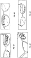
- the field expansion system can be mounted to or integrated with a spectacle lens.
- the system is mounted in an upper periphery in one lens (unilateral fitting) combined with standard fellow lens that cover the field replaced by the prism view ( FIG. 8 A-D ).
- the device is mounted on the left lens it is designed for field expansion of right hemianopia patients (blind in right half of visual field in both eyes).
- the field expansion system can be located on any desired region of the lens.
- FIG. 9 D illustrates an example field expansion system mounted in the central field of the lens.
- FIG. 9 A-D illustrates an example implementation where the field expansion system is mounted in a spectacle for right hemianopia patients.
- FIG. 9 A an example implementation with the upper prism-like device mounted at an angle of 20 degrees photographed from the front of the lens.
- FIG. 9 B illustrates the same example system viewed from the patient (e.g., wearer) side. Mounting holes can be formed through the carrier lens.
- FIG. 9 C illustrates a 3D rendered image of the final CAD design of a device for a patient with right homonymous hemianopia.
- the holder can be a transparent molded device as shown here or a silvered device.
- a lower prism can be mounted on the right lens.
- FIG. 9 D illustrates an example implementation produced with the field expansion system in the middle of the lens.
- At least one edge of the image facing surfaces can be about 13 mm. In some implementations, at least one edge of the image facing surfaces can be about 8 mm.
- the dimensions of the image facing surface can be 4 ⁇ 8 mm ( FIG. 15 C ), 8 ⁇ 8 mm ( FIG. 15 D ), and the like. In other implementations, at least one edge of the image facing surfaces can be about 4 mm.
- the dimensions of the image facing surface can be 4 ⁇ 4 mm ( FIG. 15 A ), 8 ⁇ 4 mm ( FIG. 15 D ), and the like.
- Using smaller prisms can decrease the size of the optical system 100 , decrease the curvature of the optical system (e.g., curvature associated with surfaces 140 , 143 , 146 and 148 ).
- FIG. 10 illustrates ray tracing of a hybrid design having elements of different sizes (e.g., 8 ⁇ 8 and 4 ⁇ 8 elements).
- 4 mm represents the width of the optical element (e.g., width is the dimension parallel to the plane of x-z plane in FIG. 1 )
- 8 mm represents the height of the optical element (e.g., perpendicular to the x-z plane in FIG. 1 ).
- the height of the optical element can be 8 mm, which can allow the prism to fit on a spectacle lens. For example, this can provide about 20 degrees along the height dimension (e.g, perpendicular to the x-z plane) to the expanded field (e.g., by the peripheral prism).
- the dimensions of the optical element can be based on design tradeoffs. For example, reducing the size of the optical element may result in reduction in the field of view. Increasing the size of the optical element may make it incompatible with the spectacle frame (e.g., the optical element may extend beyond the spectacle frame).
- Retinitis Pigmentosa (RP) patients suffering with tunnel vision can have a reduced field of view (e.g., the vertical field of view can be less than 10 degrees).
- An optical element having a small vertical extent e.g., 4 mm
- Reducing the height of the optical element can reduce the overall size and weight of the optical element, but may not impact the protrusion of the optical system with respect to the spectacle frame.
- the height and width of the optical elements can be independent of each other. Independent selection of height and width of the optical elements can result in smaller sizes of the optical elements with closer proximity to the carrier lens.
- Some implementations can include three 8 ⁇ 8 mm half penta prisms combined with six 4 ⁇ 8 mm half penta prisms. This design can result in a smaller and lighter device.
- the non-imaging breaks in the optical paths can be parallel.
- angular size can decrease as the distance from the user increases.
- FIG. 11 A illustrates a panoramic composite image of a street view.
- a street lamp pole is located about 30 degrees (dashed line) from the 0 degree black dashed line (indicating lens center in FIGS. 11 B and 11 C ).
- the same scene was photographed with an example implementation of the current subject matter and using a vision simulation camera to illustrate the impact of ( FIG. 11 C ) the example field expansion system and to compare both the magnitude of the shift and the image quality with ( FIG. 11 B ) a currently available conventional prism of 30 degrees deviation.
- FIG. 11 B is a photograph taken through spectacle lens with a conventional 57 prism diopter (30 degrees) peripheral upper prism for a person with right hemianopia fixating at the center of the image (black dashed line).
- FIG. 11 C illustrates a photo taken with the example implementation of field expansion system.
- the prism shift of 45 degrees brings the building (well beyond the pole of street lamp) in the blind side into the view while shifting the tree crown and the pole of the street lamp further to the left.
- the TIR limit is farther to the right (15 ⁇ 20 degrees) enabling more benefit from eye scanning into the blind side.
- FIG. 11 C illustrates an improved quality of the shifted image (higher contrast, less distortion, and less color dispersion) compared to the image in FIG. 11 B .
- Hemianopia the loss of half of the visual field on one side in both eyes, is a common result of strokes and other brain injuries, affecting 0.8% of people 50 years or older in the USA. Patients are restricted from driving in many states and countries (though they are permitted in others) and complain of other difficulties. Prisms designed to shift portions of a scene from the blind side to the residual field are simple, light, cost effective, and efficient.
- Example peripheral prism glasses include THE PELI LENSTM and THE PELI PRISMTM. These prism glasses expand the visual field by as much as 30 degrees (out of the 90 degrees lost) and significantly improve hazard detection when walking by individuals with hemianopia. In randomized controlled clinical trials, 74% of patients found the device useful; 50% continued to wear it for an extended follow-up period and had significantly improved hazards detection on the blind side in driving.
- FIG. 12 A-D illustrates differences between the principles of conventional prism and mirror-based prisms. The light rays are shown as emerging from the eye but in fact optic is reversible so the light getting to the eye can be traced on the same lines.
- the desired higher deflection light path (dashed line in FIG. 12 B for 45 degrees shift) is not available as Fresnel prism because it exceeds the critical angle and limits the effective eye scanning range even further.
- the mirror-based prism can deflect the light path at the desired higher angle with lower level distortion and better contrast and color due to the imaging based mostly on reflection instead of refraction.
- FIG. 12 A illustrates a photo of peripheral prism (PELT LENSTM), conventional Fresnel-30 degrees deflection, for hemianopia patients
- FIG. 12 B illustrates a conventional prism for 30 degrees deflection with its optical power (dashed line for desired 45 degrees deflection)
- FIG. 12 C illustrates a mirror-based prism element realizing higher optical power (45 degrees deflection) with lower artifacts
- FIG. 12 D illustrates a 3D structure of a mirror-based prism device.
- An example mirror-based prism device composed of four mirror pair modules (MO 1 ⁇ MO 4 ) as shown in the right side of FIG. 12 D that provides deflection of 45 degrees and field of view of 60 degrees.
- the size of device could be too big (up to 100 mm) and impractical to attach to glasses. Therefore, the design is divided into multiple smaller modules in a Fresnel-prism-like design. In this design, the angle of deflection derived from reflection is limited to reduce the curving and spiraling of the complete module. To compensate for that loss in deflection power, the eye facing surface of the element is tilted to add prismatic power.
- FIGS. 13 A-B illustrate ray traces of light beams from mirror-based prism device illustrated in FIG. 12 D .
- FIGS. 14 A-B illustrate visual applications of half penta prisms are in rock climbing ( FIG. 14 A ) and TV bed glasses ( FIG. 14 B ).
- Half penta prisms can also be used in keplerian telescopes and binoculars forming part visual reversing unit (for example in combination with a roof prism).
- a first unit including optical elements is produced from a single mold.
- the optical elements of the first unit are connected via their image facing surfaces to hold them together.
- a second molded unit is made to fit in between the aforementioned optical elements.
- the first and the second units are glued together and then mounted to a lens of an eye glass.
- FIGS. 15 C and 15 D illustrate half penta prisms arranged in an oblique design. Each half penta prism can be rotated around the visual axis 172 . This can result in light beams being directed into the (vertical) peripheral retinal locations coming from a more central field location. Since each half penta can be rotated, they can end up in a staggered configuration as shown in the 15 C and 15 D.
- the current subject matter is not limited to attaching to spectacles but can include other uses, such as attaching to a camera or video lens.
- the optical system can include two half penta prisms (e.g., for each eye). The first half penta prism can be located along the primary position of gaze and the second half penta prism can be located along the direction of the putative prism “base” for scanning with the eyes.
- RP patients may need only 2 half penta prisms of 8 ⁇ 4 mm for each optical system (e.g., one for the right side and one for the left side).
- a first optical system with two half penta prisms can be located above the line of sight of one eye of the patient, and a second optical system with two half penta prisms can be located below the line of sight of the second eye of the patient.
- the current subject matter can be quickly manufactured by 3D printing technology.
- the current subject matter can provide a wide angle field expansion (e.g., between 45 degrees and 60 degrees) over a wide visual field. This can reduce collision events for a person suffering from peripheral field loss.
- the current subject matter can provide dramatically better image quality and much less distortion (minification), which can improve the detection of hazard by a wearer.
- the current subject matter can enable a wider range of effective eye scanning range.
- phrases such as “at least one of” or “one or more of” may occur followed by a conjunctive list of elements or features.
- the term “and/or” may also occur in a list of two or elements or features. Unless otherwise implicitly or explicitly contradicted by the context in which it is used, such a phrase is intended to mean any of the listed elements or features individually or any of the recited elements or features in combination with any of the other recited elements or features.
- the phrases “at least one of A and B;” “one or more of A and B;” and “A and/or B” are each n tended to mean “A alone, B alone, or A and B together.”
- a similar interpretation is also intended for lists including three or more items.
- the phrases “at least one of A, B, and C;” “one or more of A, B, and C;” and “A, B, and/or C” are each intended to mean “A alone, B alone, C alone, A and B together, A and C together, B and C together, or A and B and C together.”
- use of the term “based on,” above and in the claims is intended to mean, “based at least in part on,” such that an unrecited feature or element is also permissible.
Landscapes
- Physics & Mathematics (AREA)
- Health & Medical Sciences (AREA)
- Ophthalmology & Optometry (AREA)
- General Physics & Mathematics (AREA)
- Optics & Photonics (AREA)
- General Health & Medical Sciences (AREA)
- Acoustics & Sound (AREA)
- Otolaryngology (AREA)
- Optical Elements Other Than Lenses (AREA)
- Lenses (AREA)
Abstract
Description
Claims (20)
Priority Applications (1)
| Application Number | Priority Date | Filing Date | Title |
|---|---|---|---|
| US16/754,224 US11520169B2 (en) | 2017-10-11 | 2018-10-11 | Expansion of field of view |
Applications Claiming Priority (3)
| Application Number | Priority Date | Filing Date | Title |
|---|---|---|---|
| US201762571217P | 2017-10-11 | 2017-10-11 | |
| US16/754,224 US11520169B2 (en) | 2017-10-11 | 2018-10-11 | Expansion of field of view |
| PCT/US2018/055461 WO2019075235A2 (en) | 2017-10-11 | 2018-10-11 | Expansion of field of view |
Publications (2)
| Publication Number | Publication Date |
|---|---|
| US20210199993A1 US20210199993A1 (en) | 2021-07-01 |
| US11520169B2 true US11520169B2 (en) | 2022-12-06 |
Family
ID=66100076
Family Applications (1)
| Application Number | Title | Priority Date | Filing Date |
|---|---|---|---|
| US16/754,224 Active 2039-08-23 US11520169B2 (en) | 2017-10-11 | 2018-10-11 | Expansion of field of view |
Country Status (2)
| Country | Link |
|---|---|
| US (1) | US11520169B2 (en) |
| WO (1) | WO2019075235A2 (en) |
Families Citing this family (2)
| Publication number | Priority date | Publication date | Assignee | Title |
|---|---|---|---|---|
| JP7469261B2 (en) * | 2021-06-22 | 2024-04-16 | 株式会社デンソー | Blind Spot Aid |
| US12124060B2 (en) * | 2021-12-28 | 2024-10-22 | Mloptic Corp. | Prism to enable large FOV high resolution sampling with smaller FOV imaging system |
Citations (9)
| Publication number | Priority date | Publication date | Assignee | Title |
|---|---|---|---|---|
| US3484149A (en) | 1967-04-13 | 1969-12-16 | Leitz Ernst Gmbh | Center focusing prism binocular and reticle |
| US7374284B2 (en) | 2003-12-17 | 2008-05-20 | The Schepens Eye Research Institute, Inc. | Peripheral field expansion device |
| US7817341B2 (en) | 2001-12-31 | 2010-10-19 | Texas Instruments Incorporated | Integrated TIR prism and lens element |
| US20120057242A1 (en) * | 2010-09-06 | 2012-03-08 | Koichi Takahashi | Decentration optical system, and image display apparatus and imaging apparatus incorporating the same |
| WO2014068482A1 (en) | 2012-10-30 | 2014-05-08 | Glassup S.R.L. A Capitale Ridotto | Augmented reality glasses |
| US20140340285A1 (en) * | 2013-05-15 | 2014-11-20 | Seiko Epson Corporation | Virtual image display apparatus |
| US8917459B2 (en) | 2011-05-23 | 2014-12-23 | Eric A. Klein | Ergonomic vertical vision redirection |
| US9541740B2 (en) | 2014-06-20 | 2017-01-10 | Qualcomm Incorporated | Folded optic array camera using refractive prisms |
| WO2017078860A1 (en) | 2015-11-03 | 2017-05-11 | Google Inc. | Display of binocular overlapping images in a head mounted display |
-
2018
- 2018-10-11 US US16/754,224 patent/US11520169B2/en active Active
- 2018-10-11 WO PCT/US2018/055461 patent/WO2019075235A2/en not_active Ceased
Patent Citations (9)
| Publication number | Priority date | Publication date | Assignee | Title |
|---|---|---|---|---|
| US3484149A (en) | 1967-04-13 | 1969-12-16 | Leitz Ernst Gmbh | Center focusing prism binocular and reticle |
| US7817341B2 (en) | 2001-12-31 | 2010-10-19 | Texas Instruments Incorporated | Integrated TIR prism and lens element |
| US7374284B2 (en) | 2003-12-17 | 2008-05-20 | The Schepens Eye Research Institute, Inc. | Peripheral field expansion device |
| US20120057242A1 (en) * | 2010-09-06 | 2012-03-08 | Koichi Takahashi | Decentration optical system, and image display apparatus and imaging apparatus incorporating the same |
| US8917459B2 (en) | 2011-05-23 | 2014-12-23 | Eric A. Klein | Ergonomic vertical vision redirection |
| WO2014068482A1 (en) | 2012-10-30 | 2014-05-08 | Glassup S.R.L. A Capitale Ridotto | Augmented reality glasses |
| US20140340285A1 (en) * | 2013-05-15 | 2014-11-20 | Seiko Epson Corporation | Virtual image display apparatus |
| US9541740B2 (en) | 2014-06-20 | 2017-01-10 | Qualcomm Incorporated | Folded optic array camera using refractive prisms |
| WO2017078860A1 (en) | 2015-11-03 | 2017-05-11 | Google Inc. | Display of binocular overlapping images in a head mounted display |
Non-Patent Citations (1)
| Title |
|---|
| "High-Power Prismatic Devices May Further Expand Visual Fields for Patients with Hemianopia", Massachusetts Eye and Ear, May 17, 2016, 4 pages. |
Also Published As
| Publication number | Publication date |
|---|---|
| WO2019075235A3 (en) | 2019-05-31 |
| US20210199993A1 (en) | 2021-07-01 |
| WO2019075235A2 (en) | 2019-04-18 |
Similar Documents
| Publication | Publication Date | Title |
|---|---|---|
| US5724163A (en) | Optical system for alternative or simultaneous direction of light originating from two scenes to the eye of a viewer | |
| CN102004317B (en) | Spectacles-type image display device | |
| US11513349B2 (en) | Optical see-through (OST) near-eye display (NED) system integrating ophthalmic correction | |
| US9681804B2 (en) | Hybrid lens system for head wearable display | |
| US20120013988A1 (en) | Head mounted display having a panoramic field of view | |
| US11175483B2 (en) | Wide field of view head mounted display | |
| CN106662745A (en) | Compact architecture for near-to-eye display system | |
| KR20180015620A (en) | Efficient thin curved eyepiece for see-through head wearable display | |
| US4779972A (en) | Method of using a prism in lens for the treatment of visual field loss | |
| KR102919429B1 (en) | An optical fluoroscopy (OST) near-vision display (NED) system that integrates ophthalmic correction. | |
| WO2016141720A1 (en) | Optical amplification combined lens, head-mounted optical display system and virtual reality display device | |
| CN218917840U (en) | Defocused display glasses | |
| US20160004101A1 (en) | Vision Modification Based on a Multiplexing Prism | |
| US11520169B2 (en) | Expansion of field of view | |
| JP2004537068A (en) | Bifocal telephoto lens system embedded in eyeglass lens | |
| US20080259272A1 (en) | Eyewear for Redirected Viewing | |
| Falahati et al. | Oblique multi-periscopic prism for field expansion of homonymous hemianopia | |
| US12105292B2 (en) | Optical see through (OST) near eye display (NED) system integrating ophthalmic correction | |
| JP2019168672A (en) | Cloaking devices with half fresnel lenses and plane mirrors, and vehicles comprising the same | |
| US9857592B2 (en) | Display device | |
| CN222939350U (en) | Cascade prism vision aid | |
| US20250035935A1 (en) | Optical see through (ost) near eye display (ned) system integrating ophthalmic correction | |
| CN1342911A (en) | Reflective steroscopic glasses | |
| US20230194841A1 (en) | Augmented reality display device | |
| JP4255454B2 (en) | Field expansion tool and field expansion glasses |
Legal Events
| Date | Code | Title | Description |
|---|---|---|---|
| FEPP | Fee payment procedure |
Free format text: ENTITY STATUS SET TO UNDISCOUNTED (ORIGINAL EVENT CODE: BIG.); ENTITY STATUS OF PATENT OWNER: SMALL ENTITY |
|
| FEPP | Fee payment procedure |
Free format text: ENTITY STATUS SET TO SMALL (ORIGINAL EVENT CODE: SMAL); ENTITY STATUS OF PATENT OWNER: SMALL ENTITY |
|
| AS | Assignment |
Owner name: THE UNIVERSITY OF MURCIA, SPAIN Free format text: ASSIGNMENT OF ASSIGNORS INTEREST;ASSIGNOR:VARGAS-MARTIN, FERNANDO;REEL/FRAME:053228/0623 Effective date: 20180312 Owner name: THE SCHEPENS EYE RESEARCH INSTITUTE, INC., MASSACHUSETTS Free format text: ASSIGNMENT OF ASSIGNORS INTEREST;ASSIGNOR:PELI, ELIEZER;REEL/FRAME:053229/0270 Effective date: 20171220 |
|
| STPP | Information on status: patent application and granting procedure in general |
Free format text: APPLICATION DISPATCHED FROM PREEXAM, NOT YET DOCKETED |
|
| STPP | Information on status: patent application and granting procedure in general |
Free format text: DOCKETED NEW CASE - READY FOR EXAMINATION |
|
| STPP | Information on status: patent application and granting procedure in general |
Free format text: NON FINAL ACTION MAILED |
|
| STPP | Information on status: patent application and granting procedure in general |
Free format text: RESPONSE TO NON-FINAL OFFICE ACTION ENTERED AND FORWARDED TO EXAMINER |
|
| STPP | Information on status: patent application and granting procedure in general |
Free format text: NOTICE OF ALLOWANCE MAILED -- APPLICATION RECEIVED IN OFFICE OF PUBLICATIONS |
|
| STPP | Information on status: patent application and granting procedure in general |
Free format text: PUBLICATIONS -- ISSUE FEE PAYMENT VERIFIED |
|
| STCF | Information on status: patent grant |
Free format text: PATENTED CASE |