US11513621B2 - Display apparatus - Google Patents
Display apparatus Download PDFInfo
- Publication number
- US11513621B2 US11513621B2 US15/734,137 US201815734137A US11513621B2 US 11513621 B2 US11513621 B2 US 11513621B2 US 201815734137 A US201815734137 A US 201815734137A US 11513621 B2 US11513621 B2 US 11513621B2
- Authority
- US
- United States
- Prior art keywords
- sensor
- main frame
- display apparatus
- rods
- panel
- Prior art date
- Legal status (The legal status is an assumption and is not a legal conclusion. Google has not performed a legal analysis and makes no representation as to the accuracy of the status listed.)
- Active
Links
Images


Classifications
-
- G—PHYSICS
- G06—COMPUTING OR CALCULATING; COUNTING
- G06F—ELECTRIC DIGITAL DATA PROCESSING
- G06F1/00—Details not covered by groups G06F3/00 - G06F13/00 and G06F21/00
- G06F1/16—Constructional details or arrangements
- G06F1/1613—Constructional details or arrangements for portable computers
- G06F1/1633—Constructional details or arrangements of portable computers not specific to the type of enclosures covered by groups G06F1/1615 - G06F1/1626
- G06F1/1637—Details related to the display arrangement, including those related to the mounting of the display in the housing
- G06F1/1643—Details related to the display arrangement, including those related to the mounting of the display in the housing the display being associated to a digitizer, e.g. laptops that can be used as penpads
-
- G—PHYSICS
- G06—COMPUTING OR CALCULATING; COUNTING
- G06F—ELECTRIC DIGITAL DATA PROCESSING
- G06F3/00—Input arrangements for transferring data to be processed into a form capable of being handled by the computer; Output arrangements for transferring data from processing unit to output unit, e.g. interface arrangements
- G06F3/01—Input arrangements or combined input and output arrangements for interaction between user and computer
- G06F3/03—Arrangements for converting the position or the displacement of a member into a coded form
- G06F3/041—Digitisers, e.g. for touch screens or touch pads, characterised by the transducing means
- G06F3/0412—Digitisers structurally integrated in a display
-
- B—PERFORMING OPERATIONS; TRANSPORTING
- B60—VEHICLES IN GENERAL
- B60K—ARRANGEMENT OR MOUNTING OF PROPULSION UNITS OR OF TRANSMISSIONS IN VEHICLES; ARRANGEMENT OR MOUNTING OF PLURAL DIVERSE PRIME-MOVERS IN VEHICLES; AUXILIARY DRIVES FOR VEHICLES; INSTRUMENTATION OR DASHBOARDS FOR VEHICLES; ARRANGEMENTS IN CONNECTION WITH COOLING, AIR INTAKE, GAS EXHAUST OR FUEL SUPPLY OF PROPULSION UNITS IN VEHICLES
- B60K35/00—Instruments specially adapted for vehicles; Arrangement of instruments in or on vehicles
- B60K35/10—Input arrangements, i.e. from user to vehicle, associated with vehicle functions or specially adapted therefor
-
- B—PERFORMING OPERATIONS; TRANSPORTING
- B60—VEHICLES IN GENERAL
- B60K—ARRANGEMENT OR MOUNTING OF PROPULSION UNITS OR OF TRANSMISSIONS IN VEHICLES; ARRANGEMENT OR MOUNTING OF PLURAL DIVERSE PRIME-MOVERS IN VEHICLES; AUXILIARY DRIVES FOR VEHICLES; INSTRUMENTATION OR DASHBOARDS FOR VEHICLES; ARRANGEMENTS IN CONNECTION WITH COOLING, AIR INTAKE, GAS EXHAUST OR FUEL SUPPLY OF PROPULSION UNITS IN VEHICLES
- B60K35/00—Instruments specially adapted for vehicles; Arrangement of instruments in or on vehicles
- B60K35/20—Output arrangements, i.e. from vehicle to user, associated with vehicle functions or specially adapted therefor
- B60K35/21—Output arrangements, i.e. from vehicle to user, associated with vehicle functions or specially adapted therefor using visual output, e.g. blinking lights or matrix displays
- B60K35/22—Display screens
-
- B—PERFORMING OPERATIONS; TRANSPORTING
- B60—VEHICLES IN GENERAL
- B60K—ARRANGEMENT OR MOUNTING OF PROPULSION UNITS OR OF TRANSMISSIONS IN VEHICLES; ARRANGEMENT OR MOUNTING OF PLURAL DIVERSE PRIME-MOVERS IN VEHICLES; AUXILIARY DRIVES FOR VEHICLES; INSTRUMENTATION OR DASHBOARDS FOR VEHICLES; ARRANGEMENTS IN CONNECTION WITH COOLING, AIR INTAKE, GAS EXHAUST OR FUEL SUPPLY OF PROPULSION UNITS IN VEHICLES
- B60K35/00—Instruments specially adapted for vehicles; Arrangement of instruments in or on vehicles
- B60K35/20—Output arrangements, i.e. from vehicle to user, associated with vehicle functions or specially adapted therefor
- B60K35/25—Output arrangements, i.e. from vehicle to user, associated with vehicle functions or specially adapted therefor using haptic output
-
- B—PERFORMING OPERATIONS; TRANSPORTING
- B60—VEHICLES IN GENERAL
- B60K—ARRANGEMENT OR MOUNTING OF PROPULSION UNITS OR OF TRANSMISSIONS IN VEHICLES; ARRANGEMENT OR MOUNTING OF PLURAL DIVERSE PRIME-MOVERS IN VEHICLES; AUXILIARY DRIVES FOR VEHICLES; INSTRUMENTATION OR DASHBOARDS FOR VEHICLES; ARRANGEMENTS IN CONNECTION WITH COOLING, AIR INTAKE, GAS EXHAUST OR FUEL SUPPLY OF PROPULSION UNITS IN VEHICLES
- B60K35/00—Instruments specially adapted for vehicles; Arrangement of instruments in or on vehicles
- B60K35/50—Instruments characterised by their means of attachment to or integration in the vehicle
-
- B—PERFORMING OPERATIONS; TRANSPORTING
- B60—VEHICLES IN GENERAL
- B60K—ARRANGEMENT OR MOUNTING OF PROPULSION UNITS OR OF TRANSMISSIONS IN VEHICLES; ARRANGEMENT OR MOUNTING OF PLURAL DIVERSE PRIME-MOVERS IN VEHICLES; AUXILIARY DRIVES FOR VEHICLES; INSTRUMENTATION OR DASHBOARDS FOR VEHICLES; ARRANGEMENTS IN CONNECTION WITH COOLING, AIR INTAKE, GAS EXHAUST OR FUEL SUPPLY OF PROPULSION UNITS IN VEHICLES
- B60K35/00—Instruments specially adapted for vehicles; Arrangement of instruments in or on vehicles
- B60K35/60—Instruments characterised by their location or relative disposition in or on vehicles
-
- G—PHYSICS
- G06—COMPUTING OR CALCULATING; COUNTING
- G06F—ELECTRIC DIGITAL DATA PROCESSING
- G06F1/00—Details not covered by groups G06F3/00 - G06F13/00 and G06F21/00
- G06F1/16—Constructional details or arrangements
- G06F1/1601—Constructional details related to the housing of computer displays, e.g. of CRT monitors, of flat displays
-
- G—PHYSICS
- G06—COMPUTING OR CALCULATING; COUNTING
- G06F—ELECTRIC DIGITAL DATA PROCESSING
- G06F3/00—Input arrangements for transferring data to be processed into a form capable of being handled by the computer; Output arrangements for transferring data from processing unit to output unit, e.g. interface arrangements
- G06F3/01—Input arrangements or combined input and output arrangements for interaction between user and computer
- G06F3/016—Input arrangements with force or tactile feedback as computer generated output to the user
-
- G—PHYSICS
- G06—COMPUTING OR CALCULATING; COUNTING
- G06F—ELECTRIC DIGITAL DATA PROCESSING
- G06F3/00—Input arrangements for transferring data to be processed into a form capable of being handled by the computer; Output arrangements for transferring data from processing unit to output unit, e.g. interface arrangements
- G06F3/01—Input arrangements or combined input and output arrangements for interaction between user and computer
- G06F3/03—Arrangements for converting the position or the displacement of a member into a coded form
- G06F3/041—Digitisers, e.g. for touch screens or touch pads, characterised by the transducing means
-
- B—PERFORMING OPERATIONS; TRANSPORTING
- B60—VEHICLES IN GENERAL
- B60K—ARRANGEMENT OR MOUNTING OF PROPULSION UNITS OR OF TRANSMISSIONS IN VEHICLES; ARRANGEMENT OR MOUNTING OF PLURAL DIVERSE PRIME-MOVERS IN VEHICLES; AUXILIARY DRIVES FOR VEHICLES; INSTRUMENTATION OR DASHBOARDS FOR VEHICLES; ARRANGEMENTS IN CONNECTION WITH COOLING, AIR INTAKE, GAS EXHAUST OR FUEL SUPPLY OF PROPULSION UNITS IN VEHICLES
- B60K2360/00—Indexing scheme associated with groups B60K35/00 or B60K37/00 relating to details of instruments or dashboards
- B60K2360/143—Touch sensitive instrument input devices
- B60K2360/1438—Touch screens
-
- B60K2370/1438—
-
- B60K2370/158—
-
- G—PHYSICS
- G01—MEASURING; TESTING
- G01L—MEASURING FORCE, STRESS, TORQUE, WORK, MECHANICAL POWER, MECHANICAL EFFICIENCY, OR FLUID PRESSURE
- G01L1/00—Measuring force or stress, in general
- G01L1/20—Measuring force or stress, in general by measuring variations in ohmic resistance of solid materials or of electrically-conductive fluids; by making use of electrokinetic cells, i.e. liquid-containing cells wherein an electrical potential is produced or varied upon the application of stress
- G01L1/22—Measuring force or stress, in general by measuring variations in ohmic resistance of solid materials or of electrically-conductive fluids; by making use of electrokinetic cells, i.e. liquid-containing cells wherein an electrical potential is produced or varied upon the application of stress using resistance strain gauges
-
- G—PHYSICS
- G02—OPTICS
- G02F—OPTICAL DEVICES OR ARRANGEMENTS FOR THE CONTROL OF LIGHT BY MODIFICATION OF THE OPTICAL PROPERTIES OF THE MEDIA OF THE ELEMENTS INVOLVED THEREIN; NON-LINEAR OPTICS; FREQUENCY-CHANGING OF LIGHT; OPTICAL LOGIC ELEMENTS; OPTICAL ANALOGUE/DIGITAL CONVERTERS
- G02F1/00—Devices or arrangements for the control of the intensity, colour, phase, polarisation or direction of light arriving from an independent light source, e.g. switching, gating or modulating; Non-linear optics
- G02F1/01—Devices or arrangements for the control of the intensity, colour, phase, polarisation or direction of light arriving from an independent light source, e.g. switching, gating or modulating; Non-linear optics for the control of the intensity, phase, polarisation or colour
- G02F1/13—Devices or arrangements for the control of the intensity, colour, phase, polarisation or direction of light arriving from an independent light source, e.g. switching, gating or modulating; Non-linear optics for the control of the intensity, phase, polarisation or colour based on liquid crystals, e.g. single liquid crystal display cells
- G02F1/133—Constructional arrangements; Operation of liquid crystal cells; Circuit arrangements
- G02F1/1333—Constructional arrangements; Manufacturing methods
- G02F1/133308—Support structures for LCD panels, e.g. frames or bezels
- G02F1/133314—Back frames
-
- G—PHYSICS
- G02—OPTICS
- G02F—OPTICAL DEVICES OR ARRANGEMENTS FOR THE CONTROL OF LIGHT BY MODIFICATION OF THE OPTICAL PROPERTIES OF THE MEDIA OF THE ELEMENTS INVOLVED THEREIN; NON-LINEAR OPTICS; FREQUENCY-CHANGING OF LIGHT; OPTICAL LOGIC ELEMENTS; OPTICAL ANALOGUE/DIGITAL CONVERTERS
- G02F1/00—Devices or arrangements for the control of the intensity, colour, phase, polarisation or direction of light arriving from an independent light source, e.g. switching, gating or modulating; Non-linear optics
- G02F1/01—Devices or arrangements for the control of the intensity, colour, phase, polarisation or direction of light arriving from an independent light source, e.g. switching, gating or modulating; Non-linear optics for the control of the intensity, phase, polarisation or colour
- G02F1/13—Devices or arrangements for the control of the intensity, colour, phase, polarisation or direction of light arriving from an independent light source, e.g. switching, gating or modulating; Non-linear optics for the control of the intensity, phase, polarisation or colour based on liquid crystals, e.g. single liquid crystal display cells
- G02F1/133—Constructional arrangements; Operation of liquid crystal cells; Circuit arrangements
- G02F1/1333—Constructional arrangements; Manufacturing methods
- G02F1/133308—Support structures for LCD panels, e.g. frames or bezels
- G02F1/133317—Intermediate frames, e.g. between backlight housing and front frame
-
- G—PHYSICS
- G02—OPTICS
- G02F—OPTICAL DEVICES OR ARRANGEMENTS FOR THE CONTROL OF LIGHT BY MODIFICATION OF THE OPTICAL PROPERTIES OF THE MEDIA OF THE ELEMENTS INVOLVED THEREIN; NON-LINEAR OPTICS; FREQUENCY-CHANGING OF LIGHT; OPTICAL LOGIC ELEMENTS; OPTICAL ANALOGUE/DIGITAL CONVERTERS
- G02F1/00—Devices or arrangements for the control of the intensity, colour, phase, polarisation or direction of light arriving from an independent light source, e.g. switching, gating or modulating; Non-linear optics
- G02F1/01—Devices or arrangements for the control of the intensity, colour, phase, polarisation or direction of light arriving from an independent light source, e.g. switching, gating or modulating; Non-linear optics for the control of the intensity, phase, polarisation or colour
- G02F1/13—Devices or arrangements for the control of the intensity, colour, phase, polarisation or direction of light arriving from an independent light source, e.g. switching, gating or modulating; Non-linear optics for the control of the intensity, phase, polarisation or colour based on liquid crystals, e.g. single liquid crystal display cells
- G02F1/133—Constructional arrangements; Operation of liquid crystal cells; Circuit arrangements
- G02F1/1333—Constructional arrangements; Manufacturing methods
- G02F1/133308—Support structures for LCD panels, e.g. frames or bezels
- G02F1/133322—Mechanical guidance or alignment of LCD panel support components
-
- G—PHYSICS
- G06—COMPUTING OR CALCULATING; COUNTING
- G06F—ELECTRIC DIGITAL DATA PROCESSING
- G06F1/00—Details not covered by groups G06F3/00 - G06F13/00 and G06F21/00
- G06F1/16—Constructional details or arrangements
- G06F1/1613—Constructional details or arrangements for portable computers
- G06F1/1633—Constructional details or arrangements of portable computers not specific to the type of enclosures covered by groups G06F1/1615 - G06F1/1626
- G06F1/1637—Details related to the display arrangement, including those related to the mounting of the display in the housing
-
- G—PHYSICS
- G06—COMPUTING OR CALCULATING; COUNTING
- G06F—ELECTRIC DIGITAL DATA PROCESSING
- G06F2203/00—Indexing scheme relating to G06F3/00 - G06F3/048
- G06F2203/041—Indexing scheme relating to G06F3/041 - G06F3/045
- G06F2203/04103—Manufacturing, i.e. details related to manufacturing processes specially suited for touch sensitive devices
-
- G—PHYSICS
- G06—COMPUTING OR CALCULATING; COUNTING
- G06F—ELECTRIC DIGITAL DATA PROCESSING
- G06F2203/00—Indexing scheme relating to G06F3/00 - G06F3/048
- G06F2203/041—Indexing scheme relating to G06F3/041 - G06F3/045
- G06F2203/04105—Pressure sensors for measuring the pressure or force exerted on the touch surface without providing the touch position
-
- G—PHYSICS
- G06—COMPUTING OR CALCULATING; COUNTING
- G06F—ELECTRIC DIGITAL DATA PROCESSING
- G06F3/00—Input arrangements for transferring data to be processed into a form capable of being handled by the computer; Output arrangements for transferring data from processing unit to output unit, e.g. interface arrangements
- G06F3/01—Input arrangements or combined input and output arrangements for interaction between user and computer
- G06F3/03—Arrangements for converting the position or the displacement of a member into a coded form
- G06F3/041—Digitisers, e.g. for touch screens or touch pads, characterised by the transducing means
- G06F3/0414—Digitisers, e.g. for touch screens or touch pads, characterised by the transducing means using force sensing means to determine a position
- G06F3/04142—Digitisers, e.g. for touch screens or touch pads, characterised by the transducing means using force sensing means to determine a position the force sensing means being located peripherally, e.g. disposed at the corners or at the side of a touch sensing plate
Definitions
- the present disclosure relates to a display apparatus, and more particularly, to a display apparatus that senses a pressure, applied to a display panel by a user's touch, using a force sensor.
- a display apparatus is installed even in a vehicle, and a user operates the display apparatus using a touch sensor or a force sensor.
- a force sensor according to a related art is disposed in several layers behind the display module, there are problems that the force sensor has a complicated structure and increases a thickness of the display apparatus.
- Korean Patent Application Publication No. 10-2010-0129420 discloses a display apparatus having a pressure sensor that senses a touch pressure by measuring deformation of a metal resistance layer on the side of a free end of the force sensor so that a force sensor module can be slim.
- the related art has problems in that it is not possible to uniformly sense a pressure of a user's touch pressure regardless of a position of the user's touch because the force sensor is disposed at an edge of the display and that a large number of force sensors are required.
- the related art has a problem in that it is difficult to accurately install a force sensor at a predetermined design position.
- the related art has a problem in that the force sensor cannot operate accurately due to fatigue during long-term use.
- a display apparatus including a display panel; a guide panel coupled to a rear surface of the display panel; a main frame coupled to the guide panel; and a force sensor module located between the guide panel and the main frame, wherein the force sensor module comprises: a sensor bar including a sensor rod disposed to be inclined from a central portion of the main frame toward a peripheral portion of the main frame; and a strain gauge installed on each of the plurality of sensor rods.
- the sensor bar may be symmetrically disposed to each other in up-downward direction and a left-rightward direction.
- Each of the sensor bar may be disposed in a diagonal direction of the main frame.
- the sensor bar may include a stem rod, and the sensor rod may extend outwardly from both ends of the stem rod.
- the stem rod may be disposed in a vertical or horizontal direction of the main frame.
- the sensor bar may be a pair of sensor bars disposed to be vertically and horizontally symmetrical to each other.
- a stem recession into which the stem rod is inserted may be formed in the main frame.
- a guide hole may be formed in one of the stem rod and the main frame, and a protrusion to be inserted into the guide hole is formed in the other one of the stem rod and the main frame.
- An inner end of the sensor rod may be fixed to the main frame, and an outer end of the sensor rod may be disposed to be spaced apart from a bottom surface of the main frame so as to be movable toward the main frame.
- the outer end of the sensor rod may be fixed to the guide panel.
- the guide panel may have a boss protruding rearward, and the outer end of the sensor rod is fixed to the boss.
- the main frame may have an opening formed at a position corresponding to the outer end of the sensor rod, so that a fastening member passes through the opening and is then fastened to the sensor rod and the boss.
- sensor rods included in a force sensor module are disposed to be inclined from the center toward the periphery of a main frame, it is possible to reduce deviation in detected pressure according to a position which a user touches on a display panel.
- FIG. 1 is a perspective view of a display apparatus according to an embodiment of the present disclosure.
- FIG. 2 is an exploded perspective view of a display apparatus according to an embodiment of the present disclosure.
- FIG. 3 is a front view of a sensor bar according to an embodiment of the present disclosure.
- FIG. 4 is a front view of a main frame according to an embodiment of the present disclosure.
- FIG. 5 is a front view of a main frame to which a sensor bar according to an embodiment of the present disclosure is coupled.
- FIG. 6 is a rear view and a side view of a guide panel according to an embodiment of the present disclosure.
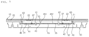
- FIG. 7 is a sectional view taken along line a-a in FIG. 5 .
- FIG. 8 is a front view of a sensor bar according to another embodiment of the present disclosure.
- FIG. 9 is a front view of a main frame to which a sensor bar according to another embodiment of the present disclosure is coupled.
- a vehicle described in the present specification may include an automobile and a motorcycle.
- a description will be given based on an automobile.
- a vehicle as described in this specification may include all of an internal combustion engine vehicle including an engine as a power source, a hybrid vehicle including both an engine and an electric motor as a power source, and an electric vehicle including an electric motor as a power source.
- FIG. 1 is a perspective view of a display apparatus according to an embodiment of the present disclosure.
- FIG. 2 is an exploded perspective view of a display apparatus according to an embodiment of the present disclosure.
- FIG. 3 is a front view of a sensor bar according to an embodiment of the present disclosure.
- FIG. 4 is a front view of a main frame according to an embodiment of the present disclosure.
- FIG. 5 is a front view of a main frame to which a sensor bar according to an embodiment of the present disclosure is coupled.
- FIG. 6 is a rear view and a side view of a guide panel according to an embodiment of the present disclosure.
- FIG. 7 is a sectional view taken along line a-a in FIG. 5 .
- a display apparatus according to a first embodiment of the present disclosure will be described below with reference to FIGS. 1 to 7 .
- the display apparatus may be provided inside a vehicle.
- the display apparatus may include a display module comprised of a display panel 10 and a guide panel 20 , a main frame 40 coupled to a rear surface of the display module, a back cover 50 , and a force sensor module 30 located between the guide panel 20 and the main frame 40 to sense a pressure applied to the display panel 10 by a user's touch.
- the display panel 10 may include an Organic Light-Emitting Diode (OLED) or a Liquid Crystal Display (LCD).
- OLED Organic Light-Emitting Diode
- LCD Liquid Crystal Display
- the display panel 10 may include a touch screen (not shown).
- the pressure applied to the display panel 10 by the user's touch may be converted into an electrical signal and provided to a processor mounted on a printed circuit board (PCB) electrically connected to the touch screen.
- PCB printed circuit board
- the display panel 10 may be covered by a cover glass (not shown).
- the cover glass may be directly touched by the user.
- the cover glass may be formed of a transparent material and may have a predetermined thickness.
- the guide panel 20 may be located at the rear surface of the display panel 10 .
- the guide panel 20 may be formed in a rectangular shape.
- the guide panel 20 not only provides a space in which a boss 21 and a haptic module 22 to be described later can be mounted, but also has an advantageous effect in preventing damage to the display panel 10 from an external impact.
- the shape of the guide panel 20 is not limited thereto.
- the guide panel 20 may be coupled to the display panel 10 , which includes OLEDs, by using an Optically Clear Adhesive (OCA) as a medium.
- OCA Optically Clear Adhesive
- the guide panel 20 may be coupled to the display panel 10 , which includes LCDs, by using an Optically Clear Resin (OCR) as a medium.
- OCR Optically Clear Resin
- the guide panel 20 may include the boss 21 and the haptic module 22 .
- the boss 21 may be formed to protrude rearward of the guide panel 20 .
- At least one boss 21 may be located at a rear surface of the guide panel 20 .
- the boss 21 may have a threaded line formed in an inner circumferential surface. In this case, an outer end of a first sensor rod 31 , 32 which will be described later may be fixed to the boss 21 .
- At least one haptic module 22 may be located at the rear surface of the guide panel 20 .
- the haptic module 22 may include a haptic actuator (not shown).
- the haptic actuator may provide haptic effects to the display panel 10 based on an electrical signal corresponding to a pressure applied to the display panel 10 by a user's touch.
- the pressure applied to the display panel 10 by the user's touch may be converted into an electrical signal and then provided to a processor mounted on a PCB electrically connected to the haptic module 22 .
- the haptic module 22 may provide haptic effects to the display panel 10 by a haptic actuator based on the electrical signal provided to the processor.
- the haptic module 22 may be located so as not to overlap more than one area with a sensor bar 30 a , 30 b which will be described later.
- the force sensor module 30 may be located between the guide panel 20 and the main frame 40 which will be described later.
- the force sensor module 30 may sense a pressure applied to the display panel 10 by the user's touch.
- the force sensor module 30 may include two sensor bars 30 a , 30 b provided with sensor rods 31 , 32 , 33 , 34 disposed to be inclined from the central portion toward the edge of the main frame 40 , and four strain gages 37 respectively installed at the sensor rods 31 , 32 , 33 , 34 .
- the sensor bars 30 a , 30 b may be formed of a metal material, particularly aluminum (Al). However, the material of the sensor bars 30 a , 30 b is not limited thereto.
- the sensor bars 30 a , 30 b may include a first sensor bar 30 a and a second sensor bar 30 b , which are spaced apart from each other on the left and right sides.
- the first sensor bar 30 a may include a first upper sensor rod 31 located on an upper side, a first lower sensor rod 32 located on a lower side, and a first stem rod 35 connecting the first upper and lower sensor rods 31 , 32 in a vertical direction.
- the first stem rod 35 may serve to connect and integrate the first upper and lower sensor rods 31 , 32 spaced apart from each other and disposed to be vertically symmetrical to each other. As a result, it may be advantageous in management and positioning adjustment of the first sensor bar 30 a.
- the first upper sensor rod 31 may be formed to extend to be inclined in a left-upward direction from an upper end of the first stem rod 35
- the first lower sensor rod 32 may be formed to extend to be inclined in a left-downward direction from a lower end of the first stem rod 35 .
- a line connecting an inner end and an outer end of each of the first upper and lower sensor rods 31 , 32 may not be parallel to the horizontal and vertical directions of the main frame 40 .
- the angle formed between each of the first upper and lower sensor rods 31 , 32 and the first stem rod 35 may be 100° to 150°, and hence, the first sensor bar 30 a may be formed in the shape of “D”, as shown in FIG. 3 .
- the directions in which the first upper and lower sensor rods 31 , 32 extend may vary according to a horizontal or vertical width of the main frame 40 .
- first upper and lower sensor rods 31 , 32 are preferably formed to be vertically symmetrical to each other with respect to a horizontal line passing through the central portion of the first stem rod 35 .
- the second sensor bar 30 b located on the right side may also include second upper and lower sensor rods 33 and 34 and a second stem rod 36 .
- the sensor rods 31 , 32 , 33 , 34 are located parallel to a longitudinal or transverse direction of the main frame 40 , it may be advantageous in precisely measuring deformation of the sensor rods 31 , 32 , 33 , 34 caused by a pressure applied to the display panel 10 by the user's touch.
- the strain gage 37 which will be described later may be able to uniformly measure a pressure applied to the display panel 10 by the user's touch.
- a guide hole 351 , 352 may be formed at both ends of the first stem rod 35 , respectively.
- first upper and lower sensor rods 31 , 32 may each have a first fastening hole 311 , 312 formed at an inner end and a second fastening hole 312 , 322 formed at an outer ends.
- a third fastening hole 313 , 323 may be formed in a bent portion protruding from the outer end to the central portion of the first upper and lower sensor rods 31 , 32 .
- the guide hole 351 , 352 , the first fastening hole 311 , 312 , the second fastening hole 312 , 322 , and the third fastening hole 313 , 323 will be described later.
- the strain gauge 37 may sense a pressure applied to the display panel 10 and the guide panel 20 by a user's touch.
- the strain gauge 37 may sense a pressure applied to the sensor rod 31 , 32 , 33 , 34 by measuring a change in electrical resistance caused by deformation of the sensor rod 31 , 32 , 33 , 34 .
- the strain gauge 37 is preferably located at a position where deformation (rate) of the sensor rod 31 , 32 , 33 , 34 is great.
- the strain gauge 37 may be located at the sensor rod 31 , 32 , 33 , 34 .
- the strain gauge 37 may include a signal transmitter 38 .
- the strain gauge 37 may be connected to a PCB panel located at the main frame 40 through the signal transmitter 38 .
- the signal transmitter 38 may transmit an input value, sensed by the strain gauge 37 , to the PCB panel located at the main frame 40 .
- the signal transmitter 38 may be configured as a flexible printed circuit board (FPCB).
- FPCB flexible printed circuit board
- the signal transmitter 38 may have at least one bent portion.
- the angle at which the signal transmitter 38 is bent may vary depending on a position of the strain gage 37 on the sensor rod 31 , 32 , 33 , 34 and a position of a connecting terminal on the PCB panel, to which the signal transmitter 38 is connected.
- the main frame 40 at which the sensor bar 30 a , 30 b is installed will be described with reference to FIGS. 4, 5 and 7 as follows.
- a first stem recession 45 may be formed in a vertical direction in a way to be recessed rearward from a front surface of the main frame 40 , so that the first stem rod 35 can be inserted into the first stem recession 45 and placed therein.
- a first upper recession 41 may be formed in a left-upward direction from an upper end of the first stem recession 45
- a first lower recession 41 may be formed in a left-downward direction from a lower end of the first stem recession 42 , and thus, the first upper and lower sensor rods 31 , 32 may be inserted into the first upper and lower recessions 41 , 42 .
- the first upper and lower recessions 41 , 42 may include portions into which inner ends of the first upper and lower sensor rods 31 , 32 are inserted and placed, and portions into which the outer ends of the first upper and lower sensor rods 31 , 32 are inserted.
- Portions of the first upper and lower recessions 41 , 42 into which the inner ends of the first upper and lower sensor rods 31 , 32 are inserted and placed may be formed to be recessed rearward from the front surface of the main frame 40 by the same depth of the first stem recession 45 .
- first upper and lower recessions 41 , 42 may be formed to be recessed further rearward from the front surface of the main frame 40 than the first stem recession 45 .
- a rear surface of the first stem rod 35 may be placed on the first stem recession 45 to contact a bottom surface of the first stem recession 45 , and rear surfaces of the inner ends of the first upper and lower sensor rods 31 , 32 may be placed to contact the bottom surfaces of the portions of the first and lower recessions 41 , 42 , the portions into which the inner ends of the first upper and lower sensor rods 31 , 32 are inserted.
- rear surfaces of portions other than the inner ends of the first upper and lower sensor rods 31 , 32 may be spaced a predetermined distance apart from the bottom surfaces of the portions of the first upper and lower recessions 41 , 42 into which the inner ends of the first upper and lower sensor rods 31 , 32 are inserted and placed, and thus, the rear surfaces of the other portions of the first upper and lower sensor rods 31 , 32 may move the predetermined distance rearward.
- the distance by which the first upper and lower sensor rods 31 , 32 are spaced apart from the bottom surfaces of the first upper and lower recessions 41 , 42 may be about 1 mm, but the separation distance is not limited thereto and may vary depending on a thickness or a deformation range of the first upper and lower sensor rods 31 , 32 .
- the recession may prevent the sensor bar 30 a , 30 b from being out of a fixed position thereof after the sensor bar 30 a , 30 b is fixed to the main frame 40 .
- first and second protrusions 451 , 452 may be formed at positions corresponding to first and second guide holes 351 , 352 formed in the first stem rod 35 .
- a first fastening aperture 411 and 421 may be formed at a position corresponding to the first fastening hole 311 , 321 formed in the first upper and lower sensor rods 31 , 32 .
- the first fastening hole 311 , 321 and the first fastening aperture 411 , 421 may be matched.
- the first sensor bar 30 a may be fixedly installed on the main frame 40 .
- the first sensor bar 30 a may be simply and tightly coupled at a predetermined position on the main frame 40 .
- the third fastening hole 313 may also serve to allow the sensor bar 30 a , 30 b to be simply and tightly fastened at the predetermined position on the main frame 40 .
- a second stem recession 47 and second upper and lower recessions 43 , 44 may be formed to correspond to the second sensor bar 30 b , and the second sensor bar 30 b may be also inserted into the aforementioned recession to be fixedly installed on the main frame 40 , and the specific coupling structure and coupling method thereof are the same as those of the first sensor bar 30 a , and thus a further description will be omitted.
- Reference numeral 46 indicates an opening formed at a position on the main frame 40 , which corresponds to the second fastening hole 312 , 322 formed at the outer end of the first upper and lower sensor rods 31 , 32 , and the function of the opening will be described later.
- Reference numeral 49 indicates a cutout formed in the main frame 40 , so that the signal transmitter 38 can be disposed therein.
- the guide panel 20 of the display module may have a boss 21 protruding from a rear surface thereof, as shown in FIG. 6 , and the boss 21 may be formed at a position corresponding to a second fastening hole 312 , 322 of the first sensor rods 31 , 32 .
- the outer ends of the first sensor rods 31 , 32 may be fixed to the guide panel 20 .
- a pressure applied to the display panel 10 and the guide panel 20 by a user's touch may be transmitted to the sensor rod 31 , 32 through the boss 21 .
- a pressure of the user's touch transmitted to the first sensor rods 31 , 32 may induce deformation from the outer end to the inner end of each of the first sensor rod 31 , 32 .
- the strain gauge 37 may be located between the inner end and the outer end of each of the first sensor rods 31 , 32 .
- a strain gauge 37 located at the first upper sensor rod 31 may be located between the first upper fastening hole 311 and the second upper fastening hole 312
- a strain gauge 37 located at the second lower sensor rod 32 may be located between the first lower fastening hole 321 and the second lower fastening hole 322 .
- a user's touch input transmitted through the outer end of the first sensor rod 31 , 32 may increase in deformation (or a deformation rate) as the user's touch input is closer to the inner end of the first sensor rod 31 , 32 .
- the strain gauge 37 for detecting deformation (or a deformation rate) of the first sensor rod 31 , 32 is located closer to the inner end than the outer end of the first sensor rods 3 l , 32 .
- the guide panel 20 and the main frame 40 may be coupled to each other by using the first sensor rods 31 , 32 as a medium.
- the sensor rod 31 , 32 is formed at both ends of the stem rod 35 of the first sensor bar 30 a located on the left side and the sensor rod 33 , 34 is formed at both ends of the stem rod 36 of the second sensor bar 30 b located on the right side, and thus, it is possible to sense a pressure applied to the display panel 10 by a user's touch with a small number of the sensor bar 30 a , 30 b.
- the sensor rod 31 , 32 , 33 , 34 is disposed to be inclined from the center toward the edge of the main frame 40 and disposed to be vertically and horizontally symmetrical to another sensor rod, it is possible to accurately sense a pressure applied to the display panel 10 by a user's touch.
- the outer end of the sensor rod 31 , 32 , 33 , 34 is fixed to the guide panel 20 , it is possible to more accurately sense a pressure applied to the display panel 10 by the user's touch and to prevent noise possibly generated when the sensor rod 31 , 32 , 33 , 34 collides with the guide panel 20 while in use.
- a recession for accommodating the sensor bar 30 a , 30 b is formed in the main frame 40 , and the guide hole and the protrusion are formed to allow the sensor bar 30 a , 30 b and the main frame 40 to be coupled before the sensor bar 30 a , 30 b is fastened to the main frame 40 , and therefore, the sensor bar 30 a , 30 b may be simply and tightly fastened at a predetermined position on the main frame 40 .
- the sensor rods 31 , 32 , 33 and 34 of the present disclosure are configured such that both ends of each sensor rod is provided as fixed ends, and thus, it is possible to prevent reduction of a force sensing rate caused by change of initial design positions of the sensor rods 31 , 32 , 33 , and 34 .
- the sensor bars 30 a , 30 b according to the first embodiment of the present disclosure has been described that the sensor bars 30 a , 30 b are disposed to be horizontally symmetrical to each other with respect to a vertical central axis of the main frame 40 as the stem rod 35 , 36 extends in a vertical direction of the main frame 40 .
- the stem rod 35 , 36 may be also disposed to extend in a horizontal direciton of the main frame 40 .
- first and second guide holes 351 , 352 are formed in the first stem rod 35 and the first and second protrusions 451 , 452 inserted into the guide hole are formed in the main frame 40 .
- first and second guide holes 351 , 352 may be formed in the main frame 40
- the first and second protrusions may be formed in the stem rod 35
- the guide holes and the protrusions may be formed in singular.
- the display apparatus may further include a back cover 50 .
- the back cover 50 may be coupled to the main frame 40 .
- the back cover 50 may serve to cover a component mounted on the main frame 40 .
- the display apparatus may further include a fan (not shown).
- the fan may be electrically connected to a PCB embedded in the display apparatus.
- the fan may cool components included in the display apparatus, including the display panel 10 .
- FIGS. 8 and 9 A display apparatus according to a second embodiment of the present disclosure is illustrated in FIGS. 8 and 9 .
- four sensor bars each having a sensor rod may be formed to be spaced apart from each other and may be disposed to be inclined from the center toward the edge of a main frame 400 .
- the second embodiment of the present disclosure shows that sensor bars of the first embodiment are provided with sensor rods without stem rods.
- First to fourth sensor bars 300 a , 300 b , 300 c , and 300 d are vertically and horizontally symmetrical to each other.
- First to fourth recessions 400 a , 400 b , 400 c , and 400 d in which the first to fourth sensor bars 300 a , 300 b , 300 c , and 300 d are accommodated are formed in the main frame 400 .
Landscapes
- Engineering & Computer Science (AREA)
- Theoretical Computer Science (AREA)
- General Engineering & Computer Science (AREA)
- Chemical & Material Sciences (AREA)
- Combustion & Propulsion (AREA)
- Transportation (AREA)
- Mechanical Engineering (AREA)
- Human Computer Interaction (AREA)
- Physics & Mathematics (AREA)
- General Physics & Mathematics (AREA)
- Computer Hardware Design (AREA)
- Force Measurement Appropriate To Specific Purposes (AREA)
Abstract
Description
- 10: display panel 20: guide panel
- 21: boss 22: haptic module
- 30:
force sensor module - 31, 32: first sensor rod 35: stem rod
- 37: strain gauge
- 311, 321: first fastening hole
- 312, 322: second fastening hole
- 313, 323: third fastening hole
- 351, 352: guide hole 40: main frame
- 41, 42: first upper and lower recessions
- 45: first stem recession
- 411, 421: first fastening aperture
- 451, 452: protrusion
- 50: back cover
Claims (19)
Applications Claiming Priority (1)
| Application Number | Priority Date | Filing Date | Title |
|---|---|---|---|
| PCT/KR2018/006267 WO2019231026A1 (en) | 2018-06-01 | 2018-06-01 | Display device |
Publications (2)
| Publication Number | Publication Date |
|---|---|
| US20210216154A1 US20210216154A1 (en) | 2021-07-15 |
| US11513621B2 true US11513621B2 (en) | 2022-11-29 |
Family
ID=68698281
Family Applications (1)
| Application Number | Title | Priority Date | Filing Date |
|---|---|---|---|
| US15/734,137 Active US11513621B2 (en) | 2018-06-01 | 2018-06-01 | Display apparatus |
Country Status (3)
| Country | Link |
|---|---|
| US (1) | US11513621B2 (en) |
| DE (1) | DE112018007679T5 (en) |
| WO (1) | WO2019231026A1 (en) |
Families Citing this family (2)
| Publication number | Priority date | Publication date | Assignee | Title |
|---|---|---|---|---|
| US11789557B2 (en) * | 2021-01-05 | 2023-10-17 | Shenzhen GOODIX Technology Co., Ltd. | Touchpad and electronic device |
| CN115230747B (en) * | 2022-08-25 | 2023-11-10 | 中车大连机车车辆有限公司 | Locomotive transformer limiting device and installation method |
Citations (8)
| Publication number | Priority date | Publication date | Assignee | Title |
|---|---|---|---|---|
| US5038142A (en) * | 1989-03-14 | 1991-08-06 | International Business Machines Corporation | Touch sensing display screen apparatus |
| US5327164A (en) * | 1992-03-17 | 1994-07-05 | Sextant Avionique | Method and apparatus for providing a touch screen |
| US20120040721A1 (en) * | 2010-08-11 | 2012-02-16 | Research In Motion Limited | Actuator assembly and electronic device including same |
| US20150116260A1 (en) * | 2012-05-03 | 2015-04-30 | Apple Inc. | Moment Compensated Bending Beam Sensor for Load Measurement on Platform Supported by Bending Beams |
| US20150177899A1 (en) * | 2012-07-26 | 2015-06-25 | Apple Inc. | Elastomeric shear Material Providing Haptic Response Control |
| US20160216842A1 (en) * | 2007-03-15 | 2016-07-28 | Apple Inc. | Hybrid Force Sensitive Touch Devices |
| US20190332176A1 (en) * | 2018-04-26 | 2019-10-31 | Tianma Japan, Ltd. | Electronic device and control method for electronic device |
| JP2019194833A (en) * | 2018-04-26 | 2019-11-07 | Tianma Japan株式会社 | Electronic apparatus and control method for electronic apparatus |
Family Cites Families (5)
| Publication number | Priority date | Publication date | Assignee | Title |
|---|---|---|---|---|
| CN101681212A (en) * | 2007-06-14 | 2010-03-24 | 诺基亚公司 | Screen assembly |
| JP2011154563A (en) * | 2010-01-27 | 2011-08-11 | Minebea Co Ltd | Keyboard device and electronic apparatus using the same |
| KR20120006619A (en) * | 2010-07-13 | 2012-01-19 | 전규철 | touch screen |
| KR101714314B1 (en) * | 2016-05-04 | 2017-03-08 | 현대자동차주식회사 | Force based touch user interface and method for calibration of the same |
| KR20170138194A (en) * | 2016-06-07 | 2017-12-15 | 현대자동차주식회사 | Touch input device |
-
2018
- 2018-06-01 WO PCT/KR2018/006267 patent/WO2019231026A1/en not_active Ceased
- 2018-06-01 DE DE112018007679.2T patent/DE112018007679T5/en active Pending
- 2018-06-01 US US15/734,137 patent/US11513621B2/en active Active
Patent Citations (8)
| Publication number | Priority date | Publication date | Assignee | Title |
|---|---|---|---|---|
| US5038142A (en) * | 1989-03-14 | 1991-08-06 | International Business Machines Corporation | Touch sensing display screen apparatus |
| US5327164A (en) * | 1992-03-17 | 1994-07-05 | Sextant Avionique | Method and apparatus for providing a touch screen |
| US20160216842A1 (en) * | 2007-03-15 | 2016-07-28 | Apple Inc. | Hybrid Force Sensitive Touch Devices |
| US20120040721A1 (en) * | 2010-08-11 | 2012-02-16 | Research In Motion Limited | Actuator assembly and electronic device including same |
| US20150116260A1 (en) * | 2012-05-03 | 2015-04-30 | Apple Inc. | Moment Compensated Bending Beam Sensor for Load Measurement on Platform Supported by Bending Beams |
| US20150177899A1 (en) * | 2012-07-26 | 2015-06-25 | Apple Inc. | Elastomeric shear Material Providing Haptic Response Control |
| US20190332176A1 (en) * | 2018-04-26 | 2019-10-31 | Tianma Japan, Ltd. | Electronic device and control method for electronic device |
| JP2019194833A (en) * | 2018-04-26 | 2019-11-07 | Tianma Japan株式会社 | Electronic apparatus and control method for electronic apparatus |
Also Published As
| Publication number | Publication date |
|---|---|
| US20210216154A1 (en) | 2021-07-15 |
| DE112018007679T5 (en) | 2021-03-11 |
| WO2019231026A1 (en) | 2019-12-05 |
Similar Documents
| Publication | Publication Date | Title |
|---|---|---|
| JP7027553B2 (en) | Force sensor mounts, associated housings, and systems incorporating them | |
| TWI492125B (en) | Track pad acoustic features related to a portable computer | |
| US11324135B2 (en) | Electronic device including key assembly | |
| CN108462769B (en) | Electronic device and method of manufacturing the same | |
| US10327326B2 (en) | Electronic device with encapsulated circuit assembly having an integrated metal layer | |
| WO2008076393A1 (en) | Force-based input device having a modular sensing component | |
| US9952461B2 (en) | Display device | |
| CN101910812A (en) | load cell | |
| US11513621B2 (en) | Display apparatus | |
| KR20210087830A (en) | Electronic device including a structure for stacking substrates | |
| CN107531152B (en) | Display device for a motor vehicle | |
| KR101191468B1 (en) | Shield structure for an electronic element and electronic device comprising the same | |
| CN109040362B (en) | Electronic device and method for assembling electronic device | |
| CN108803910B (en) | Touch substrate and manufacturing method thereof, and touch display device | |
| CN103857251B (en) | Electronic control unit for vehicle | |
| JP2018122800A (en) | Vehicle display device | |
| US11690186B2 (en) | Panel module unit | |
| JP6597464B2 (en) | Vehicle instrument | |
| JP2013029347A (en) | Magnetic sensor device and connector mechanism | |
| JP5233794B2 (en) | Vehicle display device | |
| TWM377634U (en) | Structure of multi-directional key | |
| KR101850834B1 (en) | A capacitance overlay touch sensor using printed circuit board(PCB) | |
| US20140151134A1 (en) | Electronic balance | |
| US20130249846A1 (en) | Display device and method for producing same | |
| JP4051571B2 (en) | Display device |
Legal Events
| Date | Code | Title | Description |
|---|---|---|---|
| FEPP | Fee payment procedure |
Free format text: ENTITY STATUS SET TO UNDISCOUNTED (ORIGINAL EVENT CODE: BIG.); ENTITY STATUS OF PATENT OWNER: LARGE ENTITY |
|
| STPP | Information on status: patent application and granting procedure in general |
Free format text: DOCKETED NEW CASE - READY FOR EXAMINATION |
|
| STPP | Information on status: patent application and granting procedure in general |
Free format text: NON FINAL ACTION MAILED |
|
| STPP | Information on status: patent application and granting procedure in general |
Free format text: RESPONSE TO NON-FINAL OFFICE ACTION ENTERED AND FORWARDED TO EXAMINER |
|
| STPP | Information on status: patent application and granting procedure in general |
Free format text: NOTICE OF ALLOWANCE MAILED -- APPLICATION RECEIVED IN OFFICE OF PUBLICATIONS |
|
| AS | Assignment |
Owner name: LG ELECTRONICS INC., KOREA, REPUBLIC OF Free format text: ASSIGNMENT OF ASSIGNORS INTEREST;ASSIGNORS:SA, JAECHEON;YU, DONGKILL;PARK, YONGSEOP;SIGNING DATES FROM 20220920 TO 20220921;REEL/FRAME:061518/0387 |
|
| STPP | Information on status: patent application and granting procedure in general |
Free format text: PUBLICATIONS -- ISSUE FEE PAYMENT VERIFIED |
|
| STCF | Information on status: patent grant |
Free format text: PATENTED CASE |
|
| MAFP | Maintenance fee payment |
Free format text: PAYMENT OF MAINTENANCE FEE, 4TH YEAR, LARGE ENTITY (ORIGINAL EVENT CODE: M1551); ENTITY STATUS OF PATENT OWNER: LARGE ENTITY Year of fee payment: 4 |