US11507496B2 - Method of, and apparatus for, testing computer hardware and software - Google Patents
Method of, and apparatus for, testing computer hardware and software Download PDFInfo
- Publication number
- US11507496B2 US11507496B2 US17/081,965 US202017081965A US11507496B2 US 11507496 B2 US11507496 B2 US 11507496B2 US 202017081965 A US202017081965 A US 202017081965A US 11507496 B2 US11507496 B2 US 11507496B2
- Authority
- US
- United States
- Prior art keywords
- model
- test
- actions
- system under
- action
- Prior art date
- Legal status (The legal status is an assumption and is not a legal conclusion. Google has not performed a legal analysis and makes no representation as to the accuracy of the status listed.)
- Active
Links
Images


Classifications
-
- G—PHYSICS
- G06—COMPUTING; CALCULATING OR COUNTING
- G06F—ELECTRIC DIGITAL DATA PROCESSING
- G06F11/00—Error detection; Error correction; Monitoring
- G06F11/36—Preventing errors by testing or debugging software
- G06F11/3668—Software testing
- G06F11/3672—Test management
- G06F11/3684—Test management for test design, e.g. generating new test cases
-
- G—PHYSICS
- G06—COMPUTING; CALCULATING OR COUNTING
- G06F—ELECTRIC DIGITAL DATA PROCESSING
- G06F11/00—Error detection; Error correction; Monitoring
- G06F11/36—Preventing errors by testing or debugging software
- G06F11/3668—Software testing
- G06F11/3672—Test management
- G06F11/368—Test management for test version control, e.g. updating test cases to a new software version
Definitions
- the present disclosure relates to a method of, and apparatus for, testing computer hardware and software configurations. More particularly, the present disclosure relates to a method of, and apparatus for, testing computer hardware and software configurations with improved usability, reliability, productivity and quality.
- Modern software products can be increasingly complex, as can the devices that run these products.
- Software applications are now run on modern devices such as smartphones, tablets, smart watches, portable computers as well as the traditional personal computer (PC). To justify the cost of development, and to meet consumer needs, it is often required to roll out a software application across a range of different devices and operating systems.
- a program developer often has to take into account different operating systems, communication protocols and system hardware when developing new software.
- software is also increasingly distributed.
- smartphones and laptop computers stand-alone software installed on a single computer is increasingly being replaced by applications (or “apps”) or other client components which communicate with several server components. In turn, these server components may communicate with other servers, increasing the complexity of design.
- test engineers commonly test the functionality and behaviour of a program both pre and post launch.
- a program which works well on one type of device may experience difficulties running on another type of device.
- the testing can therefore be a time consuming exercise.
- the test engineer may want to test multiple devices without having to physically interface with each System Under Test (SUT).
- SUT System Under Test
- the same test will need to be executed a number of different times on the same operating system, testing out different configurations of the system and different use patterns.
- the test engineer would ideally want to run the same sequence of steps without actually having to input each and every step for every test.
- One of the most important times to test software is when new versions of the software are released. When such new versions are released, a development team typically creates a “candidate” version of the software. The software testers then test it to find bugs and send the candidate version back to the development team for improvement. The development team then creates a new “candidate”. The testers then re-test it to find further bugs and again send it back to development. This loop continues until the software works correctly and it is delivered to customers.
- the development team will typically add some new features to the existing program.
- the testers then not only have to test the new features, but also that the old features have not ‘broken’ (i.e. ceased to operate as desired) with the introduction of and/or interaction with the changes. This is called “regression testing”. Therefore over the life of a software product, a single test case will be executed 10s, 100s, possibly 1000s of times.
- Test programs typically test a SUT by interacting with the SUT and validating the state of the SUT according to an input test description (also known in the art as a ‘test script’).
- a test description typically comprises two main elements—operations and verifications (sometimes called ‘validations’).
- Operations may be instructions to carry out certain functions or events on the SUT—for example, a mouse click in a particular region, text entered into a particular box, button or key presses or other interactions.
- Verifications may be observations to ensure that the SUT is in the expected state or that a particular operation has been carried out successfully. This may, for example, be in the form of checking that a value has been entered into a database or that a GUI image has appeared on the SUT screen as required.
- test description may be a ‘manual test description’ which is used by a person to perform a test, or it may be an ‘automated test description’ which is input into a test program which then executes the test (typically without any human interaction).
- Test descriptions can take many forms including but not limited to text instructions, software in source code or binary form, work-flows in a diagrammatical form (such as a flow chart). Typically, test descriptions contain lines of text or other characters that when executed by the test program cause the SUT to perform a specific sequence of operations or executable functions.
- the sequence of operations is defined entirely by the tester.
- a test description may cover multiple paths in dependence upon particular variables. For example, consider a test operable to schedule a money transfer in 5 days from the present time. The exact sequence of operations will be different if the current date is the 28 th of the month compared with the 5 th of the month since in the former case the test must handle the transfer being in the following month.
- a retail website may respond differently if a product is in stock or out of stock and the test description can be written to cover both these use scenarios.
- test description is written, executing (or ‘running’) the test description through the test program allows the system under test to be tested automatically, without requiring a tester to provide input to the testing process, other than initiating it.
- tester input may be utilised to input particular configurations (e.g. type of browser to be tested) or particular data (e.g. what username to login as).
- the specific sequence of operations and validations is defined deterministically by the tester. Therefore, when the test description is run on the SUT, the only variable in the automated test is the behaviour of the SUT (e.g. whether the operations are executed correctly or incorrectly). The SUT may also create allowable variations in the exact sequence of operations.
- test descriptions are typically designed so if the device is not in an expected state, the test will check to see if the unexpected dialogue is something that is known and can be dealt with. So, for example, a test description so equipped may be able to execute operations to detect and clear the “low battery” dialogue and then resume the normal test.
- test programs that use automated test descriptions are known.
- One test program that helps software engineers automate the testing process is ‘eggPlant®’, by TestPlant®.
- the eggplant® software tool allows a user to create and subsequently execute an automated test description to test a large number of SUTs.
- test description For a particular purpose (e.g. testing some new functionality of the software), a number of factors have to be considered. For example, a number of different operations (or functions) may need to be executed in many different combinations and arrangements to test the software thoroughly. This is to ensure that as many “pathways” through the various allowable functions of an application are tested in as possible. The extent to which the various permutations of sequential operations/functions in the application are tested is known as the testing “coverage”.
- Coverage is a particularly important aspect of testing.
- a typical “login” screen which presents the user with three operations—enter a username, enter a password, and click on a “login” button. If each of these operations can be performed exactly once then there are six different “pathways” to be tested. However, if alternatives are added to include data variations (e.g. the user name to use) and each operation is allowed to be performed multiple times (e.g. a user enters their password and then changes the password), then there are potentially an infinite number of “pathways”.
- a single test description only allows a single deterministic flow path (with some specifically allowed variation) through the operations/functions of an application to be tested.
- a known approach is for a tester to develop scripts and re-use specific elements of the script in an ad hoc manner to generate different pathways through the application to be tested.
- this process is cumbersome and may require the tester to generate hundreds if not thousands of different scripts.
- it is difficult to track whether all the necessary combinations and “pathways” through the functions have been explored to ensure the software has been tested to the required standard. This is particularly important when existing test cases are updated to test new functionality.
- the complexity, high creation effort, and high maintenance effort, are a result of two typical attributes of such models.
- the model since automated test descriptions are generated from the model, the model requires a very high base level of knowledge about the function and operation of the SUT in order to operate correctly.
- the model must include implementation details of the application-under-test, which may include, for example, identifiers for the relevant GUI elements on the application-under-test. Changes to the implementation details of the application-under-test therefore require changes to the model, and so the models become difficult to maintain. This “all or nothing” approach makes designing and maintaining such models a complex and lengthy process and this may not be suitable for all testing applications.
- these models typically function by defining allowable pathways through the operations. For example, a model may define that the operation “enter username” should be followed by the operation “enter password”. But as described earlier, the number of potential pathways through the operations of an application-under-test which must be tested (both valid and invalid pathways) is huge. Such models quickly become very complex, require high levels of maintenance, and typically omit important pathways. As described above, it is exceptionally difficult to model every possible aspect of an application and its behaviour, the “model” may be deficient and incorrect in numerous aspects and not comprise a true representation of the application-under-test.
- a method for generating an automated test configured, when executed, to test a system under test comprising one or more computer programs being executed on one or more computer devices, the system under test having a plurality of operational states, at least one operational state having one or more executable actions associated therewith operable to execute predetermined operations and/or transition the system under test between operational states
- the method comprising the steps of: a) defining a model of the system under test comprising a plurality of model states, wherein at least some of the model states are representative of operational states of the system under test; b) defining one or more selectable model actions, wherein each model action is representative of one or more executable actions of the system under test, one or more model actions are associated with one or more model states and one or more model actions are operable, when selected, to transition the model between model states; c) associating one or more test description sections with one or more model actions, wherein each test description section comprises one or more operation commands configured, when executed, to cause a
- the model can define, but be separated from, the actual test to be executed. Therefore, in non-limiting embodiments, the model can be defined as one or more model actions which correspond to one or more of the actions available in the SUT.
- a model action may, in non-limiting embodiments, contain as little or as much information as required by the tester.
- the tester can then associate one or more test description sections with one or more model actions to provide the necessary operation commands to test the SUT. This is in contrast to known “full models” where the model actions would need to contain sufficient instructions to execute all functions and operations of the SUT and would require a high level of functional implementation.
- step d) comprises: f) defining a current state of the model; and g) selecting a model action available in the current model state; and h) updating the model based on the previous selection; and i) repeating steps f) to h) for further selections; and wherein step e) comprises: j) utilising the one or more test description sections associated with the selected model action as part of the automated test.
- step j) is carried out prior to step i) for each selection of a model action.
- step j) is carried out after a sequence of model actions have been selected.
- test description sections comprise one or more validation commands operable, in use, to determine whether the one or more operation commands have been executed correctly.
- a plurality of test description sections is assigned to a single model action.
- one of the test description sections is selected from the plurality of test description sections when the model action is selected.
- a model action is representative of a plurality of executable actions on the system under test.
- a single test description section is associated with said model action, the test description section comprising one or more operation commands configured, when executed, to cause the test computer system to execute one or more operations on the system under test associated with the said plurality of executable actions.
- one or more model actions comprise at least one data parameter, wherein the or each data parameter comprises a variable to be input to an executable action of the system under test.
- the or each data parameter is entered into the operation commands of the or each test description section associated with a respective model action.
- a data parameter may comprise one or more of the following: one or more numerical value; a numerical range; a set; a character string; or a true/false variable.
- one or more data parameters may comprise a plurality of different values.
- a value of the data parameter is selected from a plurality of possible values when the respective model action is selected.
- the value of the data parameter is selected based on one or more of: a random variable; a weighting; or a variable factor.
- variable factor for a given value is dependent upon the number of times the value has been previously selected.
- step b) further comprises: 1) defining state preconditions for one or more model actions, wherein the state preconditions specify that a respective model action is only selectable when the model is in the one or more predefined model states.
- one or more model actions comprise state preconditions specifying a single predefined model state such that the respective model actions are only available for selection if the predefined model state is the current model state.
- the model action is available to be selected in any model state.
- one or more model actions are assigned a weight value, wherein the selection of an available model action from a plurality of available model actions is dependent upon the weight value.
- the selection of a model action from a plurality of model actions is dependent upon the number of times that the model action has been selected in previous automated tests.
- a method of automated testing comprising: m) generating a sequence of operation commands for execution on the system under test in accordance with the first aspect; n) executing the sequence of operations to execute one or more executable actions of the system under test as part of an automated test.
- step n) is carried out after each selection of a model action such that step n) comprises executing one or more operations associated with a selected model action on the system under test prior to selection of a subsequent model action.
- step n) comprises executing the sequence of operations on the system under test after all model actions in the sequence have been selected.
- a computer readable medium comprising instructions configured when executed to perform the method of the first or second aspects.
- a computer system comprising: a computer readable medium of the third aspect; and a processor device configured to execute the instructions on the computer readable medium.
- a computing apparatus for generating an automated test generating an automated test configured, when executed, to test a system under test comprising one or more computer programs being executed on one or more computer devices, the system under test having a plurality of operational states, at least one operational state having one or more executable actions associated therewith operable to execute predetermined operations and/or transition the system under test between operational states, the computing apparatus being configured to: a) define a model of the system under test comprising a plurality of model states, wherein at least some of the model states are representative of operational states of the system under test; b) define one or more selectable model actions, wherein each model action is representative of one or more executable actions of the system under test, one or more model actions are associated with one or more model states and one or more model actions are operable, when selected, to transition the model between model states; c) associate one or more test description sections with one or more model actions, wherein each test description section comprises one or more operation commands configured, when executed, to cause
- the computing apparatus is further configured to execute the automated test on the system under test.
- a computing apparatus operable to test a system under test comprising one or more computer programs being executed on one or more computer devices, the system under test having a plurality of operational states, at least one operational state having one or more executable actions associated therewith operable to execute predetermined operations and/or transition the system under test between operational states
- the computing apparatus being configured to: a) utilise a model of the system under test comprising a plurality of model states, at least some of the model states being representative of operational states of the system under test; b) select, using the model, a sequence of one or more selectable model actions, wherein each model action is representative of one or more executable actions of the system under test, one or more model actions are associated with one or more model states and one or more model actions are operable, when selected, to transition the model between model states; c) utilise one or more test description sections associated with the selected sequence of model actions to define a sequence of operation commands for execution on the system under test as an automated test; and d
- FIG. 1 shows an example of a test computer system that is in communication with several systems under test
- FIG. 2 shows an example of a hardware/software stack model representation for a system under test
- FIG. 3 shows an example of a GUI for a system under test
- FIG. 4 shows an example of a test description
- FIG. 5 shows a general example of an application under test illustrating various operational states thereof
- FIG. 6 shows a schematic non-limiting example of an application for an internet banking program illustrating the available operational states thereof
- FIG. 7 shows a high-level schematic overview of a test system and model according to an embodiment of the present disclosure
- FIG. 8 shows a schematic example of a model based on the example of FIG. 6 ;
- FIG. 9 shows the attributes of an action
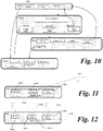
- FIG. 10 shows an expanded version of FIG. 8 illustrating the transitions between actions of the model 150 of FIG. 8 ;
- FIG. 11 shows an example of a model where a test description section comprises a plurality of model actions
- FIG. 12 shows the same example as FIG. 11 but where a single test description section is assigned to each action individually;
- FIG. 13 shows a flow chart in accordance with an embodiment of the present disclosure.
- FIG. 14 illustrates a flow chart of another aspect of the present disclosure.
- Test computer system
- FIG. 1 An example of a test computer system set-up suitable for use with the present disclosure is shown in FIG. 1 .
- Two SUTs 2 are in direct communication with the test computer system 6 , for example using infrared or Bluetooth communications, or over a local wired or wireless network, whilst two other SUTs are in communication with the test computer system 6 via the internet 26 .
- the test computer device/system 6 may be any suitable computer device, system, collection of computing devices or collections of computing systems.
- the test computer system 6 may, in non-limiting examples, comprise any one or more of: one or more processors 28 ; one or more controller devices 30 ; one or more memory devices 32 ; one or more user input devices 36 ; one or more output devices 34 such as, but not limited to, a GUI; one or more communication devices such as a transmitter 38 and/or a receiver device 40 .
- any one or more of the processor 28 , controller 30 , receiver 40 , transmitter 38 , or memory 32 may be a physical, non-transitory, device or apparatus.
- the devices/apparatus may be electronic, opto-electronic or optical.
- the processor 28 may, in principle, be any suitable processing device such as, but not limited to, a microprocessor, an application-specific instruction-set processor, a graphics processing unit (GPU/VPU), a physics processing unit (PPU), a digital signal processor, a network processor, a front end processor.
- processors include, but are not limited to, an Intel® processor, an AMD® processor.
- the controller 30 may be any suitable controller including any one or more of a controller chip, a controller board, a mainframe controller, an external controller or any other suitable controller.
- the controller may be, for example, a micro-controller.
- the memory 32 may, in principle be any suitable memory including any one or more of: mechanical memory such as, but not limited to, magnetic tape drive, hard-drive, optical drive; volatile and non-volatile memory such as, but not limited to, RAM, DRAM, SRAM, SDRAM, T-RAM, Z-RAM, TTRAM, ROM, Mask ROM, PROM, EPROM, EEPROM, NVRAM.
- mechanical memory such as, but not limited to, magnetic tape drive, hard-drive, optical drive
- volatile and non-volatile memory such as, but not limited to, RAM, DRAM, SRAM, SDRAM, T-RAM, Z-RAM, TTRAM, ROM, Mask ROM, PROM, EPROM, EEPROM, NVRAM.
- the SUT 2 may be remote from the test computer system 6 .
- the term ‘remote’ is intended to mean that the computer system or device is physically separate to the test computer system 6 such that when the test computer system and remote computer system interact, one or more transmitter and receiver devices are used to send and receive data over one or more communication channels.
- the communication channel may be any suitable channel using any of electrical, electromagnetic or optical signals.
- the SUT 2 can be any computing system or device running one or more computer programs.
- FIG. 2 shows an example model of a hardware/software stack 8 for a SUT 2 .
- the test computer system 6 can control features or aspects of any of these layers by interacting with the SUT 2 .
- the SUT 2 in principle can include any one or more parts of the hardware/software stack 8 of the system being tested 2 , i.e. the hardware 10 , firmware 12 , device drivers 14 , operating system 16 , middleware 18 , applications 20 and data/config 22 .
- a SUT 2 will at least comprise hardware 10 and an operating system 16 .
- FIG. 2 is only an example of a hardware/software stack model 8 .
- Other models with further details and layers may also be used to define a SUT 2 .
- the term ‘computer program’ is taken to mean any of (but not necessarily limited to) an application program 20 , middleware 18 , an operating system 16 , firmware 12 or device drivers 14 or any other medium supporting executable program code.
- the term ‘hardware’ 10 is taken to mean any one or more of the collection of physical elements that constitutes a computer system/device such as, but not limited to, a processor, memory device, communication ports, input/output devices.
- the term ‘firmware’ 12 is taken to mean any persistent memory and the program code/data stored within it, such as but not limited to, an embedded system.
- the term ‘device drivers’ 14 is taken to mean the one or more programs that operate to control a particular type of device incorporated into or attached to the computer device/system.
- the term ‘operating system’ 16 is taken to mean the one or more pieces, often a collection, of software that manages computer hardware and provides common services for computer programs.
- the term ‘middleware’ 18 is taken to mean the computer software that provides services to software applications beyond those available from the operating system 16 .
- the term “applications” 20 is taken to mean the computer software that causes a computing device or system to perform tasks that are typically beyond the running of the computer itself.
- the term ‘data/config.’ 22 is taken to be any other information provided to the SUT 2 that can be used to affect its running or output, for example data input into the application program 20 .
- a SUT 2 may comprise a different physical device to another SUT 2 as shown in FIG. 1 .
- the SUTs may be different physical computing devices running the same application program 20 using the same or different application program 20 .
- a SUT 2 may differ from another SUT 2 simply by running a different operating system 16 and/or different version of one or more application programs 20 .
- a first SUT 2 may be a PC (i.e. the computer hardware) running an operating system 16 and a first version of an application program 20
- a second SUT 2 may be the same hardware 10 as the first SUT 2 , running the same type and version of the operating system 16 but running a second, updated version of the application program 20 .
- one SUT 2 may differ from another SUT 2 by virtue of any different hardware/software configuration. For example any change in any one or more of the layers in the stack 8 of FIG. 1 from hardware 10 to application program 20 , may give rise to a different SUT 2 .
- test computer device typically interacts with the SUT 2 , it does so using a test program that executes the test description 24 .
- the test program is hosted on the test computer system 6 .
- the description 24 when run (executed) by the test program, typically causes the SUT 2 to be controlled by the test computer system 6 .
- a line in the test description 24 run by the test program with the phrase “click button X” will cause button ‘X’ on the GUI 4 of the SUT 2 to be selected and the operation associated with the selection of that button to be started upon the SUT 2 .
- Test programs are known to test the functionality of a SUT within an arrangement such as the exemplary configuration of FIG. 1 .
- the test program is run upon a computing device or computing system that is remote from the SUT.
- the computer system running the test program is however in communication with the SUT so that the test program can interact with the SUT.
- the SUT may be, for example, a PC running an application software upon an operating system, for example, Windows®, Android® or iOS®.
- the test program may comprise a plurality of components.
- a first component may interact with the model 150 (described later).
- a second component may be operable to execute test descriptions (described later) to interact with the SUT.
- test program any suitable test program may be used with the present disclosure.
- the specific nature of the test program and its functionality is not material to the present disclosure.
- a number of non-limiting examples will be described below.
- the validation steps operate by identifying expected objects in a GUI image that relate to executable functions that the test description may wish to identify and interact with or indicate the status of the SUT. Once the expected image object has been identified in the GUI image, the test program description can move to the next step in the test.
- the identification of the expected image object is performed using image analysis.
- the image analysis searches the GUI image for the expected image object using an existing reference image that is similar or identical to an expected image object. When a match is found, the expected image object is identified.
- the test program may utilise one or more GUI 4 images received directly or indirectly from the SUT 2 .
- FIG. 3 shows an example of this.
- the GUI 4 images are “snapshots” of the output of the GUI 4 of the SUT 2 at a particular time.
- these snapshots are saved as a graphical image file, for example a bitmap, gif or jpeg file.
- the GUI 4 images may be a snapshot of the whole GUI 4 or one or more portions of the GUI 4 .
- GUI snapshots may be only portions of the GUI image that have changed since a previous GUI image was sent.
- the SUT 2 may send these GUI images to the test computer system 6 automatically upon an initial command to start sending the images. Additionally or alternatively the SUT 2 may send one or more GUI images upon a command sent from the test computer system 6 . Additionally or alternatively the SUT 2 may send one or more GUI images upon a command sent to the SUT 2 resulting from an instruction from the test program, and/or the test description 24 .
- test program may interact with the GUI of the SUT 2 using an “object based tool”.
- object based tool the test program may use unique identifiers of the various UI controls on the screen to interact with them via an API.
- test program may interact with the SUT 2 by calling APIs directly.
- SUT 2 was a web server, it may be tested by using the model to send various sequences of HTTP commands to a server.
- test programs suitable for use with the present disclosure will be readily apparent to the skilled person.
- FIG. 4 shows an example of a test description 24 run within a test program.
- the test description 24 comprises multiple lines of text, numbers or other symbols that are typically executed by the test program in a sequential manner.
- the term “test description” may also be termed a “test script” or an “automated test description”.
- the description 24 may be written in any suitable scripting language, for example SenseTalk®. Preferably the description is loadable onto a carrier device such as a disc, memory stick or any other suitable electronic data carrier.
- a test program is used to execute the test description 24 .
- the functionality required to execute the test description 24 may be hosted by an operating system or any other software or dedicated hardware, for example the test description 24 may be a standalone executable file itself
- the description 24 is applicable to any suitable form of test program. Therefore, whilst FIG. 4 relates to image-based testing methods, this is not to be taken as limiting.
- the description 24 may utilise any of the test program examples described above, and any test program approach may be used with the present disclosure.
- the test description 24 forms part of an “automated test”.
- the test description 24 is typically lines 62 of text or other characters that typically contain instructions, that when executed by the test program, cause the SUT 2 to perform particular operations or execute functions.
- An instruction in the description 24 can include one or more standard commands and/or one or more other pieces of information or data.
- the command “Typetext” may be followed by the words “This is a test”.
- the test program running the automated test would execute the standard command “Typetext” to cause the SUT 2 to type the words “This is a test” into a particular text entry box on the SUT GUI 4 .
- the test may be stored using one or more storage device or computer readable media as described herein.
- An application to be tested may be in the form of application software provided to the tester, or a technical specification for an application.
- the application 50 may comprise a plurality of interacting software elements, and/or may comprise an entire computing system such as a mobile phone, desktop computer or specialist hardware.
- Non-limiting examples of specialist hardware may include: an aircraft or drone flight control system; in-vehicle software/hardware functions; or specialist computing systems.
- FIG. 5 shows a non-limiting example of an application 50 to be tested which comprises a plurality of operational states 52 - 1 - 52 - n . Whilst six operational states are shown in FIG. 5 , this need not be so and n may take any appropriate number.
- Each of the operational states corresponds to a particular condition of the application.
- actions can be carried out particular to that operational state 52 as will be described below. Actions may lead to transitions between operational states 52 as will be described below.
- an operational state 52 may correspond to a particular page, screen, setting or configuration of an application.
- FIG. 7 shows a basic, high-level non-limiting example of an application 50 in the form of an internet banking application.
- State 52 - 1 comprises a login page, state 52 - 2 a home page, state 52 - 3 a “view accounts” page, state 52 - 4 a payment page and state 52 - 5 a settings page Each of these comprises a particular operational state 52 of the application 50 .
- Operations can be carried out which take the application 50 into a different state—for example, from the home page 52 - 2 , the “view accounts” action transitions the application to the “view accounts” operational state, or the “settings” action transitions the application to the “settings” operational state as will be described below.
- each operational state 52 of the application 50 under test has at least one valid action available in that operational state 52 .
- action is meant a feature of the application 50 that enables the user to interact with the application in some way, by entering data, selecting a button or link or other interaction with the application 50 or system under test in general.
- An action may comprise one or more operations and/or validations required to carry out and/or test a specific task.
- an action may comprise a higher-level “logical” interaction comprising a plurality of inputs or interactions with the SUT.
- An example may be a “login” action that comprises multiple inputs such as click, select, type etc.
- the “action” is a higher-level function which is operable to complete the “login” process, where the “login” process requires a number of discrete operations.
- a valid action is meant an action which is allowed to be executed in that particular state.
- Execution of an action 54 in a particular operational state 52 may carry out a specific operation within a particular operational state 52 and/or may cause the application 50 under test to move to a different operational state 52 having different available actions.
- Action 54 may be specific to a particular operational state (e.g. login details for usernames and passwords) or may be a global action (e.g. a “home” button or link present in every operational state and which executes the same process when selected).
- Each operational state 52 is, in general, linked by at least one action which causes the application to move from one operational state to another operational state. However, this need not be the case and in certain scenarios an application may remain in a single operational state 52 or may exist in a plurality of mutually exclusive operational states 52 .
- Actions may in general be grouped into two categories—actions 54 which relate to operations carried out on the application 50 in a particular state and actions 56 which transition the application 50 into another state. As will be described later, actions 56 which cause a change of operational state 52 may also carry out operations on the current operational state 52 of the SUT before transitioning the application 50 to a new operational state 52 .
- Actions 54 may comprise dialog boxes, data entry boxes, drop down menus or other features which, when interacted with, cause the application to remain in the same operational state 52 .
- An example from FIG. 6 would be the login actions in operational state 52 - 1 where username, password and security character information is to be entered. Entering of this information does not cause the state of the application to change unless the “proceed” button is selected.
- transition actions 56 comprise commands or controls which cause the application 50 to transition between operational states 52 .
- the “proceed” action will cause the login state 52 - 1 to transition to the home page operational state 52 - 2 provided login details have been provided.
- the “settings” and “view account” actions 56 cause the application 50 to change state to states 52 - 5 or 52 - 3 states respectively.
- the transitions between states 52 are identified by state changes 58 .
- the state changes 58 in FIG. 6 show the actions 56 in each state which, when executed, lead to transitions between the states 52 of the application 50 .
- transitions For example, the action 56 which, when executed, causes transition 58 between state 52 - 1 (login screen) and state 52 - 2 (home page) cannot be executed (i.e. is not a valid action) unless correct login information is provided. Further, selection of actions such as the home button whilst on the home page state 52 - 2 will result in the state 52 - 2 remaining the same, although a refresh of the state 52 - 2 may occur.
- actions are present in the main application 50 irrespective of the state of the application 50 .
- actions “settings” and “home” are available in all application states 52 apart from the login state 52 - 1 .
- the application 50 is an internet shopping application
- the present disclosure relates to a method of automated testing and to a method of developing a test description.
- the present disclosure utilises a high-level modelling approach which enables a tester to define a particular application (i.e. a computer program running on a computer system to be tested) or system (e.g. a computing system having one or more interacting software elements) in terms of a model comprising a number of pre-defined states, actions and parameters.
- the model is flexible enough to be used to define a state-machine model, a process model, an action model, and others.
- testing of applications would be carried out in one of two ways—either by a manual “flow approach” or by full model automation.
- flow approach a test description may be written which describes a particular path through specific operations of each operational state. The flow is designed by the tester. Various permutations of flow through the operational states of the application will be designed independently and tested.
- the flow approach has a number of disadvantages. Firstly, the flow approach becomes cumbersome quickly where variation within the flow paths is possible. Consider an example of a login screen having three operations—“enter username”, “enter password” and “click submit” which can occur in any order, resulting in six permutations of flow within those operations alone. However, particular operations could be performed multiple times, for example the username could be entered, and then changed. This leads to potentially infinite flow possibilities which simply cannot be adequately tested using a conventional flow path approach where individual test descriptions are crafted for each flow path permutation.
- the temporal flow through the available operations of each operational state of the model will be specified by the tester. This may cover general use scenarios but, because the flow of operations is specified by a human, the flow will often only include “logical” flows based on typical use profiles. For example, for a banking application, a logical flow may comprise “login”-“check balance”-“make payment”-“log out”. However, an arbitrary flow pattern may never be tested and so bugs or other defects in such operation flows may never be tested. For example, using the example of the banking application, an arbitrary flow may be “login”-“log out”-“login”-“settings”-“change password”-“payment”-“settings”-“change password”-“payment”-“home”. Such use cases may never be contemplated by a tester and so may not be tested. This creates the potential for errors and bugs in the software to remain unidentified.
- the present disclosure relates to a testing method and model which avoids the above problems.
- the method operates by defining a high-level, non-specific model of the application to be tested.
- FIG. 7 shows a general schematic view of a test system 100 comprising a model 150 according to an embodiment of the present disclosure.
- the model 150 comprises a plurality of states 152 .
- Some states 152 of the model 150 may correspond to operational states of the application 50 . However, this is not to be taken to be limiting and the model 150 may comprise states 152 which do not directly correspond to an operational state of the application 50 .
- a model state 152 may be required which is a start state from which the application is launched.
- the model 150 also comprises modelled actions 154 , 156 as will be described below.
- Modelled actions 154 , 156 comprise one or more operations which may be carried out within one or more states 152 . Whether an action 154 , 156 is executable in a given state is specified by a number of preconditions as described in detail below.
- the model of the present disclosure only defines actions which are not allowable (via precondition constraints as described below). Therefore, any actions which either have no preconditions or preconditions which are currently met in full in that state and at that point in the execution process are, thus, assumed by the model to be valid and selectable. This reduces the modelling overhead and results in more manageable models. This process also has benefits in terms of coverage and test execution because the model will traverse and executes paths through the various valid actions which may not have occurred to the tester.
- Actions broadly comprise three classes: actions 154 which perform operation(s) in the current state and do not change the state, actions 156 which cause a change of state, and global actions 154 which are selectable in any state.
- actions 154 which perform operation(s) in the current state and do not change the state
- actions 156 which cause a change of state
- global actions 154 which are selectable in any state.
- properties of any given action 154 , 156 are defined by the attributes of an action 154 , 156 as will be discussed below.
- the model 150 further comprises test description sections 170 .
- the test description sections 170 comprise segments or “snippets” of a test description that can be associated with one or more actions 154 , 156 and which are executed when an associated action 154 , 156 is selected.
- test system 100 further comprises a database 190 associated with the model 150 .
- the database 190 may store particular data or parameters relating to operation of the model 150 as will be described later. Additionally, the model 150 may, in non-limiting embodiments, modify or update data in the database 190 .
- the model 150 In operation, the model 150 generates a test run through the model states 152 by selecting executable actions which are available in a current state 152 of the model 150 . Any test description sections 170 associated with a selected action 154 , 156 are then executed to generate an executable test 192 . This will be described in detail below. The results of the executable test 192 may then be used to update the database 190 (and hence model 150 ) prior to a further executable test 192 .
- FIG. 8 shows a schematic high-level diagram of an exemplary real-world model 150 according to an embodiment of the present disclosure.
- the model of FIG. 8 is based on the application 50 illustrated in FIG. 6 . However, this is to be taken as non-limiting and the model may be based on any suitable application to be tested.
- the model 150 has a plurality of model states 152 - 1 - 152 - n .
- each model state 152 - 1 to 152 - n corresponds to and is representative of a respective operational state 52 - 1 - 52 - n of the application 50 under test as shown in FIG. 6 .
- the states of the model 150 are entirely application dependent and may be varied as appropriate. However, the states relate to specific properties of the application under test 50 or related states which may exist, for example, prior to launch of the application-under-test or after the application-under-test has been closed.
- Each state is modelled as comprising a set of model actions 154 , 156 that can be taken within that state.
- the model actions are representative of the actions 54 , 56 that can be taken in the corresponding operational state 52 of the application under test 50 .
- the present disclosure can overcome a number of disadvantages of known techniques described above.
- Each state 152 of the model 152 generally has at least one action 154 , 156 available in that state 152 .
- this is non-limiting and may not apply to all states—for example, a log out state which may result from the selection of a “close application” action may not have any valid actions available in that state.
- Execution of an action 154 in a particular operational state 152 may carry out a specific function within a particular operational state 152 and/or may cause the application 50 under test to move to a different operational state 152 having different actions or functions.
- Actions 154 may be specific to a particular operational state (e.g. login details for usernames and passwords) or may comprise global actions (e.g. a “home” button or link present in every operational state and which executes the same process when selected).
- Each modelled state 152 is modelled as comprising a series of actions 154 , 156 that can be taken within that state.
- Modelled actions 154 correspond to actions 54 which relate to operations carried out on the application 50 in a particular state and modelled actions 156 correspond to actions 56 in the application 50 which transition the application 50 into another state.
- the model 150 has a hardware-level modelled general state 152 - 6 which has non-application specific modelled actions 154 .
- the application 50 is running on a smartphone or tablet, the user may be able to perform some non-application specific actions which may affect the application 50 itself. These are modelled as general actions 154 .
- the general actions 154 may include, in non-limiting examples, changing the volume up or down, changing the brightness, selecting the home button so as to exit/renter the application, attaching or disconnecting headphones, viewing a global drop-down or swipe-up menu, receiving or making a call etc.
- These actions 154 whilst not specifically actions within the application 50 itself can have an effect on the operation of the application and it may be desired to test these actions as part of an automated test.
- the modelling of such actions 154 cannot be done with a conventional “flow” model as commonly found in automated testing environments.
- each modelled action 154 , 156 has a number of attributes associated therewith.
- a modelled action 154 , 156 may also be associated with one or more test description sections 170 .
- a modelled action 154 , 156 may comprise one or more of the following: associated data parameters 180 , action preconditions 182 , a weighting 184 and a coverage factor 186 .
- the data parameters 180 , action preconditions 182 and a weighting 184 may be defined by the tester.
- the coverage factor 186 is a parameter updated with each test run and dependent upon the results of previous test runs.
- Each action 154 , 156 may have a variable number of the above components as set out in Table 1 below:
- TABLE 1 Action feature Allowable number Parameters 180 0 or more Preconditions 182 0 or more Weighting 184 1 Coverage factor 186 1 State changes 188 0 or more Test description sections 170 0 or more
- modelled action 154 which does not cause a change of state
- modelled action 156 which causes a change of state
- global action 154 accessible in any state
- these actions 154 do not have any precondition 182 attributes associated with a particular state (i.e. they are selectable in any state 152 provided there are no action preconditions not yet met). This is described below.
- any given action 154 , 156 may comprise any suitable number of, and type of, attributes.
- an action 156 has a state change 188 attribute but may also have one or more parameter 180 attributes or preconditions 182 . Any suitable permutation of attributes is possible within the scope of the present disclosure.
- Data parameters 180 relate to a variable which can be input to the application under test 50 when the action 154 , 156 is executed.
- the nature of the input is specified by the tester.
- the data parameters 180 may comprise data values to be inputted or entered into particular windows or boxes in the respective modelled state 152 of the application under test 50 , for example a text entry into a dialog box.
- a parameter 180 is equivalent to a “variable” in a typical programming language. Therefore, a data parameter 180 is a named unit of data that may have different specific values during the execution of the test. There are three levels of parameters 180 :
- a parameter 180 may comprise any variable; for example, a number, a date, true/false, a string, etc.
- the valid values for a parameter may be defined in any suitable manner.
- a parameter 180 may be defined as either a range (e.g. 1 to 1000) or a set ⁇ 1, 5, 6, 7 ⁇ .
- a parameter 180 of “username” could be defined to be ⁇ “Antony”, “Jon”, “Giles” ⁇ or any other character string or numerical value.
- a number of operations can be performed on a parameter 180 by the model 150 . These are:
- a parameter 180 may also be used in a check, for example when a value is returned from a test description section 170 it may be checked within the model 150 to ensure that it is a specific expected value or within an expected range.
- Action preconditions 182 specify constraints on when a particular action 154 , 156 is allowed to be executed. Whilst only a subset of all actions 154 , 156 are generally available in any one state 152 , it may be the case that preconditions determine that only a subset of the actions 154 , 156 in any one state 152 are available in that state. Whether an action 154 , 156 is valid and available in any one state 152 is determined by the preconditions 182 .
- preconditions Two basic types of precondition may be set for a given action 154 , 156 : state preconditions and action preconditions.
- an action 154 , 156 may be defined as being only selectable in particular states (e.g. the action 154 , 156 may only be selectable if the action's predefined state is the current state 152 of the model 150 ).
- the action 154 , 156 is available in any state—i.e. it is a global action.
- An example of a global action may be the volume control example as described above.
- Action preconditions define that an action 154 , 156 may only be selectable if the action's preconditions are met.
- preconditions 182 for an action X may be expressed as “only select action X after action Y” or “only select action X if a state variable has value Z”. Therefore, preconditions of prior states of other actions 154 , 156 , parameters 180 or the requirement for the model 150 to be in a particular state 152 determine whether an action 154 , 156 can be selected.
- the model 150 as built comprises states 152 representative of the operational states 52 of the application 50 .
- states 152 representative of the operational states 52 of the application 50 .
- actions 154 , 156 are possible.
- Some actions are transition actions 156 which cause the model 150 to transition to another state 152 .
- states 152 will have multiple actions 154 , 156 available in that state 152 .
- certain actions are used more often than others. For example, in a mobile banking application, the “make transfer” action would be used much more regularly than the “help” or “settings” action. To reflect this, the “make transfer” action must be tested more thoroughly.
- FIG. 9 shows an expanded and reconfigured view of part of the model of FIG. 7 .
- state 152 - 3 In this state (which, in this example, represents the “accounts summary” operational state 52 of application 50 ), three actions 156 a (settings), 156 b (make payment), 156 c (home) are available. All actions 156 are transition actions and, when the model 150 is run to test the application 50 , will cause the application 50 to move from state 52 - 3 to another state 152 .
- a weighting 184 is assigned to each of the actions 154 , 156 .
- the probability of the model 150 selecting action 16 a , 156 b or 156 c in any given test iteration is defined by a weighting 184 .
- the weightings 184 may be based on typical use scenarios and may be set by the tester. In this example, it may be known that a user will typically use the home and “make payment” buttons much more frequently, and the settings option less frequently or rarely.
- the weightings 184 for the actions 156 a , 156 b and 156 c may be set to 10 for the settings and 100 for the home and make payment actions 156 b , 156 c .
- the model 150 traverses the operational states 152 and reaches state 152 - 3 of the example, it will be ten times less likely to select the settings action 156 a than either the home or make payment actions 156 b , 156 c.
- the weighting approach when taken alone, has a number of problems. Firstly, the chance of selection of a particular action in a particular state is statistically independent between test runs of the model 150 . Therefore, if a high weighting is applied to a particular action, a disproportionate number of test runs may select, for example, home action 156 b and leave the other options relatively untested. In this scenario, a number of pathways through the actions 154 , 156 of the model 150 may be executed a plurality of times whilst other pathways may not be executed at all. This results in poor coverage of the application 50 .
- the present disclosure utilises a further parameter in the form of a coverage factor 186 .
- the coverage factor 186 for each action 154 , 156 is a parameter which is changed or modified in some way in dependence upon the paths taken by previous iterations of the automated test using the model 150 .
- the coverage factor 186 for each modelled action 154 , 156 is a parameter which is modified in dependence upon previous runs of the model 150 .
- the model 150 of the present disclosure incorporates a feedback aspect which modifies the coverage factor 186 associated with each action 154 , 156 depending upon how many times that action 154 , 156 has been executed in previous runs of the test program.
- the coverage factor 186 is implemented by storing in the database 190 the number of times that any given action 154 , 156 has been executed. This value of the coverage factor 186 is then used as an input to the action selection algorithm of the model 150 .
- the coverage factor 186 for a given model action 150 is set at 0.
- the coverage factor 186 for the model actions 154 is updated accordingly. Exemplary and non-limiting mechanisms for implementing such a coverage factor 186 will be described below.
- the implementation of the coverage factor as a feedback mechanism to influence the subsequent selection of model actions based on the previous selection of model actions in a current automated test or previous automated tests may be done in a number of ways.
- the number of times a particular model action 154 , 156 is selected during the course of one or more automated tests is logged.
- the coverage factor 186 for a model action 154 , 156 having a single parameter 180 has a value based on the number of “hits” of that model action 154 , 156 .
- the coverage factor 186 may then be described as a coverage counter for that model action 154 , 156 .
- the coverage factor 186 of one model action 154 , 156 is compared to the coverage factors 186 of any other model actions 154 , 156 available to be selected in the current state 152 of the model 150 .
- the influence of the coverage factor 186 of a model action 154 , 156 in determining the subsequent selection of that model action 154 , 156 is dependent upon the relative value of the coverage factor 186 of that model action 154 , 156 relative to any other model actions 154 , 156 available for selection in the current model state 152 .
- model action A is selected. Once (or at the same time as) model action A is selected/executed, the coverage factor 186 for model action A is updated to 1 (or 100%).
- model actions B or C are more likely to be selected than model A.
- A is not excluded from selection because the selection of a model action 154 from a plurality of available model actions 154 is dependent upon other aspects (e.g. probabilities, weightings 184 or other random elements.
- the coverage factors 186 may remain at 100% indicating that complete coverage of A, B and C have been achieved.
- the coverage factor 186 may have any reasonable target value for the number of selections (or hits).
- the coverage factor 186 is then defined as hits/target value, with a maximum value of 1.0, since 100% coverage is the maximum possible in this implementation.
- the coverage factor for a group of model actions 154 , 156 is defined as set out in expression 1) below:
- i is the number of hits and n is the number of model actions 154 , 156 in a group.
- model actions 154 , 156 which may be, for example, related (e.g. a set of login actions) to be allocated a coverage value.
- Examples 1 and 2 above presented a simple, non-limiting example of the coverage factor 186 in use. However, in other non-limiting embodiments, more complex implementations may be used to provide further advantages.
- the coverage factor 186 is being used to influence the selection of model actions 154 .
- the coverage factor 18 may no longer be an influencing input into the selection algorithm of the model 150 . This may lead, in some examples, to certain possible pathways through the model 150 being excluded.
- the target value of the coverage factor 186 for each model action 154 , 156 in a group of model actions 154 , 156 is modified so that it is always one more than the minimum hit count for any of the model actions 154 , 156 in the group. For example, if the minimum value is 0, then the target is 1 and so on.
- Model action A has a coverage factor 186 based on a hit count of 3, model action B a hit count of 5, model action C a hit count of 7 and model action D a hit count of 3.
- a negative feedback implementation may, alternatively or additionally, be used.
- the most executed actions 154 , 156 in previous test runs may be iteratively assigned lower coverage factors 186 and/or the less executed actions 154 , 156 in previous test runs may be assigned relatively higher coverage factors 186 .
- the model 150 will adaptively reconfigure during subsequent test runs such that the less well tested pathways are selected more often on subsequent test runs.
- This approach ensures that, over a sufficient number of test runs, excellent coverage of an application 50 can be performed by the automated test sequences.
- the coverage factor 186 is entirely independent of the weighting 184 for each action 154 , 156 . This has advantages in that the weighting 184 for each action 154 , 156 may be determined on the basis of predicted usage patterns and is not affected by the coverage factor 186 . Therefore, in the present embodiment, this relationship between actions 154 , 156 is preserved whilst also providing for improved coverage through use of the coverage factor 186 .
- any suitable modification to the coverage factors 186 may be applied after one or more test runs.
- the coverage factors 186 may be modified with each test run, or may only be modified after a set number of test runs.
- the coverage factor 186 applied to model actions 154 , 156 may take the form of dependent or independent factors which are used to modify the coverage factors of each action based on some factor which has a dependence upon the number of times that action has been selected or not selected in previous test runs.
- adequate coverage could be implemented by utilising a coverage factor 186 for an action that has a threshold value. This could be achieved, for example, by providing a coverage factor for each action, and as counter which logs the number of times each action is traversed. Then, when the counter reaches a maximum or threshold value for an action 154 , 156 , the model 150 is forced to select a different action 154 , 156 .
- weightings themselves may be modified.
- particular constraints may be imposed on certain actions based on how many times those actions have been selected in previous test runs.
- the tester may add additional “hints” or modifications to particular pathways. This may be useful in situations where a particular pathway would, routinely, only be accessed in a non-standard way which does not fit with a general use scenario. These empirical modifications may be used as required by the tester.
- an “update password” option may be automatically triggered once every month on a banking or shopping application. It is not necessary to test this functionality routinely during a large number of test cycles. However, it may be necessary to test it at least once. Therefore, the tester may introduce a command which causes the model to test a particular action or path only once every 100 test runs.
- the use of feedback as set out in the present disclosure renders such dependencies easy to implement because the model 150 has visibility of the previous paths taken by the model and other details of previous test runs, in contrast to known testing configurations.
- model 150 could implement to enable accurate testing of the application 50 under test.
- an action 154 , 156 has multiple data parameters 180 associated therewith (i.e. in the case of input variables), a preferred mechanism is provided for inputting these variables in each action 154 , 156 .
- one or more coverage factors 186 could be applied to the selection of data parameters 180 within an action 154 , 156 .
- the model may select a username based a coverage factor (i.e. based on how many times a particular user name has been selected in previous tests).
- the use of intra-action coverage factors for parameters may also influence the coverage factor 186 for that model action 154 , 156 .
- the coverage factor for that model action 154 , 156 may only be 50% because only one of the two permutations of parameter 180 has been selected. Therefore, if model action A and C are selected once each, model action A may have a coverage factor of 0.5 (50%) whereas model action C (with only a single parameter 180 ) may have a coverage factor of 100%.
- model action B (currently unselected) will be most likely to be selected, with model action A next most likely having 50% and model action C the least likely having 100%.
- test description is, in general, written manually and comprises a sequence of particular operation/validation steps to be carried out on the application 50 to be tested.
- a test description may comprise any suitable type of script or program which interacts and/or analyses the application-under-test 50 .
- An operation may be, for example, an instruction to execute a particular command, type text into a text box, click on an icon or other symbol present on the application interface in a given state.
- a validation may then be operable to identify that the operation has executed successfully, through identification of an “expected image” as discussed above (for image-based testing programs) or via other means.
- test description 170 relatively small sections are associated with particular actions 154 , 156 .
- the use of the model 150 of the present disclosure enables appropriate use of sections of a test description 170 which enables the model 150 to call the appropriate sections of the test description 170 when required.
- a model 150 can be built quickly and easily and then associated with manually- or automatically-created test description sections which enable execution of the various operation(s) and/or validation(s) forming the relevant actions 154 , 156 .
- This approach allows a tester to define the actions 154 , 156 at different levels of granularity, depending upon the level of detail that the tester desires to be incorporated at any particular stage.
- a single test description section may be associated with a plurality of individual actions 154 , 156 that are to be treated, for the purposes of the model, as a single deterministic process. This has numerous benefits as will be described below.
- a login action may itself require several actions to complete. For example, a user may be required to enter a username, password, select a security character from a list of security characters and select “proceed”.
- This testing can be done by implementing each individual action 154 , 156 individually in the model 150 so as to enable this functionality to be rigorously tested. Nevertheless, it may be that, within the testing framework of a particular application, the tester is not concerned with the login screen and wishes to test the action of, for example, the homepage or settings page. Conventionally, the tester would still need to model all features of the login page to ensure that a full model can operate correctly. This is cumbersome and time consuming.
- FIGS. 11 and 12 show examples of the login screen.
- FIG. 11 shows modelled actions 154 a (username), 154 b (password), 154 c (security character) and 156 (transition action “proceed” which transitions to state 152 - 2 ).
- modelled actions 154 a (username), 154 b (password), 154 c (security character) and 156 (transition action “proceed”) are all associated with a single test description section 170 .
- This test description section 170 defines a single, linear flow through the modelled actions 154 a , 154 b , 154 c and 156 . Therefore, when called by the model 150 , test description section 170 is run and executes a single, predetermined sequence of the actions 154 a , 154 b , 154 c and 156 (which, themselves may comprise one or more operation/validation commands) to complete the login process on state 152 - 1 .
- the tester may then reuse particular test description sections 170 for similar actions 154 , 156 .
- the “login” page cannot be fully use tested but this may not be important for a large number of testing scenarios. For example, if an update to an application is required to be tested, the “login” state may be identical to the previous version of the application and so does not need to be tested.
- the tester can rapidly build a model which can focus on the aspects of the application 50 which need to be tested without utilising time and resources to re-test an aspect of the application which does not require it.
- the modelled actions 154 , 156 can be modelled independently as described below.
- FIG. 12 shows an alternative scenario where a tester wishes to test the functionality of the login page more thoroughly.
- each model action 154 a , 154 b , 154 c , 156 is assigned a respective test description section 170 a , 170 b , 170 c , 170 d . Therefore, the login state 152 - 1 can be tested more thoroughly within the model 150 , with the model 150 being operable to call individual actions 154 a , 154 b , 154 c , 156 in any specific order or combination to test the login process.
- the method of the present disclosure enables a tester to select the level of granularity for each state 152 or action 154 , 156 of an application 50 , so that rapid progress on the testing of the application 50 can be made without the burden and complexity of a full model or the limitations of a simple flow process.
- the model of the present disclosure therefore, enables actions to be defined for each state of the application at different levels of abstraction. Multiple actions for a state of an application may be assigned to a single test description section 170 as a single execution which executes a pre-designated path through those actions. Alternatively, the multiple actions may be defined individually, thereby enabling testing to occur within the action group. Finally, an action 154 , 156 may be associated with multiple test description sections 170 if required.
- a tester can choose whether to implement greater functionality in the model 150 itself (e.g. in the form of model actions 154 , 156 ) or in the relevant test description sections 170 .
- test description section 170 has significant advantages. For example, consider a model action 154 which comprises two operations on the SUT—enter text into a text box and select a “proceed” icon. If the “proceed” icon is generic to the SUT, the test description section 170 could be written for this generic action and associated with multiple model actions 154 . 156 . Thus, the tester need only write a single test description section 170 for this operation which can be associated with multiple model actions 154 , 156 even if those model actions include further operations.
- a further variation of this approach is where the model action 154 , 156 itself is assigned a coverage value in addition to the parameters 180 .
- selection of one parameter 180 as per the example above would result in a coverage factor of 66.6%, where out of three possible coverage values (one for the model action 154 , 156 being selected at all, and one each for the two variations of parameter 180 ) two are selected.
- a parameter 180 “username-entered” which may be true or false and indicates whether any text has been written into a ‘username’ text box on a login state 152 - 1 .
- This would, therefore, comprise a parameter 180 within the “login” state 152 - 1 .
- the parameter 180 would initially be set to “false” because the username field is initially empty.
- the action 154 “username” is selected, the relevant test description section 170 will be executed and the “username” text box will be filled.
- the parameter 180 “username entered” would then be set to “true”.
- the “username” parameter 180 could then be defined as a precondition 182 for the action 156 “proceed”. In other words, the action 156 “proceed” is only allowed if the “username” parameter 180 is “true”.
- an action-level parameter 180 “story” may be set to a random value between 1 and 10.
- FIG. 13 is a flow chart showing the process for creating an automated test description. It is to be noted that the example of FIG. 13 is exemplary and the steps of the method may be executed in any suitable order as would be apparent to the skilled person.
- Step 100 Define Application to Test
- an application 50 to be tested is provided.
- an application to be tested may be in the form of application software provided to the tester, or a technical specification for an application.
- the application 50 may comprise a plurality of interacting software elements, and/or may comprise an entire computing system such as a mobile phone, desktop computer or specialist hardware.
- Non-limiting examples of specialist hardware may include: an aircraft or drone flight control system; in-vehicle software/hardware functions; or specialist computing systems.
- step 102 the method proceeds to step 102 .
- Step 102 Define Model States
- step 102 the model 150 is provided and the states of the model are defined.
- the states 152 of the model 150 are defined based on the operational states 52 of the application 50 . However, this need not be explicitly the case and other model states 152 may be defined which are necessary to operation of the model 150 but which do not directly correspond to a state of the application 50 .
- step 104 the method progresses to step 104 .
- Step 104 Define Model Actions
- the model actions 154 , 156 are defined.
- Model actions 154 , 156 are defined in relation to the actions 54 , 56 of the application 50 .
- the modelled actions 154 , 156 are then assigned attributes, namely appropriate numbers of: associated data parameters 180 , action preconditions 182 , a weighting 184 and a coverage factor 186 as described above.
- the data parameters 180 , action preconditions 182 and a weighting 184 may be defined by the tester.
- the coverage factor 186 is a parameter updated with each test run and dependent upon the results of previous test runs.
- step 104 the method proceeds to step 106 .
- Step 106 Assign Test Description Sections
- test description sections 170 are assigned to each action 154 , 156 .
- a single test description section 170 may be assigned to multiple actions 154 , 156 such that the multiple actions 154 , 156 are executed in a deterministic manner.
- test description sections 170 have been assigned to the modelled actions 154 , 156 as required, the method proceeds to step 108 .
- Step 108 Finalise Model and Test Description Sections
- the model 150 is finalised and is ready for execution by an appropriate testing tool.
- a workflow to create the model described above may comprise:
- a method for performing an automated test using the model 150 will now be described with reference to FIG. 14 .
- the method is configured to cause a test computer system 6 to communicate with a system under test comprising one or more computer programs (such as application 50 ) executed on a computer device.
- FIG. 14 shows a flow chart of this method.
- Step 200 Initialise Model
- the application 50 under test can then be tested using an appropriate testing tool.
- the model 150 is configured such that, when executed, it will carry out various actions corresponding to specific operational states 52 of the application 50 .
- the method proceeds to step 202 .
- Step 202 Execute Test Run
- the model is executed using a testing tool.
- the test tool will traverse the model 150 by executing one or more available actions 154 , 156 .
- the test run proceeds as set out in the following steps 202 - 216 , starting with step 204 .
- Step 204 Enter Start State
- a state 152 is defined as a “start” state. Whenever a test run is executed, the model 152 will start a test run in the start state.
- the model 150 then proceeds to step 206 .
- Step 206 Available Action?
- step 206 it is determined whether there are any actions 154 , 156 to select in the current state 152 .
- An action 154 , 156 can only be selected if it is a) an action 154 , 156 available in the current state 152 and b) that all preconditions 182 for the action 154 , 156 have been met as required (i.e. the action 154 , 156 is a valid action for that state 152 ).
- Step 208 Select action to execute
- an action 154 , 156 is selected for execution. If there is a single valid action 154 , 156 available in the current state, then that action is executed.
- the action 154 , 156 is selected based on an algorithm comprising the weighting 184 and coverage factors 186 .
- the action 154 , 156 is selected from the pool of available actions using an algorithm based on the current “coverage” of each available action 154 , 156 (i.e. how many times this action and its parameters have already been used in this test execution and potentially a selected subset of previous test executions), the weight 184 of the available actions (i.e. it's relative importance as defined by the tester in the model) and, optionally, other random elements provided by the tester.
- step 210 the method proceeds to step 210 .
- Step 210 Execute Action
- the selected action 154 , 156 is executed.
- the relevant section(s) of test description 170 associated with that action 154 , 156 is/are executed.
- the relevant test description section 170 comprises a series of action/validation commands to test the response of the application 50 under test. This may include, for example, selection of a text box and the entering of a particular text string.
- test description section 170 may relate to one or more actions 154 , 156 .
- a single action 154 , 156 may comprise a plurality of data parameters 180 , from which a single data parameter 180 is to be selected for execution.
- the weighting and coverage factors may be utilised here to select one of the data parameters 180 for execution.
- test description section 170 selected in step 210 executes correctly, then the method proceeds to step 214 . If the test description section 170 selected in step 210 returns an error, then the method proceeds to step 212 .
- Step 212 Execution Fail
- step 212 the execution has failed and the test run stops.
- the method proceeds to step 214 where the database is updated and then to step 216 .
- Step 214 Update Database
- a database is updated with the results of the action execution. This includes whether the execution of the test description section 170 was successful or failed.
- the action 154 , 156 which was selected in step 208 and executed in step 210 is logged in the database.
- Any attributes of the executed action 154 , 156 are also updated.
- any parameters 180 of the action 154 , 156 may be updated (e.g. from “false” to “true”) and any associated constraints 182 may be correspondingly modified or updated.
- the model 150 of the present disclosure incorporates a feedback parameter which modifies the coverage factor for each action 154 , 156 depending upon which action 154 , 156 was executed in step 210 .
- the coverage factor 186 for the selected action 154 , 156 and/or for non-selected actions 154 , 156 is then modified and an updated coverage factor 186 stored in the database. This approach ensures that, over a sufficient number of test runs, excellent coverage of an application 50 can be performed by the automated test sequences.
- the coverage factor for any intra-action data parameters 180 (i.e. coverage of available variables within actions 154 , 156 ) is also updated in this step.
- the logging of the pathway of selected actions 154 , 156 taken through the model 150 in any given test is also critical in application debugging. As for any test scenario, it is necessary to recreate that particular test run identically to debug the application 50 correctly. Therefore, by maintaining a record of the actions executed in a test run, together with the particular weights, coverage and constraints applied to those actions, then the “path” of selected actions can simply be repeated deterministically to debug the failed application 50 .
- step 216 The method then proceeds back to step 206 for execution of further actions or, if step 212 has been executed (i.e. test run fail), then the method proceeds to step 216 .
- Step 216 Finish
- test run finishes. The method may then proceed back to step 202 for further test run(s).
- step 214 is described as occurring after step 212 , this may not be the case. Step 214 may occur at any suitable point in a test run cycle.
- the pathway through each selected action 154 , 156 in a given test run could be determined for the whole test run. Then the test description sections 170 associated with the selected actions 154 , 156 could then be combined and run in a single deterministic sequence. The process would repeat for further test runs.
- model 150 and test data may be stored upon an external memory/storage device that is remote from the test computer system.
- the external device may be a central server or other computer system with access to one or more communication devices such that one or multiple test computer systems can send or retrieve data to/from the server.
- the server may operate one or more databases or other information handling systems on one or more memory devices.
- the databases may store multiple models or databases.
- One database, or a part of one or more databases, may be available to all test computer systems or a set of one or more test computer systems to enable data sharing between models.
- the methods described herein may be embodied in one or more pieces of software.
- the software is preferably held or otherwise encoded upon a memory device such as, but not limited to, any one or more of, a hard disk drive, RAM, ROM, solid state memory or other suitable memory device or component configured to software.
- the methods may be realised by executing/running the software. Additionally or alternatively, the methods may be hardware encoded.
- the method encoded in software or hardware is preferably executed using one or more processors.
- the memory and/or hardware and/or processors are preferably comprised as, at least part of, one or more servers and/or other suitable computing systems.
- the feedback element of the model 150 may be implemented in a conventional test description without use of a model.
- model 150 may be implemented without feedback elements and, in embodiments, may utilise the action group approach without modifying the various weightings of state changes based on the results of previous tests.
Abstract
Description
-
- username->username
- username->password
- username->proceed
- username->security character
- password->username
- password->password
- password->security character
- password->proceed
- security character (sc)->sc
- sc->username
- sc->password
- sc->proceed
| TABLE 1 | |||
| Action feature | | ||
| Parameters | |||
| 180 | 0 or | ||
| Preconditions | |||
| 182 | 0 or | ||
| Weighting | |||
| 184 | 1 | ||
| |
1 | ||
| State changes 188 | 0 or more | ||
| |
0 or more | ||
-
- 1) Global parameters (parameters accessible from all
actions 154, 156) - 2) State parameters (parameters accessible from all
actions - 3) Action parameters (parameters only accessible from within that
action 154, 156)
- 1) Global parameters (parameters accessible from all
-
- 4)
Set parameter 180 to a specific value; - 5) Set the
parameter 180 to a randomly value chosen from a set defined by the tester; - 6) Pass the
parameter 180 to atest description section 170; - 7) Take a value returned from a
test description section 170 and assign it to aparameter 180; and - 8) Use the parameter as part of a precondition 182 (described below).
- 4)
-
- Example 3 relates to a more complex mechanism known as “tidal” coverage. This non-limiting implementation provides, in use, a “moving target” for the
coverage factor 186 which encourages test complexity.
- Example 3 relates to a more complex mechanism known as “tidal” coverage. This non-limiting implementation provides, in use, a “moving target” for the
-
- 1. Define state A (step 102).
- 2. Define the actions for state A (step 104).
- 3. Assign
test description sections 170 to one or more actions (step 106). - 4. Define state B (step 102).
- 5. Define the actions for state B (step 104).
- 6. Update the actions for state A (step 104).
Method for Performing an Automated Test
Claims (19)
Priority Applications (1)
| Application Number | Priority Date | Filing Date | Title |
|---|---|---|---|
| US17/081,965 US11507496B2 (en) | 2016-02-10 | 2020-10-27 | Method of, and apparatus for, testing computer hardware and software |
Applications Claiming Priority (5)
| Application Number | Priority Date | Filing Date | Title |
|---|---|---|---|
| GB1602421.8A GB2547220A (en) | 2016-02-10 | 2016-02-10 | Method of, and apparatus for, testing computer hardware and software |
| GB1602421 | 2016-02-10 | ||
| GB1602421.8 | 2016-02-10 | ||
| US15/429,391 US10853229B2 (en) | 2016-02-10 | 2017-02-10 | Method of, and apparatus for, testing computer hardware and software |
| US17/081,965 US11507496B2 (en) | 2016-02-10 | 2020-10-27 | Method of, and apparatus for, testing computer hardware and software |
Related Parent Applications (1)
| Application Number | Title | Priority Date | Filing Date |
|---|---|---|---|
| US15/429,391 Continuation US10853229B2 (en) | 2016-02-10 | 2017-02-10 | Method of, and apparatus for, testing computer hardware and software |
Publications (2)
| Publication Number | Publication Date |
|---|---|
| US20210042215A1 US20210042215A1 (en) | 2021-02-11 |
| US11507496B2 true US11507496B2 (en) | 2022-11-22 |
Family
ID=55642124
Family Applications (2)
| Application Number | Title | Priority Date | Filing Date |
|---|---|---|---|
| US15/429,391 Active 2037-10-04 US10853229B2 (en) | 2016-02-10 | 2017-02-10 | Method of, and apparatus for, testing computer hardware and software |
| US17/081,965 Active US11507496B2 (en) | 2016-02-10 | 2020-10-27 | Method of, and apparatus for, testing computer hardware and software |
Family Applications Before (1)
| Application Number | Title | Priority Date | Filing Date |
|---|---|---|---|
| US15/429,391 Active 2037-10-04 US10853229B2 (en) | 2016-02-10 | 2017-02-10 | Method of, and apparatus for, testing computer hardware and software |
Country Status (2)
| Country | Link |
|---|---|
| US (2) | US10853229B2 (en) |
| GB (1) | GB2547220A (en) |
Cited By (2)
| Publication number | Priority date | Publication date | Assignee | Title |
|---|---|---|---|---|
| US20220382665A1 (en) * | 2021-05-28 | 2022-12-01 | International Business Machines Corporation | Model-based biased random system test through rest api |
| US11928051B2 (en) | 2021-05-28 | 2024-03-12 | International Business Machines Corporation | Test space sampling for model-based biased random system test through rest API |
Families Citing this family (5)
| Publication number | Priority date | Publication date | Assignee | Title |
|---|---|---|---|---|
| US20190188122A1 (en) * | 2017-12-20 | 2019-06-20 | Rainforest Qa, Inc. | Electronic product testing systems |
| GB2547222A (en) | 2016-02-10 | 2017-08-16 | Testplant Europe Ltd | Method of, and apparatus for, testing computer hardware and software |
| CN110711034A (en) * | 2016-11-08 | 2020-01-21 | 欧普帝姆斯特许股份公司 | Integrated operating room sterilization system-design and assembly |
| US10635573B2 (en) * | 2018-05-15 | 2020-04-28 | Sap Se | Auto-generated multiple input variants |
| US11069420B2 (en) | 2019-07-25 | 2021-07-20 | Micron Technology, Inc. | In-system test of a memory device |
Citations (156)
| Publication number | Priority date | Publication date | Assignee | Title |
|---|---|---|---|---|
| US3055015A (en) | 1960-07-25 | 1962-09-25 | Melvin H Silverman | Releasable hinge assembly |
| US4116444A (en) | 1976-07-16 | 1978-09-26 | Atari, Inc. | Method for generating a plurality of moving objects on a video display screen |
| US4791476A (en) | 1986-07-18 | 1988-12-13 | Texas Instruments Incorporated | Device for the composition of color component signals from luminance and chrominance signals and video display device comprising the application thereof |
| US4949248A (en) | 1988-07-15 | 1990-08-14 | Caro Marshall A | System for shared remote access of multiple application programs executing in one or more computers |
| US5022028A (en) | 1988-03-30 | 1991-06-04 | Elverex Limited | Software verification apparatus |
| US5066902A (en) | 1988-07-01 | 1991-11-19 | Fanuc Ltd | Automatic nominal data setting method in a visual sensor system |
| US5130936A (en) | 1990-09-14 | 1992-07-14 | Arinc Research Corporation | Method and apparatus for diagnostic testing including a neural network for determining testing sufficiency |
| US5134697A (en) | 1987-11-16 | 1992-07-28 | Prime Computer | Remote memory-mapped display with interactivity determination |
| US5157782A (en) | 1990-01-31 | 1992-10-20 | Hewlett-Packard Company | System and method for testing computer hardware and software |
| US5241625A (en) | 1990-11-27 | 1993-08-31 | Farallon Computing, Inc. | Screen image sharing among heterogeneous computers |
| US5249270A (en) | 1991-03-29 | 1993-09-28 | Echelon Corporation | Development system protocol |
| WO1994011818A1 (en) | 1992-11-19 | 1994-05-26 | Segue Software, Inc. | Automated gui interface testing |
| US5321838A (en) | 1991-02-28 | 1994-06-14 | Hensley Billy W | Event capturing for computer software evaluation |
| US5325377A (en) | 1990-01-31 | 1994-06-28 | Hewlett-Packard Company | Visual display signal processing system and method |
| US5333302A (en) | 1991-02-28 | 1994-07-26 | Hensley Billy W | Filtering event capture data for computer software evaluation |
| US5335342A (en) | 1991-05-31 | 1994-08-02 | Tiburon Systems, Inc. | Automated software testing system |
| US5343409A (en) | 1991-08-29 | 1994-08-30 | Hewlett-Packard Company | System and method for probing object resources in a window server environment |
| US5371883A (en) | 1993-03-26 | 1994-12-06 | International Business Machines Corporation | Method of testing programs in a distributed environment |
| US5475843A (en) | 1992-11-02 | 1995-12-12 | Borland International, Inc. | System and methods for improved program testing |
| US5499108A (en) | 1992-07-29 | 1996-03-12 | Visioneer Communications, Inc. | Document-driven scanning input device communicating with a computer |
| US5572444A (en) | 1992-08-19 | 1996-11-05 | Mtl Systems, Inc. | Method and apparatus for automatic performance evaluation of electronic display devices |
| US5591956A (en) | 1995-05-15 | 1997-01-07 | Welch Allyn, Inc. | Two dimensional data encoding structure and symbology for use with optical readers |
| US5594892A (en) | 1993-12-22 | 1997-01-14 | International Business Machines Corporation | Method for automated software application testing |
| US5598521A (en) | 1992-06-16 | 1997-01-28 | Honeywell Inc. | Directly connected display of process control system in an open systems windows environment |
| US5604509A (en) | 1995-04-14 | 1997-02-18 | Advent Design, Inc. | Remote display monitor system |
| US5634002A (en) | 1995-05-31 | 1997-05-27 | Sun Microsystems, Inc. | Method and system for testing graphical user interface programs |
| US5637851A (en) | 1989-03-01 | 1997-06-10 | Symbol Technologies, Inc. | Laser scanner for reading two dimensional bar codes |
| US5646602A (en) | 1991-10-29 | 1997-07-08 | Audio Authority Corporation | Switching network for selective product demonstration |
| US5669000A (en) | 1991-11-20 | 1997-09-16 | Apple Computer, Inc. | Interpreter for performing remote testing of computer systems |
| US5675141A (en) | 1995-02-03 | 1997-10-07 | Hitachi Denshi Kabushiki Kaisha | Method and apparatus for automatically detecting focusing point and image processing method and apparatus using the same |
| US5699263A (en) | 1994-08-25 | 1997-12-16 | Fujitsu Limited | Testing device for warning the possibility of illegal intercept of image information from an electromagnetic emission of a computer system |
| US5732212A (en) | 1992-10-23 | 1998-03-24 | Fox Network Systems, Inc. | System and method for remote monitoring and operation of personal computers |
| US5739809A (en) | 1994-06-27 | 1998-04-14 | Radius Inc. | Method and apparatus for display calibration and control |
| US5778230A (en) | 1995-11-13 | 1998-07-07 | Object Technology Licensing Corp. | Goal directed object-oriented debugging system |
| US5790977A (en) | 1997-02-06 | 1998-08-04 | Hewlett-Packard Company | Data acquisition from a remote instrument via the internet |
| US5796566A (en) | 1996-08-16 | 1998-08-18 | Compaq Computer Corporation | Printed circuit board having conductors which can be decoupled for isolating inactive integrated circuits connected thereto |
| US5805442A (en) | 1996-05-30 | 1998-09-08 | Control Technology Corporation | Distributed interface architecture for programmable industrial control systems |
| US5816820A (en) | 1996-09-18 | 1998-10-06 | Kelly Properties, Inc. | Simulation generation system |
| US5826239A (en) | 1996-12-17 | 1998-10-20 | Hewlett-Packard Company | Distributed workflow resource management system and method |
| US5831639A (en) | 1995-07-05 | 1998-11-03 | Symantec Corporation | Scanning display driver |
| US5848427A (en) | 1995-09-14 | 1998-12-08 | Fujitsu Limited | Information changing system and method of sending information over a network to automatically change information output on a user terminal |
| US5874966A (en) | 1995-10-30 | 1999-02-23 | International Business Machines Corporation | Customizable graphical user interface that automatically identifies major objects in a user-selected digitized color image and permits data to be associated with the major objects |
| US5881230A (en) | 1996-06-24 | 1999-03-09 | Microsoft Corporation | Method and system for remote automation of object oriented applications |
| US5889994A (en) | 1997-03-27 | 1999-03-30 | Hewlett-Packard, Co. | Method for cataloging graphics primitives by rendering state |
| US5898419A (en) | 1995-05-03 | 1999-04-27 | International Business Machines Corp. | Method and apparatus for scaling a cursor on local computer to have the same size relative to a window on the local computer as another cursor has to another window on a remote computer |
| US5926638A (en) | 1996-01-17 | 1999-07-20 | Nec Corporation | Program debugging system for debugging a program having graphical user interface |
| WO1999054820A1 (en) | 1998-04-22 | 1999-10-28 | Scientific Learning Corp. | Simulated play of interactive multimedia applications for error detection |
| US5982392A (en) | 1996-09-24 | 1999-11-09 | International Business Machines Corporation | Replicating and refreshing graphic images on a remote workstation |
| US5990852A (en) | 1996-10-31 | 1999-11-23 | Fujitsu Limited | Display screen duplication system and method |
| US5995663A (en) | 1994-01-18 | 1999-11-30 | Matsushita Electric Industrial Co., Ltd. | Shape detection apparatus |
| US6002871A (en) | 1997-10-27 | 1999-12-14 | Unisys Corporation | Multi-user application program testing tool |
| US6005964A (en) | 1996-01-24 | 1999-12-21 | The Board Of Trustees Of The University Of Illinois | Automatic machine vision microscope slide inspection system and method |
| US6011830A (en) * | 1996-12-10 | 2000-01-04 | Telefonaktiebolaget Lm Ericsson | Operational test device and method of performing an operational test for a system under test |
| US6014125A (en) | 1994-12-08 | 2000-01-11 | Hyundai Electronics America | Image processing apparatus including horizontal and vertical scaling for a computer display |
| US6023580A (en) | 1996-07-03 | 2000-02-08 | Objectswitch Corporation | Apparatus and method for testing computer systems |
| US6026236A (en) | 1995-03-08 | 2000-02-15 | International Business Machines Corporation | System and method for enabling software monitoring in a computer system |
| US6037926A (en) | 1994-11-18 | 2000-03-14 | Thomson Consumer Electronics, Inc. | Emulation of computer monitor in a wide screen television |
| US6046740A (en) | 1997-02-07 | 2000-04-04 | Seque Software, Inc. | Application testing with virtual object recognition |
| WO2000019320A1 (en) | 1998-09-30 | 2000-04-06 | Netscout Service Level Corporation | Evaluating computer resources by end-user emulation |
| US6067638A (en) | 1998-04-22 | 2000-05-23 | Scientific Learning Corp. | Simulated play of interactive multimedia applications for error detection |
| US6118447A (en) | 1996-12-03 | 2000-09-12 | Ergolight Ltd. | Apparatus and methods for analyzing software systems |
| US6119247A (en) | 1998-06-22 | 2000-09-12 | International Business Machines Corporation | Remote debugging of internet applications |
| US6195765B1 (en) | 1998-01-05 | 2001-02-27 | Electronic Data Systems Corporation | System and method for testing an application program |
| US6226407B1 (en) | 1998-03-18 | 2001-05-01 | Microsoft Corporation | Method and apparatus for analyzing computer screens |
| US20010002697A1 (en) | 1996-03-29 | 2001-06-07 | Takashi Hiroi | Electron beam inspection method and apparatus and semiconductor manufacturing method and its manufacturing line utilizing the same |
| US6249882B1 (en) | 1998-06-15 | 2001-06-19 | Hewlett-Packard Company | Methods and systems for automated software testing |
| US6282701B1 (en) | 1997-07-31 | 2001-08-28 | Mutek Solutions, Ltd. | System and method for monitoring and analyzing the execution of computer programs |
| US6292171B1 (en) | 1999-03-31 | 2001-09-18 | Seiko Epson Corporation | Method and apparatus for calibrating a computer-generated projected image |
| US20010022861A1 (en) | 2000-02-22 | 2001-09-20 | Kazunori Hiramatsu | System and method of pointed position detection, presentation system, and program |
| US6295515B1 (en) | 1997-11-03 | 2001-09-25 | Lucent Technologies Inc. | Static partial order reduction |
| US6317223B1 (en) | 1998-12-14 | 2001-11-13 | Eastman Kodak Company | Image processing system for reducing vertically disposed patterns on images produced by scanning |
| US6331855B1 (en) | 1999-04-28 | 2001-12-18 | Expertcity.Com, Inc. | Method and apparatus for providing remote access, control of remote systems and updating of display information |
| US20010055415A1 (en) | 1999-12-16 | 2001-12-27 | Nec Corporation | Pattern inspection method and pattern inspection device |
| US6353897B1 (en) | 1999-01-06 | 2002-03-05 | International Business Machines Corporation | Object oriented apparatus and method for testing object oriented software |
| US20020029259A1 (en) | 2000-07-26 | 2002-03-07 | Nec Corporation | Remote operation system and remote operation method thereof |
| US6356931B2 (en) | 1997-10-06 | 2002-03-12 | Sun Microsystems, Inc. | Method and system for remotely browsing objects |
| US20020039436A1 (en) | 1990-11-16 | 2002-04-04 | David Alumot | Optical inspection apparatus for defect detection |
| US6370589B1 (en) | 1992-10-15 | 2002-04-09 | Siemens Aktiengesellschaft | Process for performing at least one test on at least one of the objects of an object-oriented program capable of running in parallel on a computer |
| US20020056075A1 (en) | 2000-11-06 | 2002-05-09 | Andrew Hamilton | System for a run-time engine capable for pager capable remote device |
| US20020054104A1 (en) | 1998-11-03 | 2002-05-09 | Stephen C. Berczik | Anticipatory processing for a graphical user interface |
| US20020099978A1 (en) | 2001-01-25 | 2002-07-25 | Kraffert Mark J. | Capturing fields from an output of a software application |
| US20020100014A1 (en) | 2000-04-04 | 2002-07-25 | Jose Iborra | Automatic software production system |
| US20020101519A1 (en) | 2001-01-29 | 2002-08-01 | Myers Jeffrey S. | Automatic generation of information identifying an object in a photographic image |
| US20020111813A1 (en) | 2001-02-13 | 2002-08-15 | Capps Stephan P. | System and method for providing a universal and automatic communication access point |
| US20020141641A1 (en) | 2001-03-27 | 2002-10-03 | Ncr Corporation | Methods and apparatus for locating and identifying text labels in digital images |
| US6466329B1 (en) | 1997-03-28 | 2002-10-15 | International Business Machines Corporation | Method and apparatus for managing copy quality in the hardcopy or softcopy reproduction of either original pages or extrinsically received electronic page images |
| US20020152169A1 (en) | 2001-04-12 | 2002-10-17 | Rabindranath Dutta | Method and apparatus for facilitating transactions at an automatic teller machine |
| US6470346B2 (en) | 1998-10-07 | 2002-10-22 | Millennium Pharmaceuticals, Inc. | Remote computation framework |
| US6476858B1 (en) | 1999-08-12 | 2002-11-05 | Innovation Institute | Video monitoring and security system |
| US6502045B1 (en) | 1999-05-19 | 2002-12-31 | Ics Systems, Inc. | Unified analog/digital waveform software analysis tool with video and audio signal analysis methods |
| US20030012414A1 (en) | 2001-06-29 | 2003-01-16 | Huitao Luo | Automatic digital image enhancement |
| US20030020751A1 (en) | 2001-07-03 | 2003-01-30 | Laurent Safa | Observation display method for dynamically changing on monitor screen object information observed on computer network and observation display system using computer network |
| US20030026457A1 (en) | 2001-08-06 | 2003-02-06 | Mitutoyo Corporation | Systems and methods for correlating images in an image correlation system with reduced computational loads |
| US20030053675A1 (en) | 2001-09-14 | 2003-03-20 | Masayuki Kuwabara | Pattern inspection method and inspection apparatus |
| US20030056150A1 (en) | 2001-09-14 | 2003-03-20 | David Dubovsky | Environment based data driven automated test engine for GUI applications |
| US20030058277A1 (en) | 1999-08-31 | 2003-03-27 | Bowman-Amuah Michel K. | A view configurer in a presentation services patterns enviroment |
| US20030065654A1 (en) | 2001-09-28 | 2003-04-03 | Yasuhisa Ikushima | Pattern matching method using a pyramid structure search, image detecting device, and computer-readable medium |
| US20030066031A1 (en) | 2001-09-28 | 2003-04-03 | Siebel Systems, Inc. | Method and system for supporting user navigation in a browser environment |
| US20030071908A1 (en) | 2001-09-18 | 2003-04-17 | Masato Sannoh | Image pickup device, automatic focusing method, automatic exposure method, electronic flash control method and computer program |
| US20030115595A1 (en) | 2001-12-13 | 2003-06-19 | Stevens John Herbert | System and method for automatic switching to interactive application during television program breaks |
| US20030123733A1 (en) | 2001-12-28 | 2003-07-03 | Keskar Dhananjay V. | Recognizing commands written onto a medium |
| US20030139918A1 (en) | 2000-06-06 | 2003-07-24 | Microsoft Corporation | Evaluating hardware models having resource contention |
| US6606115B1 (en) | 1998-04-18 | 2003-08-12 | Flir Systems Boston | Method and apparatus for monitoring the thermal characteristics of an image |
| US20030153823A1 (en) | 1998-08-25 | 2003-08-14 | Geiser Edward A. | Method for automated analysis of apical four-chamber images of the heart |
| US20030185431A1 (en) | 2002-03-29 | 2003-10-02 | Hong Dezhong | Method and system for golden template image extraction |
| US20030198385A1 (en) | 2000-03-10 | 2003-10-23 | Tanner Cameron W. | Method apparatus for image analysis |
| US20030204626A1 (en) | 2002-04-24 | 2003-10-30 | Microsoft Corporation | Method and apparatus for efficiently matching responses to requests previously passed by a network node |
| US20040017513A1 (en) | 2002-07-22 | 2004-01-29 | Naomasa Takahashi | Electronic equipment, server, and presentation method of layout script text |
| US20040044514A1 (en) | 2002-09-04 | 2004-03-04 | Granny Nicola V. | Polymorphic computational system and method in signals intelligence analysis |
| US20040049530A1 (en) | 2001-06-11 | 2004-03-11 | Simon Lok | Distributed computer system using a graphical user interface toolkit |
| US6708217B1 (en) | 2000-01-05 | 2004-03-16 | International Business Machines Corporation | Method and system for receiving and demultiplexing multi-modal document content |
| US6710790B1 (en) | 1998-08-13 | 2004-03-23 | Symantec Corporation | Methods and apparatus for tracking the active window of a host computer in a remote computer display window |
| US20040076323A1 (en) | 2002-08-06 | 2004-04-22 | Omron Corporation | Inspection data producing method and board inspection apparatus using the method |
| US20040081341A1 (en) | 2002-07-18 | 2004-04-29 | Dieter Cherek | Method and arrangement for positioning a patient in a medical diagnosis or therapy device |
| US6772107B1 (en) | 1999-11-08 | 2004-08-03 | J.D. Edwards World Source Company | System and method for simulating activity on a computer network |
| US20040181754A1 (en) | 2003-03-12 | 2004-09-16 | Kremer Karl Heinz | Manual and automatic alignment of pages |
| US20040201709A1 (en) | 2001-06-26 | 2004-10-14 | Eastman Kodak Company | Electronic camera and system for transmitting digital over a communication network |
| US20040255276A1 (en) | 2003-06-16 | 2004-12-16 | Gene Rovang | Method and system for remote software testing |
| US20040260993A1 (en) | 2003-06-18 | 2004-12-23 | Griffin Timothy Alan | Method, system, and program for simulating Input/Output (I/O) requests to test a system |
| US20050008212A1 (en) | 2003-04-09 | 2005-01-13 | Ewing William R. | Spot finding algorithm using image recognition software |
| US20050031165A1 (en) | 2003-08-08 | 2005-02-10 | Lockheed Martin Corporation. | Method and apparatus for tracking an object |
| US20050035877A1 (en) | 2003-08-11 | 2005-02-17 | Duk-Soo Kim | Automatic meter reading system and method for transmitting meter reading data in the same |
| US6867789B1 (en) | 2000-02-15 | 2005-03-15 | Bank One, Delaware, National Association | System and method for generating graphical user interfaces |
| US6904389B2 (en) | 2001-03-06 | 2005-06-07 | Hewlett-Packard Development Company, L.P. | Remote computer testing |
| US6907546B1 (en) | 2000-03-27 | 2005-06-14 | Accenture Llp | Language-driven interface for an automated testing framework |
| US6920509B1 (en) | 1999-09-28 | 2005-07-19 | Nec Corporation | Device information acquisition method, device controller, and bridge |
| US7046848B1 (en) | 2001-08-22 | 2006-05-16 | Olcott Peter L | Method and system for recognizing machine generated character glyphs and icons in graphic images |
| US20060228040A1 (en) | 2003-02-28 | 2006-10-12 | Simon Richard A | Method and system for enhancing portrait image that are processed in a batch mode |
| US7218795B2 (en) | 2001-07-06 | 2007-05-15 | Corel Corporation | Assisted scratch removal |
| US7222265B1 (en) | 2001-07-02 | 2007-05-22 | Lesuer Brian J | Automated software testing |
| US20070131877A9 (en) | 1999-11-29 | 2007-06-14 | Takashi Hiroi | Pattern inspection method and system therefor |
| US7241993B2 (en) | 2000-06-27 | 2007-07-10 | Ebara Corporation | Inspection system by charged particle beam and method of manufacturing devices using the system |
| US20070217687A1 (en) | 2002-06-28 | 2007-09-20 | Toshimichi Arima | Display control method, and program, information processing apparatus and optical character recognizer |
| US20070283327A1 (en) | 2006-06-02 | 2007-12-06 | Microsoft Corporation | Hierarchical test verification using an extendable interface |
| US20080195257A1 (en) | 2004-08-18 | 2008-08-14 | Jurgen Rauch | Guidance and Security System for Complex Transport Systems |
| US20090052750A1 (en) | 2003-06-26 | 2009-02-26 | Fotonation Vision Limited | Digital Image Processing Using Face Detection Information |
| US7683881B2 (en) | 2004-05-24 | 2010-03-23 | Keytec, Inc. | Visual input pointing device for interactive display system |
| US7769895B1 (en) | 2001-08-17 | 2010-08-03 | Corda Technologies, Inc. | System and method for ensuring that a web browser displays the highest ranked image format possible for an image |
| US20100197376A1 (en) | 2001-02-06 | 2010-08-05 | Kerr Michael A | System and method for streaming a lottery game |
| US7797409B1 (en) * | 2001-01-26 | 2010-09-14 | Sobha Renaissance Information Technology | System and method for managing a communication network utilizing state-based polling |
| US20110145653A1 (en) * | 2008-08-15 | 2011-06-16 | Verum Holding B.V. | Method and system for testing complex machine control software |
| US20110145643A1 (en) * | 2009-12-10 | 2011-06-16 | Microsoft Corporation | Reproducible test framework for randomized stress test |
| US8091132B2 (en) | 2006-03-03 | 2012-01-03 | New Jersey Institute Of Technology | Behavior-based traffic differentiation (BTD) for defending against distributed denial of service (DDoS) attacks |
| US20120047488A1 (en) | 2010-08-23 | 2012-02-23 | Micro Focus (Us), Inc. | State driven test editor |
| US20120180028A1 (en) * | 2011-01-11 | 2012-07-12 | Fujitsu Limited | Setting program, workflow creating method, and work flow creating apparatus |
| US8321894B2 (en) | 2002-06-21 | 2012-11-27 | Sony Corporation | Transmission apparatus, reception apparatus |
| US20130212054A1 (en) * | 2012-02-15 | 2013-08-15 | The Mathworks, Inc. | Generating a state diagram |
| US8610734B2 (en) | 1999-11-12 | 2013-12-17 | Hewlett-Packard Development Company, L.P. | Operating system independent method and apparatus for graphical remote access |
| US8671394B1 (en) * | 2003-11-26 | 2014-03-11 | The Mathworks, Inc. | Monitoring test steps in test environments |
| US20140208222A1 (en) | 2003-10-01 | 2014-07-24 | Testplant, Inc. | Method for monitoring a graphical user interface on a second computer display from a first computer |
| US8903688B1 (en) | 2005-03-31 | 2014-12-02 | The Mathworks, Inc. | Test entities for evaluation and validation of a model |
| US20150052095A1 (en) | 2013-08-15 | 2015-02-19 | Cisco Technology, Inc. | Model-based approach to intelligent automation in a computing domain |
| US20150106653A1 (en) | 2013-10-10 | 2015-04-16 | International Business Machines Corporation | Test selection based on domination criterion |
| US20160246287A1 (en) | 2014-03-13 | 2016-08-25 | Rolls-Royce Corporation | Probabilistic evaluation of turbomachinery design to predict high cycle fatigue failure |
| US10157612B2 (en) * | 2012-08-02 | 2018-12-18 | Nuance Communications, Inc. | Methods and apparatus for voice-enabling a web application |
| US10853226B2 (en) | 2016-02-10 | 2020-12-01 | Eggplant Limited | Method of, and apparatus for, testing computer hardware and software |
-
2016
- 2016-02-10 GB GB1602421.8A patent/GB2547220A/en not_active Withdrawn
-
2017
- 2017-02-10 US US15/429,391 patent/US10853229B2/en active Active
-
2020
- 2020-10-27 US US17/081,965 patent/US11507496B2/en active Active
Patent Citations (171)
| Publication number | Priority date | Publication date | Assignee | Title |
|---|---|---|---|---|
| US3055015A (en) | 1960-07-25 | 1962-09-25 | Melvin H Silverman | Releasable hinge assembly |
| US4116444A (en) | 1976-07-16 | 1978-09-26 | Atari, Inc. | Method for generating a plurality of moving objects on a video display screen |
| US4791476A (en) | 1986-07-18 | 1988-12-13 | Texas Instruments Incorporated | Device for the composition of color component signals from luminance and chrominance signals and video display device comprising the application thereof |
| US5134697A (en) | 1987-11-16 | 1992-07-28 | Prime Computer | Remote memory-mapped display with interactivity determination |
| US5022028A (en) | 1988-03-30 | 1991-06-04 | Elverex Limited | Software verification apparatus |
| US5066902A (en) | 1988-07-01 | 1991-11-19 | Fanuc Ltd | Automatic nominal data setting method in a visual sensor system |
| US4949248A (en) | 1988-07-15 | 1990-08-14 | Caro Marshall A | System for shared remote access of multiple application programs executing in one or more computers |
| US5637851A (en) | 1989-03-01 | 1997-06-10 | Symbol Technologies, Inc. | Laser scanner for reading two dimensional bar codes |
| US5157782A (en) | 1990-01-31 | 1992-10-20 | Hewlett-Packard Company | System and method for testing computer hardware and software |
| US5325377A (en) | 1990-01-31 | 1994-06-28 | Hewlett-Packard Company | Visual display signal processing system and method |
| US5130936A (en) | 1990-09-14 | 1992-07-14 | Arinc Research Corporation | Method and apparatus for diagnostic testing including a neural network for determining testing sufficiency |
| US20020039436A1 (en) | 1990-11-16 | 2002-04-04 | David Alumot | Optical inspection apparatus for defect detection |
| US20090148033A1 (en) | 1990-11-16 | 2009-06-11 | David Alumot | Optical inspection apparatus for substrate defect detection |
| US5241625A (en) | 1990-11-27 | 1993-08-31 | Farallon Computing, Inc. | Screen image sharing among heterogeneous computers |
| US5321838A (en) | 1991-02-28 | 1994-06-14 | Hensley Billy W | Event capturing for computer software evaluation |
| US5333302A (en) | 1991-02-28 | 1994-07-26 | Hensley Billy W | Filtering event capture data for computer software evaluation |
| US5249270A (en) | 1991-03-29 | 1993-09-28 | Echelon Corporation | Development system protocol |
| US5335342A (en) | 1991-05-31 | 1994-08-02 | Tiburon Systems, Inc. | Automated software testing system |
| US5343409A (en) | 1991-08-29 | 1994-08-30 | Hewlett-Packard Company | System and method for probing object resources in a window server environment |
| US5646602A (en) | 1991-10-29 | 1997-07-08 | Audio Authority Corporation | Switching network for selective product demonstration |
| US5669000A (en) | 1991-11-20 | 1997-09-16 | Apple Computer, Inc. | Interpreter for performing remote testing of computer systems |
| US5598521A (en) | 1992-06-16 | 1997-01-28 | Honeywell Inc. | Directly connected display of process control system in an open systems windows environment |
| US5499108C1 (en) | 1992-07-29 | 2001-01-16 | Primax Electronics Ltd | Document-driven scanning input device communicating with a computer |
| US5499108A (en) | 1992-07-29 | 1996-03-12 | Visioneer Communications, Inc. | Document-driven scanning input device communicating with a computer |
| US5572444A (en) | 1992-08-19 | 1996-11-05 | Mtl Systems, Inc. | Method and apparatus for automatic performance evaluation of electronic display devices |
| US6370589B1 (en) | 1992-10-15 | 2002-04-09 | Siemens Aktiengesellschaft | Process for performing at least one test on at least one of the objects of an object-oriented program capable of running in parallel on a computer |
| US5732212A (en) | 1992-10-23 | 1998-03-24 | Fox Network Systems, Inc. | System and method for remote monitoring and operation of personal computers |
| US5475843A (en) | 1992-11-02 | 1995-12-12 | Borland International, Inc. | System and methods for improved program testing |
| WO1994011818A1 (en) | 1992-11-19 | 1994-05-26 | Segue Software, Inc. | Automated gui interface testing |
| US5600789A (en) | 1992-11-19 | 1997-02-04 | Segue Software, Inc. | Automated GUI interface testing |
| US5781720A (en) | 1992-11-19 | 1998-07-14 | Segue Software, Inc. | Automated GUI interface testing |
| US5371883A (en) | 1993-03-26 | 1994-12-06 | International Business Machines Corporation | Method of testing programs in a distributed environment |
| US5594892A (en) | 1993-12-22 | 1997-01-14 | International Business Machines Corporation | Method for automated software application testing |
| US5995663A (en) | 1994-01-18 | 1999-11-30 | Matsushita Electric Industrial Co., Ltd. | Shape detection apparatus |
| US5739809A (en) | 1994-06-27 | 1998-04-14 | Radius Inc. | Method and apparatus for display calibration and control |
| US5699263A (en) | 1994-08-25 | 1997-12-16 | Fujitsu Limited | Testing device for warning the possibility of illegal intercept of image information from an electromagnetic emission of a computer system |
| US6037926A (en) | 1994-11-18 | 2000-03-14 | Thomson Consumer Electronics, Inc. | Emulation of computer monitor in a wide screen television |
| US6014125A (en) | 1994-12-08 | 2000-01-11 | Hyundai Electronics America | Image processing apparatus including horizontal and vertical scaling for a computer display |
| US5675141A (en) | 1995-02-03 | 1997-10-07 | Hitachi Denshi Kabushiki Kaisha | Method and apparatus for automatically detecting focusing point and image processing method and apparatus using the same |
| US6026236A (en) | 1995-03-08 | 2000-02-15 | International Business Machines Corporation | System and method for enabling software monitoring in a computer system |
| US5604509A (en) | 1995-04-14 | 1997-02-18 | Advent Design, Inc. | Remote display monitor system |
| US5898419A (en) | 1995-05-03 | 1999-04-27 | International Business Machines Corp. | Method and apparatus for scaling a cursor on local computer to have the same size relative to a window on the local computer as another cursor has to another window on a remote computer |
| US5591956A (en) | 1995-05-15 | 1997-01-07 | Welch Allyn, Inc. | Two dimensional data encoding structure and symbology for use with optical readers |
| US5634002A (en) | 1995-05-31 | 1997-05-27 | Sun Microsystems, Inc. | Method and system for testing graphical user interface programs |
| US5831639A (en) | 1995-07-05 | 1998-11-03 | Symantec Corporation | Scanning display driver |
| US5848427A (en) | 1995-09-14 | 1998-12-08 | Fujitsu Limited | Information changing system and method of sending information over a network to automatically change information output on a user terminal |
| US5874966A (en) | 1995-10-30 | 1999-02-23 | International Business Machines Corporation | Customizable graphical user interface that automatically identifies major objects in a user-selected digitized color image and permits data to be associated with the major objects |
| US5778230A (en) | 1995-11-13 | 1998-07-07 | Object Technology Licensing Corp. | Goal directed object-oriented debugging system |
| US5926638A (en) | 1996-01-17 | 1999-07-20 | Nec Corporation | Program debugging system for debugging a program having graphical user interface |
| US6005964A (en) | 1996-01-24 | 1999-12-21 | The Board Of Trustees Of The University Of Illinois | Automatic machine vision microscope slide inspection system and method |
| US20010002697A1 (en) | 1996-03-29 | 2001-06-07 | Takashi Hiroi | Electron beam inspection method and apparatus and semiconductor manufacturing method and its manufacturing line utilizing the same |
| US20050082476A1 (en) | 1996-03-29 | 2005-04-21 | Takashi Hiroi | Electron beam inspection method and apparatus and semiconductor manufacturing method and its manufacturing line utilizing the same |
| US5805442A (en) | 1996-05-30 | 1998-09-08 | Control Technology Corporation | Distributed interface architecture for programmable industrial control systems |
| US5881230A (en) | 1996-06-24 | 1999-03-09 | Microsoft Corporation | Method and system for remote automation of object oriented applications |
| US6023580A (en) | 1996-07-03 | 2000-02-08 | Objectswitch Corporation | Apparatus and method for testing computer systems |
| US5796566A (en) | 1996-08-16 | 1998-08-18 | Compaq Computer Corporation | Printed circuit board having conductors which can be decoupled for isolating inactive integrated circuits connected thereto |
| US5816820A (en) | 1996-09-18 | 1998-10-06 | Kelly Properties, Inc. | Simulation generation system |
| US5982392A (en) | 1996-09-24 | 1999-11-09 | International Business Machines Corporation | Replicating and refreshing graphic images on a remote workstation |
| US5990852A (en) | 1996-10-31 | 1999-11-23 | Fujitsu Limited | Display screen duplication system and method |
| US6118447A (en) | 1996-12-03 | 2000-09-12 | Ergolight Ltd. | Apparatus and methods for analyzing software systems |
| US6011830A (en) * | 1996-12-10 | 2000-01-04 | Telefonaktiebolaget Lm Ericsson | Operational test device and method of performing an operational test for a system under test |
| US5826239A (en) | 1996-12-17 | 1998-10-20 | Hewlett-Packard Company | Distributed workflow resource management system and method |
| US5790977A (en) | 1997-02-06 | 1998-08-04 | Hewlett-Packard Company | Data acquisition from a remote instrument via the internet |
| US6046740A (en) | 1997-02-07 | 2000-04-04 | Seque Software, Inc. | Application testing with virtual object recognition |
| US5889994A (en) | 1997-03-27 | 1999-03-30 | Hewlett-Packard, Co. | Method for cataloging graphics primitives by rendering state |
| US6466329B1 (en) | 1997-03-28 | 2002-10-15 | International Business Machines Corporation | Method and apparatus for managing copy quality in the hardcopy or softcopy reproduction of either original pages or extrinsically received electronic page images |
| US6282701B1 (en) | 1997-07-31 | 2001-08-28 | Mutek Solutions, Ltd. | System and method for monitoring and analyzing the execution of computer programs |
| US6356931B2 (en) | 1997-10-06 | 2002-03-12 | Sun Microsystems, Inc. | Method and system for remotely browsing objects |
| US6002871A (en) | 1997-10-27 | 1999-12-14 | Unisys Corporation | Multi-user application program testing tool |
| US6295515B1 (en) | 1997-11-03 | 2001-09-25 | Lucent Technologies Inc. | Static partial order reduction |
| US6195765B1 (en) | 1998-01-05 | 2001-02-27 | Electronic Data Systems Corporation | System and method for testing an application program |
| US6226407B1 (en) | 1998-03-18 | 2001-05-01 | Microsoft Corporation | Method and apparatus for analyzing computer screens |
| US6606115B1 (en) | 1998-04-18 | 2003-08-12 | Flir Systems Boston | Method and apparatus for monitoring the thermal characteristics of an image |
| US6067638A (en) | 1998-04-22 | 2000-05-23 | Scientific Learning Corp. | Simulated play of interactive multimedia applications for error detection |
| WO1999054820A1 (en) | 1998-04-22 | 1999-10-28 | Scientific Learning Corp. | Simulated play of interactive multimedia applications for error detection |
| US6249882B1 (en) | 1998-06-15 | 2001-06-19 | Hewlett-Packard Company | Methods and systems for automated software testing |
| US6119247A (en) | 1998-06-22 | 2000-09-12 | International Business Machines Corporation | Remote debugging of internet applications |
| US6710790B1 (en) | 1998-08-13 | 2004-03-23 | Symantec Corporation | Methods and apparatus for tracking the active window of a host computer in a remote computer display window |
| US20030153823A1 (en) | 1998-08-25 | 2003-08-14 | Geiser Edward A. | Method for automated analysis of apical four-chamber images of the heart |
| WO2000019320A1 (en) | 1998-09-30 | 2000-04-06 | Netscout Service Level Corporation | Evaluating computer resources by end-user emulation |
| US6470346B2 (en) | 1998-10-07 | 2002-10-22 | Millennium Pharmaceuticals, Inc. | Remote computation framework |
| US20020054104A1 (en) | 1998-11-03 | 2002-05-09 | Stephen C. Berczik | Anticipatory processing for a graphical user interface |
| US6317223B1 (en) | 1998-12-14 | 2001-11-13 | Eastman Kodak Company | Image processing system for reducing vertically disposed patterns on images produced by scanning |
| US6353897B1 (en) | 1999-01-06 | 2002-03-05 | International Business Machines Corporation | Object oriented apparatus and method for testing object oriented software |
| US6292171B1 (en) | 1999-03-31 | 2001-09-18 | Seiko Epson Corporation | Method and apparatus for calibrating a computer-generated projected image |
| US6331855B1 (en) | 1999-04-28 | 2001-12-18 | Expertcity.Com, Inc. | Method and apparatus for providing remote access, control of remote systems and updating of display information |
| US6502045B1 (en) | 1999-05-19 | 2002-12-31 | Ics Systems, Inc. | Unified analog/digital waveform software analysis tool with video and audio signal analysis methods |
| US6476858B1 (en) | 1999-08-12 | 2002-11-05 | Innovation Institute | Video monitoring and security system |
| US20030058277A1 (en) | 1999-08-31 | 2003-03-27 | Bowman-Amuah Michel K. | A view configurer in a presentation services patterns enviroment |
| US6920509B1 (en) | 1999-09-28 | 2005-07-19 | Nec Corporation | Device information acquisition method, device controller, and bridge |
| US6772107B1 (en) | 1999-11-08 | 2004-08-03 | J.D. Edwards World Source Company | System and method for simulating activity on a computer network |
| US8610734B2 (en) | 1999-11-12 | 2013-12-17 | Hewlett-Packard Development Company, L.P. | Operating system independent method and apparatus for graphical remote access |
| US20070131877A9 (en) | 1999-11-29 | 2007-06-14 | Takashi Hiroi | Pattern inspection method and system therefor |
| US20010055415A1 (en) | 1999-12-16 | 2001-12-27 | Nec Corporation | Pattern inspection method and pattern inspection device |
| US6708217B1 (en) | 2000-01-05 | 2004-03-16 | International Business Machines Corporation | Method and system for receiving and demultiplexing multi-modal document content |
| US6867789B1 (en) | 2000-02-15 | 2005-03-15 | Bank One, Delaware, National Association | System and method for generating graphical user interfaces |
| US20010022861A1 (en) | 2000-02-22 | 2001-09-20 | Kazunori Hiramatsu | System and method of pointed position detection, presentation system, and program |
| US6829394B2 (en) | 2000-02-22 | 2004-12-07 | Seiko Epson Corporation | System and method of pointed position detection, presentation system, and program |
| US20030198385A1 (en) | 2000-03-10 | 2003-10-23 | Tanner Cameron W. | Method apparatus for image analysis |
| US6907546B1 (en) | 2000-03-27 | 2005-06-14 | Accenture Llp | Language-driven interface for an automated testing framework |
| US20020100014A1 (en) | 2000-04-04 | 2002-07-25 | Jose Iborra | Automatic software production system |
| US20030139918A1 (en) | 2000-06-06 | 2003-07-24 | Microsoft Corporation | Evaluating hardware models having resource contention |
| US7241993B2 (en) | 2000-06-27 | 2007-07-10 | Ebara Corporation | Inspection system by charged particle beam and method of manufacturing devices using the system |
| US20020029259A1 (en) | 2000-07-26 | 2002-03-07 | Nec Corporation | Remote operation system and remote operation method thereof |
| US20020056075A1 (en) | 2000-11-06 | 2002-05-09 | Andrew Hamilton | System for a run-time engine capable for pager capable remote device |
| US20020099978A1 (en) | 2001-01-25 | 2002-07-25 | Kraffert Mark J. | Capturing fields from an output of a software application |
| US7797409B1 (en) * | 2001-01-26 | 2010-09-14 | Sobha Renaissance Information Technology | System and method for managing a communication network utilizing state-based polling |
| US20020101519A1 (en) | 2001-01-29 | 2002-08-01 | Myers Jeffrey S. | Automatic generation of information identifying an object in a photographic image |
| US20100197376A1 (en) | 2001-02-06 | 2010-08-05 | Kerr Michael A | System and method for streaming a lottery game |
| US20020111813A1 (en) | 2001-02-13 | 2002-08-15 | Capps Stephan P. | System and method for providing a universal and automatic communication access point |
| US6904389B2 (en) | 2001-03-06 | 2005-06-07 | Hewlett-Packard Development Company, L.P. | Remote computer testing |
| US20020141641A1 (en) | 2001-03-27 | 2002-10-03 | Ncr Corporation | Methods and apparatus for locating and identifying text labels in digital images |
| US20020152169A1 (en) | 2001-04-12 | 2002-10-17 | Rabindranath Dutta | Method and apparatus for facilitating transactions at an automatic teller machine |
| US20040049530A1 (en) | 2001-06-11 | 2004-03-11 | Simon Lok | Distributed computer system using a graphical user interface toolkit |
| US20040201709A1 (en) | 2001-06-26 | 2004-10-14 | Eastman Kodak Company | Electronic camera and system for transmitting digital over a communication network |
| US20030012414A1 (en) | 2001-06-29 | 2003-01-16 | Huitao Luo | Automatic digital image enhancement |
| US7222265B1 (en) | 2001-07-02 | 2007-05-22 | Lesuer Brian J | Automated software testing |
| US20030020751A1 (en) | 2001-07-03 | 2003-01-30 | Laurent Safa | Observation display method for dynamically changing on monitor screen object information observed on computer network and observation display system using computer network |
| US7218795B2 (en) | 2001-07-06 | 2007-05-15 | Corel Corporation | Assisted scratch removal |
| US20030026457A1 (en) | 2001-08-06 | 2003-02-06 | Mitutoyo Corporation | Systems and methods for correlating images in an image correlation system with reduced computational loads |
| US7769895B1 (en) | 2001-08-17 | 2010-08-03 | Corda Technologies, Inc. | System and method for ensuring that a web browser displays the highest ranked image format possible for an image |
| US7046848B1 (en) | 2001-08-22 | 2006-05-16 | Olcott Peter L | Method and system for recognizing machine generated character glyphs and icons in graphic images |
| US20030056150A1 (en) | 2001-09-14 | 2003-03-20 | David Dubovsky | Environment based data driven automated test engine for GUI applications |
| US6980686B2 (en) | 2001-09-14 | 2005-12-27 | Tokyo Seimitsu Co., Ltd. | Pattern inspection method and inspection apparatus |
| US20030053675A1 (en) | 2001-09-14 | 2003-03-20 | Masayuki Kuwabara | Pattern inspection method and inspection apparatus |
| US20030071908A1 (en) | 2001-09-18 | 2003-04-17 | Masato Sannoh | Image pickup device, automatic focusing method, automatic exposure method, electronic flash control method and computer program |
| US7298412B2 (en) | 2001-09-18 | 2007-11-20 | Ricoh Company, Limited | Image pickup device, automatic focusing method, automatic exposure method, electronic flash control method and computer program |
| US20030065654A1 (en) | 2001-09-28 | 2003-04-03 | Yasuhisa Ikushima | Pattern matching method using a pyramid structure search, image detecting device, and computer-readable medium |
| US20030066031A1 (en) | 2001-09-28 | 2003-04-03 | Siebel Systems, Inc. | Method and system for supporting user navigation in a browser environment |
| US7849476B2 (en) | 2001-12-13 | 2010-12-07 | Thomson Licensing | System and method for automatic switching to interactive application during television program breaks |
| US20030115595A1 (en) | 2001-12-13 | 2003-06-19 | Stevens John Herbert | System and method for automatic switching to interactive application during television program breaks |
| WO2003053058A1 (en) | 2001-12-13 | 2003-06-26 | Thomson Licensing S.A. | System and method for automatic switching to interactive application during television program breaks |
| US7120299B2 (en) | 2001-12-28 | 2006-10-10 | Intel Corporation | Recognizing commands written onto a medium |
| US20030123733A1 (en) | 2001-12-28 | 2003-07-03 | Keskar Dhananjay V. | Recognizing commands written onto a medium |
| US20030185431A1 (en) | 2002-03-29 | 2003-10-02 | Hong Dezhong | Method and system for golden template image extraction |
| US20030204626A1 (en) | 2002-04-24 | 2003-10-30 | Microsoft Corporation | Method and apparatus for efficiently matching responses to requests previously passed by a network node |
| US8321894B2 (en) | 2002-06-21 | 2012-11-27 | Sony Corporation | Transmission apparatus, reception apparatus |
| US20070217687A1 (en) | 2002-06-28 | 2007-09-20 | Toshimichi Arima | Display control method, and program, information processing apparatus and optical character recognizer |
| US20040081341A1 (en) | 2002-07-18 | 2004-04-29 | Dieter Cherek | Method and arrangement for positioning a patient in a medical diagnosis or therapy device |
| US20040017513A1 (en) | 2002-07-22 | 2004-01-29 | Naomasa Takahashi | Electronic equipment, server, and presentation method of layout script text |
| US20040076323A1 (en) | 2002-08-06 | 2004-04-22 | Omron Corporation | Inspection data producing method and board inspection apparatus using the method |
| US7406191B2 (en) | 2002-08-06 | 2008-07-29 | Omron Corporation | Inspection data producing method and board inspection apparatus using the method |
| US20040044514A1 (en) | 2002-09-04 | 2004-03-04 | Granny Nicola V. | Polymorphic computational system and method in signals intelligence analysis |
| US7386833B2 (en) | 2002-09-04 | 2008-06-10 | Mentor Graphics Corp. | Polymorphic computational system and method in signals intelligence analysis |
| US20060228040A1 (en) | 2003-02-28 | 2006-10-12 | Simon Richard A | Method and system for enhancing portrait image that are processed in a batch mode |
| US20040181754A1 (en) | 2003-03-12 | 2004-09-16 | Kremer Karl Heinz | Manual and automatic alignment of pages |
| US20050008212A1 (en) | 2003-04-09 | 2005-01-13 | Ewing William R. | Spot finding algorithm using image recognition software |
| US20040255276A1 (en) | 2003-06-16 | 2004-12-16 | Gene Rovang | Method and system for remote software testing |
| US20040260993A1 (en) | 2003-06-18 | 2004-12-23 | Griffin Timothy Alan | Method, system, and program for simulating Input/Output (I/O) requests to test a system |
| US20090087042A1 (en) | 2003-06-26 | 2009-04-02 | Fotonation Vision Limited | Digital Image Processing Using Face Detection Information |
| US20090052750A1 (en) | 2003-06-26 | 2009-02-26 | Fotonation Vision Limited | Digital Image Processing Using Face Detection Information |
| US20050031165A1 (en) | 2003-08-08 | 2005-02-10 | Lockheed Martin Corporation. | Method and apparatus for tracking an object |
| US20050035877A1 (en) | 2003-08-11 | 2005-02-17 | Duk-Soo Kim | Automatic meter reading system and method for transmitting meter reading data in the same |
| US20140208222A1 (en) | 2003-10-01 | 2014-07-24 | Testplant, Inc. | Method for monitoring a graphical user interface on a second computer display from a first computer |
| US9658931B2 (en) | 2003-10-01 | 2017-05-23 | TestPlant Inc. | Method for monitoring a graphical user interface on a second computer display from a first computer |
| US8671394B1 (en) * | 2003-11-26 | 2014-03-11 | The Mathworks, Inc. | Monitoring test steps in test environments |
| US7683881B2 (en) | 2004-05-24 | 2010-03-23 | Keytec, Inc. | Visual input pointing device for interactive display system |
| US20080195257A1 (en) | 2004-08-18 | 2008-08-14 | Jurgen Rauch | Guidance and Security System for Complex Transport Systems |
| US8903688B1 (en) | 2005-03-31 | 2014-12-02 | The Mathworks, Inc. | Test entities for evaluation and validation of a model |
| US8091132B2 (en) | 2006-03-03 | 2012-01-03 | New Jersey Institute Of Technology | Behavior-based traffic differentiation (BTD) for defending against distributed denial of service (DDoS) attacks |
| US20070283327A1 (en) | 2006-06-02 | 2007-12-06 | Microsoft Corporation | Hierarchical test verification using an extendable interface |
| US20110145653A1 (en) * | 2008-08-15 | 2011-06-16 | Verum Holding B.V. | Method and system for testing complex machine control software |
| US20110145643A1 (en) * | 2009-12-10 | 2011-06-16 | Microsoft Corporation | Reproducible test framework for randomized stress test |
| US20120047488A1 (en) | 2010-08-23 | 2012-02-23 | Micro Focus (Us), Inc. | State driven test editor |
| US20120180028A1 (en) * | 2011-01-11 | 2012-07-12 | Fujitsu Limited | Setting program, workflow creating method, and work flow creating apparatus |
| US20130212054A1 (en) * | 2012-02-15 | 2013-08-15 | The Mathworks, Inc. | Generating a state diagram |
| US10157612B2 (en) * | 2012-08-02 | 2018-12-18 | Nuance Communications, Inc. | Methods and apparatus for voice-enabling a web application |
| US20150052095A1 (en) | 2013-08-15 | 2015-02-19 | Cisco Technology, Inc. | Model-based approach to intelligent automation in a computing domain |
| US20150106653A1 (en) | 2013-10-10 | 2015-04-16 | International Business Machines Corporation | Test selection based on domination criterion |
| US20160246287A1 (en) | 2014-03-13 | 2016-08-25 | Rolls-Royce Corporation | Probabilistic evaluation of turbomachinery design to predict high cycle fatigue failure |
| US10853226B2 (en) | 2016-02-10 | 2020-12-01 | Eggplant Limited | Method of, and apparatus for, testing computer hardware and software |
Non-Patent Citations (19)
| Title |
|---|
| Advisory Action, Applicant-Initiated Interview Summary and AFCP 2.0 Decision for U.S. Appl. No. 17/082,786 (dated May 27, 2022). |
| Combined Search and Examination Report dated Apr. 4, 2016 for British Application No. GB1602423.4 (6 pages). |
| Combined Search and Examination Report dated Apr. 4, 2016, for British Application No. GB 1602421.8 (6 Pages). |
| Final Office Action for U.S. Appl. No. 14/219,953 (dated Jan. 16, 2015). |
| Final Office Action for U.S. Appl. No. 15/429,387 (dated Oct. 2, 2019). |
| Final Office Action for U.S. Appl. No. 15/429,391 (dated Sep. 27, 2019). |
| Final Office Action for U.S. Appl. No. 17/082,786 (dated Mar. 17, 2022). |
| Fowler, Martin et al., "UML Distilled Second Edition a Brief Guide to the Standard Object Modeling Language," Addison Wesley, Aug. 1999, ISBN: 0-201-65783-X downloaded from http://citeseerx.ist.psu.edu/viewdoc/download?doi=10.1.1.183.2984&rep=rep1&type=pdf on Feb. 8, 2018 (234 pages). |
| Great Britain Patent Application No. GB1602421.8 GB Observations under Section 21 dated Nov. 24, 2017 (2 pages). |
| Great Britain Patent Application No. GB1602423.4 GB Observations under Section 21 dated Oct. 9, 2017 (3 pages). |
| Non-Final Office Action and Examiner-Initiated Interview Summary for U.S. Appl. No. 15/429,387, (dated Dec. 31, 2018). |
| Non-Final Office Action for U.S. Appl. No. 12/963,620 (dated Aug. 27, 2015). |
| Non-Final Office Action for U.S. Appl. No. 14/219,953 (dated May 9, 2016). |
| Non-Final Office Action for U.S. Appl. No. 14/219,953 (dated Oct. 3, 2014). |
| Non-Final Office Action for U.S. Appl. No. 15/429,391 (dated Jan. 2, 2019). |
| Non-Final Office Action for U.S. Appl. No. 17/082,786 (dated Oct. 14, 2021). |
| Notice of Allowance and Fee(s) Due and Examiner-Initiated Interview Summary for U.S. Appl. No. 14/219,953 (dated Jan. 17, 2017). |
| Notice of Allowance and Fee(s) Due and Examiner-Initiated Interview Summary for U.S. Appl. No. 15/429,387 (dated Jul. 29, 2020). |
| Notice of Allowance and Fee(s) Due for U.S. Appl. No. 15/429,391 (dated Jul. 27, 2020). |
Cited By (3)
| Publication number | Priority date | Publication date | Assignee | Title |
|---|---|---|---|---|
| US20220382665A1 (en) * | 2021-05-28 | 2022-12-01 | International Business Machines Corporation | Model-based biased random system test through rest api |
| US11748238B2 (en) * | 2021-05-28 | 2023-09-05 | International Business Machines Corporation | Model-based biased random system test through rest API |
| US11928051B2 (en) | 2021-05-28 | 2024-03-12 | International Business Machines Corporation | Test space sampling for model-based biased random system test through rest API |
Also Published As
| Publication number | Publication date |
|---|---|
| US20210042215A1 (en) | 2021-02-11 |
| US20170228310A1 (en) | 2017-08-10 |
| GB201602421D0 (en) | 2016-03-23 |
| US10853229B2 (en) | 2020-12-01 |
| GB2547220A (en) | 2017-08-16 |
Similar Documents
| Publication | Publication Date | Title |
|---|---|---|
| US10157121B2 (en) | Method of, and apparatus for, testing computer hardware and software | |
| US11507496B2 (en) | Method of, and apparatus for, testing computer hardware and software | |
| US11507494B2 (en) | Method of, and apparatus for, testing computer hardware and software | |
| US20220100647A1 (en) | System and Method for Automated Software Testing | |
| EP3246818B1 (en) | Functional behaviour test system and method | |
| US20240037020A1 (en) | System and Method for Automated Software Testing | |
| US9846638B2 (en) | Exposing method related data calls during testing in an event driven, multichannel architecture | |
| US20210081294A1 (en) | Processing screenshots of an application user interface to detect errors | |
| US11762717B2 (en) | Automatically generating testing code for a software application | |
| JP5258152B2 (en) | System and method for selecting test case execution behavior for reproducible test automation | |
| US8140986B2 (en) | Generating test scenarios using reusable triggers indicating graphical user interface (GUI) elements and actions | |
| US20210081308A1 (en) | Generating automated tests based on user interaction with an application | |
| US20110004868A1 (en) | Test Generation from Captured User Interface Status | |
| WO2013188540A1 (en) | Practical natural-language human-machine interfaces | |
| US9501388B2 (en) | Method and system for creating reference data | |
| US10459830B2 (en) | Executable code abnormality detection | |
| JP2019534523A (en) | Test case generator built in data integration workflow editor | |
| US20210089436A1 (en) | Automated web testing framework for generating and maintaining test scripts | |
| US20190235997A1 (en) | Context-based device testing | |
| US11422783B2 (en) | Auto-deployment of applications | |
| US20180365132A1 (en) | Adaptive software testing | |
| KR102481254B1 (en) | Apparatus and method for test automation service | |
| Hu et al. | DroidWalker: Generating Reproducible Test Cases via Automatic Exploration of Android Apps | |
| Qasim | Shortening testing time of a web-based business application in scrum using automated testing | |
| KR20230166289A (en) | Method, computer device, and computer program to create application test scenario |
Legal Events
| Date | Code | Title | Description |
|---|---|---|---|
| AS | Assignment |
Owner name: TESTPLANT EUROPE LTD, UNITED KINGDOM Free format text: ASSIGNMENT OF ASSIGNORS INTEREST;ASSIGNORS:EDWARDS, ANTONY;HALL, GILES THOMAS;REEL/FRAME:054187/0167 Effective date: 20170302 Owner name: EGGPLANT LIMITED, UNITED KINGDOM Free format text: CHANGE OF NAME;ASSIGNOR:TESTPLANT EUROPE LTD;REEL/FRAME:054187/0209 Effective date: 20200102 |
|
| FEPP | Fee payment procedure |
Free format text: ENTITY STATUS SET TO UNDISCOUNTED (ORIGINAL EVENT CODE: BIG.); ENTITY STATUS OF PATENT OWNER: LARGE ENTITY |
|
| FEPP | Fee payment procedure |
Free format text: ENTITY STATUS SET TO SMALL (ORIGINAL EVENT CODE: SMAL); ENTITY STATUS OF PATENT OWNER: LARGE ENTITY |
|
| FEPP | Fee payment procedure |
Free format text: ENTITY STATUS SET TO UNDISCOUNTED (ORIGINAL EVENT CODE: BIG.); ENTITY STATUS OF PATENT OWNER: LARGE ENTITY |
|
| AS | Assignment |
Owner name: KEYSIGHT TECHNOLOGIES UK LIMITED, UNITED KINGDOM Free format text: ASSIGNMENT OF ASSIGNORS INTEREST;ASSIGNOR:LIMITED, EGGPLANT;REEL/FRAME:054923/0755 Effective date: 20201214 |
|
| STPP | Information on status: patent application and granting procedure in general |
Free format text: APPLICATION DISPATCHED FROM PREEXAM, NOT YET DOCKETED |
|
| AS | Assignment |
Owner name: EGGPLANT LIMITED, ENGLAND Free format text: ASSIGNMENT OF ASSIGNORS INTEREST;ASSIGNOR:KEYSIGHT TECHNOLOGIES UK LIMITED;REEL/FRAME:055079/0008 Effective date: 20210127 |
|
| STPP | Information on status: patent application and granting procedure in general |
Free format text: DOCKETED NEW CASE - READY FOR EXAMINATION |
|
| STPP | Information on status: patent application and granting procedure in general |
Free format text: NON FINAL ACTION MAILED |
|
| STPP | Information on status: patent application and granting procedure in general |
Free format text: RESPONSE TO NON-FINAL OFFICE ACTION ENTERED AND FORWARDED TO EXAMINER |
|
| STPP | Information on status: patent application and granting procedure in general |
Free format text: FINAL REJECTION MAILED |
|
| STPP | Information on status: patent application and granting procedure in general |
Free format text: RESPONSE AFTER FINAL ACTION FORWARDED TO EXAMINER |
|
| STPP | Information on status: patent application and granting procedure in general |
Free format text: ADVISORY ACTION MAILED |
|
| STPP | Information on status: patent application and granting procedure in general |
Free format text: DOCKETED NEW CASE - READY FOR EXAMINATION |
|
| STPP | Information on status: patent application and granting procedure in general |
Free format text: NOTICE OF ALLOWANCE MAILED -- APPLICATION RECEIVED IN OFFICE OF PUBLICATIONS |
|
| STPP | Information on status: patent application and granting procedure in general |
Free format text: NOTICE OF ALLOWANCE MAILED -- APPLICATION RECEIVED IN OFFICE OF PUBLICATIONS |
|
| STCF | Information on status: patent grant |
Free format text: PATENTED CASE |