US11506079B2 - Fluid diffusion device for sealed bearing compartment drainback system - Google Patents
Fluid diffusion device for sealed bearing compartment drainback system Download PDFInfo
- Publication number
- US11506079B2 US11506079B2 US16/572,806 US201916572806A US11506079B2 US 11506079 B2 US11506079 B2 US 11506079B2 US 201916572806 A US201916572806 A US 201916572806A US 11506079 B2 US11506079 B2 US 11506079B2
- Authority
- US
- United States
- Prior art keywords
- oil
- openings
- drain tube
- flow
- side wall
- Prior art date
- Legal status (The legal status is an assumption and is not a legal conclusion. Google has not performed a legal analysis and makes no representation as to the accuracy of the status listed.)
- Active, expires
Links
Images


Classifications
-
- F—MECHANICAL ENGINEERING; LIGHTING; HEATING; WEAPONS; BLASTING
- F01—MACHINES OR ENGINES IN GENERAL; ENGINE PLANTS IN GENERAL; STEAM ENGINES
- F01D—NON-POSITIVE DISPLACEMENT MACHINES OR ENGINES, e.g. STEAM TURBINES
- F01D25/00—Component parts, details, or accessories, not provided for in, or of interest apart from, other groups
- F01D25/18—Lubricating arrangements
-
- F—MECHANICAL ENGINEERING; LIGHTING; HEATING; WEAPONS; BLASTING
- F01—MACHINES OR ENGINES IN GENERAL; ENGINE PLANTS IN GENERAL; STEAM ENGINES
- F01M—LUBRICATING OF MACHINES OR ENGINES IN GENERAL; LUBRICATING INTERNAL COMBUSTION ENGINES; CRANKCASE VENTILATING
- F01M11/00—Component parts, details or accessories, not provided for in, or of interest apart from, groups F01M1/00 - F01M9/00
- F01M11/0004—Oilsumps
-
- F—MECHANICAL ENGINEERING; LIGHTING; HEATING; WEAPONS; BLASTING
- F01—MACHINES OR ENGINES IN GENERAL; ENGINE PLANTS IN GENERAL; STEAM ENGINES
- F01M—LUBRICATING OF MACHINES OR ENGINES IN GENERAL; LUBRICATING INTERNAL COMBUSTION ENGINES; CRANKCASE VENTILATING
- F01M11/00—Component parts, details or accessories, not provided for in, or of interest apart from, groups F01M1/00 - F01M9/00
- F01M11/04—Filling or draining lubricant of or from machines or engines
- F01M11/0408—Sump drainage devices, e.g. valves, plugs
-
- F—MECHANICAL ENGINEERING; LIGHTING; HEATING; WEAPONS; BLASTING
- F02—COMBUSTION ENGINES; HOT-GAS OR COMBUSTION-PRODUCT ENGINE PLANTS
- F02C—GAS-TURBINE PLANTS; AIR INTAKES FOR JET-PROPULSION PLANTS; CONTROLLING FUEL SUPPLY IN AIR-BREATHING JET-PROPULSION PLANTS
- F02C7/00—Features, components parts, details or accessories, not provided for in, or of interest apart form groups F02C1/00 - F02C6/00; Air intakes for jet-propulsion plants
- F02C7/06—Arrangements of bearings; Lubricating
-
- F—MECHANICAL ENGINEERING; LIGHTING; HEATING; WEAPONS; BLASTING
- F04—POSITIVE - DISPLACEMENT MACHINES FOR LIQUIDS; PUMPS FOR LIQUIDS OR ELASTIC FLUIDS
- F04D—NON-POSITIVE-DISPLACEMENT PUMPS
- F04D29/00—Details, component parts, or accessories
- F04D29/06—Lubrication
-
- F—MECHANICAL ENGINEERING; LIGHTING; HEATING; WEAPONS; BLASTING
- F16—ENGINEERING ELEMENTS AND UNITS; GENERAL MEASURES FOR PRODUCING AND MAINTAINING EFFECTIVE FUNCTIONING OF MACHINES OR INSTALLATIONS; THERMAL INSULATION IN GENERAL
- F16C—SHAFTS; FLEXIBLE SHAFTS; ELEMENTS OR CRANKSHAFT MECHANISMS; ROTARY BODIES OTHER THAN GEARING ELEMENTS; BEARINGS
- F16C33/00—Parts of bearings; Special methods for making bearings or parts thereof
- F16C33/02—Parts of sliding-contact bearings
- F16C33/04—Brasses; Bushes; Linings
- F16C33/06—Sliding surface mainly made of metal
- F16C33/10—Construction relative to lubrication
- F16C33/1025—Construction relative to lubrication with liquid, e.g. oil, as lubricant
- F16C33/1045—Details of supply of the liquid to the bearing
-
- F—MECHANICAL ENGINEERING; LIGHTING; HEATING; WEAPONS; BLASTING
- F16—ENGINEERING ELEMENTS AND UNITS; GENERAL MEASURES FOR PRODUCING AND MAINTAINING EFFECTIVE FUNCTIONING OF MACHINES OR INSTALLATIONS; THERMAL INSULATION IN GENERAL
- F16C—SHAFTS; FLEXIBLE SHAFTS; ELEMENTS OR CRANKSHAFT MECHANISMS; ROTARY BODIES OTHER THAN GEARING ELEMENTS; BEARINGS
- F16C33/00—Parts of bearings; Special methods for making bearings or parts thereof
- F16C33/30—Parts of ball or roller bearings
- F16C33/66—Special parts or details in view of lubrication
- F16C33/6637—Special parts or details in view of lubrication with liquid lubricant
- F16C33/6685—Details of collecting or draining, e.g. returning the liquid to a sump
-
- F—MECHANICAL ENGINEERING; LIGHTING; HEATING; WEAPONS; BLASTING
- F16—ENGINEERING ELEMENTS AND UNITS; GENERAL MEASURES FOR PRODUCING AND MAINTAINING EFFECTIVE FUNCTIONING OF MACHINES OR INSTALLATIONS; THERMAL INSULATION IN GENERAL
- F16N—LUBRICATING
- F16N21/00—Conduits; Junctions; Fittings for lubrication apertures
-
- F—MECHANICAL ENGINEERING; LIGHTING; HEATING; WEAPONS; BLASTING
- F16—ENGINEERING ELEMENTS AND UNITS; GENERAL MEASURES FOR PRODUCING AND MAINTAINING EFFECTIVE FUNCTIONING OF MACHINES OR INSTALLATIONS; THERMAL INSULATION IN GENERAL
- F16N—LUBRICATING
- F16N31/00—Means for collecting, retaining, or draining-off lubricant in or on machines or apparatus
-
- F—MECHANICAL ENGINEERING; LIGHTING; HEATING; WEAPONS; BLASTING
- F01—MACHINES OR ENGINES IN GENERAL; ENGINE PLANTS IN GENERAL; STEAM ENGINES
- F01M—LUBRICATING OF MACHINES OR ENGINES IN GENERAL; LUBRICATING INTERNAL COMBUSTION ENGINES; CRANKCASE VENTILATING
- F01M11/00—Component parts, details or accessories, not provided for in, or of interest apart from, groups F01M1/00 - F01M9/00
- F01M11/0004—Oilsumps
- F01M2011/0033—Oilsumps with special means for guiding the return of oil into the sump
-
- F—MECHANICAL ENGINEERING; LIGHTING; HEATING; WEAPONS; BLASTING
- F01—MACHINES OR ENGINES IN GENERAL; ENGINE PLANTS IN GENERAL; STEAM ENGINES
- F01M—LUBRICATING OF MACHINES OR ENGINES IN GENERAL; LUBRICATING INTERNAL COMBUSTION ENGINES; CRANKCASE VENTILATING
- F01M11/00—Component parts, details or accessories, not provided for in, or of interest apart from, groups F01M1/00 - F01M9/00
- F01M11/04—Filling or draining lubricant of or from machines or engines
- F01M11/0458—Lubricant filling and draining
- F01M2011/0466—Filling or draining during running
-
- F—MECHANICAL ENGINEERING; LIGHTING; HEATING; WEAPONS; BLASTING
- F05—INDEXING SCHEMES RELATING TO ENGINES OR PUMPS IN VARIOUS SUBCLASSES OF CLASSES F01-F04
- F05D—INDEXING SCHEME FOR ASPECTS RELATING TO NON-POSITIVE-DISPLACEMENT MACHINES OR ENGINES, GAS-TURBINES OR JET-PROPULSION PLANTS
- F05D2220/00—Application
- F05D2220/30—Application in turbines
- F05D2220/32—Application in turbines in gas turbines
-
- F—MECHANICAL ENGINEERING; LIGHTING; HEATING; WEAPONS; BLASTING
- F05—INDEXING SCHEMES RELATING TO ENGINES OR PUMPS IN VARIOUS SUBCLASSES OF CLASSES F01-F04
- F05D—INDEXING SCHEME FOR ASPECTS RELATING TO NON-POSITIVE-DISPLACEMENT MACHINES OR ENGINES, GAS-TURBINES OR JET-PROPULSION PLANTS
- F05D2230/00—Manufacture
- F05D2230/80—Repairing, retrofitting or upgrading methods
-
- F—MECHANICAL ENGINEERING; LIGHTING; HEATING; WEAPONS; BLASTING
- F05—INDEXING SCHEMES RELATING TO ENGINES OR PUMPS IN VARIOUS SUBCLASSES OF CLASSES F01-F04
- F05D—INDEXING SCHEME FOR ASPECTS RELATING TO NON-POSITIVE-DISPLACEMENT MACHINES OR ENGINES, GAS-TURBINES OR JET-PROPULSION PLANTS
- F05D2260/00—Function
- F05D2260/60—Fluid transfer
- F05D2260/602—Drainage
- F05D2260/6022—Drainage of leakage having past a seal
-
- F—MECHANICAL ENGINEERING; LIGHTING; HEATING; WEAPONS; BLASTING
- F05—INDEXING SCHEMES RELATING TO ENGINES OR PUMPS IN VARIOUS SUBCLASSES OF CLASSES F01-F04
- F05D—INDEXING SCHEME FOR ASPECTS RELATING TO NON-POSITIVE-DISPLACEMENT MACHINES OR ENGINES, GAS-TURBINES OR JET-PROPULSION PLANTS
- F05D2260/00—Function
- F05D2260/60—Fluid transfer
- F05D2260/609—Deoiling or demisting
-
- F—MECHANICAL ENGINEERING; LIGHTING; HEATING; WEAPONS; BLASTING
- F05—INDEXING SCHEMES RELATING TO ENGINES OR PUMPS IN VARIOUS SUBCLASSES OF CLASSES F01-F04
- F05D—INDEXING SCHEME FOR ASPECTS RELATING TO NON-POSITIVE-DISPLACEMENT MACHINES OR ENGINES, GAS-TURBINES OR JET-PROPULSION PLANTS
- F05D2260/00—Function
- F05D2260/98—Lubrication
-
- F—MECHANICAL ENGINEERING; LIGHTING; HEATING; WEAPONS; BLASTING
- F16—ENGINEERING ELEMENTS AND UNITS; GENERAL MEASURES FOR PRODUCING AND MAINTAINING EFFECTIVE FUNCTIONING OF MACHINES OR INSTALLATIONS; THERMAL INSULATION IN GENERAL
- F16C—SHAFTS; FLEXIBLE SHAFTS; ELEMENTS OR CRANKSHAFT MECHANISMS; ROTARY BODIES OTHER THAN GEARING ELEMENTS; BEARINGS
- F16C2360/00—Engines or pumps
- F16C2360/23—Gas turbine engines
-
- F—MECHANICAL ENGINEERING; LIGHTING; HEATING; WEAPONS; BLASTING
- F16—ENGINEERING ELEMENTS AND UNITS; GENERAL MEASURES FOR PRODUCING AND MAINTAINING EFFECTIVE FUNCTIONING OF MACHINES OR INSTALLATIONS; THERMAL INSULATION IN GENERAL
- F16N—LUBRICATING
- F16N2210/00—Applications
- F16N2210/02—Turbines
Definitions
- the present disclosure relates to an oil drainback system of a sealed bearing compartment and, more particularly, to a fluid diffusion device for such an oil drainback system.
- Gas turbine engines have bearing compartments wherein the bearings for rotating components within the engine are housed. These bearing compartments require oil and typically include dynamic seals with an air buffered cavity to contain oil within the compartment.
- a passive drainback system is sometimes desired to ensure oil cannot enter the buffered air cavity and eventually make its way into the flow path of a gas turbine engine.
- a gutter system is sometimes located directly outboard of the bearing compartment seals, and is attached to a drain tube which passes the captured oil from the gutter system back into the bearing compartment and thereby prevents the oil from reaching the flow path of the engine.
- a gutter system is that disclosed in U.S. Pat. No. 10,287,915.
- bearing compartments operate at a different pressure relative to the surrounding buffer air cavity to maintain the oil containment function of the seals. Because of the need to maintain this pressure differential there is a limited ability for the bearing compartment to process additional air flow from other sources such as a drain feature.
- Modern gas turbine engine bearing compartments are highly optimized designs to accommodate high oil flows in a relatively small amount of space. Many factors impact the ability of the sump to effectively scavenge oil, but typically they are heavily influenced by the operating pressures inside and outside of the compartment. Additionally, the quality of the oil entering the drain tube can affect the ability of the scavenge pump to scavenge oil. Further, high air content entrained within the oil can significantly impact the drain efficiency of the sump.
- the present disclosure addresses this problem.
- a diffuser for an oil drainback system drain tube comprises a flow chamber configured for attachment to an open end of a drain tube, wherein the flow chamber has a side wall and an end wall, and openings in at least the side wall.
- the flow chamber further comprises at least one end opening in the end wall.
- flow area of the openings in the side wall is greater than flow area of the end opening.
- the diffuser has at least one baffle in the flow chamber between an inlet end where the flow chamber connects to the drain tube, and the end opening.
- openings in the side wall are distributed upstream and downstream of the baffle.
- openings upstream of the baffle have a smaller diameter than openings downstream of the baffle.
- the side wall defines a cylinder, and the openings are distributed around a circumference of the cylinder.
- the openings are also distributed along a length of the cylinder.
- an oil drainback system for a bearing compartment of a gas turbine engine comprises a bearing compartment; a buffer air area around the bearing compartment; a sump for scavenging oil from the bearing compartment; a gutter system for collecting oil from the buffer air area; an oil flow path connected to the gutter system and exposed to pressure within the buffer air area; a drain tube connected to the oil flow path and extending into the bearing compartment to return oil collected from the buffer air area back into the bearing compartment; and means for diffusing gas flow from the drain tube within the bearing compartment.
- the means for diffusing comprises a flow chamber attached to an open end of the drain tube, wherein the flow chamber has a side wall and an end wall, and openings in at least the side wall.
- the flow chamber further comprises at least one end opening in the end wall.
- a flow area of the openings in the side wall is greater than the flow area of the end opening.
- the diffuser further comprises at least one baffle in the flow chamber between an inlet end where the flow chamber connects to the drain tube, and the end opening.
- openings in the side wall are distributed upstream and downstream of the baffle.
- openings upstream of the baffle have a smaller diameter than openings downstream of the baffle.
- the side wall defines a cylinder, and the openings are distributed around a circumference of the cylinder.
- the openings are also distributed along a length of the cylinder.
- a method for upgrading an oil drainback system for a gas turbine engine, wherein the oil drainback system comprises a bearing compartment; a buffer air area around the bearing compartment; a sump for scavenging oil from the bearing compartment; a gutter system for collecting oil from the buffer air area; an oil flow path connected to the buffer air area and exposed to pressure within the buffer air area; and a drain tube connected to the oil flow path and extending into the bearing compartment to return oil collected from the buffer air area back into the bearing compartment, wherein the method comprises mounting a diffuser to an open end of the drain tube, wherein the diffuser comprises a flow chamber configured for attachment to the open end of the drain tube, the flow chamber having a side wall and an end wall, and openings in at least the side wall.
- the drain tube contains an orifice for restricting flow through the drain tube, and wherein the method further comprises removing the orifice from the drain tube in advance of the mounting step.
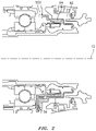
- FIG. 1 is a side partial cross-section view of a turbine engine.
- FIG. 2 is a cross-sectional view of a bearing compartment of a gas turbine engine.
- FIG. 3 is a schematic illustration of an oil drainback system.
- FIG. 4 shows an orifice in a drain tube of a drainback system.
- FIG. 5 illustrates a drain tube with a diffuser device according to one non-limiting embodiment.
- FIGS. 6 and 7 illustrate details of another non-limiting embodiment of a diffuser device.
- FIGS. 8 and 9 illustrate details of another non-limiting embodiment of a diffuser device.
- FIGS. 10 and 11 illustrate details of another non-limiting embodiment of a diffuser device.
- the invention relates to fluid diffusion device for an oil recirculation or drainback system and, more particularly, to such a device for an oil drainback system in a gas turbine engine.
- FIG. 1 shows a side partial cross-section view of a gas turbine engine 10 and includes axial centerline 12 , upstream airflow inlet 14 , downstream airflow exhaust outlet 16 , fan section 18 , compressor section 20 (with low pressure compressor (“LPC”) section 20 A and high pressure compressor (“HPC”) section 20 B), combustor section 22 , turbine section 24 (with high pressure turbine (“HPT”) section 24 A and low pressure turbine (“LPT”) section 24 B), engine housing 26 (with core case 28 and fan case 30 ), fan rotor 32 , LPC rotor 34 , HPC rotor 36 , HPT rotor 38 , LPT rotor 40 , gear train 42 , fan shaft 44 , low speed shaft 46 , high speed shaft 48 , bearing compartments 50 A, 50 B, and 50 C, plurality of bearings 52 , core gas path 54 , bypass gas path 56 , combustion chamber 58 , and combustor 60 .
- LPC low pressure compressor
- HPC high pressure compressor
- HPT high pressure
- the present disclosure related to an oil drainback system for the bearing compartments 50 A, 50 B, 50 C.
- an oil drainback system for the bearing compartments 50 A, 50 B, 50 C.
- FIG. 2 is an enlarged view of components of bearing compartment 50 B of FIG. 1 , and shows surrounding buffer air cavity 62 separated from bearing compartment 50 B by a seal support 64 .
- a drain tube assembly 66 is schematically shown in the lower portion of this drawing and shows the position of oil being re-introduced into the bearing compartment 50 B near the sump after being collected from the buffer air cavity 62 .
- FIG. 3 is a completely schematic illustration of oil flow through and around the bearing compartment 50 B and an accompanying oil drainback system 68 .
- a sump 70 allows oil to flow to a storage tank (not shown) with filters and the like where oil can then be drawn or fed back to the bearing compartment as needed, schematically illustrated by arrow 71 .
- oil which has reached the buffer air cavity 62 is collected in an oil drainback system 68 and returned to the bearing compartment 50 B.
- This oil can be collected, for example by centripetal force and gravity, in a gutter system schematically illustrated at 73 and then flows at pressure typically influenced by pressure in the buffer air area 62 , through an oil flow path 72 to an oil drain tube 74 which typically introduces the collected oil near sump 70 .
- Oil and air in the oil flow path are typically exposed to the higher pressure which can be present in the buffer air cavity 62 , and therefore gas (air) and entrained oil can frequently be introduced back into bearing compartment 50 B at a high velocity from drain tube 74 , which high velocity is schematically illustrated at arrow 76 .
- High velocity flow 76 can interfere with proper scavenging and flow of oil through sump 70 , resulting in this area of the bearing compartment becoming flooded with oil.
- an orifice 78 or other flow restriction has been placed in drain tube 74 to reduce the impact of air flow into the bearing compartment.
- orifices as small as 0.044 inches in diameter have been utilized. However, an orifice this small is extremely prone to blockage with debris that can frequently be present in the flow of air and oil from the sump.
- An in-line orifice as shown in FIG. 4 restricts air flow and this restricted flow is then able to expand into the tube after the restriction, slowing down before exiting the tube into the compartment.
- the diffusers as disclosed herein do not restrict mass flow like the orifice. Rather, they increase the flow area at the exit to allow the mass flow from the drain tube to diffuse as opposed to exiting from the tube and acting like a single jet of air/oil.
- Diffusers as disclosed herein are configured to produce in-line flow velocity less than or equal to that which is produced using an orifice in the line.
- an orifice as shown in FIG. 4 can be used and optimized until an acceptable in-line flow velocity is achieved, that is, one which does not interfere with proper flow to the sump.
- a diffuser such as those disclosed herein can be configured with side openings in various configurations to produce an in-line flow velocity less than or equal to the acceptable in-line velocity, while doing so with diffusion and larger flow openings, thereby reducing the chance of blockage due to debris.
- FIG. 5 shows drain tube 74 mounted to a structure 80 which could be a portion of the structure of bearing compartment 50 B such as a strut or the like.
- a diffuser device 82 can be affixed to an end 84 of drain tube 74 .
- Diffuser device 82 receives flow at end 84 of drain tube 74 and diffuses and re-directs flow from drain tube 74 to remove negative effects of high pressure, high velocity flow into the bearing compartment 50 B.
- diffuser device 82 is also configured to minimize the possibility of blockage from debris.
- FIGS. 6-11 illustrate different non-limiting configurations of a diffuser device and these different configurations are discussed below.
- FIGS. 6 and 7 show diffuser device 82 defined by a sidewall 86 having openings 90 passing through sidewall 86 . These openings are sized and arranged to direct flow laterally out of diffuser device 82 , which both slows the velocity of the flow and also directs it away from the sump in the typical configuration wherein drain tube 74 is pointed at the sump.
- end wall 88 also has an end opening 92 .
- the size and amount of side openings 90 and end opening 92 are configured to reduce velocity of flow out of drain tube 74 in the axial direction of drain tube 74 , while still maintaining the size of all openings large enough to avoid potential blockage by debris.
- sidewall 86 defines a substantially cylindrical shaped structure, with openings 90 arranged around the circumference of the cylinder and also along the length of the cylinder, and with a substantially flat end wall 88 with one centered end opening 92 .
- openings 90 , 92 could be effective as well.
- FIGS. 6 and 7 also show an enlarged portion 94 at one end of diffuser device 82 and this serves to configure diffuser device 82 for attachment to drain tube 74 .
- This can be by way of a press fit, or with a tightening strap (not shown) or any other mechanism including threads, adhesive or the like.
- maintaining diffuser device 82 as a separate part may be more practical for maintenance and cleaning as necessary, and also for the purpose of retro-fitting oil drainback systems with either a straight drain tube or a drain tube with an orifice or other flow restriction.
- FIGS. 8 and 9 illustrate another non-limiting embodiment wherein diffuser device 82 has openings 90 in sidewall 86 , but no end opening.
- end wall 88 is a solid wall. This advantageously completely removes an air vector directly in line with the drain tube 74 , such that all flow is directed laterally.
- This configuration can advantageously have openings 90 defining a flow area of the plurality of holes 90 such that the exit velocity of the air due to the diffusion from going from the drain tube ID of a smaller flow area to this larger flow area created by all the holes is equivalent to or less than the exit velocity of an in-line orifice configuration ( FIG. 4 ) that is known to produce acceptable results.
- FIGS. 10 and 11 illustrate another non-limiting configuration of a diffuser device 82 wherein openings 90 are positioned in sidewall 86 as mentioned above.
- a plurality of end openings 92 are positioned in end wall 88 .
- a baffle, or central flow opening 96 is positioned within diffuser device 82 as shown.
- openings 90 in sidewall 86 can be larger upstream of the baffle, and smaller downstream of the baffle.
- the plurality of end openings 92 are all off direct-center, such that even the end openings produce at least some re-direction of flow along the axis of drain tube 74 and diffuser device 82 .
- openings upstream and downstream of baffle 96 having different sizes, for example with smaller size openings upstream of the baffle and larger size openings downstream of the baffle.
- the configuration of these different size openings, as with other features of the diffuser, can be based on achieving equivalent air exit velocity compared to a conventional orifice design which produces acceptable results with respect to flow at the sump.
- the sizing and placement of the different holes in the diffuser can be configured to produce a flow velocity of similar or less impact than what can be accomplished with an in-line orifice, while greatly reducing susceptibility to plugging due to debris.
- the oil drainback system such as that illustrated in FIG. 3 collects oil from the buffered air cavity and returns this oil back to the bearing compartment to prevent migration of the oil to areas of the engine where oil is not desired. This is accomplished with a gutter system 73 which collects such oil typically assisted by centripetal force and gravity. This collected oil then flows through gas flow path 72 to drain tube 74 .
- the diffuser device as disclosed herein prevents a high velocity stream of air directly from exiting drain tube 74 at a high velocity directed at the sump, and therefore helps to avoid flooding of the sump and excessive air ingestion. Further, the diffuser device is configured to reduce the chance of blockage with debris, thereby providing an oil drainback system which addresses the issues identified above.
- any orifice or flow restriction can be removed from the drain tube and replaced with a diffuser device as disclosed herein, thereby improving functionality of the drainback system without increasing issues of blockage from debris.
Landscapes
- Engineering & Computer Science (AREA)
- General Engineering & Computer Science (AREA)
- Mechanical Engineering (AREA)
- Chemical & Material Sciences (AREA)
- Combustion & Propulsion (AREA)
- Oil, Petroleum & Natural Gas (AREA)
- Supercharger (AREA)
Abstract
Description
Claims (15)
Priority Applications (2)
| Application Number | Priority Date | Filing Date | Title |
|---|---|---|---|
| US16/572,806 US11506079B2 (en) | 2019-09-09 | 2019-09-17 | Fluid diffusion device for sealed bearing compartment drainback system |
| EP20194406.3A EP3789593B1 (en) | 2019-09-09 | 2020-09-03 | Diffuser for an oil drainback system for a bearing compartment of a gas turbine engine and method for upgrading an oil drainback system for a gas turbine engine |
Applications Claiming Priority (2)
| Application Number | Priority Date | Filing Date | Title |
|---|---|---|---|
| US201962897507P | 2019-09-09 | 2019-09-09 | |
| US16/572,806 US11506079B2 (en) | 2019-09-09 | 2019-09-17 | Fluid diffusion device for sealed bearing compartment drainback system |
Publications (2)
| Publication Number | Publication Date |
|---|---|
| US20210071677A1 US20210071677A1 (en) | 2021-03-11 |
| US11506079B2 true US11506079B2 (en) | 2022-11-22 |
Family
ID=72355930
Family Applications (1)
| Application Number | Title | Priority Date | Filing Date |
|---|---|---|---|
| US16/572,806 Active 2041-02-08 US11506079B2 (en) | 2019-09-09 | 2019-09-17 | Fluid diffusion device for sealed bearing compartment drainback system |
Country Status (2)
| Country | Link |
|---|---|
| US (1) | US11506079B2 (en) |
| EP (1) | EP3789593B1 (en) |
Families Citing this family (2)
| Publication number | Priority date | Publication date | Assignee | Title |
|---|---|---|---|---|
| US11719127B2 (en) | 2019-10-23 | 2023-08-08 | Raytheon Technologies Corporation | Oil drainback assembly for a bearing compartment of a gas turbine engine |
| US11970972B2 (en) | 2019-10-23 | 2024-04-30 | Rtx Corporation | Windage blocker for oil routing |
Citations (30)
| Publication number | Priority date | Publication date | Assignee | Title |
|---|---|---|---|---|
| FR2000665A1 (en) | 1968-01-24 | 1969-09-12 | Snam Progetti | |
| US3500869A (en) | 1967-08-02 | 1970-03-17 | American Cyanamid Co | Flexible flattened tubular open-ended article |
| US4862995A (en) * | 1987-06-04 | 1989-09-05 | Steve Faria | Oil discharge diffuser |
| US5261751A (en) | 1990-12-21 | 1993-11-16 | Fag Kugelfischer Georg Schafer Kgaa | Device for removing oil from annular spaces |
| US5813493A (en) | 1997-04-15 | 1998-09-29 | Dana Corporation | Lubrication fluid deflector/baffle for a motor vehicle axle assembly |
| US6199543B1 (en) | 1999-02-18 | 2001-03-13 | Perkins Engines Company Limited | Breather baffle |
| JP2001140654A (en) | 1999-11-12 | 2001-05-22 | Ishikawajima Harima Heavy Ind Co Ltd | Bearing device for turbocharger |
| US7017546B1 (en) | 2004-10-28 | 2006-03-28 | General Motors Corporation | Dry sump oil tank assembly |
| US20080078617A1 (en) * | 2006-09-28 | 2008-04-03 | United Technologies Corporation | Dual mode scavenge scoop |
| US20080190091A1 (en) | 2003-12-17 | 2008-08-14 | Peters Robert E | Bifurcated oil scavenging bearing compartment within a gas turbine engine |
| US20080245614A1 (en) | 2006-12-22 | 2008-10-09 | Rolls-Royce Corporation | Lubricant flow suppressor |
| CN201241753Y (en) | 2008-08-22 | 2009-05-20 | 寿光市康跃增压器有限公司 | Swirl backflow bearing body of turbocharger |
| US20100058729A1 (en) | 2008-09-11 | 2010-03-11 | Rolls-Royce Plc | Lubricant scavenge arrangement |
| US20120060508A1 (en) * | 2009-09-28 | 2012-03-15 | Alecu Daniel T | Gas turbine engine breather exhaust oil collector |
| US20120324899A1 (en) | 2011-06-22 | 2012-12-27 | United Techonologies Corporation | Oil bypass channel deaerator for a geared turbofan engine |
| CN203463452U (en) | 2013-08-27 | 2014-03-05 | 永嘉县永乐高中压标准件有限公司 | Oil-draining bolt |
| CN203730508U (en) | 2014-03-13 | 2014-07-23 | 温州市强杰不锈钢标准件有限公司 | Oil drainage bolt |
| US20150176492A1 (en) | 2013-12-20 | 2015-06-25 | Pratt & Whitney Canada Corp. | Oil tank and scavenge pipe assembly of a gas turbine engine and method of delivering an oil and air mixture to same |
| US20160017812A1 (en) * | 2014-07-01 | 2016-01-21 | William G. Sheridan | Geared gas turbine engine with oil deaerator |
| US9341117B2 (en) | 2012-12-21 | 2016-05-17 | General Electric Company | Combined sump service |
| US20160356179A1 (en) * | 2014-02-26 | 2016-12-08 | Volvo Truck Corporation | Turbocompound unit |
| FR3037614A1 (en) | 2015-06-22 | 2016-12-23 | Snecma | DRAIN FOR TURBOMACHINE EXHAUST CASE |
| WO2018113332A1 (en) * | 2016-12-20 | 2018-06-28 | 中国航发商用航空发动机有限责任公司 | Oil-gas separator, oil-gas separation system and aircraft engine |
| CN207750348U (en) | 2017-11-01 | 2018-08-21 | 海盐哈特惠机械五金制品有限公司 | A kind of oiling bolt |
| US10100735B2 (en) | 2013-10-08 | 2018-10-16 | United Technologies Corporation | Low loss oil accumulator assembly |
| US10287915B2 (en) | 2013-01-15 | 2019-05-14 | United Technologies Corporation | Fluid collection gutter for a geared turbine engine |
| WO2019147778A1 (en) | 2018-01-26 | 2019-08-01 | Siemens Aktiengesellschaft | Journal bearing assembly with drainage facilitation element |
| US20190323382A1 (en) * | 2018-04-23 | 2019-10-24 | Pratt & Whitney Canada Corp. | Sealing assembly for a gas turbine engine |
| US20210123385A1 (en) * | 2019-10-23 | 2021-04-29 | United Technologies Corporation | Windage blocker for oil routing |
| US20210123361A1 (en) | 2019-10-23 | 2021-04-29 | United Technologies Corporation | Oil drainback assembly for a bearing compartment of a gas turbine engine |
Family Cites Families (1)
| Publication number | Priority date | Publication date | Assignee | Title |
|---|---|---|---|---|
| US8500869B1 (en) * | 2012-06-21 | 2013-08-06 | Hamilton Sundstrand Corporation | Anti-rotation deaerator outlet diffuser |
-
2019
- 2019-09-17 US US16/572,806 patent/US11506079B2/en active Active
-
2020
- 2020-09-03 EP EP20194406.3A patent/EP3789593B1/en active Active
Patent Citations (32)
| Publication number | Priority date | Publication date | Assignee | Title |
|---|---|---|---|---|
| US3500869A (en) | 1967-08-02 | 1970-03-17 | American Cyanamid Co | Flexible flattened tubular open-ended article |
| FR2000665A1 (en) | 1968-01-24 | 1969-09-12 | Snam Progetti | |
| US4862995A (en) * | 1987-06-04 | 1989-09-05 | Steve Faria | Oil discharge diffuser |
| US5261751A (en) | 1990-12-21 | 1993-11-16 | Fag Kugelfischer Georg Schafer Kgaa | Device for removing oil from annular spaces |
| US5813493A (en) | 1997-04-15 | 1998-09-29 | Dana Corporation | Lubrication fluid deflector/baffle for a motor vehicle axle assembly |
| US6199543B1 (en) | 1999-02-18 | 2001-03-13 | Perkins Engines Company Limited | Breather baffle |
| JP2001140654A (en) | 1999-11-12 | 2001-05-22 | Ishikawajima Harima Heavy Ind Co Ltd | Bearing device for turbocharger |
| US20080190091A1 (en) | 2003-12-17 | 2008-08-14 | Peters Robert E | Bifurcated oil scavenging bearing compartment within a gas turbine engine |
| US7017546B1 (en) | 2004-10-28 | 2006-03-28 | General Motors Corporation | Dry sump oil tank assembly |
| US20080078617A1 (en) * | 2006-09-28 | 2008-04-03 | United Technologies Corporation | Dual mode scavenge scoop |
| US20080245614A1 (en) | 2006-12-22 | 2008-10-09 | Rolls-Royce Corporation | Lubricant flow suppressor |
| CN201241753Y (en) | 2008-08-22 | 2009-05-20 | 寿光市康跃增压器有限公司 | Swirl backflow bearing body of turbocharger |
| US20100058729A1 (en) | 2008-09-11 | 2010-03-11 | Rolls-Royce Plc | Lubricant scavenge arrangement |
| US20120060508A1 (en) * | 2009-09-28 | 2012-03-15 | Alecu Daniel T | Gas turbine engine breather exhaust oil collector |
| US8621839B2 (en) * | 2009-09-28 | 2014-01-07 | Pratt & Whitney Canada Corp. | Gas turbine engine breather exhaust oil collector |
| US20120324899A1 (en) | 2011-06-22 | 2012-12-27 | United Techonologies Corporation | Oil bypass channel deaerator for a geared turbofan engine |
| US9341117B2 (en) | 2012-12-21 | 2016-05-17 | General Electric Company | Combined sump service |
| US10287915B2 (en) | 2013-01-15 | 2019-05-14 | United Technologies Corporation | Fluid collection gutter for a geared turbine engine |
| CN203463452U (en) | 2013-08-27 | 2014-03-05 | 永嘉县永乐高中压标准件有限公司 | Oil-draining bolt |
| US10100735B2 (en) | 2013-10-08 | 2018-10-16 | United Technologies Corporation | Low loss oil accumulator assembly |
| US20150176492A1 (en) | 2013-12-20 | 2015-06-25 | Pratt & Whitney Canada Corp. | Oil tank and scavenge pipe assembly of a gas turbine engine and method of delivering an oil and air mixture to same |
| US9650957B2 (en) | 2013-12-20 | 2017-05-16 | Pratt & Whitney Canada Corp. | Oil tank and scavenge pipe assembly of a gas turbine engine and method of delivering an oil and air mixture to same |
| US20160356179A1 (en) * | 2014-02-26 | 2016-12-08 | Volvo Truck Corporation | Turbocompound unit |
| CN203730508U (en) | 2014-03-13 | 2014-07-23 | 温州市强杰不锈钢标准件有限公司 | Oil drainage bolt |
| US20160017812A1 (en) * | 2014-07-01 | 2016-01-21 | William G. Sheridan | Geared gas turbine engine with oil deaerator |
| FR3037614A1 (en) | 2015-06-22 | 2016-12-23 | Snecma | DRAIN FOR TURBOMACHINE EXHAUST CASE |
| WO2018113332A1 (en) * | 2016-12-20 | 2018-06-28 | 中国航发商用航空发动机有限责任公司 | Oil-gas separator, oil-gas separation system and aircraft engine |
| CN207750348U (en) | 2017-11-01 | 2018-08-21 | 海盐哈特惠机械五金制品有限公司 | A kind of oiling bolt |
| WO2019147778A1 (en) | 2018-01-26 | 2019-08-01 | Siemens Aktiengesellschaft | Journal bearing assembly with drainage facilitation element |
| US20190323382A1 (en) * | 2018-04-23 | 2019-10-24 | Pratt & Whitney Canada Corp. | Sealing assembly for a gas turbine engine |
| US20210123385A1 (en) * | 2019-10-23 | 2021-04-29 | United Technologies Corporation | Windage blocker for oil routing |
| US20210123361A1 (en) | 2019-10-23 | 2021-04-29 | United Technologies Corporation | Oil drainback assembly for a bearing compartment of a gas turbine engine |
Non-Patent Citations (3)
| Title |
|---|
| EP Search Report dated Mar. 3, 2021 issued for corresponding European Patent Application No. 20202903.9. |
| EP Search Report dated Mar. 5, 2021 issued for corresponding European Patent Application No. 20203444.3. |
| European search report for patent application No. 20 19 4406 dated Jan. 26, 2021. |
Also Published As
| Publication number | Publication date |
|---|---|
| US20210071677A1 (en) | 2021-03-11 |
| EP3789593A1 (en) | 2021-03-10 |
| EP3789593B1 (en) | 2024-10-30 |
Similar Documents
| Publication | Publication Date | Title |
|---|---|---|
| US7827798B2 (en) | System for ventilating a combustion chamber wall in a turbomachine | |
| JP5188408B2 (en) | Deoiling device and turbomachine equipped with the device | |
| US8210316B2 (en) | Oil scavenge system for a gas turbine engine | |
| US7658077B2 (en) | System for deicing an aircraft turbine engine inlet cone | |
| CA2714861C (en) | Gas turbine engine breather exhaust oil collector | |
| US10494949B2 (en) | Oil cooling systems for a gas turbine engine | |
| US10322621B2 (en) | Inertial particle separator for air cycle machine | |
| EP2586534B1 (en) | A centrifugal separator, an internal combustion engine and centrifugal separator assembly and a method of separating contaminants from crankcase gas | |
| JP2005507044A (en) | Passive cooling system for auxiliary power plant equipment | |
| EP3812603B1 (en) | Oil drainback assembly for a bearing compartment of a gas turbine engine | |
| US11506079B2 (en) | Fluid diffusion device for sealed bearing compartment drainback system | |
| CA2606580C (en) | Improved inlet plenum for gas turbine engine | |
| US9618001B2 (en) | Turbocharger | |
| US10507410B2 (en) | Air-oil separation apparatus | |
| KR20180130538A (en) | Turbocharger bearing housing Flow strut for oil core | |
| CN109869346B (en) | Compressor shell | |
| RU2594209C2 (en) | Oil discharge device for and turbomachine containing such a device | |
| US11970972B2 (en) | Windage blocker for oil routing | |
| US11168585B2 (en) | Geared gas turbine engine with improved breather air venting | |
| CN205370684U (en) | High -efficient non -maintaining oil and gas separator | |
| CN106457101B (en) | Filtering a gas/particle stream | |
| JP2016084710A (en) | Turbocharger | |
| KR101942356B1 (en) | Apparatus for treating oil mist and fume of turbocharger | |
| KR101942354B1 (en) | Apparatus for treating oil mist and fume of turbocharger | |
| KR101942355B1 (en) | Apparatus for treating oil mist and fume of turbocharger |
Legal Events
| Date | Code | Title | Description |
|---|---|---|---|
| AS | Assignment |
Owner name: UNITED TECHNOLOGIES CORPORATION, CONNECTICUT Free format text: ASSIGNMENT OF ASSIGNORS INTEREST;ASSIGNORS:SCHWENDENMANN, ANDREW V.;PARNIN, FRANCIS;GOMES, MATTHEW;REEL/FRAME:050396/0794 Effective date: 20190912 |
|
| FEPP | Fee payment procedure |
Free format text: ENTITY STATUS SET TO UNDISCOUNTED (ORIGINAL EVENT CODE: BIG.); ENTITY STATUS OF PATENT OWNER: LARGE ENTITY |
|
| AS | Assignment |
Owner name: RAYTHEON TECHNOLOGIES CORPORATION, CONNECTICUT Free format text: CHANGE OF NAME;ASSIGNOR:UNITED TECHNOLOGIES CORPORATION;REEL/FRAME:057190/0719 Effective date: 20200403 |
|
| AS | Assignment |
Owner name: RAYTHEON TECHNOLOGIES CORPORATION, CONNECTICUT Free format text: CORRECTIVE ASSIGNMENT TO CORRECT THE SPELLING ON THE ADDRESS 10 FARM SPRINGD ROAD FARMINGTONCONNECTICUT 06032 PREVIOUSLY RECORDED ON REEL 057190 FRAME 0719. ASSIGNOR(S) HEREBY CONFIRMS THE CORRECT SPELLING OF THE ADDRESS 10 FARM SPRINGS ROAD FARMINGTON CONNECTICUT 06032;ASSIGNOR:UNITED TECHNOLOGIES CORPORATION;REEL/FRAME:057226/0390 Effective date: 20200403 |
|
| STPP | Information on status: patent application and granting procedure in general |
Free format text: DOCKETED NEW CASE - READY FOR EXAMINATION |
|
| STPP | Information on status: patent application and granting procedure in general |
Free format text: NON FINAL ACTION MAILED |
|
| STPP | Information on status: patent application and granting procedure in general |
Free format text: RESPONSE TO NON-FINAL OFFICE ACTION ENTERED AND FORWARDED TO EXAMINER |
|
| STPP | Information on status: patent application and granting procedure in general |
Free format text: NOTICE OF ALLOWANCE MAILED -- APPLICATION RECEIVED IN OFFICE OF PUBLICATIONS |
|
| STCF | Information on status: patent grant |
Free format text: PATENTED CASE |
|
| AS | Assignment |
Owner name: RTX CORPORATION, CONNECTICUT Free format text: CHANGE OF NAME;ASSIGNOR:RAYTHEON TECHNOLOGIES CORPORATION;REEL/FRAME:064714/0001 Effective date: 20230714 |