US11503305B2 - Method and apparatus for processing video signal - Google Patents
Method and apparatus for processing video signal Download PDFInfo
- Publication number
- US11503305B2 US11503305B2 US16/321,966 US201716321966A US11503305B2 US 11503305 B2 US11503305 B2 US 11503305B2 US 201716321966 A US201716321966 A US 201716321966A US 11503305 B2 US11503305 B2 US 11503305B2
- Authority
- US
- United States
- Prior art keywords
- block
- tree partitioning
- split
- binary
- coding block
- Prior art date
- Legal status (The legal status is an assumption and is not a legal conclusion. Google has not performed a legal analysis and makes no representation as to the accuracy of the status listed.)
- Active
Links
- 238000000034 method Methods 0.000 title claims abstract description 78
- 238000012545 processing Methods 0.000 title claims description 16
- 238000000638 solvent extraction Methods 0.000 claims description 125
- 238000005192 partition Methods 0.000 claims description 67
- 230000008569 process Effects 0.000 claims description 14
- 230000002123 temporal effect Effects 0.000 description 54
- 239000013598 vector Substances 0.000 description 49
- 238000010586 diagram Methods 0.000 description 27
- 238000013139 quantization Methods 0.000 description 18
- 230000008707 rearrangement Effects 0.000 description 15
- 238000001914 filtration Methods 0.000 description 13
- 239000000470 constituent Substances 0.000 description 7
- 238000012937 correction Methods 0.000 description 7
- 208000037170 Delayed Emergence from Anesthesia Diseases 0.000 description 6
- 241000023320 Luma <angiosperm> Species 0.000 description 5
- 230000003044 adaptive effect Effects 0.000 description 5
- OSWPMRLSEDHDFF-UHFFFAOYSA-N methyl salicylate Chemical compound COC(=O)C1=CC=CC=C1O OSWPMRLSEDHDFF-UHFFFAOYSA-N 0.000 description 5
- 230000006870 function Effects 0.000 description 4
- 230000006835 compression Effects 0.000 description 3
- 238000007906 compression Methods 0.000 description 3
- 230000000694 effects Effects 0.000 description 3
- 230000008859 change Effects 0.000 description 2
- 238000009499 grossing Methods 0.000 description 2
- 238000012986 modification Methods 0.000 description 2
- 230000004048 modification Effects 0.000 description 2
- 230000001131 transforming effect Effects 0.000 description 2
- 230000008901 benefit Effects 0.000 description 1
- 230000003287 optical effect Effects 0.000 description 1
- 230000001151 other effect Effects 0.000 description 1
- 238000010845 search algorithm Methods 0.000 description 1
- 238000012546 transfer Methods 0.000 description 1
- 230000009466 transformation Effects 0.000 description 1
Images


Classifications
-
- H—ELECTRICITY
- H04—ELECTRIC COMMUNICATION TECHNIQUE
- H04N—PICTORIAL COMMUNICATION, e.g. TELEVISION
- H04N19/00—Methods or arrangements for coding, decoding, compressing or decompressing digital video signals
- H04N19/10—Methods or arrangements for coding, decoding, compressing or decompressing digital video signals using adaptive coding
- H04N19/102—Methods or arrangements for coding, decoding, compressing or decompressing digital video signals using adaptive coding characterised by the element, parameter or selection affected or controlled by the adaptive coding
- H04N19/103—Selection of coding mode or of prediction mode
- H04N19/105—Selection of the reference unit for prediction within a chosen coding or prediction mode, e.g. adaptive choice of position and number of pixels used for prediction
-
- H—ELECTRICITY
- H04—ELECTRIC COMMUNICATION TECHNIQUE
- H04N—PICTORIAL COMMUNICATION, e.g. TELEVISION
- H04N19/00—Methods or arrangements for coding, decoding, compressing or decompressing digital video signals
- H04N19/10—Methods or arrangements for coding, decoding, compressing or decompressing digital video signals using adaptive coding
- H04N19/102—Methods or arrangements for coding, decoding, compressing or decompressing digital video signals using adaptive coding characterised by the element, parameter or selection affected or controlled by the adaptive coding
- H04N19/103—Selection of coding mode or of prediction mode
-
- H—ELECTRICITY
- H04—ELECTRIC COMMUNICATION TECHNIQUE
- H04N—PICTORIAL COMMUNICATION, e.g. TELEVISION
- H04N19/00—Methods or arrangements for coding, decoding, compressing or decompressing digital video signals
- H04N19/10—Methods or arrangements for coding, decoding, compressing or decompressing digital video signals using adaptive coding
- H04N19/102—Methods or arrangements for coding, decoding, compressing or decompressing digital video signals using adaptive coding characterised by the element, parameter or selection affected or controlled by the adaptive coding
- H04N19/117—Filters, e.g. for pre-processing or post-processing
-
- H—ELECTRICITY
- H04—ELECTRIC COMMUNICATION TECHNIQUE
- H04N—PICTORIAL COMMUNICATION, e.g. TELEVISION
- H04N19/00—Methods or arrangements for coding, decoding, compressing or decompressing digital video signals
- H04N19/10—Methods or arrangements for coding, decoding, compressing or decompressing digital video signals using adaptive coding
- H04N19/102—Methods or arrangements for coding, decoding, compressing or decompressing digital video signals using adaptive coding characterised by the element, parameter or selection affected or controlled by the adaptive coding
- H04N19/119—Adaptive subdivision aspects, e.g. subdivision of a picture into rectangular or non-rectangular coding blocks
-
- H—ELECTRICITY
- H04—ELECTRIC COMMUNICATION TECHNIQUE
- H04N—PICTORIAL COMMUNICATION, e.g. TELEVISION
- H04N19/00—Methods or arrangements for coding, decoding, compressing or decompressing digital video signals
- H04N19/10—Methods or arrangements for coding, decoding, compressing or decompressing digital video signals using adaptive coding
- H04N19/102—Methods or arrangements for coding, decoding, compressing or decompressing digital video signals using adaptive coding characterised by the element, parameter or selection affected or controlled by the adaptive coding
- H04N19/132—Sampling, masking or truncation of coding units, e.g. adaptive resampling, frame skipping, frame interpolation or high-frequency transform coefficient masking
-
- H—ELECTRICITY
- H04—ELECTRIC COMMUNICATION TECHNIQUE
- H04N—PICTORIAL COMMUNICATION, e.g. TELEVISION
- H04N19/00—Methods or arrangements for coding, decoding, compressing or decompressing digital video signals
- H04N19/10—Methods or arrangements for coding, decoding, compressing or decompressing digital video signals using adaptive coding
- H04N19/134—Methods or arrangements for coding, decoding, compressing or decompressing digital video signals using adaptive coding characterised by the element, parameter or criterion affecting or controlling the adaptive coding
- H04N19/157—Assigned coding mode, i.e. the coding mode being predefined or preselected to be further used for selection of another element or parameter
- H04N19/159—Prediction type, e.g. intra-frame, inter-frame or bidirectional frame prediction
-
- H—ELECTRICITY
- H04—ELECTRIC COMMUNICATION TECHNIQUE
- H04N—PICTORIAL COMMUNICATION, e.g. TELEVISION
- H04N19/00—Methods or arrangements for coding, decoding, compressing or decompressing digital video signals
- H04N19/10—Methods or arrangements for coding, decoding, compressing or decompressing digital video signals using adaptive coding
- H04N19/169—Methods or arrangements for coding, decoding, compressing or decompressing digital video signals using adaptive coding characterised by the coding unit, i.e. the structural portion or semantic portion of the video signal being the object or the subject of the adaptive coding
- H04N19/17—Methods or arrangements for coding, decoding, compressing or decompressing digital video signals using adaptive coding characterised by the coding unit, i.e. the structural portion or semantic portion of the video signal being the object or the subject of the adaptive coding the unit being an image region, e.g. an object
- H04N19/176—Methods or arrangements for coding, decoding, compressing or decompressing digital video signals using adaptive coding characterised by the coding unit, i.e. the structural portion or semantic portion of the video signal being the object or the subject of the adaptive coding the unit being an image region, e.g. an object the region being a block, e.g. a macroblock
-
- H—ELECTRICITY
- H04—ELECTRIC COMMUNICATION TECHNIQUE
- H04N—PICTORIAL COMMUNICATION, e.g. TELEVISION
- H04N19/00—Methods or arrangements for coding, decoding, compressing or decompressing digital video signals
- H04N19/10—Methods or arrangements for coding, decoding, compressing or decompressing digital video signals using adaptive coding
- H04N19/169—Methods or arrangements for coding, decoding, compressing or decompressing digital video signals using adaptive coding characterised by the coding unit, i.e. the structural portion or semantic portion of the video signal being the object or the subject of the adaptive coding
- H04N19/186—Methods or arrangements for coding, decoding, compressing or decompressing digital video signals using adaptive coding characterised by the coding unit, i.e. the structural portion or semantic portion of the video signal being the object or the subject of the adaptive coding the unit being a colour or a chrominance component
-
- H—ELECTRICITY
- H04—ELECTRIC COMMUNICATION TECHNIQUE
- H04N—PICTORIAL COMMUNICATION, e.g. TELEVISION
- H04N19/00—Methods or arrangements for coding, decoding, compressing or decompressing digital video signals
- H04N19/44—Decoders specially adapted therefor, e.g. video decoders which are asymmetric with respect to the encoder
-
- H—ELECTRICITY
- H04—ELECTRIC COMMUNICATION TECHNIQUE
- H04N—PICTORIAL COMMUNICATION, e.g. TELEVISION
- H04N19/00—Methods or arrangements for coding, decoding, compressing or decompressing digital video signals
- H04N19/50—Methods or arrangements for coding, decoding, compressing or decompressing digital video signals using predictive coding
- H04N19/503—Methods or arrangements for coding, decoding, compressing or decompressing digital video signals using predictive coding involving temporal prediction
- H04N19/51—Motion estimation or motion compensation
- H04N19/513—Processing of motion vectors
- H04N19/517—Processing of motion vectors by encoding
- H04N19/52—Processing of motion vectors by encoding by predictive encoding
-
- H—ELECTRICITY
- H04—ELECTRIC COMMUNICATION TECHNIQUE
- H04N—PICTORIAL COMMUNICATION, e.g. TELEVISION
- H04N19/00—Methods or arrangements for coding, decoding, compressing or decompressing digital video signals
- H04N19/50—Methods or arrangements for coding, decoding, compressing or decompressing digital video signals using predictive coding
- H04N19/503—Methods or arrangements for coding, decoding, compressing or decompressing digital video signals using predictive coding involving temporal prediction
- H04N19/51—Motion estimation or motion compensation
- H04N19/55—Motion estimation with spatial constraints, e.g. at image or region borders
-
- H—ELECTRICITY
- H04—ELECTRIC COMMUNICATION TECHNIQUE
- H04N—PICTORIAL COMMUNICATION, e.g. TELEVISION
- H04N19/00—Methods or arrangements for coding, decoding, compressing or decompressing digital video signals
- H04N19/70—Methods or arrangements for coding, decoding, compressing or decompressing digital video signals characterised by syntax aspects related to video coding, e.g. related to compression standards
-
- H—ELECTRICITY
- H04—ELECTRIC COMMUNICATION TECHNIQUE
- H04N—PICTORIAL COMMUNICATION, e.g. TELEVISION
- H04N19/00—Methods or arrangements for coding, decoding, compressing or decompressing digital video signals
- H04N19/80—Details of filtering operations specially adapted for video compression, e.g. for pixel interpolation
Definitions
- the present invention relates to a method and an apparatus for processing video signal.
- HD images high definition (HD) images and ultra-high definition (UHD) images
- UHD ultra-high definition
- higher resolution and quality image data has increasing amounts of data in comparison with conventional image data. Therefore, when transmitting image data by using a medium such as conventional wired and wireless broadband networks, or when storing image data by using a conventional storage medium, costs of transmitting and storing increase.
- high-efficiency image encoding/decoding techniques may be utilized.
- Image compression technology includes various techniques, including: an inter-prediction technique of predicting a pixel value included in a current picture from a previous or subsequent picture of the current picture; an intra-prediction technique of predicting a pixel value included in a current picture by using pixel information in the current picture; an entropy encoding technique of assigning a short code to a value with a high appearance frequency and assigning a long code to a value with a low appearance frequency; etc.
- Image data may be effectively compressed by using such image compression technology, and may be transmitted or stored.
- An object of the present invention is to provide a method and an apparatus for efficiently performing inter prediction for an encoding/decoding target block in encoding/decoding a video signal.
- An object of the present invention is to provide a method and an apparatus for deriving a merge candidate based on a block having a pre-determined shape or a pre-determined size in encoding/decoding a video signal.
- An object of the present invention is to provide a method and an apparatus for performing a merge in parallel in a unit of a pre-determined shape or a pre-determined size in encoding/decoding a video signal.
- a method and an apparatus for decoding a video signal according to the present invention may derive a spatial merge candidate for a current block, generate a merge candidate list for the current block based on the spatial merge candidate, obtain motion information for the current block based on the merge candidate list, and perform motion compensation for the current block using the motion information.
- a method and an apparatus for encoding a video signal according to the present invention may derive a spatial merge candidate for a current block, generate a merge candidate list for the current block based on the spatial merge candidate, obtain motion information for the current block based on the merge candidate list, and perform motion compensation for the current block using the motion information.
- the spatial merge candidate of the current block may be derived based on a block having the pre-defined shape or having a size equal to or greater than the pre-defined size, the block comprising the current block.
- the pre-defined shape may be a square shape.
- the current block may have a same spatial merge candidate as a neighboring block included in the block of the square shape with the current block.
- the spatial merge candidate may be determined to be unavailable.
- the merge estimation region may have a square shape or a non-square shape.
- a number of candidate shapes of merge candidates that the merge estimation region is able to have may be restricted by a pre-defined number.
- an efficient inter prediction may be performed for an encoding/decoding target block.
- a merge candidate may be derived based on a block having a pre-determined shape or a pre-determined size.
- a merge can be performed in parallel in a unit of a pre-determined shape or a pre-determined size.
- intra prediction for an encoding/decoding target block may be performed by selecting at least one of a plurality of reference lines.
- a reference line may be derived based on a block having a pre-determined shape or having a size equal to or greater than a pre-determined size.
- an intra filter may be applied to at least one of a plurality of reference lines.
- an intra prediction mode or a number of the intra prediction mode may be adaptively determined according to a reference line used for intra prediction of a current block.
- FIG. 1 is a block diagram illustrating a device for encoding a video according to an embodiment of the present invention.
- FIG. 2 is a block diagram illustrating a device for decoding a video according to an embodiment of the present invention.
- FIG. 3 is a diagram illustrating an example of hierarchically partitioning a coding block based on a tree structure according to an embodiment of the present invention.
- FIG. 4 is a diagram illustrating a partition type in which binary tree-based partitioning is allowed according to an embodiment of the present invention.
- FIGS. 5A and 5B are diagrams illustrating an example in which only a binary tree-based partition of a pre-determined type is allowed according to an embodiment of the present invention.
- FIG. 6 is a diagram for explaining an example in which information related to the allowable number of binary tree partitioning is encoded/decoded, according to an embodiment to which the present invention is applied.
- FIG. 7 is a diagram illustrating a partition mode applicable to a coding block according to an embodiment of the present invention.
- FIG. 8 is a flowchart illustrating an inter prediction method according to an embodiment of the present invention.
- FIG. 9 is a diagram illustrating a process of deriving motion information of a current block when a merge mode is applied to a current block.
- FIG. 10 illustrates a process of deriving motion information of a current block when an AMVP mode is applied to the current block.
- FIG. 11 is a diagram showing a spatial merge candidate of a current block.
- FIG. 12 is a diagram showing a co-located block of a current block.
- FIG. 13 is a diagram for explaining an example of obtaining a motion vector of a temporal merge candidate by scaling a motion vector of a co-located block.
- FIG. 14 is a diagram showing an example of deriving a merge candidate of a non-square block on the basis of a square block.
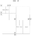
- FIG. 15 is a diagram for explaining an example in which a merge candidate of a binary-tree partitioned block is derived based on an upper node block.
- FIG. 16 is a diagram illustrating an example of determining availability of a spatial merge candidate according to a merge estimation region.
- FIG. 17 is a flowchart illustrating processes of obtaining a residual sample according to an embodiment to which the present invention is applied.
- first ‘first’, ‘second’, etc. can be used to describe various components, but the components are not to be construed as being limited to the terms. The terms are only used to differentiate one component from other components.
- the ‘first’ component may be named the ‘second’ component without departing from the scope of the present invention, and the ‘second’ component may also be similarly named the ‘first’ component.
- the term ‘and/or’ includes a combination of a plurality of items or any one of a plurality of terms.
- FIG. 1 is a block diagram illustrating a device for encoding a video according to an embodiment of the present invention.
- the device 100 for encoding a video may include: a picture partitioning module 110 , prediction modules 120 and 125 , a transform module 130 , a quantization module 135 , a rearrangement module 160 , an entropy encoding module 165 , an inverse quantization module 140 , an inverse transform module 145 , a filter module 150 , and a memory 155 .
- each constitutional part shown in FIG. 1 are independently shown so as to represent characteristic functions different from each other in the device for encoding a video.
- each constitutional part is constituted in a constitutional unit of separated hardware or software.
- each constitutional part includes each of enumerated constitutional parts for convenience.
- at least two constitutional parts of each constitutional part may be combined to form one constitutional part or one constitutional part may be divided into a plurality of constitutional parts to perform each function.
- the embodiment where each constitutional part is combined and the embodiment where one constitutional part is divided are also included in the scope of the present invention, if not departing from the essence of the present invention.
- constituents may not be indispensable constituents performing essential functions of the present invention but be selective constituents improving only performance thereof.
- the present invention may be implemented by including only the indispensable constitutional parts for implementing the essence of the present invention except the constituents used in improving performance.
- the structure including only the indispensable constituents except the selective constituents used in improving only performance is also included in the scope of the present invention.
- the picture partitioning module 110 may partition an input picture into one or more processing units.
- the processing unit may be a prediction unit (PU), a transform unit (TU), or a coding unit (CU).
- the picture partitioning module 110 may partition one picture into combinations of multiple coding units, prediction units, and transform units, and may encode a picture by selecting one combination of coding units, prediction units, and transform units with a predetermined criterion (e.g., cost function).
- a predetermined criterion e.g., cost function
- one picture may be partitioned into multiple coding units.
- a recursive tree structure such as a quad tree structure, may be used to partition a picture into coding units.
- a coding unit which is partitioned into other coding units with one picture or a largest coding unit as a root may be partitioned with child nodes corresponding to the number of partitioned coding units.
- a coding unit which is no longer partitioned by a predetermined limitation serves as a leaf node. That is, when it is assumed that only square partitioning is possible for one coding unit, one coding unit may be partitioned into four other coding units at most.
- the coding unit may mean a unit performing encoding, or a unit performing decoding.
- a prediction unit may be one of partitions partitioned into a square or a rectangular shape having the same size in a single coding unit, or a prediction unit may be one of partitions partitioned so as to have a different shape/size in a single coding unit.
- intra prediction may be performed without partitioning the coding unit into multiple prediction units N ⁇ N.
- the prediction modules 120 and 125 may include an inter prediction module 120 performing inter prediction and an intra prediction module 125 performing intra prediction. Whether to perform inter prediction or intra prediction for the prediction unit may be determined, and detailed information (e.g., an intra prediction mode, a motion vector, a reference picture, etc.) according to each prediction method may be determined.
- the processing unit subjected to prediction may be different from the processing unit for which the prediction method and detailed content is determined.
- the prediction method, the prediction mode, etc. may be determined by the prediction unit, and prediction may be performed by the transform unit.
- a residual value (residual block) between the generated prediction block and an original block may be input to the transform module 130 .
- the used for prediction may be encoded with the residual value by the entropy encoding module 165 and may be transmitted to a device for decoding a video.
- a particular encoding mode it is possible to transmit to a device for decoding video by encoding the original block as it is without generating the prediction block through the prediction modules 120 and 125 .
- the inter prediction module 120 may predict the prediction unit based on information of at least one of a previous picture or a subsequent picture of the current picture, or may predict the prediction unit based on information of some encoded regions in the current picture, in some cases.
- the inter prediction module 120 may include a reference picture interpolation module, a motion prediction module, and a motion compensation module.
- the reference picture interpolation module may receive reference picture information from the memory 155 and may generate pixel information of an integer pixel or less then the integer pixel from the reference picture.
- an 8-tap DCT-based interpolation filter having different filter coefficients may be used to generate pixel information of an integer pixel or less than an integer pixel in a unit of a 1 ⁇ 4 pixel.
- a 4-tap DCT-based interpolation filter having different filter coefficient may be used to generate pixel information of an integer pixel or less than an integer pixel in a unit of a 1 ⁇ 8 pixel.
- the motion prediction module may perform motion prediction based on the reference picture interpolated by the reference picture interpolation module.
- various methods such as a full search-based block matching algorithm (FBMA), a three step search (TSS), a new three-step search algorithm (NTS), etc.
- FBMA full search-based block matching algorithm
- TSS three step search
- NTS new three-step search algorithm
- the motion vector may have a motion vector value in a unit of a 1 ⁇ 2 pixel or a 1 ⁇ 4 pixel based on an interpolated pixel.
- the motion prediction module may predict a current prediction unit by changing the motion prediction method.
- various methods such as a skip method, a merge method, an AMVP (Advanced Motion Vector Prediction) method, an intra block copy method, etc., may be used.
- AMVP Advanced Motion Vector Prediction
- the intra prediction module 125 may generate a prediction unit based on reference pixel information neighboring to a current block which is pixel information in the current picture.
- the neighboring block of the current prediction unit is a block subjected to inter prediction and thus a reference pixel is a pixel subjected to inter prediction
- the reference pixel included in the block subjected to inter prediction may be replaced with reference pixel information of a neighboring block subjected to intra prediction. That is, when a reference pixel is not available, at least one reference pixel of available reference pixels may be used instead of unavailable reference pixel information.
- Prediction modes in intra prediction may include a directional prediction mode using reference pixel information depending on a prediction direction and a non-directional prediction mode not using directional information in performing prediction.
- a mode for predicting luma information may be different from a mode for predicting chroma information, and in order to predict the chroma information, intra prediction mode information used to predict luma information or predicted luma signal information may be utilized.
- intra prediction when the size of the prediction unit is the same as the size of the transform unit, intra prediction may be performed on the prediction unit based on pixels positioned at the left, the top left, and the top of the prediction unit. However, in performing intra prediction, when the size of the prediction unit is different from the size of the transform unit, intra prediction may be performed using a reference pixel based on the transform unit. Also, intra prediction using N ⁇ N partitioning may be used for only the smallest coding unit.
- a prediction block may be generated after applying an AIS (Adaptive Intra Smoothing) filter to a reference pixel depending on the prediction modes.
- the type of the AIS filter applied to the reference pixel may vary.
- an intra prediction mode of the current prediction unit may be predicted from the intra prediction mode of the prediction unit neighboring to the current prediction unit.
- mode information predicted from the neighboring prediction unit when the intra prediction mode of the current prediction unit is the same as the intra prediction mode of the neighboring prediction unit, information indicating that the prediction modes of the current prediction unit and the neighboring prediction unit are equal to each other may be transmitted using predetermined flag information.
- entropy encoding may be performed to encode prediction mode information of the current block.
- a residual block including information on a residual value which is a different between the prediction unit subjected to prediction and the original block of the prediction unit may be generated based on prediction units generated by the prediction modules 120 and 125 .
- the generated residual block may be input to the transform module 130 .
- the transform module 130 may transform the residual block including the information on the residual value between the original block and the prediction unit generated by the prediction modules 120 and 125 by using a transform method, such as discrete cosine transform (DCT), discrete sine transform (DST), and KLT. Whether to apply DCT, DST, or KLT in order to transform the residual block may be determined based on intra prediction mode information of the prediction unit used to generate the residual block.
- a transform method such as discrete cosine transform (DCT), discrete sine transform (DST), and KLT.
- the quantization module 135 may quantize values transformed to a frequency domain by the transform module 130 . Quantization coefficients may vary depending on the block or importance of a picture. The values calculated by the quantization module 135 may be provided to the inverse quantization module 140 and the rearrangement module 160 .
- the rearrangement module 160 may rearrange coefficients of quantized residual values.
- the rearrangement module 160 may change a coefficient in the form of a two-dimensional block into a coefficient in the form of a one-dimensional vector through a coefficient scanning method. For example, the rearrangement module 160 may scan from a DC coefficient to a coefficient in a high frequency domain using a zigzag scanning method so as to change the coefficients to be in the form of one-dimensional vectors.
- vertical direction scanning where coefficients in the form of two-dimensional blocks are scanned in the column direction or horizontal direction scanning where coefficients in the form of two-dimensional blocks are scanned in the row direction may be used instead of zigzag scanning. That is, which scanning method among zigzag scanning, vertical direction scanning, and horizontal direction scanning is used may be determined depending on the size of the transform unit and the intra prediction mode.
- the entropy encoding module 165 may perform entropy encoding based on the values calculated by the rearrangement module 160 .
- Entropy encoding may use various encoding methods, for example, exponential Golomb coding, context-adaptive variable length coding (CAVLC), and context-adaptive binary arithmetic coding (CABAC).
- the entropy encoding module 165 may encode a variety of information, such as residual value coefficient information and block type information of the coding unit, prediction mode information, partition unit information, prediction unit information, transform unit information, motion vector information, reference frame information, block interpolation information, filtering information, etc. from the rearrangement module 160 and the prediction modules 120 and 125 .
- the entropy encoding module 165 may entropy encode the coefficients of the coding unit input from the rearrangement module 160 .
- the inverse quantization module 140 may inversely quantize the values quantized by the quantization module 135 and the inverse transform module 145 may inversely transform the values transformed by the transform module 130 .
- the residual value generated by the inverse quantization module 140 and the inverse transform module 145 may be combined with the prediction unit predicted by a motion estimation module, a motion compensation module, and the intra prediction module of the prediction modules 120 and 125 such that a reconstructed block can be generated.
- the filter module 150 may include at least one of a deblocking filter, an offset correction unit, and an adaptive loop filter (ALF).
- a deblocking filter may include at least one of a deblocking filter, an offset correction unit, and an adaptive loop filter (ALF).
- ALF adaptive loop filter
- the deblocking filter may remove block distortion that occurs due to boundaries between the blocks in the reconstructed picture.
- the pixels included in several rows or columns in the block may be a basis of determining whether to apply the deblocking filter to the current block.
- a strong filter or a weak filter may be applied depending on required deblocking filtering strength.
- horizontal direction filtering and vertical direction filtering may be processed in parallel.
- the offset correction module may correct offset with the original picture in a unit of a pixel in the picture subjected to deblocking.
- Adaptive loop filtering may be performed based on the value obtained by comparing the filtered reconstructed picture and the original picture.
- the pixels included in the picture may be divided into predetermined groups, a filter to be applied to each of the groups may be determined, and filtering may be individually performed for each group.
- Information on whether to apply ALF and a luma signal may be transmitted by coding units (CU).
- the shape and filter coefficient of a filter for ALF may vary depending on each block. Also, the filter for ALF in the same shape (fixed shape) may be applied regardless of characteristics of the application target block.
- the memory 155 may store the reconstructed block or picture calculated through the filter module 150 .
- the stored reconstructed block or picture may be provided to the prediction modules 120 and 125 in performing inter prediction.
- FIG. 2 is a block diagram illustrating a device for decoding a video according to an embodiment of the present invention.
- the device 200 for decoding a video may include: an entropy decoding module 210 , a rearrangement module 215 , an inverse quantization module 220 , an inverse transform module 225 , prediction modules 230 and 235 , a filter module 240 , and a memory 245 .
- the input bitstream may be decoded according to an inverse process of the device for encoding a video.
- the entropy decoding module 210 may perform entropy decoding according to an inverse process of entropy encoding by the entropy encoding module of the device for encoding a video. For example, corresponding to the methods performed by the device for encoding a video, various methods, such as exponential Golomb coding, context-adaptive variable length coding (CAVLC), and context-adaptive binary arithmetic coding (CABAC) may be applied.
- various methods such as exponential Golomb coding, context-adaptive variable length coding (CAVLC), and context-adaptive binary arithmetic coding (CABAC) may be applied.
- the entropy decoding module 210 may decode information on intra prediction and inter prediction performed by the device for encoding a video.
- the rearrangement module 215 may perform rearrangement on the bitstream entropy decoded by the entropy decoding module 210 based on the rearrangement method used in the device for encoding a video.
- the rearrangement module may reconstruct and rearrange the coefficients in the form of one-dimensional vectors to the coefficient in the form of two-dimensional blocks.
- the rearrangement module 215 may receive information related to coefficient scanning performed in the device for encoding a video and may perform rearrangement via a method of inversely scanning the coefficients based on the scanning order performed in the device for encoding a video.
- the inverse quantization module 220 may perform inverse quantization based on a quantization parameter received from the device for encoding a video and the rearranged coefficients of the block.
- the inverse transform module 225 may perform the inverse transform, i.e., inverse DCT, inverse DST, and inverse KLT, which is the inverse process of transform, i.e., DCT, DST, and KLT, performed by the transform module on the quantization result by the device for encoding a video.
- Inverse transform may be performed based on a transfer unit determined by the device for encoding a video.
- the inverse transform module 225 of the device for decoding a video may selectively perform transform schemes (e.g., DCT, DST, and KLT) depending on multiple pieces of information, such as the prediction method, the size of the current block, the prediction direction, etc.
- transform schemes e.g., DCT, DST, and KLT
- the prediction modules 230 and 235 may generate a prediction block based on information on prediction block generation received from the entropy decoding module 210 and previously decoded block or picture information received from the memory 245 .
- intra prediction when the size of the prediction unit is the same as the size of the transform unit, intra prediction may be performed on the prediction unit based on the pixels positioned at the left, the top left, and the top of the prediction unit.
- intra prediction when the size of the prediction unit is different from the size of the transform unit, intra prediction may be performed using a reference pixel based on the transform unit.
- intra prediction using N ⁇ N partitioning may be used for only the smallest coding unit.
- the prediction modules 230 and 235 may include a prediction unit determination module, an inter prediction module, and an intra prediction module.
- the prediction unit determination module may receive a variety of information, such as prediction unit information, prediction mode information of an intra prediction method, information on motion prediction of an inter prediction method, etc. from the entropy decoding module 210 , may divide a current coding unit into prediction units, and may determine whether inter prediction or intra prediction is performed on the prediction unit.
- the inter prediction module 230 may perform inter prediction on the current prediction unit based on information of at least one of a previous picture or a subsequent picture of the current picture including the current prediction unit. Alternatively, inter prediction may be performed based on information of some pre-reconstructed regions in the current picture including the current prediction unit.
- the coding unit In order to perform inter prediction, it may be determined for the coding unit which of a skip mode, a merge mode, an AMVP mode, and an inter block copy mode is used as the motion prediction method of the prediction unit included in the coding unit.
- the intra prediction module 235 may generate a prediction block based on pixel information in the current picture.
- intra prediction may be performed based on intra prediction mode information of the prediction unit received from the device for encoding a video.
- the intra prediction module 235 may include an adaptive intra smoothing (AIS) filter, a reference pixel interpolation module, and a DC filter.
- the AIS filter performs filtering on the reference pixel of the current block, and whether to apply the filter may be determined depending on the prediction mode of the current prediction unit.
- AIS filtering may be performed on the reference pixel of the current block by using the prediction mode of the prediction unit and AIS filter information received from the device for encoding a video.
- the prediction mode of the current block is a mode where AIS filtering is not performed, the AIS filter may not be applied.
- the reference pixel interpolation module may interpolate the reference pixel to generate the reference pixel of an integer pixel or less than an integer pixel.
- the prediction mode of the current prediction unit is a prediction mode in which a prediction block is generated without interpolation the reference pixel, the reference pixel may not be interpolated.
- the DC filter may generate a prediction block through filtering when the prediction mode of the current block is a DC mode.
- the reconstructed block or picture may be provided to the filter module 240 .
- the filter module 240 may include the deblocking filter, the offset correction module, and the ALF.
- the deblocking filter of the device for decoding a video may receive information on the deblocking filter from the device for encoding a video, and may perform deblocking filtering on the corresponding block.
- the offset correction module may perform offset correction on the reconstructed picture based on the type of offset correction and offset value information applied to a picture in performing encoding.
- the ALF may be applied to the coding unit based on information on whether to apply the ALF, ALF coefficient information, etc. received from the device for encoding a video.
- the ALF information may be provided as being included in a particular parameter set.
- the memory 245 may store the reconstructed picture or block for use as a reference picture or block, and may provide the reconstructed picture to an output module.
- the coding unit is used as a term representing a unit for encoding, but the coding unit may serve as a unit performing decoding as well as encoding.
- a current block may represent a target block to be encoded/decoded.
- the current block may represent a coding tree block (or a coding tree unit), a coding block (or a coding unit), a transform block (or a transform unit), a prediction block (or a prediction unit), or the like depending on an encoding/decoding step.
- a picture may be encoded/decoded by divided into base blocks having a square shape or a non-square shape.
- the base block may be referred to as a coding tree unit.
- the coding tree unit may be defined as a coding unit of the largest size allowed within a sequence or a slice.
- Information regarding whether the coding tree unit has a square shape or has a non-square shape or information regarding a size of the coding tree unit may be signaled through a sequence parameter set, a picture parameter set, or a slice header.
- the coding tree unit may be divided into smaller size partitions.
- a depth of a partition generated by dividing the coding tree unit is 1, a depth of a partition generated by dividing the partition having depth 1 may be defined as 2. That is, a partition generated by dividing a partition having a depth k in the coding tree unit may be defined as having a depth k+1.
- a partition of arbitrary size generated by dividing a coding tree unit may be defined as a coding unit.
- the coding unit may be recursively divided or divided into base units for performing prediction, quantization, transform, or in-loop filtering, and the like.
- a partition of arbitrary size generated by dividing the coding unit may be defined as a coding unit, or may be defined as a transform unit or a prediction unit, which is a base unit for performing prediction, quantization, transform or in-loop filtering and the like.
- Partitioning of a coding tree unit or a coding unit may be performed based on at least one of a vertical line and a horizontal line.
- the number of vertical lines or horizontal lines partitioning the coding tree unit or the coding unit may be at least one or more.
- the coding tree unit or the coding unit may be divided into two partitions using one vertical line or one horizontal line, or the coding tree unit or the coding unit may be divided into three partitions using two vertical lines or two horizontal lines.
- the coding tree unit or the coding unit may be partitioned into four partitions having a length and a width of 1 ⁇ 2 by using one vertical line and one horizontal line.
- the partitions may have a uniform size or a different size.
- any one partition may have a different size from the remaining partitions.
- a coding tree unit or a coding unit is divided into a quad tree structure or a binary tree structure.
- FIG. 3 is a diagram illustrating an example of hierarchically partitioning a coding block based on a tree structure according to an embodiment of the present invention.
- An input video signal is decoded in predetermined block units.
- a coding block may be a unit performing intra/inter prediction, transform, and quantization.
- a prediction mode e.g., intra prediction mode or inter prediction mode
- the coding block may be a square or non-square block having an arbitrary size in a range of 8 ⁇ 8 to 64 ⁇ 64, or may be a square or non-square block having a size of 128 ⁇ 128, 256 ⁇ 256, or more.
- the coding block may be hierarchically partitioned based on at least one of a quad tree and a binary tree.
- quad tree-based partitioning may mean that a 2N ⁇ 2N coding block is partitioned into four N ⁇ N coding blocks
- binary tree-based partitioning may mean that one coding block is partitioned into two coding blocks. Even if the binary tree-based partitioning is performed, a square-shaped coding block may exist in the lower depth.
- Binary tree-based partitioning may be symmetrically or asymmetrically performed.
- the coding block partitioned based on the binary tree may be a square block or a non-square block, such as a rectangular shape.
- a partition type in which the binary tree-based partitioning is allowed may comprise at least one of a symmetric type of 2N ⁇ N (horizontal directional non-square coding unit) or N ⁇ 2N (vertical direction non-square coding unit), asymmetric type of nL ⁇ 2N, nR ⁇ 2N, 2N ⁇ nU, or 2N ⁇ nD.
- Binary tree-based partitioning may be limitedly allowed to one of a symmetric or an asymmetric type partition.
- constructing the coding tree unit with square blocks may correspond to quad tree CU partitioning
- constructing the coding tree unit with symmetric non-square blocks may correspond to binary tree partitioning.
- Constructing the coding tree unit with square blocks and symmetric non-square blocks may correspond to quad and binary tree CU partitioning.
- Binary tree-based partitioning may be performed on a coding block where quad tree-based partitioning is no longer performed.
- Quad tree-based partitioning may no longer be performed on the coding block partitioned based on the binary tree.
- partitioning of a lower depth may be determined depending on a partition type of an upper depth. For example, if binary tree-based partitioning is allowed in two or more depths, only the same type as the binary tree partitioning of the upper depth may be allowed in the lower depth. For example, if the binary tree-based partitioning in the upper depth is performed with 2N ⁇ N type, the binary tree-based partitioning in the lower depth is also performed with 2N ⁇ N type. Alternatively, if the binary tree-based partitioning in the upper depth is performed with N ⁇ 2N type, the binary tree-based partitioning in the lower depth is also performed with N ⁇ 2N type.
- An available partition type may be predefined in an encoder or a decoder. Or information on available partition type or on unavailable partition type on may be encoded and then signaled through a bitstream.
- FIGS. 5A and 5B are diagrams illustrating an example in which only a specific type of binary tree-based partitioning is allowed.
- FIG. 5A shows an example in which only N ⁇ 2N type of binary tree-based partitioning is allowed
- FIG. 5B shows an example in which only 2N ⁇ N type of binary tree-based partitioning is allowed.
- information indicating quad tree-based partitioning, information on the size/depth of the coding block that quad tree-based partitioning is allowed, information indicating binary tree-based partitioning, information on the size/depth of the coding block that binary tree-based partitioning is allowed, information on the size/depth of the coding block that binary tree-based partitioning is not allowed, information on whether binary tree-based partitioning is performed in a vertical direction or a horizontal direction, etc. may be used.
- information on the number of times a binary tree partitioning is allowed, a depth at which the binary tree partitioning is allowed, or the number of the depths at which the binary tree partitioning is allowed may be obtained for a coding tree unit or a specific coding unit.
- the information may be encoded in a unit of a coding tree unit or a coding unit, and may be transmitted to a decoder through a bitstream.
- a syntax ‘max_binary_depth_idx_minus1’ indicating a maximum depth at which binary tree partitioning is allowed may be encoded/decoded through a bitstream.
- max_binary_depth_idx_minus1+1 may indicate the maximum depth at which the binary tree partitioning is allowed.
- the binary tree partitioning has been performed for a coding unit having a depth of 2 and a coding unit having a depth of 3. Accordingly, at least one of information indicating the number of times the binary tree partitioning in the coding tree unit has been performed (i.e., 2 times), information indicating the maximum depth which the binary tree partitioning has been allowed in the coding tree unit (i.e., depth 3 ), or the number of depths in which the binary tree partitioning has been performed in the coding tree unit (i.e., 2 (depth 2 and depth 3 )) may be encoded/decoded through a bitstream.
- At least one of information on the number of times the binary tree partitioning is permitted, the depth at which the binary tree partitioning is allowed, or the number of the depths at which the binary tree partitioning is allowed may be obtained for each sequence or each slice.
- the information may be encoded in a unit of a sequence, a picture, or a slice unit and transmitted through a bitstream.
- at least one of the number of the binary tree partitioning in a first slice, the maximum depth in which the binary tree partitioning is allowed in the first slice, or the number of depths in which the binary tree partitioning is performed in the first slice may be difference from a second slice.
- binary tree partitioning may be permitted for only one depth
- binary tree partitioning may be permitted for two depths.
- the number of times the binary tree partitioning is permitted, the depth at which the binary tree partitioning is allowed, or the number of depths at which the binary tree partitioning is allowed may be set differently according to a time level identifier (TemporalID) of a slice or a picture.
- TempooralID time level identifier
- the temporal level identifier (TemporalID) is used to identify each of a plurality of layers of video having a scalability of at least one of view, spatial, temporal or quality.
- the first coding block 300 with the partition depth (split depth) of k may be partitioned into multiple second coding blocks based on the quad tree.
- the second coding blocks 310 to 340 may be square blocks having the half width and the half height of the first coding block, and the partition depth of the second coding block may be increased to k+1.
- the second coding block 310 with the partition depth of k+1 may be partitioned into multiple third coding blocks with the partition depth of k+2. Partitioning of the second coding block 310 may be performed by selectively using one of the quad tree and the binary tree depending on a partitioning method.
- the partitioning method may be determined based on at least one of the information indicating quad tree-based partitioning and the information indicating binary tree-based partitioning.
- the second coding block 310 When the second coding block 310 is partitioned based on the quad tree, the second coding block 310 may be partitioned into four third coding blocks 310 a having the half width and the half height of the second coding block, and the partition depth of the third coding block 310 a may be increased to k+2.
- the second coding block 310 when the second coding block 310 is partitioned based on the binary tree, the second coding block 310 may be partitioned into two third coding blocks.
- each of two third coding blocks may be a non-square block having one of the half width and the half height of the second coding block, and the partition depth may be increased to k+2.
- the second coding block may be determined as a non-square block of a horizontal direction or a vertical direction depending on a partitioning direction, and the partitioning direction may be determined based on the information on whether binary tree-based partitioning is performed in a vertical direction or a horizontal direction.
- the second coding block 310 may be determined as a leaf coding block that is no longer partitioned based on the quad tree or the binary tree.
- the leaf coding block may be used as a prediction block or a transform block.
- the third coding block 310 a may be determined as a leaf coding block, or may be further partitioned based on the quad tree or the binary tree.
- the third coding block 310 b partitioned based on the binary tree may be further partitioned into coding blocks 310 b - 2 of a vertical direction or coding blocks 310 b - 3 of a horizontal direction based on the binary tree, and the partition depth of the relevant coding blocks may be increased to k+3.
- the third coding block 310 b may be determined as a leaf coding block 310 b - 1 that is no longer partitioned based on the binary tree.
- the coding block 310 b - 1 may be used as a prediction block or a transform block.
- the above partitioning process may be limitedly performed based on at least one of the information on the size/depth of the coding block that quad tree-based partitioning is allowed, the information on the size/depth of the coding block that binary tree-based partitioning is allowed, and the information on the size/depth of the coding block that binary tree-based partitioning is not allowed.
- a number of a candidate that represent a size of a coding block may be limited to a predetermined number, or a size of a coding block in a predetermined unit may have a fixed value.
- the size of the coding block in a sequence or in a picture may be limited to have 256 ⁇ 256, 128 ⁇ 128, or 32 ⁇ 32.
- Information indicating the size of the coding block in the sequence or in the picture may be signaled through a sequence header or a picture header.
- a coding unit may be represented as square or rectangular shape of an arbitrary size.
- a coding block is encoded using at least one of a skip mode, intra prediction, inter prediction, or a skip method.
- a prediction block may be determined through predictive partitioning of the coding block.
- the predictive partitioning of the coding block may be performed by a partition mode (Part mode) indicating a partition type of the coding block.
- Part mode partition mode
- a size or a shape of the prediction block may be determined according to the partition mode of the coding block. For example, a size of a prediction block determined according to the partition mode may be equal to or smaller than a size of a coding block.
- FIG. 7 is a diagram illustrating a partition mode that may be applied to a coding block when the coding block is encoded by inter prediction.
- one of 8 partitioning modes may be applied to the coding block, as in the example shown in FIG. 4 .
- a partition mode PART_2N ⁇ 2N or a partition mode PART_N ⁇ N may be applied to the coding block.
- PART_N ⁇ N may be applied when a coding block has a minimum size.
- the minimum size of the coding block may be pre-defined in an encoder and a decoder.
- information regarding the minimum size of the coding block may be signaled via a bitstream.
- the minimum size of the coding block may be signaled through a slice header, so that the minimum size of the coding block may be defined per slice.
- a prediction block may have a size from 64 ⁇ 64 to 4 ⁇ 4.
- the prediction block may be restricted that the prediction block does not have a 4 ⁇ 4 size in order to reduce memory bandwidth when performing motion compensation.
- FIG. 8 is a flowchart illustrating an inter prediction method according to an embodiment of the present invention.
- motion information of a current block is determined S 810 .
- the motion information of the current block may include at least one of a motion vector relating to the current block, a reference picture index of the current block, or an inter prediction direction of the current block.
- the motion information of the current block may be obtained based on at least one of information signaled through a bitstream or motion information of a neighboring block adjacent to the current block.
- FIG. 9 is a diagram illustrating a process of deriving motion information of a current block when a merge mode is applied to a current block.
- a spatial merge candidate may be derived from a spatial neighboring block of the current block S 910 .
- the spatial neighboring block may mean at least one of blocks adjacent to a top, a left, or a corner (e.g., at least one of a top left corner, a top right corner, or a bottom left corner) of the current block.
- Motion information of a spatial merge candidate may be set to be the same as the motion information of the spatial neighboring block.
- a temporal merge candidate may be derived from a temporal neighboring block of the current block S 920 .
- the temporal neighboring block may mean a co-located block included in a collocated picture.
- the collocated picture has a picture order count (POC) different from a current picture including the current block.
- the collocated picture may be determined to a picture having a predefined index in a reference picture list or may be determined by an index signaled from a bitstream.
- the temporal neighboring block may be determined to a block having the same position and size as the current block in the collocated picture or a block adjacent to the block having the same position and size as the current block. For example, at least one of a block including center coordinates of the block having the same position and size as the current block in the collocated picture or a block adjacent to a bottom right boundary of the block may be determined as the temporal neighboring block.
- Motion information of the temporal merge candidate may be determined based on motion information of the temporal neighboring block.
- a motion vector of the temporal merge candidate may be determined based on a motion vector of the temporal neighboring block.
- an inter prediction direction of the temporal merge candidate may be set to be the same as an inter prediction direction of the temporal neighboring block.
- a reference picture index of the temporal merge candidate may have a fixed value.
- the reference picture index of the temporal merge candidate may be set to ‘0’.
- the merge candidate list including the spatial merge candidate and the temporal merge candidate may be generated S 930 . If the number of merge candidates included in the merge candidate list is smaller than the maximum number of merge candidates, a combined merge candidate combining two or more merge candidates or a merge candidate have zero motion vector (0, 0) may be included in the merge candidate list.
- At least one of merge candidates included in the merge candidate list may be specified based on a merge candidate index S 940 .
- Motion information of the current block may be set to be the same as motion information of the merge candidate specified by the merge candidate index S 950 .
- the motion information of the current block may be set to be the same as the motion information of the spatial neighboring block.
- the motion information of the current block may be set to be the same as the motion information of the temporal neighboring block.
- FIG. 10 illustrates a process of deriving motion information of a current block when an AMVP mode is applied to the current block.
- At least one of an inter prediction direction or a reference picture index of the current block may be decoded from a bitstream S 1010 . That is, when the AMVP mode is applied, at least one of the inter prediction direction or the reference picture index of the current block may be determined based on the encoded information through the bitstream.
- a spatial motion vector candidate may be determined based on a motion vector of a spatial neighboring block of the current block S 1020 .
- the spatial motion vector candidate may include at least one of a first spatial motion vector candidate derived from a top neighboring block of the current block and a second spatial motion vector candidate derived from a left neighboring block of the current block.
- the top neighboring block may include at least one of blocks adjacent to a top or a top right corner of the current block
- the left neighboring block of the current block may include at least one of blocks adjacent to a left or a bottom left corner of the current block.
- a block adjacent to a top left corner of the current block may be treated as the top neighboring block, or the left neighboring block.
- a spatial motion vector may be obtained by scaling the motion vector of the spatial neighboring block.
- a temporal motion vector candidate may be determined based on a motion vector of a temporal neighboring block of the current block S 1030 . If reference pictures between the current block and the temporal neighboring block are different, a temporal motion vector may be obtained by scaling the motion vector of the temporal neighboring block.
- a motion vector candidate list including the spatial motion vector candidate and the temporal motion vector candidate may be generated S 1040 .
- At least one of the motion vector candidates included in the motion vector candidate list may be specified based on information specifying at least one of the motion vector candidate list S 1050 .
- the motion vector candidate specified by the information is set as a motion vector prediction value of the current block. And, a motion vector of the current block is obtained by adding a motion vector difference value to the motion vector prediction value 1060 . At this time, the motion vector difference value may be parsed from the bitstream.
- motion compensation for the current block may be performed based on the obtained motion information S 820 . More specifically, the motion compensation for the current block may be performed based on the inter prediction direction, the reference picture index, and the motion vector of the current block.
- the maximum number of merge candidates that can be included in the merge candidate list may be signaled through the bitstream.
- information indicating the maximum number of merge candidates may be signaled through a sequence parameter or a picture parameter.
- the number of spatial merge candidates and temporal merge candidates that can be included in the merge candidate list may be determined according to the maximum number of merge candidates. Specifically, the number of spatial merge candidates and the number of temporal merge candidates may be adjusted so that the total number of the spatial merge candidates and the temporal merge candidates does not exceed the maximum number N of merge candidates. For example, when the maximum number of merge candidates is 5, 4 selected from 5 spatial merge candidates of the current block may be added to the merge candidate list and 1 selected from 2 temporal merge candidates of the current block may be added to the merge candidate list.
- the number of temporal merge candidates may be adjusted according to the number of spatial merge candidates added to the merge candidate list, or the number of spatial merge candidates may be adjusted according to the number of temporal merge candidates added to the merge candidate list. If the number of merge candidates added to the merge candidate list is less than 5, a combined merge candidate combining at least two merge candidates may be added to the merge candidate list or a merge candidate having a motion vector of (0, 0) may be added to the merge candidate list.
- Merge candidates may be added to the merge candidate list in a predefined order.
- the merge candidate list may be generated in the order of the spatial merge candidate, the temporal merge candidate, the combined merge candidate, and the merge candidate having a zero motion vector. It is also possible to define the order to add the merge candidate different from the enumerated order.
- FIG. 11 is a diagram showing a spatial merge candidate of a current block.
- the spatial merge candidate of the current block may be derived from a spatial neighboring block of the current block.
- the spatial merge candidate may include a merge candidate A 1 derived from a block adjacent to a left of the current block, a merge candidate B 1 derived from a block adjacent to a top of the current block, a merge candidate A 0 derived from a block adjacent to a left bottom of the current block, a merge candidate B 0 derived from a block adjacent to a top right of the current block or a merge candidate B 2 derived from a block adjacent to a top left of the current block.
- Spatial merge candidates may be searched in a predetermined order.
- a search order of the spatial merge candidates may be in A 1 , B 1 , B 0 , A 0 , and B 2 .
- B 2 may be included in the merge candidate list only when there does not exist a block corresponding to A 1 , B 1 , B 0 or A 0 , or when a block corresponding to A 1 , B 1 , B 0 or A 0 is not available. For example, if a block corresponding to A 1 , B 1 , B 0 or A 0 is encoded in intra prediction, the block may be determined as unavailable.
- the number of spatial merge candidates and temporal merge candidates included in the merge candidate list is less than or equal to the maximum number of merge candidates, it is possible to add B 2 to the merge candidate list as the next order of the temporal merge candidate.
- a collocated picture may be selected in a reference picture list.
- the collocated picture may be a picture in the reference picture list having a smallest picture order count (POC) difference with the current picture or a picture specified by a reference picture index.
- the temporal merge candidate may be derived based on a co-located block of the current block in the collocated block.
- reference picture list information used for specifying the co-located block may be encoded in a unit of a block, a slice header, or a picture and may be transmitted through the bitstream.
- FIG. 12 is a diagram showing a co-located block of a current block.
- the co-located block indicates a block corresponding to a position of the current block in the collocated picture.
- the co-located block may be determined as either a block H adjacent to a bottom right of a block having the same coordinates and size as the current block in the collocated picture, or a block C 3 including a center position of the block.
- the block C 3 may be determined to the co-located block when the position of the block H is not available, when the block H is encoded by the intra prediction, or when the block H is located outside an LCU in which the current block is included.
- a block adjacent to one corner of the block having the same coordinate and size as the current block in the collocated picture may be determined as the co-located block, or a block having a coordinate within the block may be determined as the co-located block.
- a block TL, BL or C 0 may be determined as the co-located blocks.
- a motion vector of the temporal merge candidate may be obtained by scaling a motion vector of the co-located block in the collocated picture.
- FIG. 13 is a diagram for explaining an example of obtaining a motion vector of a temporal merge candidate by scaling a motion vector of a co-located block.
- the motion vector of the temporal merge candidate may be obtained by scaling the motion vector of the co-located block using at least one of a temporal distance tb between the current picture and the reference picture of the current block and the temporal distance td between the collocated picture and the reference picture of the co-located block.
- a Merge candidate may be derived based on a block having a predetermined shape or a block having a size equal to or greater than a predetermined size. Accordingly, if the current block does not have the predetermined shape or if a size of the current block is smaller than the predetermined size, the merge candidate of the current block may be derived based on the block of the predetermined shape including the current block or the block of the predetermined size or larger including the current block. For example, a merge candidate for a coding unit of a non-square shape may be derived based on a coding unit of a square shape including the coding unit of the non-square shape.
- FIG. 14 is a diagram showing an example of deriving a merge candidate of a non-square block on the basis of a square block.
- the Merge candidate for the non-square block may be derived based on the square block including the non-square block.
- a merge candidate of a non-square coding block 0 and a non-square coding block 1 may be derived on the basis of a square block.
- the coding block 0 and the coding block 1 may use at least one of the spatial merge candidates A 0 , A 1 , A 2 , A 3 and A 4 derived based on the square block.
- the coding block 0 and the coding block 1 may use a temporal merge candidate derived from a temporal neighboring block determined based on a square block.
- At least one of the spatial merge candidate and the temporal merge candidate may be derived based on a square block, and the other may be derived based on a non-square block.
- the coding block 0 and the coding block 1 may use the same spatial merge candidate derived based on a square block, while the coding block 0 and the coding block 1 may use different temporal merge candidates each of which are derived by position thereof.
- the merge candidate is derived based on the square block, but it is also possible to derive the merge candidate based on the non-square block of the predetermined shape.
- the merge candidate for the current block may be derived based on a non-square block of 2N ⁇ N shape
- the merge candidate for the current block may be derived based on a non-square block of N ⁇ 2N shape.
- Information indicating a shape of a block or a size of a block which is a basis of deriving a merge candidate may be signaled through the bitstream.
- block shape information indicating a square shape or a non-square shape may be signaled through the bitstream.
- the encoder/decoder may derive a merge candidate in a predefined rule such as a block having a predefined shape or a block having a size equal to or greater than a predefined size.
- the merge candidate may be derived based on a quad-tree division unit.
- the quad-tree division unit may represent a block unit which is divided by a quad-tree.
- the merge candidate of the current block may be derived based on an upper node block which is divided by a quad-tree. If there are no upper nodes divided by the quad-tree for the current block, the merge candidate for the current block may be derived based on an LCU including the current block or a block of a specific size.
- FIG. 15 is a diagram for explaining an example in which a merge candidate of a binary-tree partitioned block is derived based on an upper node block.
- a binary-tree partitioned block 0 of a non-square shape and a binary-tree partitioned block 1 of a non-square shape may use at least one of spatial merge candidates A 0 , A 1 , A 2 , A 3 and A 4 derived based on the upper block of the quad tree unit. Accordingly, the block 0 and the block 1 may use the same spatial merge candidates.
- a binary-tree partitioned block 2 of a non-square shape, a binary-tree partitioned block 3 of a non-square shape, and a binary-tree partitioned block 4 of a non-square shape may use at least one of B 0 , B 1 , B 2 , B 3 and B 4 , derived based on the upper block of the quad tree unit.
- the blocks 2 , 3 and 4 may use the same spatial merge candidates.
- a temporal merge candidate for a binary tree partitioned block may also be derived based on the upper block of quad-tree based. Accordingly, the block 0 and the block 1 may use the same temporal merge candidate derived from the temporal neighboring block determined based on the quad-tree block unit. The block 2 , the block 3 , and the block 4 may also use the same temporal merge candidate derived from the temporal neighboring block determined based on the quad-tree block unit.
- the block 0 and the block 1 may use the same spatial merge candidate derived in based on the quad tree block unit, but may use different temporal merge candidates each of which are derived based on a location thereof.
- Information indicating whether to derive a merge candidate based on a quad-tree partitioned unit or a binary-tree partitioned unit may be signaled through the bitstream. In accordance with the information, it may be determined whether to derive the merge candidate of the binary tree partitioned block based on the quad-tree partitioned upper node block. Alternatively, the encoder/decoder may derive the merge candidate based on the quad tree partitioned unit or the binary tree partitioned unit, according to predefined rules.
- the merge candidate for the current block can be derived in a unit of a block (for example, in a unit of a coding block or a prediction block) or a predefined unit.
- a pre-determined region it may be determined to be unavailable and then may be excluded from the spatial merge candidate.
- the merge candidate included in the parallel processing region among the spatial merge candidates of the current block may be determined to be unavailable.
- the parallel processing region may be referred to as a merge estimation region (MER). Blocks in the parallel processing region have the advantage of being able to merge in parallel.
- the merge estimation region may have a square shape or a non-square shape.
- the merge estimation region of the non-square shape may be limited to a predetermined shape.
- the merge estimation region of the non-square shape may take a shape of 2N ⁇ N or N ⁇ 2N.
- At least one of information indicating the shape of the merge estimation region or information indicating the size of the merge estimation region may be signaled through the bitstream.
- information regarding the shape or the size of the merge estimation region may be signaled through a slice header, a picture parameter, or a sequence parameter.
- the information indicating the shape of the merge estimation region may be a flag of 1 bit.
- the syntax ‘isrectagular_mer_flag’ indicating whether the merge estimation region has a square shape or a non-square shape may be signaled through the bitstream. If a value of isrectagular_mer_flag is 1, it indicates that the merge estimation region has a non-square shape, and if a value of isrectagular_mer_flag is 0, it indicates that the merge estimation region has a square shape.
- the merge estimation region has a non-square shape
- at least one of information related to a width, a height, or a ratio between the width and the height may be signaled through the bitstream. Based on the information, the size and/or the shape of the non-square shaped merge estimation region may be derived.
- FIG. 16 is a diagram illustrating an example of determining availability of a spatial merge candidate according to a merge estimation region.
- the spatial merge candidate of the block 1 may be composed of at least one of B 1 , B 2 and B 4 except for the merge candidates B 0 and B 3 .
- the spatial merge candidate C 0 included in the same merge estimation region as a block 3 cannot be used as the spatial merge candidate for the block 3 .
- the spatial merge candidate of the block 3 may be composed of at least one of C 1 , C 2 , C 3 and C 4 except for merge candidate C 0 .
- FIG. 17 is a flowchart illustrating processes of obtaining a residual sample according to an embodiment to which the present invention is applied.
- a residual coefficient of a current block may be obtained S 1710 .
- a decoder may obtain a residual coefficient through a coefficient scanning method. For example, the decoder may perform a coefficient scan using a jig-zag scan, an up-right scan, a vertical scan, or a horizontal scan, and may obtain residual coefficients in a form of a two-dimensional block.
- An inverse quantization may be performed on the residual coefficient of the current block S 1720 .
- the decoder may determine whether to skip the inverse transform on at least one of a horizontal direction or a vertical direction of the current block.
- a residual sample of the current block may be obtained by inverse transforming the dequantized residual coefficient of the current block.
- the inverse transform can be performed using at least one of DCT, DST, and KLT.
- the residual sample of the current block may be obtained by scaling the dequantized residual coefficient with a predetermined value.
- Skipping the inverse transform on the horizontal direction means that the inverse transform is not performed on the horizontal direction but the inverse transform is performed on the vertical direction. At this time, scaling may be performed in the horizontal direction.
- Skipping the inverse transform on the vertical direction means that the inverse transform is not performed on the vertical direction but the inverse transform is performed on the horizontal direction. At this time, scaling may be performed in the vertical direction.
- an inverse transform skip technique may be used for the current block depending on a partition type of the current block. For example, if the current block is generated through a binary tree-based partitioning, the inverse transform skip scheme may be restricted for the current block. Accordingly, when the current block is generated through the binary tree-based partitioning, the residual sample of the current block may be obtained by inverse transforming the current block. In addition, when the current block is generated through binary tree-based partitioning, encoding/decoding of information indicating whether or not the inverse transform is skipped (e.g., transform_skip_flag) may be omitted.
- transform_skip_flag information indicating whether or not the inverse transform is skipped
- the current block is generated through binary tree-based partitioning
- the direction in which the inverse transform skip scheme is limited may be determined based on information decoded from the bitstream, or may be adaptively determined based on at least one of a size of the current block, a shape of the current block, or an intra prediction mode of the current block.
- the inverse transform skip scheme may be allowed only in the vertical direction and restricted in the horizontal direction. That is, when the current block is 2N ⁇ N, the inverse transform is performed in the horizontal direction of the current block, and the inverse transform may be selectively performed in the vertical direction.
- the inverse transform skip scheme may be allowed only in the horizontal direction and restricted in the vertical direction. That is, when the current block is N ⁇ 2N, the inverse transform is performed in the vertical direction of the current block, and the inverse transform may be selectively performed in the horizontal direction.
- the inverse transform skip scheme when the current block is a non-square block having a width greater than a height, the inverse transform skip scheme may be allowed only in the horizontal direction, and when the current block is a non-square block having a height greater than a width, the inverse transform skip scheme may be allowed only in the vertical direction.
- Information indicating whether or not to skip the inverse transform with respect to the horizontal direction or information indicating whether to skip the inverse transformation with respect to the vertical direction may be signaled through a bitstream.
- the information indicating whether or not to skip the inverse transform on the horizontal direction is a 1-bit flag, ‘hor_transform_skip_flag’
- information indicating whether to skip the inverse transform on the vertical direction is a 1-bit flag, ‘ver_transform_skip_flag’.
- the encoder may encode at least one of ‘hor_transform_skip_flag’ or ‘ver_transform_skip_flag’ according to the shape of the current block.
- the decoder may determine whether or not the inverse transform on the horizontal direction or on the vertical direction is skipped by using at least one of “hor_transform_skip_flag” or “ver_transform_skip_flag”.
- transform_skip_flag e.g., transform_skip_flag, hor_transform_skip_flag, ver_transform_skip_flag
- each of the components (for example, units, modules, etc.) constituting the block diagram in the above-described embodiments may be implemented by a hardware device or software, and a plurality of components. Or a plurality of components may be combined and implemented by a single hardware device or software.
- the above-described embodiments may be implemented in the form of program instructions that may be executed through various computer components and recorded in a computer-readable recording medium.
- the computer-readable recording medium may include one of or combination of program commands, data files, data structures, and the like.
- Examples of computer-readable media include magnetic media such as hard disks, floppy disks and magnetic tape, optical recording media such as CD-ROMs and DVDs, magneto-optical media such as floptical disks, media, and hardware devices specifically configured to store and execute program instructions such as ROM, RAM, flash memory, and the like.
- the hardware device may be configured to operate as one or more software modules for performing the process according to the present invention, and vice versa.
- the present invention may be applied to electronic devices which is able to encode/decode a video.
Abstract
Description
Claims (3)
Applications Claiming Priority (3)
| Application Number | Priority Date | Filing Date | Title |
|---|---|---|---|
| KR20160099177 | 2016-08-03 | ||
| KR10-2016-0099177 | 2016-08-03 | ||
| PCT/KR2017/008415 WO2018026222A1 (en) | 2016-08-03 | 2017-08-03 | Video signal processing method and device |
Related Parent Applications (1)
| Application Number | Title | Priority Date | Filing Date |
|---|---|---|---|
| PCT/KR2017/008415 A-371-Of-International WO2018026222A1 (en) | 2016-08-03 | 2017-08-03 | Video signal processing method and device |
Related Child Applications (1)
| Application Number | Title | Priority Date | Filing Date |
|---|---|---|---|
| US17/970,934 Division US20230053392A1 (en) | 2016-08-03 | 2022-10-21 | Method and apparatus for processing video signal |
Publications (2)
| Publication Number | Publication Date |
|---|---|
| US20190182491A1 US20190182491A1 (en) | 2019-06-13 |
| US11503305B2 true US11503305B2 (en) | 2022-11-15 |
Family
ID=61073791
Family Applications (2)
| Application Number | Title | Priority Date | Filing Date |
|---|---|---|---|
| US16/321,966 Active US11503305B2 (en) | 2016-08-03 | 2017-08-03 | Method and apparatus for processing video signal |
| US17/970,934 Pending US20230053392A1 (en) | 2016-08-03 | 2022-10-21 | Method and apparatus for processing video signal |
Family Applications After (1)
| Application Number | Title | Priority Date | Filing Date |
|---|---|---|---|
| US17/970,934 Pending US20230053392A1 (en) | 2016-08-03 | 2022-10-21 | Method and apparatus for processing video signal |
Country Status (6)
| Country | Link |
|---|---|
| US (2) | US11503305B2 (en) |
| EP (1) | EP3496400A4 (en) |
| KR (1) | KR102424417B1 (en) |
| CN (5) | CN116506597A (en) |
| ES (1) | ES2703458R1 (en) |
| WO (1) | WO2018026222A1 (en) |
Families Citing this family (12)
| Publication number | Priority date | Publication date | Assignee | Title |
|---|---|---|---|---|
| CN116506597A (en) | 2016-08-03 | 2023-07-28 | 株式会社Kt | Video decoding method, video encoding method, and video data transmission method |
| WO2019083334A1 (en) * | 2017-10-26 | 2019-05-02 | 한국전자통신연구원 | Method and device for image encoding/decoding on basis of asymmetric sub-block |
| KR20220159483A (en) | 2018-05-17 | 2022-12-02 | 파나소닉 인텔렉츄얼 프로퍼티 코포레이션 오브 아메리카 | Encoding device, decoding device, encoding method, and decoding method |
| TWI704803B (en) * | 2018-06-29 | 2020-09-11 | 大陸商北京字節跳動網絡技術有限公司 | Restriction of merge candidates derivation |
| US11394959B2 (en) * | 2018-06-29 | 2022-07-19 | Kt Corporation | Method and apparatus for processing video signal |
| WO2020030183A1 (en) * | 2018-08-10 | 2020-02-13 | Huawei Technologies Co., Ltd. | Coding method, device, system with merge mode |
| WO2020048366A1 (en) | 2018-09-03 | 2020-03-12 | Huawei Technologies Co., Ltd. | Coding method, device, system with merge mode |
| EP3843389A4 (en) * | 2018-09-21 | 2022-03-16 | Guangdong Oppo Mobile Telecommunications Corp., Ltd. | Method for encoding/decoding image signal and apparatus therefor |
| WO2020103940A1 (en) | 2018-11-22 | 2020-05-28 | Beijing Bytedance Network Technology Co., Ltd. | Coordination method for sub-block based inter prediction |
| WO2020238837A1 (en) * | 2019-05-25 | 2020-12-03 | Beijing Bytedance Network Technology Co., Ltd. | Coding of block vectors for intra block copy-coded blocks |
| KR20220043109A (en) | 2019-08-13 | 2022-04-05 | 베이징 바이트댄스 네트워크 테크놀로지 컴퍼니, 리미티드 | Motion precision of sub-block-based inter prediction |
| CN114424553A (en) | 2019-09-22 | 2022-04-29 | 北京字节跳动网络技术有限公司 | Inter-frame prediction scaling method based on sub-blocks |
Citations (17)
| Publication number | Priority date | Publication date | Assignee | Title |
|---|---|---|---|---|
| WO2012081949A2 (en) | 2010-12-17 | 2012-06-21 | 한국전자통신연구원 | Method and apparatus for inter prediction |
| WO2012081879A1 (en) | 2010-12-14 | 2012-06-21 | Oh Soo Mi | Method for decoding inter predictive encoded motion pictures |
| US20120257678A1 (en) | 2011-04-11 | 2012-10-11 | Minhua Zhou | Parallel Motion Estimation in Video Coding |
| US20120320968A1 (en) | 2011-06-20 | 2012-12-20 | Qualcomm Incorporated | Unified merge mode and adaptive motion vector prediction mode candidates selection |
| US20120320984A1 (en) | 2011-06-14 | 2012-12-20 | Minhua Zhou | Inter-Prediction Candidate Index Coding Independent of Inter-Prediction Candidate List Construction in Video Coding |
| WO2013036071A2 (en) | 2011-09-09 | 2013-03-14 | 엘지전자 주식회사 | Inter prediction method and apparatus therefor |
| US20130107959A1 (en) * | 2010-05-04 | 2013-05-02 | Lg Electronics Inc. | Method and apparatus for processing a video signal |
| US20130243088A1 (en) | 2010-12-17 | 2013-09-19 | Electronics And Telecommunications Research Institute | Method and apparatus for inter prediction |
| WO2014120367A1 (en) | 2013-01-30 | 2014-08-07 | Intel Corporation | Content adaptive parametric transforms for coding for next generation video |
| US20140328387A1 (en) | 2012-11-13 | 2014-11-06 | Atul Puri | Content adaptive fusion filtering of prediction signals for next generation video coding |
| US20150172695A1 (en) * | 2011-09-23 | 2015-06-18 | Kt Corporation | Method for inducing a merge candidate block and device using same |
| US20150229948A1 (en) | 2012-11-13 | 2015-08-13 | Atul Puri | Video codec architecture for next generation video |
| US20150312588A1 (en) * | 2011-09-29 | 2015-10-29 | Sharp Kabushiki Kaisha | Image decoding device, image decoding method, and image encoding device |
| US20160191942A1 (en) | 2010-12-14 | 2016-06-30 | M & K Holdings Inc | Apparatus for decoding a moving picture |
| US20160381381A1 (en) | 2010-12-14 | 2016-12-29 | M&K Holdings Inc. | Apparatus for encoding a moving picture |
| US20170208336A1 (en) * | 2016-01-15 | 2017-07-20 | Qualcomm Incorporated | Multi-type-tree framework for video coding |
| KR102424417B1 (en) | 2016-08-03 | 2022-07-22 | 주식회사 케이티 | Method and apparatus for processing a video signal |
Family Cites Families (6)
| Publication number | Priority date | Publication date | Assignee | Title |
|---|---|---|---|---|
| CN110198450B (en) * | 2011-11-08 | 2021-12-31 | 韩国电子通信研究院 | Method and apparatus for sharing a candidate list |
| SI2802146T1 (en) * | 2011-12-16 | 2019-07-31 | JVC Kenwood Corporation | Dynamic image decoding device, dynamic image decoding method, and dynamic image decoding program |
| JP5561348B2 (en) * | 2011-12-16 | 2014-07-30 | 株式会社Jvcケンウッド | Moving picture decoding apparatus, moving picture decoding method, moving picture decoding program, receiving apparatus, receiving method, and receiving program |
| US20130177083A1 (en) * | 2012-01-05 | 2013-07-11 | Qualcomm Incorporated | Motion vector candidate index signaling in video coding |
| CN103974063A (en) * | 2013-01-28 | 2014-08-06 | 乐金电子(中国)研究开发中心有限公司 | Encoding and decoding method of depth model and video coder decoder |
| WO2015006884A1 (en) * | 2013-07-19 | 2015-01-22 | Qualcomm Incorporated | 3d video coding with partition-based depth inter coding |
-
2017
- 2017-08-03 CN CN202310708826.2A patent/CN116506597A/en active Pending
- 2017-08-03 WO PCT/KR2017/008415 patent/WO2018026222A1/en unknown
- 2017-08-03 KR KR1020170098697A patent/KR102424417B1/en active IP Right Grant
- 2017-08-03 CN CN202310706151.8A patent/CN116634138A/en active Pending
- 2017-08-03 EP EP17837273.6A patent/EP3496400A4/en not_active Withdrawn
- 2017-08-03 CN CN201780048928.9A patent/CN109644267B/en active Active
- 2017-08-03 ES ES201990009A patent/ES2703458R1/en active Pending
- 2017-08-03 CN CN202310708592.1A patent/CN116506596A/en active Pending
- 2017-08-03 US US16/321,966 patent/US11503305B2/en active Active
- 2017-08-03 CN CN202310708815.4A patent/CN116743991A/en active Pending
-
2022
- 2022-10-21 US US17/970,934 patent/US20230053392A1/en active Pending
Patent Citations (62)
| Publication number | Priority date | Publication date | Assignee | Title |
|---|---|---|---|---|
| US20130107959A1 (en) * | 2010-05-04 | 2013-05-02 | Lg Electronics Inc. | Method and apparatus for processing a video signal |
| US20160381378A1 (en) | 2010-12-14 | 2016-12-29 | M&K Holdings Inc. | Apparatus for decoding a moving picture |
| US20160381380A1 (en) | 2010-12-14 | 2016-12-29 | M&K Holdings Inc. | Apparatus for encoding a moving picture |
| US20160191942A1 (en) | 2010-12-14 | 2016-06-30 | M & K Holdings Inc | Apparatus for decoding a moving picture |
| US20160191944A1 (en) | 2010-12-14 | 2016-06-30 | M & K Holdings Inc | Method for decoding a moving picture |
| US20150334414A1 (en) | 2010-12-14 | 2015-11-19 | M&K Holdings Inc. | Method of decoding moving picture |
| US20130016788A1 (en) * | 2010-12-14 | 2013-01-17 | Soo Mi Oh | Method of decoding moving picture in inter prediction mode |
| US20160191941A1 (en) | 2010-12-14 | 2016-06-30 | M & K Holdings Inc | Apparatus for decoding a moving picture |
| US20160381381A1 (en) | 2010-12-14 | 2016-12-29 | M&K Holdings Inc. | Apparatus for encoding a moving picture |
| US20160381376A1 (en) | 2010-12-14 | 2016-12-29 | M & K Holdings Inc. | Apparatus for decoding a moving picture |
| WO2012081879A1 (en) | 2010-12-14 | 2012-06-21 | Oh Soo Mi | Method for decoding inter predictive encoded motion pictures |
| US20160381377A1 (en) | 2010-12-14 | 2016-12-29 | M&K Holdings Inc. | Apparatus for decoding a moving picture |
| US20160191943A1 (en) | 2010-12-14 | 2016-06-30 | M & K Holdings Inc | Apparatus for decoding a moving picture |
| US20160381383A1 (en) | 2010-12-14 | 2016-12-29 | M&K Holdings Inc. | Apparatus for decoding a moving picture |
| US20160381382A1 (en) | 2010-12-14 | 2016-12-29 | M&K Holdings Inc. | Apparatus for encoding a moving picture |
| US20160381379A1 (en) | 2010-12-14 | 2016-12-29 | M&K Holdings Inc. | Apparatus for encoding a moving picture |
| WO2012081949A2 (en) | 2010-12-17 | 2012-06-21 | 한국전자통신연구원 | Method and apparatus for inter prediction |
| US20130243088A1 (en) | 2010-12-17 | 2013-09-19 | Electronics And Telecommunications Research Institute | Method and apparatus for inter prediction |
| US20150237370A1 (en) | 2011-04-11 | 2015-08-20 | Texas Instruments Incorporated | Parallel motion estimation in video coding |
| US9549200B1 (en) | 2011-04-11 | 2017-01-17 | Texas Instruments Incorporated | Parallel motion estimation in video coding |
| US20170127084A1 (en) | 2011-04-11 | 2017-05-04 | Texas Instruments Incorporated | Parallel motion estimation in video coding |
| US20170289570A1 (en) | 2011-04-11 | 2017-10-05 | Texas Instruments Incorporated | Parallel motion estimation in video coding |
| US20120257678A1 (en) | 2011-04-11 | 2012-10-11 | Minhua Zhou | Parallel Motion Estimation in Video Coding |
| US20180131954A1 (en) | 2011-06-14 | 2018-05-10 | Texas Instruments Incorporated | Inter-prediction candidate index coding independent of inter-prediction candidate list construction in video coding |
| US20120320984A1 (en) | 2011-06-14 | 2012-12-20 | Minhua Zhou | Inter-Prediction Candidate Index Coding Independent of Inter-Prediction Candidate List Construction in Video Coding |
| US20120320969A1 (en) | 2011-06-20 | 2012-12-20 | Qualcomm Incorporated | Unified merge mode and adaptive motion vector prediction mode candidates selection |
| US20120320968A1 (en) | 2011-06-20 | 2012-12-20 | Qualcomm Incorporated | Unified merge mode and adaptive motion vector prediction mode candidates selection |
| US20190068978A1 (en) | 2011-09-09 | 2019-02-28 | Lg Electronics Inc. | Inter prediction method and apparatus therefor |
| EP2755389A2 (en) | 2011-09-09 | 2014-07-16 | LG Electronics Inc. | Inter prediction method and apparatus therefor |
| WO2013036071A2 (en) | 2011-09-09 | 2013-03-14 | 엘지전자 주식회사 | Inter prediction method and apparatus therefor |
| US20140301461A1 (en) * | 2011-09-09 | 2014-10-09 | Lg Electronics Inc. | Inter prediction method and apparatus therefor |
| US20170214922A1 (en) | 2011-09-09 | 2017-07-27 | Lg Electronics Inc. | Inter prediction method and apparatus therefor |
| US20150172695A1 (en) * | 2011-09-23 | 2015-06-18 | Kt Corporation | Method for inducing a merge candidate block and device using same |
| US20150312588A1 (en) * | 2011-09-29 | 2015-10-29 | Sharp Kabushiki Kaisha | Image decoding device, image decoding method, and image encoding device |
| US20140328400A1 (en) | 2012-11-13 | 2014-11-06 | Atul Puri | Content adaptive super resolution prediction generation for next generation video coding |
| US20140362921A1 (en) | 2012-11-13 | 2014-12-11 | Atul Puri | Content adaptive motion compensated precision prediction for next generation video coding |
| US20180205968A1 (en) | 2012-11-13 | 2018-07-19 | Intel Corporation | Content adaptive quality restoration filtering for next generation video coding |
| US20140328387A1 (en) | 2012-11-13 | 2014-11-06 | Atul Puri | Content adaptive fusion filtering of prediction signals for next generation video coding |
| US20140328414A1 (en) | 2012-11-13 | 2014-11-06 | Atul Puri | Content adaptive quality restoration filtering for next generation video coding |
| US20140362911A1 (en) | 2012-11-13 | 2014-12-11 | Atul Puri | Matched filtering of prediction and reconstruction signals for next generation video |
| US20170013279A1 (en) | 2012-11-13 | 2017-01-12 | Ntel Corporation | Content adaptive dominant motion compensated prediction for next generation video coding |
| US20150281716A1 (en) | 2012-11-13 | 2015-10-01 | Atul Puri | Content adaptive, characteristics compensated prediction for next generation video |
| US20150010048A1 (en) | 2012-11-13 | 2015-01-08 | Atul Puri | Content adaptive transform coding for next generation video |
| US20150229948A1 (en) | 2012-11-13 | 2015-08-13 | Atul Puri | Video codec architecture for next generation video |
| US20150319442A1 (en) | 2013-01-30 | 2015-11-05 | Intel Corporation | Content adaptive bi-directional or functionally predictive multi-pass pictures for high efficiency next generation video coding |
| US20150229926A1 (en) | 2013-01-30 | 2015-08-13 | Atul Puri | Content adaptive entropy coding for next generation video |
| US20160127741A1 (en) | 2013-01-30 | 2016-05-05 | Atul Puri | Content adaptive prediction distance analyzer and hierarchical motion estimation system for next generation video coding |
| US20160277739A1 (en) | 2013-01-30 | 2016-09-22 | Intel Corporation | Content adaptive entropy coding of modes and reference types data for next generation video |
| US20170006284A1 (en) | 2013-01-30 | 2017-01-05 | Neelesh Gokhale | Projected interpolation prediction generation for next generation video coding |
| US20150319441A1 (en) | 2013-01-30 | 2015-11-05 | Intel Corporation | Content adaptive entropy coding of partitions data for next generation video |
| US20140362922A1 (en) | 2013-01-30 | 2014-12-11 | Atul Puri | Content adaptive prediction and entropy coding of motion vectors for next generation video |
| US20160277738A1 (en) | 2013-01-30 | 2016-09-22 | Intel Corporation | Content adaptive entropy coding of coded/not-coded data for next generation video |
| WO2014120367A1 (en) | 2013-01-30 | 2014-08-07 | Intel Corporation | Content adaptive parametric transforms for coding for next generation video |
| US20150016523A1 (en) * | 2013-01-30 | 2015-01-15 | Intel Corporation | Content adaptive partitioning for prediction and coding for next generation video |
| US20150010062A1 (en) | 2013-01-30 | 2015-01-08 | Neelesh N. Gokhale | Content adaptive parametric transforms for coding for next generation video |
| US20170318297A1 (en) | 2013-01-30 | 2017-11-02 | Intel Corporation | Content adaptive prediction and entropy coding of motion vectors for next generation video |
| US20150036737A1 (en) | 2013-01-30 | 2015-02-05 | Atul Puri | Content adaptive predictive and functionally predictive pictures with modified references for next generation video coding |
| US20180176577A1 (en) | 2013-01-30 | 2018-06-21 | Atul Puri | Content adaptive gain compensated prediction for next generation video coding |
| US20150373328A1 (en) | 2013-01-30 | 2015-12-24 | Sairam Yenneti | Content adaptive bitrate and quality control by using frame hierarchy sensitive quantization for high efficiency next generation video coding |
| US20190116373A1 (en) * | 2016-01-15 | 2019-04-18 | Qualcomm Incorporated | Multi-type-tree framework for video coding |
| US20170208336A1 (en) * | 2016-01-15 | 2017-07-20 | Qualcomm Incorporated | Multi-type-tree framework for video coding |
| KR102424417B1 (en) | 2016-08-03 | 2022-07-22 | 주식회사 케이티 | Method and apparatus for processing a video signal |
Non-Patent Citations (7)
| Title |
|---|
| Cuiling Lan et al., "Intra transform skipping", Document: JCTVC-I0408, Joint Collaborative Team on Video Coding (JCT-VC) of ITU-T SG 16 WP 3 and ISO/IEC JTC 1/SC 29/WG 11, 9th Meeting: Geneva, CH, Apr. 27-May 7, 2012. |
| European Patent Office, European Search Report of corresponding EP Patent Application No. 17837273.6, dated Jan. 16, 2020. |
| European Patent Office, Office Action of corresponding EP Patent Application No. 17837273.6, dated Jul. 13, 2022. |
| Hui Yong Kim et al., "Non-CE9: Throughput improvement for merge/skip mode", Document: JCTVC-H0240, Joint Collaborative Team on Video Coding (JCT-VC) of ITU-T SG16 WP3 and ISO/IEC JTC1/SC29/WG11, 8th Meeting: San Jose, CA, USA, Feb. 1-10, 2012, pp. 1-5. |
| Intellectual Property Office of Vietnam, Office Action of corresponding Vietnamese Patent Application No. 1-2019-01022, dated Aug. 31, 2022. |
| Jianle Chen et al., "Algorithm Description of Joint Exploration Test Model 3", Document: JVET-C1001_v3, Joint Video Exploration Team (JVET) of ITU-T SG 16 WP 3 and ISO/IEC JTC 1/SC 29/WG 11, 3rd Meeting: Geneva, CH, May 26-Jun. 1, 2016. |
| Vivienne Sze et al., "High Efficiency Video Coding (HEVC)", Algorithms and Architectures, Springer International Publishing, Switzerland, 2014. |
Also Published As
| Publication number | Publication date |
|---|---|
| ES2703458R1 (en) | 2020-06-04 |
| KR20180015599A (en) | 2018-02-13 |
| CN116506596A (en) | 2023-07-28 |
| ES2703458A2 (en) | 2019-03-08 |
| CN116743991A (en) | 2023-09-12 |
| CN116634138A (en) | 2023-08-22 |
| WO2018026222A1 (en) | 2018-02-08 |
| US20230053392A1 (en) | 2023-02-23 |
| KR102424417B1 (en) | 2022-07-22 |
| CN109644267A (en) | 2019-04-16 |
| CN109644267B (en) | 2023-07-04 |
| CN116506597A (en) | 2023-07-28 |
| EP3496400A4 (en) | 2020-02-19 |
| US20190182491A1 (en) | 2019-06-13 |
| EP3496400A1 (en) | 2019-06-12 |
Similar Documents
| Publication | Publication Date | Title |
|---|---|---|
| US11930161B2 (en) | Method and apparatus for processing video signal | |
| US11805255B2 (en) | Method and apparatus for processing video signal | |
| US11412223B2 (en) | Method and apparatus for processing video signal | |
| US11095892B2 (en) | Method and apparatus for processing video signal | |
| US11700389B2 (en) | Method and apparatus for processing video signal | |
| US20230053392A1 (en) | Method and apparatus for processing video signal | |
| US11457235B2 (en) | Method for refining a motion vector derived under a merge mode using a difference vector | |
| US11627330B2 (en) | Video signal processing method and device | |
| US11350136B2 (en) | Method and apparatus encoding/decoding with quad and binary tree partitioning | |
| US20190246133A1 (en) | Method and apparatus for processing video signal | |
| US11451781B2 (en) | Method and apparatus for processing video signal | |
| US11490108B2 (en) | Method of decoding/encoding a video signal with sub-block based motion vector derivation | |
| US11962774B2 (en) | Method and apparatus for processing video signal |
Legal Events
| Date | Code | Title | Description |
|---|---|---|---|
| AS | Assignment |
Owner name: KT CORPORATION, KOREA, REPUBLIC OF Free format text: ASSIGNMENT OF ASSIGNORS INTEREST;ASSIGNOR:LEE, BAE KEUN;REEL/FRAME:048191/0734 Effective date: 20190116 |
|
| FEPP | Fee payment procedure |
Free format text: ENTITY STATUS SET TO UNDISCOUNTED (ORIGINAL EVENT CODE: BIG.); ENTITY STATUS OF PATENT OWNER: LARGE ENTITY |
|
| STPP | Information on status: patent application and granting procedure in general |
Free format text: DOCKETED NEW CASE - READY FOR EXAMINATION |
|
| STPP | Information on status: patent application and granting procedure in general |
Free format text: NON FINAL ACTION MAILED |
|
| STPP | Information on status: patent application and granting procedure in general |
Free format text: RESPONSE TO NON-FINAL OFFICE ACTION ENTERED AND FORWARDED TO EXAMINER |
|
| STPP | Information on status: patent application and granting procedure in general |
Free format text: RESPONSE TO NON-FINAL OFFICE ACTION ENTERED AND FORWARDED TO EXAMINER |
|
| STPP | Information on status: patent application and granting procedure in general |
Free format text: FINAL REJECTION MAILED |
|
| STPP | Information on status: patent application and granting procedure in general |
Free format text: ADVISORY ACTION MAILED |
|
| STPP | Information on status: patent application and granting procedure in general |
Free format text: DOCKETED NEW CASE - READY FOR EXAMINATION |
|
| STPP | Information on status: patent application and granting procedure in general |
Free format text: NON FINAL ACTION MAILED |
|
| STPP | Information on status: patent application and granting procedure in general |
Free format text: RESPONSE TO NON-FINAL OFFICE ACTION ENTERED AND FORWARDED TO EXAMINER |
|
| STPP | Information on status: patent application and granting procedure in general |
Free format text: FINAL REJECTION MAILED |
|
| STPP | Information on status: patent application and granting procedure in general |
Free format text: RESPONSE AFTER FINAL ACTION FORWARDED TO EXAMINER |
|
| STPP | Information on status: patent application and granting procedure in general |
Free format text: NOTICE OF ALLOWANCE MAILED -- APPLICATION RECEIVED IN OFFICE OF PUBLICATIONS |
|
| STPP | Information on status: patent application and granting procedure in general |
Free format text: PUBLICATIONS -- ISSUE FEE PAYMENT VERIFIED |
|
| STCF | Information on status: patent grant |
Free format text: PATENTED CASE |