US11498325B2 - Method for the additive production of relief printing plates - Google Patents
Method for the additive production of relief printing plates Download PDFInfo
- Publication number
- US11498325B2 US11498325B2 US15/769,560 US201615769560A US11498325B2 US 11498325 B2 US11498325 B2 US 11498325B2 US 201615769560 A US201615769560 A US 201615769560A US 11498325 B2 US11498325 B2 US 11498325B2
- Authority
- US
- United States
- Prior art keywords
- substrate layer
- relief
- reactive monomer
- liquid
- polymeric substrate
- Prior art date
- Legal status (The legal status is an assumption and is not a legal conclusion. Google has not performed a legal analysis and makes no representation as to the accuracy of the status listed.)
- Active, expires
Links
Images


Classifications
-
- B—PERFORMING OPERATIONS; TRANSPORTING
- B41—PRINTING; LINING MACHINES; TYPEWRITERS; STAMPS
- B41C—PROCESSES FOR THE MANUFACTURE OR REPRODUCTION OF PRINTING SURFACES
- B41C1/00—Forme preparation
- B41C1/003—Forme preparation the relief or intaglio pattern being obtained by imagewise deposition of a liquid, e.g. by an ink jet
-
- G—PHYSICS
- G03—PHOTOGRAPHY; CINEMATOGRAPHY; ANALOGOUS TECHNIQUES USING WAVES OTHER THAN OPTICAL WAVES; ELECTROGRAPHY; HOLOGRAPHY
- G03F—PHOTOMECHANICAL PRODUCTION OF TEXTURED OR PATTERNED SURFACES, e.g. FOR PRINTING, FOR PROCESSING OF SEMICONDUCTOR DEVICES; MATERIALS THEREFOR; ORIGINALS THEREFOR; APPARATUS SPECIALLY ADAPTED THEREFOR
- G03F7/00—Photomechanical, e.g. photolithographic, production of textured or patterned surfaces, e.g. printing surfaces; Materials therefor, e.g. comprising photoresists; Apparatus specially adapted therefor
- G03F7/0035—Multiple processes, e.g. applying a further resist layer on an already in a previously step, processed pattern or textured surface
-
- G—PHYSICS
- G03—PHOTOGRAPHY; CINEMATOGRAPHY; ANALOGOUS TECHNIQUES USING WAVES OTHER THAN OPTICAL WAVES; ELECTROGRAPHY; HOLOGRAPHY
- G03F—PHOTOMECHANICAL PRODUCTION OF TEXTURED OR PATTERNED SURFACES, e.g. FOR PRINTING, FOR PROCESSING OF SEMICONDUCTOR DEVICES; MATERIALS THEREFOR; ORIGINALS THEREFOR; APPARATUS SPECIALLY ADAPTED THEREFOR
- G03F7/00—Photomechanical, e.g. photolithographic, production of textured or patterned surfaces, e.g. printing surfaces; Materials therefor, e.g. comprising photoresists; Apparatus specially adapted therefor
- G03F7/004—Photosensitive materials
- G03F7/027—Non-macromolecular photopolymerisable compounds having carbon-to-carbon double bonds, e.g. ethylenic compounds
-
- G—PHYSICS
- G03—PHOTOGRAPHY; CINEMATOGRAPHY; ANALOGOUS TECHNIQUES USING WAVES OTHER THAN OPTICAL WAVES; ELECTROGRAPHY; HOLOGRAPHY
- G03F—PHOTOMECHANICAL PRODUCTION OF TEXTURED OR PATTERNED SURFACES, e.g. FOR PRINTING, FOR PROCESSING OF SEMICONDUCTOR DEVICES; MATERIALS THEREFOR; ORIGINALS THEREFOR; APPARATUS SPECIALLY ADAPTED THEREFOR
- G03F7/00—Photomechanical, e.g. photolithographic, production of textured or patterned surfaces, e.g. printing surfaces; Materials therefor, e.g. comprising photoresists; Apparatus specially adapted therefor
- G03F7/20—Exposure; Apparatus therefor
- G03F7/2022—Multi-step exposure, e.g. hybrid; backside exposure; blanket exposure, e.g. for image reversal; edge exposure, e.g. for edge bead removal; corrective exposure
Definitions
- the invention relates to a process for the production of relief printing plates where a carrier with a polymeric substrate layer is provided and a relief is formed layer-by-layer on a surface of the substrate layer.
- Relief printing plates for example flexographic printing plates, are used by way of example for the printing of a very wide variety of packaging with low-viscosity printing inks.
- Printing inks used are mostly polar water- or alcohol-based printing inks.
- the printing process requires flexographic printing plates that are soft and resilient, and are resistant to polar flexographic printing inks.
- Conventional flexographic printing plates therefore comprise a soft, resilient, nonpolar binder, mostly block copolymers based on styrene-isoprene or styrene-butadiene, in combination with monomers, plasticizers and one or more photoinitiators (see by way of example U.S. Pat. No. 4,323,636).
- This photopolymerizable layer generally has a thickness of a few millimeters and is located on a dimensionally stable carrier, mostly a PET sheet.
- the relief is produced by irradiating UV light through a film negative. During irradiation the irradiated regions crosslink, but the unirradiated regions of the flexographic printing plate remain soluble and are removed by leaching in a suitable organic solvent.
- Another possible method of irradiating flexographic printing plates is irradiation through a mask produced by means of a laser.
- the thin ablatable mask layer is located on the photopolymerizable layer (see by way of example U.S. Pat. No. 5,262,275). Ablation in accordance with an image produces a mask through which irradiation of UV light then takes place.
- the crosslinked regions of the flexographic printing plate also undergo some degree of swelling. Said solvent must in turn be removed in a drying step. Because the PET carrier sheet is heat-sensitive, the maximal temperature for drying of the flexographic printing plates is 60° C. Long drying times are required here. Drying times from 30 minutes up to a number of hours are required, depending on the layer thickness of the flexographic printing plate.
- a flexographic printing plate by means of an inkjet printing process has important disadvantages.
- An inkjet printing head can only apply low-viscosity liquids.
- the limiting viscosity is usually ⁇ 15 mPas.
- Only relatively small molecules can therefore be used to formulate the reactive monomer mixture.
- These monomers are not capable of forming a soft resilient, robust material of the type required for flexographic printing plates. Since the reactive monomers are mostly selected from acrylic or methacrylic esters, the resultant materials are either too hard or, although sufficiently soft, not resistant to the polar inks used in flexographic printing.
- US2008/0053326 describes a process which applies and crosslinks resilient prepolymers or polymers by way of an inkjet printing process and achieves layer-by-layer build-up of material of the type typically used for reliefs in flexographic printing.
- the materials have to be heated, thus producing low-viscosity melts which can be applied by way of the inkjet process.
- EP 1552922 avoids the viscosity problem in that solid particles are dispersed in a carrier liquid and this dispersion is then applied layer-by-layer in an inkjet printing process. However, this process in turn requires removal of the carrier liquid, and is therefore complicated.
- U.S. Pat. No. 6,641,772 describes a stereolithography process which can achieve build-up of materials of the type typically used in flexographic printing.
- An IR laser is used here for spot-heating of a heat-sensitive resin solution or melt, which is thermally cured to give three-dimensional structures.
- the process requires complicated apparatus. There is therefore a need for a process that is additive (i.e. achieves build-up of a relief) and which can produce a flexographic printing plate in a manner that is simple and reliable.
- additive flexographic printing plates which have the required softness and resilience and the required resistance to swelling caused by ethanol-based or water-based printing inks.
- a process for the production of relief printing plates, where a carrier with a polymeric substrate layer is provided and a relief is formed layer-by-layer on a surface of the substrate layer.
- the relief is formed by means of
- step a) the liquid is applied in accordance with an image to the surface and where, after the prescribed exposure time, any liquid that still remains on the surface, having not diffused into the material, is removed from the surface, and in step c) the relief that is hardened comprises the polymer of the substrate layer and reactive monomer that has diffused into the material.
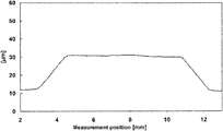
- FIG. 1 shows a plateau formed by the diffusion of a droplet into the material
- FIG. 2 shows a measured relief built up from two relief layers without immobilization
- FIG. 3 shows a measured relief built up from two relief layers with immobilization
- FIG. 4 shows a measured relief, experiment 1, diffusion through 1 mm perforated template
- FIG. 5 shows a measured relief, experiment 1, diffusion through 3 mm perforated template and
- FIG. 6 shows a measured relief, experiment 1, diffusion through 10 mm perforated template.
- the liquid applied to form the relief comprises at least one reactive monomer which, during the proposed process, diffuses into the substrate layer. Hardening, which immobilizes the reactive monomer, takes place only after the reactive monomer has been absorbed by the substrate layer. After hardening, no further diffusion of the reactive monomer takes place in the substrate layer.
- the result of penetration of the reactive monomer into the polymeric substrate layer is that, rather than build-up of the relief on the polymeric substrate layer, the polymeric substrate layer itself is raised and forms the relief, by virtue of the material that has diffused into same.
- the material of the relief is not provided solely by the liquid applied, or the reactive monomer, but instead the relief, or any individual relief layer, is built up by a mixture of material of the polymeric substrate layer with the reactive monomer.
- the material of the relief therefore derives from the combination of the reactive monomer present in the liquid with the material of the polymeric substrate layer.
- the relief is built up layer-by-layer, and the number of layers used here for the relief depends on the height of each relief layer and on the desired total height, or desired depth, of the relief.
- the depth of the relief here depends on the intended use of the printing plate.
- Flexographic printing uses relief printing plates with a relief depth in the range from 300 ⁇ m to 3000 ⁇ m. Relief depth for the printing of flexible packaging is from 300 ⁇ m to 700 ⁇ m.
- Other applications for example, in the electronics sector, where conductive structures are produced on a circuit board or other substrate, require relief printing plates with a relief depth in the range from 10 ⁇ m to 100 ⁇ m.
- each individual relief layer here represents a horizontal section through the entire relief.
- the liquid is applied in accordance with an image to the surface in a manner that produces an application pattern prescribed by the required relief.
- the application pattern can by way of example be obtained in that horizontal sections through the geometry of the required relief are determined; the application pattern for a required relief layer here is determined via the disposition of the horizontal section through the geometry of the relief in the appropriate height or relief depth.
- the thicknesses of all of the relief layers here can be identical or different, as required in a particular variant of process. By way of example, it is possible to reduce the thickness of a relief layer as relief depth increases. Equally, it is conceivable to vary the properties of the relief layers with increasing relief depth via use of a different liquid which by way of example comprises a different reactive monomer.
- the application of the liquid is followed by the diffusion of the reactive monomer into the polymeric substrate layer for a prescribed exposure time.
- the exposure time is typically in the range from 10 seconds to 3600 seconds.
- the exposure time here depends on the velocity of diffusion of the reactive monomer into the polymeric substrate layer, i.e. depends on the speed with which the polymeric substrate layer absorbs the reactive monomer.
- the diffusion velocity depends in turn on the reactive monomer used and on the material used for the polymeric substrate layer. Since the material of the relief is not intended to consist solely of the reactive monomer, it is preferable that the prescribed exposure time is such that, after expiry of the exposure time, the substrate layer has absorbed the reactive monomer applied.
- the reactive monomer is considered here to have been absorbed by the substrate layer if, after expiry of the exposure time, the quantity of reactive monomer still present on the surface of the polymeric substrate layer is less than 10% of the quantity applied. It is particularly preferable that, after expiry of the exposure time, the applied liquid and, respectively, the reactive monomer have been completely absorbed, and therefore no reactive monomer remains on the surface of the substrate layer.
- the material of the relief is therefore formed from the material of the substrate layer and from the reactive monomer that has diffused into the substrate layer.
- the thickness of a relief layer accordingly depends on the diffusion velocity of the reactive monomer in the material of the substrate layer and the exposure time, and where appropriate on the quantity of the liquid applied and, respectively, the quantity of the reactive monomer applied.
- the diffusion velocity of the reactive monomer in the substrate layer moreover influences the shape of the sides of the relief and, respectively, of a relief layer.
- the reason for this is that diffusion takes place not only in a direction perpendicular to the surface of the substrate layer but also in directions in the plane of the substrate layer. Steep sides are obtained when diffusion velocity is low and exposure times are short. The steepness of the sides decreases as exposure time increases and as diffusion velocities increase.
- For the uppermost relief layers which are applied last it is therefore preferable to select a reactive monomer with lower diffusion velocity than for the lower relief layers which are applied first.
- exposure time selected for the uppermost relief layers which are applied last is shorter than for the lower layers of relief that are applied first. The replication sharpness is thus increased in the relief, but at the same time the time required for build-up of the entire relief is minimized.
- a reactive monomer with high diffusion velocity in the polymeric substrate layer is used first, and subsequently a different reactive monomer with a lower diffusion velocity in the polymeric substrate layer is used. It is thus possible, with an essentially identical exposure time for each of the relief layers, to begin by producing relatively thick layers, so that build-up of the entire relief is achieved as rapidly as possible. The reactive monomer is then changed to one with lower diffusion velocity for the more externally situated layers, in order to permit more precise replication of the desired image in the relief.
- step c After application of the liquid comprising at least one reactive monomer and after expiry of the prescribed exposure time, hardening of the relief takes place in step c).
- the reactive monomer forms a three-dimensional network with the polymer of the substrate layer, and no further diffusion of the reactive monomer can occur in the substrate layer.
- the exposure parameters required for hardening are typically dependent on the reactive monomer used and on any photoinitiators used.
- the hardening can by way of example be achieved via exposure to heat or radiation. It is preferable to use reactive monomers in combination with photoinitiators where these can be hardened via exposure to electromagnetic radiation, in particular to ultraviolet light. It is preferable here that the photoinitiators are present in the substrate layer, rather than being added to the liquid.
- UV light is in the range from 100 nm to 400 nm. Particular preference is given here to reactive monomers which can be hardened via exposure to UVA radiation.
- the wavelength of UVA radiation is in the range from 320 nm to 400 nm. Any stickiness of the surface of the relief printing plate can then be eliminated by further hardening with UVC radiation.
- the wavelength of UVC radiation is in the range from 100 to 280 nm.
- UV light source provided for hardening, in particular a light source radiating in the UVA region.
- the UV light source can take the form of an LED (light-emitting diode) strip that is moved relative to the carrier in order to cover the entire surface thereof.
- the steps a) to c) are implemented once. Preference is given here to single application of the liquid to the surface of the substrate layer in the step a). The application of the liquid in step a) is followed by the steps b) and c) in this sequence, so that the reactive monomer applied with the liquid diffuses into the substrate layer, and the relief, comprising the reactive monomer and comprising the material of the polymeric substrate layer, is then hardened.
- the steps a) and b) are implemented from 2 to 100 times, and in each case here a step of diffusion into the material follows a step of application of the liquid, and hardening in step c) takes place after the final implementation of the step b).
- the hardening in step c) is also executed after every nth implementation of the steps a) and b), where n is a natural number and is from 2 to 10.
- the additional execution of the hardening in step c) here represents intermediate hardening which hardens and thus immobilizes the reactive monomer which has diffused into the polymeric substrate layer, thus suppressing any further diffusion, in the material of the polymeric substrate layer, of the reactive monomer that has already diffused into the material.
- Hardening here is preferably achieved in the same manner as the hardening provided after the application of all of the relief layers.
- the application of the liquid in step a) can be achieved by any process which permits application of a liquid in accordance with an image, or structured application of a liquid, to a surface.
- the application structure here corresponds to the image to be replicated on the relief.
- a layer of the reactive liquid it is possible, by way of example, for the application of a layer of the reactive liquid, to apply a mask to the surface of the polymeric substrate layer, where the mask protectively covers those regions of the surface of the substrate layer to which no liquid is to be applied.
- the liquid is applied to the entire surface, whereupon the liquid reaches the surface of the polymeric substrate layer through the mask, and then the mask is removed. Removal of the mask here can take place directly after application of the liquid or only after expiry of the prescribed exposure time.
- Application to the entire surface can by way of example be achieved in that the carrier together with the mask applied on the polymeric substrate layer is drawn through a liquid bath or immersed in a liquid bath.
- application of the reactive liquid to the entire surface of the substrate layer covered by the mask can be achieved via doctoring, spray-application, or by means of a suitable roll-application process.
- the liquid used in the process comprises at least one reactive monomer.
- the liquid can in particular also comprise a mixture of two or more different monomers.
- the liquid also optionally comprises a photoinitiator.
- Another term used for the liquid, by virtue of the reactive monomer present, is reactive liquid.
- the selection of the at least one reactive monomer in relation to the carrier used is preferably such that the diffusion velocity of the reactive monomer in the material of the polymeric substrate layer is in the range from 0.5 ⁇ m/min to 100 ⁇ m/min, preferably in the range from 2 ⁇ m/min to 50 ⁇ m/min.
- the diffusion velocity is usually temperature-dependent. It is preferable that the desired diffusion velocity of the reactive monomer in the material of the polymeric substrate layer is achieved at the temperature at which the liquid is applied to the surface of the substrate layer.
- the liquid is applied at a temperature in the range from 20 to 120° C.
- the boiling point of the reactive monomer imposes a natural upper limit on the application temperature.
- the maximal application temperature is usually below the boiling point of the reactive monomer.
- Reactive monomers can by way of example be ethylenically unsaturated compounds which can be cured by a free-radical route.
- the reactive monomers can also comprise epoxy functions or aziridine functions which can cure by a cationic mechanism.
- Preferred monomers have at least one polymerizable ethylenically unsaturated double bond.
- Very particularly preferred monomers are mono-, di- and triacrylates, and also -methacrylates.
- Suitable monomers are methyl methacrylate, ethyl acrylate, propyl (meth)acrylate, butyl (meth)acrylate, 2-ethylhexyl acrylate, lauryl acrylate, butanediol di(meth)acrylate, hexanediol di(meth)acrylate, nonanediol di(meth)acrylate, dodecanediol di(meth)acrylate, trimethylolpropane tri(meth)acrylate, hydroxyethyl (meth)acrylate, ethylene glycol (meth)acrylate, ethylene glycol di(meth)acrylate, tri- and tetraethylene glycol (meth)acrylates, glycerol di(meth)acrylate, propylene glycol mono- and di(meth)acrylates, trimethylolpropane tri(meth)acrylate, pentaerythritol tetra(meth)acryl
- Suitable reactive monomers can be glycidyl (meth)acrylate, phenyl glycidic ether (meth)acrylate, benzyl (meth)acrylate, cyclohexyl (meth)acrylate, isobornyl (meth)acrylate, dihydrodicyclopentadienyl (meth)acrylate, limonene (meth)acrylate, hexene (meth)acrylate, dimethylaminoethyl (meth)acrylate and bisphenol A diglycidic ether di(meth)acrylate.
- the following are also suitable: acrylamides and methacrylamides, for example hexamethylenebis(meth)acrylamide.
- Suitable fumarates are diethyl fumarate, dibutyl fumarate, dioctyl fumarate.
- suitable maleic acid derivatives are dibutyl maleate, dioctyl maleate, laurylmaleimide.
- polyester (meth)acrylates polyether (meth)acrylates, polyurethane (meth)acrylates, polybutadiene (meth)acrylates, polyisoprene (meth)acrylates.
- the acrylates and methacrylates can comprise further functional groups, for example amide groups, sulfonic ester groups or sulfonamide groups.
- Mixtures of a plurality of different monomers can, of course, also be used.
- monomers naturally also depends on the material of the polymeric carrier layer. If the process of the invention is to be used for build-up of nonpolar soft resilient flexographic printing plates, particularly preferred monomers are then ethylhexyl acrylate, hexanediol diacrylate, hexanediol dimethacrylate, dodecanediol diacrylate, dodecanediol dimethacrylate, cyclohexyl acrylate, cyclohexyl methacrylate, isobornyl acrylate, isobornyl methacrylate, and also dihydrodicyclopentadienenyl acrylate and the corresponding methacrylate.
- the proportion of the at least one reactive monomer present in the liquid is preferably from 50% by weight to 100% by weight, in particular preferably from 80% by weight to 100% by weight. It is very preferable that the reactive liquid comprises more than 90% by weight of monomer.
- the liquid can optionally also comprise further components.
- the further components are preferably selected from photoinitiators, plasticizers, emulsifiers, diffusion aids, solvents and surface-active substances.
- Surface-active substances can by way of example be used to control the wetting behavior of the liquid on the surface of the polymeric substrate layer.
- the liquid can optionally comprise a photoinitiator.
- the quantity of photoinitiator in the liquid can be from 0% by weight to 10% by weight.
- the carrier used is preferably composite material and typically comprises, alongside the polymeric substrate layer, a dimensionally stable carrier, for example a dimensionally stable carrier sheet such as a polyester sheet or a metal sheet such as aluminum or steel.
- a dimensionally stable carrier for example a dimensionally stable carrier sheet such as a polyester sheet or a metal sheet such as aluminum or steel.
- the carrier is a dimensionally stable cylinder sleeve.
- This type of intermediate layer can by way of example be an adhesion-promoting layer.
- PET Polyethylene terephthalate
- PBT polybutylene terephthalate
- PEN polyethylene naphthalate
- PC polycarbonate
- dimensionally stable cylinder sleeves that can be used are not only cylindrical polyester sleeves but also glass-fiber-reinforced polyester sleeves and other cylindrical carrier materials, for example nickel sleeves.
- the binder of the polymeric substrate layer is selected in essence in accordance with the requirements of the respective printing process.
- the process of the invention is not restricted to the flexographic printing process. If the intention is by way of example to produce hard relief printing plates which are used in the letterpress printing process or in the intaglio printing process, then hard polymers will be used as binders for the carrier layer, examples being polyvinyl alcohol, partially or highly hydrolyzed polyvinyl acetates or polyamides.
- Materials used as binders of the polymeric substrate layer for achieving the soft resilient properties of the printing plate that are typical for flexographic printing are preferably soft elastomeric materials.
- soft elastomeric materials examples include polybutadiene, polyisoprene, copolymers of butadiene and styrene, copolymers of isoprene and styrene, styrene-butadiene block copolymers, styrene-isoprene block copolymers, styrene-ethylene/butylene block copolymers, styrene/isoprene/butadiene/styrene block copolymers, ethylene-propylene-diene rubbers, silicone rubbers, natural rubbers, chloroprene rubbers, nitrile rubbers, polyisobutylene and soft resilient polyurethanes.
- thermoplastically processable elastomeric block copolymers comprise at least one block consisting essentially of alkenyl aromatics and at least one block consisting essentially of 1,3-dienes.
- the alkenyl aromatics can by way of example be styrene, ⁇ -methylstyrene or vinyltoluene. Preference is given to styrene.
- the 1,3-dienes are preferably butadiene and/or isoprene. These block copolymers can be linear, branched or radial block copolymers.
- thermoplastic-elastomer block copolymers are generally three-block copolymers of A-B-A type, but they can also be two-block polymers of A-B type, or block polymers having a plurality of alternating elastomeric and thermoplastic blocks, e.g. A-B-A-B-A. It is also possible to use mixtures of two or more different block copolymers. Commercially available three-block copolymers frequently comprise certain proportions of two-block copolymers. The diene units can have 1,2-linkages or 1,4-linkages. It is moreover also possible to use thermoplastic-elastomer block copolymers having terminal blocks made of styrene and having a random styrene-butadiene central block. Mixtures of a plurality of thermoplastic-elastomer block copolymers can, of course, also be used.
- thermoplastically processable elastomeric block copolymers which are partially fluorinated or perfluorinated or which incorporate fluorinated pendant chains. These polymers provide, to the substrate layer, an ink-repellent property which is advantageous during low-relief printing—in particular in applications in the electronics sector.
- the thermoplastic elastomeric material of the polymeric substrate layer preferably consists mainly of a polymer selected from poly(styrene-butadiene-styrene) (SBS), poly(styrene-isoprene-styrene) (SIS), ethylene-propylene-diene rubber (EPDM) and other SB block copolymers.
- SBS poly(styrene-butadiene-styrene)
- SIS poly(styrene-isoprene-styrene)
- EPDM ethylene-propylene-diene rubber
- Other materials with good suitability are poly(styrene-butadiene/styrene-styrene) block copolymers which are commercially available with the trademark Styroflex®.
- the total quantity of binders or polymers used in the polymeric substrate layer is usually from 50 to 100% by weight, based on the entirety of all of the constituents of the substrate layer, preferably from 50 to 90% by weight and particularly preferably from 60 to 85% by weight.
- the polymeric substrate layer comprises one or more photoinitiators.
- Suitable photoinitiators or photoinitiator systems comprise benzoin or benzoin derivatives, for example methylbenzoin or benzoin ethers, benzil derivatives, such as benzil ketals, acylarylphosphine oxides, acylarylphosphinic esters, polynuclear quinones, or benzophenones.
- the quantity of photoinitiator in the polymeric substrate layer is generally from 0.1 to 10% by weight, preferably from 1 to 5% by weight and particularly preferably from 1.5 to 3% by weight, based on the quantity (weight) of all of the constituents of the substrate layer.
- the liquid comprising the reactive monomer is free from photoinitiators. Because, after application to the surface of the substrate layer, the reactive monomer diffuses into same, and the photoinitiator is already present in the substrate layer, there is no need to add any photoinitiator to the liquid. Omission of photoinitiator in the liquid permits easier and safer handling of said liquid, because there is less risk of undesired hardening before application to the substrate layer.
- the material used for the polymeric substrate layer is preferably free from reactive monomers or comprises less than 10% by weight of reactive monomers. Since the reactive monomers diffuse, with the liquid, into the polymeric substrate layer, there is no requirement for the polymeric substrate layer to comprise reactive monomers. Minimized content of reactive monomers in the polymeric substrate layer is moreover advantageous because the properties of the resultant relief are then in essence determined by the binder or the material of the polymeric substrate layer.
- the polymeric substrate layer can optionally comprise one or more plasticizers.
- plasticizers comprise paraffinic, naphthenic or aromatic mineral oils, synthetic oligomers or resins, for example oligostyrene, high-boiling-point esters, oligomeric styrene-butadiene copolymers, oligomeric ⁇ -methylstyrene/p-methylstyrene copolymers, liquid oligobutadienes, liquid polyisoprenes, in particular those with average molar mass from 500 to 5000 g/mol, and liquid oligomeric acrylonitrile-butadiene copolymers and oligomeric ethylene-propylene-diene copolymers.
- Preferred plasticizers comprise white oil, butadiene oil and paraffin oil.
- the quantity of all plasticizers in the polymeric substrate layer is generally from 1 to 50% by weight and preferably from 1 to 30% by weight.
- the quantity of the plasticizers also depends on the respective binder system. Quantities of plasticizer that have proven successful in relief printing plates based on a styrene-isoprene binder system are from 1 to 10% by weight. Quantities of plasticizer that have proven successful in relief printing plates based on a styrene-butadiene binder system are from 20 to 40% by weight.
- the polymeric substrate layer can optionally also comprise further additives, for example mineral fillers, pigments, dyes, or additional compressible materials.
- mineral fillers for example silicates and powdered quartz, which change the surface topography of the substrate layer and can influence ink transfer during printing.
- the compressibility of the substrate layer can be increased by adding hollow microspheres.
- the quantity of fillers is usually less than 50% by weight, preferably less than 20% by weight, based on all of the components of the polymeric substrate layer.
- the polymeric substrate layer can moreover comprise surface-active substances, for example waxes, silicone oils or fluorinated compounds.
- surface-active substances for example waxes, silicone oils or fluorinated compounds.
- it can be necessary to provide ink-repellent properties to the surface of the polymeric substrate layer. This is achieved by adding surface-active substances which diffuse to the surface of the polymeric substrate layer, where they form a hydrophobic, i.e. ink-repellent, protective film.
- the protective film should be permeable to the monomer, since otherwise no diffusion is possible, and no build-up of relief is possible.
- the proportion of surface-active substances in the polymeric substrate layer is usually less than 5% by weight, preferably less than 2% by weight.
- the top sheet On the surface of the polymeric substrate layer there is usually also a protective top sheet which is removed before use, i.e. before the reactive liquid is applied.
- PET sheets of thickness from preferably 50 ⁇ m to 150 ⁇ m again have good suitability.
- the top sheet can be provided with a release coating, or a siliconized top sheet can be used.
- the thickness of the polymeric substrate layer depends in essence on the particular application or on the desired relief height.
- the thickness of the polymeric substrate layer should generally be greater than the desired relief height.
- polymeric substrate layers of thickness from 0.1 mm to 1.0 mm can be used.
- Typical flexographic printing requires relief heights of from 0.3 mm to 3.0 mm.
- the thickness of the polymeric substrate layers should then correspondingly be at least 0.5 mm to 3.0 mm.
- substrate layers of even greater thickness, up to 6 mm, can be used.
- the polymeric substrate layer is produced either by casting from solution or from the melt via extrusion and calendering. Uniformity of layer thickness of the polymeric substrate layer across the width of the coating and the length of the coating is of decisive importance for the applications of the invention.
- the maximum layer thickness deviation for layer thicknesses below 1 mm should be plus/minus 10 ⁇ m. For layer thicknesses of from 1 mm to 3 mm, the layer thickness deviation should be at most plus/minus 15 ⁇ m.
- the diffusion velocity of the respective monomer or of the respective monomer mixture in the respective polymeric substrate material is determined experimentally before implementation of the invention. It is thus possible to predict the exposure time required for build-up of a desired relief height. If the intention is successive application of a plurality of relief layers, it is preferable also to determine how the diffusion velocity of the respective monomer changes when the polymeric substrate layer comprises monomer that has already diffused into the material. In the event of successive application of a plurality of relief layers, with intermediate curing, it is then preferable to determine the diffusion velocity experimentally on correspondingly prepared substrate layers which comprise monomer that has already diffused into the material, and which have been hardened. The diffusion velocity of a monomer usually decreases when diffusion takes place through a polymer network that has already been hardened.
- the device is preferably designed and/or configured to carry out the process described herein. Accordingly, features described for the purposes of the process apply correspondingly to the device, and the features described for the purposes of the device apply correspondingly to the process.
- the device comprises means for the application, in accordance with an image, of a reactive liquid to the surface of a carrier with a polymeric substrate layer, and also means for the hardening of the reactive liquid that has diffused into the carrier layer.
- the device is moreover configured to execute one of the processes described herein.
- the means for the hardening of the reactive liquid that has diffused into the material preferably take the form of a UV light source which can irradiate the surface of the carrier. It is particularly preferable that the UV light source takes the form of an LED strip which spans the width of the carrier and can be moved relative to the carrier.
- the device preferably moreover comprises means for the calculation of application patterns, where an application pattern prescribes those regions of the surface to which the reactive liquid is applied.
- Kraton KX405 linear styrene-butadiene-styrene block copolymer having 24% styrene content from Kraton.
- Styroflex 2G66 a styrene-butadiene/styrene-styrene block copolymer having 65% styrene content from Styrolution.
- Nordel IP4725P an EPDM rubber having 70% of ethylene, 25% of propylene and 5% of ethylidenenorbornene from Dow.
- Nisso PB1000 polybutadiene oil having >85% 1,2-vinyl content from Nippon Soda.
- Syloid ED50 amorphous silicon dioxide, average particle size about 8 ⁇ m, from Grace.
- HDDA hexanediol diacrylate
- HDMA2 hexanediol dimethacrylate
- EHA 2-ethylhexyl acrylate
- the polymeric substrate layers described in table 1 were produced as follows.
- the total thickness of the composite made of carrier sheet, polymeric substrate layer and top sheet was 1.8 mm. The composite was drawn off on a vacuum suction belt and, after cooling, cut to size to give individual sheets.
- Diffusion velocities were determined by, in each case, applying a macroscopic droplet of a monomer by means of a metering syringe (volume 50 ⁇ l) to a selected carrier material. The droplet was allowed to remain on the polymeric substrate layer for a defined exposure time. Excess monomer was then removed by rinsing with isopropanol, and the resultant relief was fixed by irradiation with UVA light (10 minutes of exposure to light from tubular, nyloflex FIII lamps from Flint Group). The surface was then irradiated with UVC light (nyloflex F III lamps) for a further 3 minutes in order to render the surface non-sticky, and a Perthometer was used to measure the resultant relief.
- UVA light 10 minutes of exposure to light from tubular, nyloflex FIII lamps from Flint Group
- FIG. 1 shows an example of measurement at a temperature of 30° C., based on a droplet, using HDDA as monomer and, as carrier material, the SIS-based carrier material from table 1. Diffusion time was 20 minutes. A resultant height of the relief of 20 ⁇ m can be determined from the plot.
- a 2 ⁇ l droplet of the same monomer mixture was then applied to the center of the resultant circular relief plateau, and again allowed to remain on the plate for precisely 2 minutes at 30° C.
- the plate was then again immersed in isopropanol and blow-dried.
- the plate was then irradiated for 10 minutes with UVA light and then for 3 minutes with UVC light (nyloflex F III lamps), and the resultant relief was fixed, and the surface was detackified.
- FIG. 2 shows the profile of the resultant relief, measured by a Perthometer. Two plateaus are discernible. The relief height of the first plateau is about 7 ⁇ m, and the relief height of the second plateau is higher, being about 10 ⁇ m. Diffusion of the monomer mixture into the substrate material into which monomer has already diffused therefore takes place more rapidly than into a substrate material comprising no monomer.
- FIG. 3 shows the corresponding Perthometer-measurement profile.
- the relief height of the first plateau is about 8 ⁇ m.
- the relief height of the second plateau is now smaller, being about 5 ⁇ m.
- the relief edges are significantly sharper.
- the monomers that have diffused into the material in the first stage are immobilized by the intermediate irradiation, and can no longer diffuse laterally; a steeper relief edge is thus formed.
- the monomers that have diffused into the material in the first stage crosslink with the polymeric binder of the carrier layer and form a three-dimensional network; subsequent diffusion is thus retarded.
- the holes in the template were filled with HDA2 at room temperature (22° C.). After a diffusion time of 60 minutes, the template was removed from the carrier layer. Excess monomer was removed by washing with isopropanol, and the relief plate was blow-dried with compressed air. The relief was then fixed by irradiation with UVA light (10 minutes, nyloflex F III lamp), and the surface was detackified by means of UVC irradiation (3 minutes, nyloflex F III lamp). A Perthometer was used to measure the resultant relief (see FIGS. 4, 5 and 6 ).
- the built-up spots had steep sides.
- the spot surfaces were level and uniform.
- the relief heights determined were 42 ⁇ m (10 mm spot), 42 ⁇ m (3 mm spot) and 40 ⁇ m (1 mm spot).
- the built-up spots had steep sides and a level, uniform surface. Relief height was greater because of the higher diffusion velocity.
- the relief heights were 108 ⁇ m (10 mm spot), 106 ⁇ m (3 mm spot) and 108 ⁇ m (1 mm spot).
- a compressible adhesive tape was then used to bond the relief printing plate to the cylinder of a flexographic printing machine, and alcohol-based ink was used for printing.
- Table 3 collates the printing parameters.
- Printout of all of the relief spots was uniform with the print setting selected. Each printed spot exhibited full coverage and no excessive squeeze edge.
- the diameters of the surface of the spots on the printing plate and in the printed image were determined microscopically at the start of printing and after 500 prints. Micro-Shore-A hardness was moreover measured on the surface of the spots (see Table 4).
- the diameters of the relief spots at the surface are in all cases smaller than the respective template hole diameter.
- the diameters of the printed spots are larger, by from 0.1 mm to 0.2 mm, than the spot diameters on the relief printing plate.
- This increase is typical of flexographic printing and can be attributed to squeeze effects relating to the low-viscosity flexographic printing ink.
- Micro-Shore-A hardness was determined on the larger relief spots. Again, these values were in the range typical for flexographic printing: 67 and 68 Shore A.
- the Micro-Shore-A hardness of the surface of a flexographic printing plate (nyloflex ACE 1.7 mm from Flint Group) subjected to standard prior art irradiation and leach-out procedures is 64.
- the experiment confirms that the diffusion process of the invention can achieve additive build-up of relief printing plates typically used in flexographic printing and that the process of the invention provides flexographic printing plates with the necessary softness and resilience and resistance to swelling.
Abstract
- a) single or multiple application of a liquid comprising at least one reactive monomer to the surface of the substrate layer,
- b) diffusion of the reactive monomer into the polymeric substrate layer for a prescribed exposure time and
- c) hardening of the relief,
where in step a) the liquid is applied in accordance with an image to the surface and where, after the prescribed exposure time of step b), any liquid that remains on the surface, having not diffused into the material, is removed from the surface, and in step c) the relief that is hardened comprises the polymer of the substrate layer and reactive monomer that has diffused into the material.
Description
- a) single or multiple application of a liquid comprising at least one reactive monomer to the surface of the polymeric substrate layer,
- b) diffusion of the reactive monomer into the polymeric substrate layer for a prescribed exposure time and
- c) hardening of the relief,
| TABLE 1 | |||||
| S-I-S block | S-B-S block | EPDM | S-B/S-S block | ||
| copolymer | copolymer | rubber | copolymer | ||
| Quintac 3621C | 85% | |||
| Kraton KX405 | 75% | |||
| Nordel IP 4725P | 75% | |||
| Styroflex 2G66 | 75 | |||
| BDK | ||||
| 5% | 5% | 5% | 5% | |
| Winog 70 | 10% | 20% | ||
| white oil | ||||
| Nisso PB 1000 | 20 | |||
| Hexamoll DINCH | ||||
| 20% | ||||
| TABLE 2 | ||||
| Diffusion velocity | ||||
| Polymer carrier layer | Monomer | in μm/min | ||
| S-I-S | HDDA | 0.7 | ||
| S-I-S | HDMA | 1.3 | ||
| S-I-S | EHA | 4.4 | ||
| S-B-S | HDDA | 2.2 | ||
| S-B-S | HDMA | 3.2 | ||
| S-B-S | EHA | 3.9 | ||
| S-S/B-S | HDDA | 1.7 | ||
| S-S/B-S | HDMA | — | ||
| S-S/B-S | EHA | 3.9 | ||
| EPDM | HDDA | — | ||
| EPDM | HDMA | — | ||
| EPDM | EHA | 2.0 | ||
| TABLE 3 | |||
| Printing machine | F&K FP 6S/8 | ||
| Substrate | PE sheet | ||
| Printing ink | Siegwerk NC4012 cyan | ||
| Viscosity of printing ink | 22 sec | ||
| Anilox roll | 460 l/cm, 3.5 g/cm3 | ||
| Adhesive tape | Lohmann 5.3 | ||
| Print velocity | 80 m/min | ||
| Print setting | +30 μm in relation to kiss print | ||
| TABLE 4 | ||
| |
||
| 1 |
3 |
10 mm | ||
| Upper spot diameter on printing | 0.74 mm | 2.55 mm | 9.40 mm |
| plate | |||
| Printed spot diameter | 0.82 mm | 2.73 mm | 9.62 mm |
| (start of printing) | |||
| Printed spot diameter | 0.80 mm | 2.75 mm | 9.58 mm |
| (end of printing) | |||
| Micro-Shore-A hardness | Not measurable | 68 | 67 |
Claims (22)
Applications Claiming Priority (4)
| Application Number | Priority Date | Filing Date | Title |
|---|---|---|---|
| EP15191051.0 | 2015-10-22 | ||
| EP15191051 | 2015-10-22 | ||
| EP15191051.0A EP3159740B1 (en) | 2015-10-22 | 2015-10-22 | Method for generative production of relief printing plates |
| PCT/EP2016/075378 WO2017068125A1 (en) | 2015-10-22 | 2016-10-21 | Method for the additive production of relief printing plates |
Publications (2)
| Publication Number | Publication Date |
|---|---|
| US20180304609A1 US20180304609A1 (en) | 2018-10-25 |
| US11498325B2 true US11498325B2 (en) | 2022-11-15 |
Family
ID=54360891
Family Applications (1)
| Application Number | Title | Priority Date | Filing Date |
|---|---|---|---|
| US15/769,560 Active 2037-01-13 US11498325B2 (en) | 2015-10-22 | 2016-10-21 | Method for the additive production of relief printing plates |
Country Status (5)
| Country | Link |
|---|---|
| US (1) | US11498325B2 (en) |
| EP (1) | EP3159740B1 (en) |
| JP (1) | JP6732903B2 (en) |
| CN (1) | CN108369372B (en) |
| WO (1) | WO2017068125A1 (en) |
Citations (20)
| Publication number | Priority date | Publication date | Assignee | Title |
|---|---|---|---|---|
| US4323636A (en) | 1971-04-01 | 1982-04-06 | E. I. Du Pont De Nemours And Company | Photosensitive block copolymer composition and elements |
| US4857434A (en) * | 1986-09-23 | 1989-08-15 | W. R. Grace & Co. | Radiation curable liquid (meth) acrylated polymeric hydrocarbon maleate prepolymers and formulations containing same |
| EP0332070A2 (en) | 1988-03-10 | 1989-09-13 | BASF Aktiengesellschaft | Process for the development of imagewise exposed flexoprinting plates |
| US5262275A (en) | 1992-08-07 | 1993-11-16 | E. I. Du Pont De Nemours And Company | Flexographic printing element having an IR ablatable layer and process for making a flexographic printing plate |
| EP0641648A1 (en) | 1993-09-03 | 1995-03-08 | Uri Adler | Method and apparatus for the production of photopolymeric printing plates |
| EP1170121A1 (en) | 2000-06-13 | 2002-01-09 | Agfa-Gevaert naamloze vennootschap | Direct-to-plate flexographic printing plate precursor |
| EP1239329A2 (en) | 2001-03-06 | 2002-09-11 | E.I. Du Pont De Nemours And Company | A process for making a flexographic printing plate and a photosensitive element for use in the process |
| US6641772B2 (en) | 1999-05-18 | 2003-11-04 | Creo Srl | Method of forming objects from thermosensitive composition |
| EP1428666A1 (en) | 2002-12-11 | 2004-06-16 | Agfa-Gevaert | Preparation of flexographic printing plates using ink jet recording |
| US20040131778A1 (en) | 2001-12-11 | 2004-07-08 | Bart Verhoest | Preparation of flexographic printing plates using ink jet recording |
| US20040161705A1 (en) * | 2003-02-18 | 2004-08-19 | Jianbing Huang | Flexographic printing plate with ink-repellent non-image areas |
| EP1552922A1 (en) | 2004-01-09 | 2005-07-13 | Kodak Polychrome Graphics, LLC | Ink-jet formation of flexographic printing plates |
| US20060054040A1 (en) * | 2004-09-16 | 2006-03-16 | Agfa-Gevaert | Curable jettable liquid for flexography |
| EP1637926A2 (en) * | 2004-09-16 | 2006-03-22 | Agfa-Gevaert | Curable jettable liquid for the production of a flexographic printing plate |
| US20070259474A1 (en) * | 2006-05-03 | 2007-11-08 | Korean Institute Of Machinery & Materials | Method for forming high-resolution pattern having desired thickness or high aspect ratio using deep ablation |
| US20080053326A1 (en) | 2006-08-29 | 2008-03-06 | Anderson Vreeland | Inkjet composite stereographic printing plate and method for producing such printing plate |
| EP2033778A1 (en) | 2007-09-10 | 2009-03-11 | Agfa Graphics N.V. | Method of making a flexographic printing sleeve forme |
| EP2199082A1 (en) | 2008-12-19 | 2010-06-23 | Agfa Graphics N.V. | Imaging apparatus and method for making flexographic printing masters |
| WO2012175525A1 (en) | 2011-06-21 | 2012-12-27 | Agfa Graphics Nv | A curable jettable fluid for making a flexographic printing master |
| WO2014095361A1 (en) | 2012-12-18 | 2014-06-26 | Agfa Graphics Nv | Method of preparing a flexographic printing master |
Family Cites Families (3)
| Publication number | Priority date | Publication date | Assignee | Title |
|---|---|---|---|---|
| JPH09109528A (en) * | 1995-10-17 | 1997-04-28 | Brother Ind Ltd | Method and apparatus for manufacture of letterpress stamp |
| DE10100514A1 (en) * | 2001-01-08 | 2002-07-11 | Basf Drucksysteme Gmbh | Process for the production of thermally cross-linked, laser-engravable flexographic printing elements |
| DE102010031527A1 (en) * | 2010-07-19 | 2012-01-19 | Flint Group Germany Gmbh | Process for the preparation of flexographic printing plates comprising the irradiation with UV LEDs |
-
2015
- 2015-10-22 EP EP15191051.0A patent/EP3159740B1/en active Active
-
2016
- 2016-10-21 CN CN201680072975.2A patent/CN108369372B/en active Active
- 2016-10-21 WO PCT/EP2016/075378 patent/WO2017068125A1/en active Application Filing
- 2016-10-21 JP JP2018520413A patent/JP6732903B2/en active Active
- 2016-10-21 US US15/769,560 patent/US11498325B2/en active Active
Patent Citations (22)
| Publication number | Priority date | Publication date | Assignee | Title |
|---|---|---|---|---|
| US4323636A (en) | 1971-04-01 | 1982-04-06 | E. I. Du Pont De Nemours And Company | Photosensitive block copolymer composition and elements |
| US4857434A (en) * | 1986-09-23 | 1989-08-15 | W. R. Grace & Co. | Radiation curable liquid (meth) acrylated polymeric hydrocarbon maleate prepolymers and formulations containing same |
| EP0332070A2 (en) | 1988-03-10 | 1989-09-13 | BASF Aktiengesellschaft | Process for the development of imagewise exposed flexoprinting plates |
| US5061606A (en) | 1988-03-10 | 1991-10-29 | Basf Aktiengesellschaft | Preparation of relief printing plates |
| US5262275A (en) | 1992-08-07 | 1993-11-16 | E. I. Du Pont De Nemours And Company | Flexographic printing element having an IR ablatable layer and process for making a flexographic printing plate |
| EP0641648A1 (en) | 1993-09-03 | 1995-03-08 | Uri Adler | Method and apparatus for the production of photopolymeric printing plates |
| US6641772B2 (en) | 1999-05-18 | 2003-11-04 | Creo Srl | Method of forming objects from thermosensitive composition |
| EP1170121A1 (en) | 2000-06-13 | 2002-01-09 | Agfa-Gevaert naamloze vennootschap | Direct-to-plate flexographic printing plate precursor |
| EP1239329A2 (en) | 2001-03-06 | 2002-09-11 | E.I. Du Pont De Nemours And Company | A process for making a flexographic printing plate and a photosensitive element for use in the process |
| US20040131778A1 (en) | 2001-12-11 | 2004-07-08 | Bart Verhoest | Preparation of flexographic printing plates using ink jet recording |
| EP1428666A1 (en) | 2002-12-11 | 2004-06-16 | Agfa-Gevaert | Preparation of flexographic printing plates using ink jet recording |
| US20040161705A1 (en) * | 2003-02-18 | 2004-08-19 | Jianbing Huang | Flexographic printing plate with ink-repellent non-image areas |
| EP1552922A1 (en) | 2004-01-09 | 2005-07-13 | Kodak Polychrome Graphics, LLC | Ink-jet formation of flexographic printing plates |
| US20060054040A1 (en) * | 2004-09-16 | 2006-03-16 | Agfa-Gevaert | Curable jettable liquid for flexography |
| EP1637926A2 (en) * | 2004-09-16 | 2006-03-22 | Agfa-Gevaert | Curable jettable liquid for the production of a flexographic printing plate |
| US20070259474A1 (en) * | 2006-05-03 | 2007-11-08 | Korean Institute Of Machinery & Materials | Method for forming high-resolution pattern having desired thickness or high aspect ratio using deep ablation |
| US20080053326A1 (en) | 2006-08-29 | 2008-03-06 | Anderson Vreeland | Inkjet composite stereographic printing plate and method for producing such printing plate |
| EP2033778A1 (en) | 2007-09-10 | 2009-03-11 | Agfa Graphics N.V. | Method of making a flexographic printing sleeve forme |
| EP2199082A1 (en) | 2008-12-19 | 2010-06-23 | Agfa Graphics N.V. | Imaging apparatus and method for making flexographic printing masters |
| US20110219973A1 (en) * | 2008-12-19 | 2011-09-15 | Agfa Graphics Nv | Imaging apparatus and method for making flexographic printing masters |
| WO2012175525A1 (en) | 2011-06-21 | 2012-12-27 | Agfa Graphics Nv | A curable jettable fluid for making a flexographic printing master |
| WO2014095361A1 (en) | 2012-12-18 | 2014-06-26 | Agfa Graphics Nv | Method of preparing a flexographic printing master |
Non-Patent Citations (3)
| Title |
|---|
| International Report On Patentability with Written Opinion and English Translation for International Application No. PCT/EP2016/075378, dated May 3, 2018. |
| International Search Report for PCT/EP2016/075378 dated Feb. 24, 2017. |
| Written Opinion of the International Searching Authority for PCT/EP2016/075378 dated Feb. 24, 2017. |
Also Published As
| Publication number | Publication date |
|---|---|
| CN108369372B (en) | 2021-06-01 |
| JP2018532620A (en) | 2018-11-08 |
| CN108369372A (en) | 2018-08-03 |
| US20180304609A1 (en) | 2018-10-25 |
| JP6732903B2 (en) | 2020-07-29 |
| EP3159740A1 (en) | 2017-04-26 |
| WO2017068125A1 (en) | 2017-04-27 |
| EP3159740B1 (en) | 2018-08-01 |
Similar Documents
| Publication | Publication Date | Title |
|---|---|---|
| US7036430B2 (en) | Method for producing a flexographic printing plate formed by inkjetted fluid | |
| JP5408938B2 (en) | Photosensitive element having reinforcing particles and method for making a printing form from this element | |
| US8066837B2 (en) | Processes and apparatus for producing photopolymerizable, cylindrical, continuous, seamless flexographic printing elements | |
| US9599902B2 (en) | Photopolymerisable layered composite for producing flexo printing elements | |
| CN100534802C (en) | Printing sleeve with an integrated printing surface | |
| US8288080B2 (en) | Photopolymerizable flexographic printing elements and hard flexographic printing formes which are produced therefrom | |
| JP7458471B2 (en) | Original plate for flexo printing plate | |
| US20060249239A1 (en) | Method for the production of photopolymerizable, cylindrical, continuous seamless flexographic printing elements, and use thereof for the production of cylindrical flexographic printing forms | |
| JP5491125B2 (en) | Method for producing a printing mold from a photopolymerizable element | |
| US11498325B2 (en) | Method for the additive production of relief printing plates | |
| EP2755087A1 (en) | Flexographic printing original plate and water-developable photosensitive resin laminate | |
| US10591821B2 (en) | Flexographic printing precursor and magnetic development of the same | |
| US10824072B2 (en) | Method for generative production of relief printing plates by monomer diffusion through an integral mask layer | |
| US9713919B2 (en) | Printing form precursor having elastomeric cap layer and a method of preparing a printing form from the precursor | |
| EP1228864B1 (en) | Method for making a printing plate | |
| JP7315731B2 (en) | Method for manufacturing an image relief structure |
Legal Events
| Date | Code | Title | Description |
|---|---|---|---|
| FEPP | Fee payment procedure |
Free format text: ENTITY STATUS SET TO UNDISCOUNTED (ORIGINAL EVENT CODE: BIG.); ENTITY STATUS OF PATENT OWNER: LARGE ENTITY |
|
| AS | Assignment |
Owner name: FLINT GROUP GERMANY GMBH, GERMANY Free format text: ASSIGNMENT OF ASSIGNORS INTEREST;ASSIGNORS:FREUDENTHALER, EVA;TELSER, THOMAS;SIGNING DATES FROM 20180422 TO 20180423;REEL/FRAME:045820/0709 |
|
| STPP | Information on status: patent application and granting procedure in general |
Free format text: DOCKETED NEW CASE - READY FOR EXAMINATION |
|
| STPP | Information on status: patent application and granting procedure in general |
Free format text: NON FINAL ACTION MAILED |
|
| STPP | Information on status: patent application and granting procedure in general |
Free format text: RESPONSE TO NON-FINAL OFFICE ACTION ENTERED AND FORWARDED TO EXAMINER |
|
| STPP | Information on status: patent application and granting procedure in general |
Free format text: FINAL REJECTION MAILED |
|
| STPP | Information on status: patent application and granting procedure in general |
Free format text: ADVISORY ACTION MAILED |
|
| STPP | Information on status: patent application and granting procedure in general |
Free format text: DOCKETED NEW CASE - READY FOR EXAMINATION |
|
| STPP | Information on status: patent application and granting procedure in general |
Free format text: NON FINAL ACTION MAILED |
|
| STPP | Information on status: patent application and granting procedure in general |
Free format text: RESPONSE TO NON-FINAL OFFICE ACTION ENTERED AND FORWARDED TO EXAMINER |
|
| STPP | Information on status: patent application and granting procedure in general |
Free format text: FINAL REJECTION MAILED |
|
| STPP | Information on status: patent application and granting procedure in general |
Free format text: RESPONSE AFTER FINAL ACTION FORWARDED TO EXAMINER |
|
| STPP | Information on status: patent application and granting procedure in general |
Free format text: ADVISORY ACTION MAILED |
|
| STPP | Information on status: patent application and granting procedure in general |
Free format text: DOCKETED NEW CASE - READY FOR EXAMINATION |
|
| STPP | Information on status: patent application and granting procedure in general |
Free format text: NON FINAL ACTION MAILED |
|
| STPP | Information on status: patent application and granting procedure in general |
Free format text: RESPONSE TO NON-FINAL OFFICE ACTION ENTERED AND FORWARDED TO EXAMINER |
|
| STPP | Information on status: patent application and granting procedure in general |
Free format text: NOTICE OF ALLOWANCE MAILED -- APPLICATION RECEIVED IN OFFICE OF PUBLICATIONS |
|
| STPP | Information on status: patent application and granting procedure in general |
Free format text: PUBLICATIONS -- ISSUE FEE PAYMENT VERIFIED |
|
| STCF | Information on status: patent grant |
Free format text: PATENTED CASE |