US11495953B2 - Enclosure for cable distribution assembly - Google Patents
Enclosure for cable distribution assembly Download PDFInfo
- Publication number
- US11495953B2 US11495953B2 US17/072,875 US202017072875A US11495953B2 US 11495953 B2 US11495953 B2 US 11495953B2 US 202017072875 A US202017072875 A US 202017072875A US 11495953 B2 US11495953 B2 US 11495953B2
- Authority
- US
- United States
- Prior art keywords
- enclosure
- connectors
- hybrid
- assembly
- cable
- Prior art date
- Legal status (The legal status is an assumption and is not a legal conclusion. Google has not performed a legal analysis and makes no representation as to the accuracy of the status listed.)
- Active, expires
Links
Images


Classifications
-
- H—ELECTRICITY
- H02—GENERATION; CONVERSION OR DISTRIBUTION OF ELECTRIC POWER
- H02G—INSTALLATION OF ELECTRIC CABLES OR LINES, OR OF COMBINED OPTICAL AND ELECTRIC CABLES OR LINES
- H02G3/00—Installations of electric cables or lines or protective tubing therefor in or on buildings, equivalent structures or vehicles
- H02G3/02—Details
- H02G3/08—Distribution boxes; Connection or junction boxes
- H02G3/18—Distribution boxes; Connection or junction boxes providing line outlets
-
- G—PHYSICS
- G02—OPTICS
- G02B—OPTICAL ELEMENTS, SYSTEMS OR APPARATUS
- G02B6/00—Light guides; Structural details of arrangements comprising light guides and other optical elements, e.g. couplings
- G02B6/44—Mechanical structures for providing tensile strength and external protection for fibres, e.g. optical transmission cables
- G02B6/4401—Optical cables
- G02B6/4415—Cables for special applications
- G02B6/4416—Heterogeneous cables
-
- G—PHYSICS
- G02—OPTICS
- G02B—OPTICAL ELEMENTS, SYSTEMS OR APPARATUS
- G02B6/00—Light guides; Structural details of arrangements comprising light guides and other optical elements, e.g. couplings
- G02B6/44—Mechanical structures for providing tensile strength and external protection for fibres, e.g. optical transmission cables
- G02B6/4439—Auxiliary devices
- G02B6/4471—Terminating devices ; Cable clamps
-
- H—ELECTRICITY
- H02—GENERATION; CONVERSION OR DISTRIBUTION OF ELECTRIC POWER
- H02G—INSTALLATION OF ELECTRIC CABLES OR LINES, OR OF COMBINED OPTICAL AND ELECTRIC CABLES OR LINES
- H02G3/00—Installations of electric cables or lines or protective tubing therefor in or on buildings, equivalent structures or vehicles
- H02G3/02—Details
- H02G3/08—Distribution boxes; Connection or junction boxes
- H02G3/088—Dustproof, splashproof, drip-proof, waterproof, or flameproof casings or inlets
-
- H—ELECTRICITY
- H02—GENERATION; CONVERSION OR DISTRIBUTION OF ELECTRIC POWER
- H02G—INSTALLATION OF ELECTRIC CABLES OR LINES, OR OF COMBINED OPTICAL AND ELECTRIC CABLES OR LINES
- H02G9/00—Installations of electric cables or lines in or on the ground or water
- H02G9/02—Installations of electric cables or lines in or on the ground or water laid directly in or on the ground, river-bed or sea-bottom; Coverings therefor, e.g. tile
-
- H—ELECTRICITY
- H02—GENERATION; CONVERSION OR DISTRIBUTION OF ELECTRIC POWER
- H02G—INSTALLATION OF ELECTRIC CABLES OR LINES, OR OF COMBINED OPTICAL AND ELECTRIC CABLES OR LINES
- H02G3/00—Installations of electric cables or lines or protective tubing therefor in or on buildings, equivalent structures or vehicles
- H02G3/02—Details
- H02G3/04—Protective tubing or conduits, e.g. cable ladders or cable troughs
- H02G3/0493—Service poles
Definitions
- the present invention relates to an outdoor enclosure for receiving at least one input cable and for presenting multiple connectors. More particularly, the present invention is suitable for employment on an antenna tower, with an input cable extending up the tower and the connectors presenting fiber optic and/or power receptacles for receiving mating fiber optic and/or power connectors of tower-mounted equipment.
- embodiments of the invention are directed to an enclosure for breaking out a trunk cable, comprising: a base having a generally flat surface adapted for mounting to a mounting surface; a shell having a front and two side walls extending from opposite sides of the front and two opposed end walls, the side walls of the shell mounted to the base to form a cavity; a plurality of connectors mounted to each of the side walls; and a trunk cable routed into the cavity through one of the end walls, the trunk cable comprising a plurality of power conductors and/or a plurality of optical fibers.
- the power conductors and the optical fibers are connected with respective ones of the plurality of connectors.
- embodiments of the invention are directed to an assembly enclosure for breaking out a trunk cable, comprising: a base having a generally flat surface adapted for mounting to a mounting surface; a shell having a front and two side walls extending from opposite sides of the front and two opposed end walls, the side walls of the shell mounted to the base to form a cavity; a plurality of connectors mounted to each of the side walls; and a trunk cable routed into the cavity through one of the end walls, the trunk cable comprising a plurality of power conductors and/or a plurality of optical fibers; the power conductors and the optical fibers being connected with respective ones of the plurality of connectors; wherein each of the side walls is disposed at an oblique angle to the flat surface of the base. Each of the side walls is disposed at an oblique angle to the flat surface of the base.
- the front comprises a rounded profile that merges with the side walls.
- the front includes no connectors mounted thereon.
- embodiments of the invention are directed to an assembly enclosure for breaking out a trunk cable, comprising: a base having a generally flat surface adapted for mounting to a mounting surface; a shell having a front and two side walls extending from opposite sides of the front and two opposed end walls, the side walls of the shell mounted to the base to form a cavity; a plurality of connectors mounted to each of the side walls; and a trunk cable routed into the cavity through one of the end walls, the trunk cable comprising a plurality of power conductors and/or a plurality of optical fibers; the power conductors and the optical fibers being connected with respective ones of the plurality of connectors.
- the front comprises a flat surface on which connectors are mounted.
- FIG. 1 is a perspective view of an enclosure for distribution of the power conductors and optical fibers of a hybrid trunk cable according to embodiments of the invention that illustrates the definitions of directional terms.
- FIGS. 2-9 are various views of an enclosure according to alternative embodiments of the invention.
- FIGS. 10-17 are various views of an enclosure according to additional embodiments of the invention.
- FIGS. 18-25 are various views of the enclosure of FIG. 1 .
- FIGS. 26-32 are various views of an enclosure according to further embodiments of the invention.
- FIGS. 33-40 are various views of an enclosure according to still further embodiments of the invention.
- FIGS. 41-47 are various views of an enclosure according to yet further embodiments of the invention.
- FIGS. 48-54 are various view of an enclosure according to still further embodiments of the invention.
- FIGS. 55-59 are various views of an enclosure according to yet further embodiments of the invention.
- FIGS. 60-64 are various views of an enclosure according to still further embodiments of the invention.
- FIGS. 65-71 are various views of an enclosure according to yet further embodiments of the invention.
- FIGS. 72-76 are various views of an enclosure according to still further embodiments of the invention.
- FIGS. 77-83 are various views of an enclosure according to even further embodiments of the invention.
- FIGS. 84-88 are various views of an enclosure according to still further embodiments of the invention.
- FIGS. 89-93 are various views of an enclosure according to even further embodiments of the invention.
- FIGS. 94 and 95 are enlarged section views of the enclosures of FIGS. 89 and 85 showing the mating of the base and cover.
- spatially relative terms such as “under”, “below”, “lower”, “over”, “upper”, “lateral”, “left”, “right” and the like, may be used herein for ease of description to describe one element or feature's relationship to another element(s) or feature(s) as illustrated in the figures. It will be understood that the spatially relative terms are intended to encompass different orientations of the device in use or operation in addition to the orientation depicted in the figures. For example, if the device in the figures is inverted, elements described as “under” or “beneath” other elements or features would then be oriented “over” the other elements or features. The device may be otherwise oriented (rotated 90 degrees or at other orientations) and the descriptors of relative spatial relationships used herein interpreted accordingly.
- the present invention offers a series of designs for enclosures, which may be formed by an injection/thermal molding process, but not limited to such a process.
- enclosures may be well-suited for the transition of a cable (such as a hybrid power/fiber cable, which has multiple power conductors and multiple optical fibers to be distributed) to RRUs, antennas, and other electronic and/or communications equipment on the top of an antenna tower or similar structure.
- the enclosure moves away from the prior use of a base enclosure mounted to a support and lid mounted to the base enclosure.
- enclosures according to embodiments of the present invention essentially flip or reverse the roles of the base and the lid, such that the enclosure is mounted to an apparatus or support via the lid (now a “base”).
- a base with a flat panel/surface is mounted to the support, and is covered by a shell, on which connectors are mounted.
- FIG. 1 shows the base 302 and shell 304 (labeled “front”) of an exemplary enclosure 300 , and also illustrates the spatial terms top, bottom, front, rear, right and left.
- the enclosures may optionally use hybrid (i.e., multi-media), power, or fiber connectors, which are more robust to the environment and allow for more vulnerable positioning, e.g., at places other than at the bottom of the enclosure.
- the connectors are connected to the power conductors and/or optical fibers of the trunk cable within the enclosure.
- Enclosures 100 (shown in FIGS. 2-9 ), 200 (shown in FIGS. 10-17 ), and 300 (shown in FIGS. 18-25 ) aim to make it as easy as possible to pull the enclosure, while attached to the trunk cable, up to the top of the tower.
- connectors 110 , 210 , 310 are on either side wall 106 , 206 , 306 of the shell 104 , 204 , 304 , with a curved and smooth front 112 , 212 , 312 and top 114 , 214 , 314 .
- top surface 114 , 214 , 314 there are three variations of the top surface 114 , 214 , 314 to make it easier to pull up the tower, e.g., to transition by and past any cross-beam of the tower, which contacts the top of the enclosure 100 , 200 , 300 .
- the base 102 , 202 , 302 (best seen in FIGS. 7, 15 and 23 ) is attached to a pole or other mounting apparatus after the enclosure is pulled up the tower.
- the enclosure 100 of FIGS. 2-9 has a fully rounded top 114 formed on the shell 104 .
- the enclosure 100 may have the shortest length, but makes the shell 104 longer than the base 102 , which may lead to a more expensive manufacturing process.
- the enclosure 200 of FIGS. 10-17 has a base 202 that is longer than the shell 204 and utilizes a half circle surface formed at the top 214 of the shell 204 .
- the enclosure 300 of FIGS. 1 and 18-25 is essentially a curved spearheaded surface on the top 314 of the shell 304 that allows for deflection as the enclosure 300 is pulled up the tower, but minimizes the length of the enclosure 300 .
- the enclosures 100 , 200 , 300 provide smooth, sleek surfaces that should not catch on obstacles. Further, the designs may be more aesthetically pleasing than a typical box-shaped enclosure of the prior art.
- the added curves at the front surfaces 112 , 212 , 312 and top surfaces 114 , 214 , 314 may help to decrease the wind load drag coefficient experienced by the enclosures 100 , 200 , 300 when mounted to the tower.
- the flat panel of the base 102 , 202 , 302 is mostly obstructed anyway, as it is the mount side of the enclosure 100 , 200 , 300 .
- FIGS. 1-25 are about 3.5′′ ⁇ 3′′ ⁇ 11′′.
- the enclosures 400 , 500 , 600 , 700 illustrated therein aim to minimize the enclosure footprint on the tower.
- the shape of the shell may be modified to a multitude of different shapes and attached to the base and mounted to the tower. Each of the different shell shapes has its pros and cons and may be selected by the technician to best fit the needs of the particular installation.
- all of the enclosures in FIGS. 26-55 can reduce or minimize enclosure size and provide good usability relative to the enclosures of the prior art.
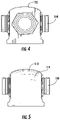
- the enclosure 400 shown therein has a generally triangular profile, with side walls 406 of the shell 404 meeting a very narrow front 412 .
- This arrangement can reduce space in such a way as to make the enclosure 400 narrower, which makes the enclosure easier to install, e.g., pull up the tower.
- the connectors 410 mounted to the side walls 406 are no longer disposed at 90 degrees to the base 402 ; instead, the side walls 406 and connectors 410 are at disposed at an oblique angle (e.g., between about 30 and 65 degrees relative to the flat surface of the base 402 , with a range of 55 to 60 being suitable for some embodiments), which can allow for more flexibility for the installation of jumper cables/cords in the connectors 410 , as the bends that need to be made in the jumper cordage may be less severe.
- the enclosure 400 may also decrease overall wind load, as the wind load coefficient may be lower due to the triangular shape.
- the enclosure 400 includes a relatively flat top 414 .
- the enclosure 500 of FIGS. 33-40 is similar to the enclosure 400 , but the front 512 of the shell 504 between the side walls 506 is wider and more gently curved.
- the base 502 is similarly wider.
- the enclosure 600 shown in FIGS. 41-47 takes the minimization a step further.
- the enclosure 600 is an even shorter structure, as it employs a trapezoidal shell 604 with side walls 606 and a flat front 512 , and it has a “3 ⁇ 2” array of connectors 610 rather than a “2 ⁇ 3” connector array configuration.
- the enclosure 600 has an increased width, potentially making it slightly less easy to pull up the tower and potentially increasing the wind load. However, once the enclosure 600 is mounted to the tower, the width may not be an issue, as the enclosure 600 has a very minimal footprint from its shell 604 and base 602 and the entire width may be covered by the surface of the tower supporting the enclosure.
- the trapezoidal shape of the shell 604 may also serve to decrease windload, due to the angled side surfaces and a reduction in height, which may also have a smaller wind drag coefficient. Furthermore, the smaller flat sidewalls 606 would also aid in decreasing windload.
- the larger mounting base 602 may be a negative factor for wind load; however, as the base 602 is mounted to the tower structure, this impact may be lower in some installations as the mounting surface of the structure can sometimes be larger than the mounting surface of the enclosure.
- the enclosure 700 shown therein has a shell 704 with side walls 706 and a front 712 in a generally square profile.
- the enclosure also has a “3 ⁇ 2” array of connectors 710 .
- the enclosure 700 maintains the short length of the enclosure 600 of FIGS. 41-47 , but minimizes the width. This may make the enclosure 700 a bit thicker in the direction from the base 702 to the front 712 .
- the squared design may also increase the difficulty to route jumper cables to the connectors 710 mounted on the side walls 706 and the front 712 of the enclosure 700 due to increased bend angles on the jumper cordage.
- Wind load may or may not be decreased relative to the enclosure 600 , as there is a negative tradeoff between the squared side walls 706 of the enclosure 700 versus the angled side walls 606 of the enclosure 600 , and a positive tradeoff in that the enclosure 700 is more compact, e.g., narrower side-to-side, as compared to the enclosure 600 .
- the enclosure 400 is about 10′′ ⁇ 4′′ ⁇ 4′′
- the enclosure 500 is about 10′′ ⁇ 6′′ ⁇ 4′′
- the enclosure 600 is about 6′′ ⁇ 4.5′′ ⁇ 2.5′′
- the enclosure 700 is about 6′′ ⁇ 3′′ ⁇ 3′′.
- the enclosures shown herein illustrate the input cable 50 (see FIG. 1 ) connected to the enclosure via a cable gland, there are other options, such as a trunk connector or connectors, molding over the cable, an epoxied nozzle, or other methods of integration.
- the concepts of the designs in may be extended to accommodate different numbers of RRUs (remote radio units) deployed upon the tower.
- the concepts could be extended to a 1 ⁇ 6 connector set-up, dependent on the number of RRUs supported, such as a hexagonal or octagonal shape. They can also be elongated to allow for additional RRU capacity.
- the enclosure 600 ′ FIGS.
- an enclosure 500 ′ (see FIGS. 60-64 ) has ten connectors 510 ′ distributed on two side walls 506 ′ that are longer than those of the enclosure 500 .
- the bottom end 818 of an enclosure 800 has a flat surface from which a nozzle 820 extends.
- a cable (not shown) is routed into the enclosure 800 through the nozzle 820 to be connected with the connectors 810 located on the exterior of the shell 804 .
- the flat surface of the bottom end 818 can provide a bearing surface against which a technician's fingers can press when the nozzle 820 and cable are grasped to support the enclosure.
- the nozzle 820 it can provide an ergonomic and intuitive place to support the enclosure 800 .
- the installer can wrap his hand around the nozzle 820 with the upper part of the hand/pointer finger resting on the flat bottom end 818 of the enclosure 800 .
- the cable entry port can also be moved to the center allowing flat flaps on all sides to support the weight of the enclosure 800 on the hand during installation. This also makes one-handed installation easier.
- the nozzle 820 on the bottom end 818 of the enclosure 800 : namely, that the nozzle 820 is located in the “corner” of the triangular bottom end 818 (see FIG. 68 ). Placement of the nozzle 820 in this location can facilitate assembly of the enclosure 820 .
- This placement means that the conductors in the hybrid cable need only slight manipulation for connection with the connectors 810 in the enclosure. With hybrid cable constantly increasing in size to higher and higher AWG cable, manipulating conductors in a small space and in short lengths can be very difficult. With this configuration, the cables rest on what is the “bottom” of the shell 804 during assembly where the shell 804 is flipped upside down.
- This arrangement can make it easier to splice or extend the conductors as well as simply route them to the connectors 810 if they are left whole. This arrangement also leaves more room for the assembler to route the optical fiber, as it can leave a large entire layer empty for fiber routing, which may be required/desirable in order not avoid overbending of the fiber.
- a drainage channel 930 is included below a vent 932 in the flat base 902 of the enclosure 900 .
- the vent 932 is included in the enclosure 900 to equalize the pressure in the enclosure 900 during temperature swings to alleviate stress on the joints.
- the entirety of the vent 932 is offset from the flat base 902 of the enclosure 900 (see FIG. 75 ) to protect it during installation.
- a rounded drainage surface 934 surrounds the vent 932 .
- the presence of the sloping channel 930 adjacent the vent 932 and in communication with the drainage surface 934 can ensure that water and debris can be conveyed away from the vent 932 in most orientations, including an orientation in which the flat base 902 of the enclosure 900 serves as the top surface (i.e. the orientation shown in FIG. 76 ).
- the sloped channel 930 can prevent ice build-up from pooled water. All these environmental factors can eventually damage or block the vent 932 from working. Only when the enclosure 900 is suspended upside down, with the cable extending upwardly, would the channel 930 not convey water and debris away from the vent 932 , and this orientation is impractical and therefore disfavored.
- an enclosure 1000 has a hexagonal profile with nine connectors 1010 such as that of the enclosure 600 ′ of FIGS. 55-59 , but also includes a nozzle 1020 and a flat bottom end 1018 as described above.
- a slightly differently version of a six-connector enclosure similar to the enclosure 800 of FIGS. 65-71 is shown in FIGS. 84-88 at 1100 .
- a slightly different version similar to the nine-connector enclosure 1000 of FIGS. 77-83 is shown at 1200 in FIGS. 89-93 .
- FIG. 94 a partial section view of the enclosure 1200 of FIGS. 89-93 illustrates that the lower end of the shell 1204 includes a thicker section 1254 from which an inner lip 1256 and an outer lip 1258 depend (forming a groove 1260 therebetween).
- the upper end of the base 1202 includes a rim 1262 .
- the rim 1262 fits within the groove 1260 when the base 1202 and the shell 1204 are mated.
- the trapezoidal profile lacks a long flat section that would easy be compressed. Instead, a compressive force on the front of the shell 1204 is generally directed outwards towards the base 1202 .
- the thicker sections 1254 of the lower ends of the shell 1204 can withstand the outwardly-directed force described above.
- the presence of the inner and outer lips 1254 , 1256 and the rim 1262 provides both the base 1202 and the shell 1204 with a large surface area on which a sealing adhesive (such as epoxy) can bond. This arrangement also provides an extremely strong connection to conjoin the two pieces, creating a more solidified object through which any external forces can transfer.
- the inner lip 1256 can also prevent any epoxy spillover inside the enclosure 1200 during assembly and adds even more surface area to conjoin the two pieces.
- the epoxy can also provides a water tight seal.
- FIG. 95 shows a similar sealing arrangement for the enclosure 1100 of FIGS. 84-88 .
Abstract
Description
Claims (20)
Priority Applications (2)
| Application Number | Priority Date | Filing Date | Title |
|---|---|---|---|
| US17/072,875 US11495953B2 (en) | 2015-03-16 | 2020-10-16 | Enclosure for cable distribution assembly |
| US17/954,555 US20230088281A1 (en) | 2015-03-16 | 2022-09-28 | Enclosure for cable distribution assembly |
Applications Claiming Priority (7)
| Application Number | Priority Date | Filing Date | Title |
|---|---|---|---|
| US201562133936P | 2015-03-16 | 2015-03-16 | |
| US201562174951P | 2015-06-12 | 2015-06-12 | |
| US201562189425P | 2015-07-07 | 2015-07-07 | |
| US15/071,620 US9742176B2 (en) | 2015-03-16 | 2016-03-16 | Enclosure for cable distribution assembly |
| US15/670,484 US10263406B2 (en) | 2015-03-16 | 2017-08-07 | Enclosure for cable distribution assembly |
| US16/376,255 US10819096B2 (en) | 2015-03-16 | 2019-04-05 | Enclosure for cable distribution assembly |
| US17/072,875 US11495953B2 (en) | 2015-03-16 | 2020-10-16 | Enclosure for cable distribution assembly |
Related Parent Applications (1)
| Application Number | Title | Priority Date | Filing Date |
|---|---|---|---|
| US16/376,255 Continuation US10819096B2 (en) | 2015-03-16 | 2019-04-05 | Enclosure for cable distribution assembly |
Related Child Applications (1)
| Application Number | Title | Priority Date | Filing Date |
|---|---|---|---|
| US17/954,555 Continuation US20230088281A1 (en) | 2015-03-16 | 2022-09-28 | Enclosure for cable distribution assembly |
Publications (2)
| Publication Number | Publication Date |
|---|---|
| US20210104881A1 US20210104881A1 (en) | 2021-04-08 |
| US11495953B2 true US11495953B2 (en) | 2022-11-08 |
Family
ID=56919302
Family Applications (5)
| Application Number | Title | Priority Date | Filing Date |
|---|---|---|---|
| US15/071,620 Active US9742176B2 (en) | 2015-03-16 | 2016-03-16 | Enclosure for cable distribution assembly |
| US15/670,484 Active US10263406B2 (en) | 2015-03-16 | 2017-08-07 | Enclosure for cable distribution assembly |
| US16/376,255 Active US10819096B2 (en) | 2015-03-16 | 2019-04-05 | Enclosure for cable distribution assembly |
| US17/072,875 Active 2036-05-17 US11495953B2 (en) | 2015-03-16 | 2020-10-16 | Enclosure for cable distribution assembly |
| US17/954,555 Pending US20230088281A1 (en) | 2015-03-16 | 2022-09-28 | Enclosure for cable distribution assembly |
Family Applications Before (3)
| Application Number | Title | Priority Date | Filing Date |
|---|---|---|---|
| US15/071,620 Active US9742176B2 (en) | 2015-03-16 | 2016-03-16 | Enclosure for cable distribution assembly |
| US15/670,484 Active US10263406B2 (en) | 2015-03-16 | 2017-08-07 | Enclosure for cable distribution assembly |
| US16/376,255 Active US10819096B2 (en) | 2015-03-16 | 2019-04-05 | Enclosure for cable distribution assembly |
Family Applications After (1)
| Application Number | Title | Priority Date | Filing Date |
|---|---|---|---|
| US17/954,555 Pending US20230088281A1 (en) | 2015-03-16 | 2022-09-28 | Enclosure for cable distribution assembly |
Country Status (6)
| Country | Link |
|---|---|
| US (5) | US9742176B2 (en) |
| EP (1) | EP3271974B1 (en) |
| CN (2) | CN107624208B (en) |
| AU (2) | AU2016233370B2 (en) |
| ES (1) | ES2888851T3 (en) |
| WO (1) | WO2016149337A1 (en) |
Families Citing this family (20)
| Publication number | Priority date | Publication date | Assignee | Title |
|---|---|---|---|---|
| CN107624208B (en) * | 2015-03-16 | 2020-04-14 | 康普技术有限责任公司 | Housing for a cable distribution assembly |
| CA3004328A1 (en) | 2015-11-11 | 2017-05-18 | Afl Telecommunications Llc | Optical connection terminals for fiber optic communications networks |
| WO2017120059A1 (en) | 2016-01-07 | 2017-07-13 | Commscope Technologies Llc | Flexible device for distributing hybrid cable and transitioning from trunk cable to jumper cable |
| USD825471S1 (en) | 2016-03-16 | 2018-08-14 | Commscope Technologies Llc | Cable breakout enclosure design |
| USD876364S1 (en) | 2016-03-16 | 2020-02-25 | Commscope Technologies Llc | Cable breakout enclosure |
| US10164389B2 (en) | 2016-09-26 | 2018-12-25 | Commscope Technologies Llc | Breakout enclosure for transitioning from trunk cable to jumper cable |
| US10355423B2 (en) | 2016-10-24 | 2019-07-16 | Commscope Technologies Llc | Hybrid connector assembly with integrated overvoltage protection |
| CN108152898A (en) * | 2016-12-06 | 2018-06-12 | 上海贝尔股份有限公司 | A kind of photoelectricity mixing junction box, photoelectricity Hybrid connections system and connection method |
| WO2018165081A1 (en) * | 2017-03-06 | 2018-09-13 | Commscope Technologies Llc | Modular monopole for wireless communications |
| US10209475B2 (en) | 2017-03-21 | 2019-02-19 | Commscope Technologies Llc | Modular breakout enclosure for transitioning from trunk cable to jumper cable |
| US9977211B1 (en) * | 2017-04-21 | 2018-05-22 | Afl Telecommunications Llc | Optical connection terminals for fiber optic communications networks |
| US10502915B2 (en) | 2017-06-29 | 2019-12-10 | Commscope Technologies Llc | Device for distributing trunk cable to jumper cable |
| EP3714300B1 (en) * | 2017-11-24 | 2023-10-25 | Prysmian S.p.A. | Electrical power and optical distribution box for fiber to the antenna systems |
| WO2019245778A1 (en) | 2018-06-19 | 2019-12-26 | Commscope Technologies Llc | Assembly for connecting connector with conduit |
| US20200136236A1 (en) * | 2018-10-29 | 2020-04-30 | Commscope Technologies Llc | Perforated door for monopole module and method of mounting same |
| USD901391S1 (en) | 2019-02-19 | 2020-11-10 | North American Interconnect L.L.C. | Distribution housing |
| US11677164B2 (en) * | 2019-09-25 | 2023-06-13 | Raycap Ip Assets Ltd | Hybrid antenna distribution unit |
| GB202016031D0 (en) * | 2020-10-09 | 2020-11-25 | Radio Design Ltd | Electrical connection apparatus, an electrical distribution system including electrical connection apparatus and a method of use thereof |
| US11493712B2 (en) * | 2021-04-06 | 2022-11-08 | Dell Products L.P. | Hybrid port to legacy port converter |
| CN113991569B (en) * | 2021-11-12 | 2024-02-23 | 国网河南省电力公司经济技术研究院 | Cable hidden type electric power and communication 5G sharing electric power steel pipe pole |
Citations (37)
| Publication number | Priority date | Publication date | Assignee | Title |
|---|---|---|---|---|
| US5938462A (en) | 1995-01-25 | 1999-08-17 | Haworth, Inc. | Modular communication cabling arrangement |
| US5984728A (en) | 1998-02-09 | 1999-11-16 | Apollo Resources & Developement Co., Ltd | Multi-socket electricity outlet having at least one circuit protection module |
| USD443248S1 (en) | 1999-10-18 | 2001-06-05 | Smc Kabushiki Kaisha | Signal-input device |
| US20050163448A1 (en) | 2004-01-27 | 2005-07-28 | Blackwell Chois A.Jr. | Multi-port optical connection terminal |
| US20050175307A1 (en) | 2004-02-06 | 2005-08-11 | Battey Jennifer A. | Optical connection closure having at least one connector port |
| US20050213921A1 (en) | 2004-03-08 | 2005-09-29 | Mertesdorf Daniel R | Fiber access terminal |
| US20060093303A1 (en) | 2004-11-03 | 2006-05-04 | Randy Reagan | Fiber drop terminal |
| US20060153516A1 (en) | 2005-01-13 | 2006-07-13 | Napiorkowski John J | Network interface device having integral slack storage compartment |
| USD538742S1 (en) | 2005-03-28 | 2007-03-20 | France/A Scott Fetzer Company | Transformer power supply for a gas discharge lamp |
| CN1981226A (en) | 2004-03-08 | 2007-06-13 | Adc电信公司 | Fiber access terminal |
| USD549656S1 (en) | 2006-04-26 | 2007-08-28 | Feng-Shen Hsiao | Socket assembly |
| CN101095072A (en) | 2004-11-03 | 2007-12-26 | Adc电信公司 | Fiber drop terminal |
| USRE40358E1 (en) | 1998-07-27 | 2008-06-03 | Adc Telecommunications, Inc. | Outside plant fiber distribution apparatus and method |
| US20080191831A1 (en) | 2007-02-09 | 2008-08-14 | Matyas Raymond T | Electrical power control outlet and system |
| US7477824B2 (en) | 2006-04-05 | 2009-01-13 | Adc Telecommunications, Inc. | Universal bracket for mounting a drop terminal |
| US20090134915A1 (en) | 2007-11-28 | 2009-05-28 | Shih-Ming Hwang | Signal converting apparatus with a relay function wire terminal |
| US7844158B2 (en) | 2007-10-09 | 2010-11-30 | Adc Telecommunications, Inc. | Mini drop terminal |
| US8275228B2 (en) | 2008-10-28 | 2012-09-25 | Commscope, Inc. Of North Carolina | Network interface unit for modular furniture |
| US20130084050A1 (en) | 2011-10-03 | 2013-04-04 | Kristof Vastmans | Aggregation enclosure for elevated, outdoor locations |
| WO2013063045A1 (en) | 2011-10-26 | 2013-05-02 | Corning Cable Systems Llc | Composite cable breakout assembly |
| US8532490B2 (en) | 2009-03-05 | 2013-09-10 | Adc Telecommunications, Inc. | Methods, systems and devices for integrating wireless technology into a fiber optic network |
| US8565571B2 (en) | 2009-07-21 | 2013-10-22 | Afl Telecommunications Llc | Modular, resealable fiber optic high fiber count packaging |
| US20140105539A1 (en) | 2010-04-14 | 2014-04-17 | Mark Edward Conner | Port mapping in fiber optic network devices |
| US8792767B2 (en) | 2010-04-16 | 2014-07-29 | Ccs Technology, Inc. | Distribution device |
| WO2014158369A1 (en) | 2013-03-29 | 2014-10-02 | 3M Innovative Properties Company | Modular breakout device for optical and electrical connections |
| US9078287B2 (en) | 2010-04-14 | 2015-07-07 | Adc Telecommunications, Inc. | Fiber to the antenna |
| US20150219856A1 (en) | 2014-02-06 | 2015-08-06 | Andrew Llc | Device for distributing hybrid cable and transitioning from trunk cable to jumper cable |
| US20160276817A1 (en) | 2015-03-16 | 2016-09-22 | Commscope Technologies Llc | Enclosure for cable distribution assembly |
| US9466962B1 (en) | 2014-07-01 | 2016-10-11 | Arlington Industries, Inc. | Rain tight electrical box assembly for mounting of an electrical fan or fixture |
| US20170141563A1 (en) | 2015-11-17 | 2017-05-18 | Commscope Technologies Llc | Device for distributing hybrid cable and transitioning from trunk cable to jumper cable with overvoltage protection |
| USD809406S1 (en) | 2016-05-31 | 2018-02-06 | Smc Corporation | Setting unit for pressure sensor with display |
| USD825471S1 (en) | 2016-03-16 | 2018-08-14 | Commscope Technologies Llc | Cable breakout enclosure design |
| USD875050S1 (en) | 2018-12-04 | 2020-02-11 | Chi-Wen Cheng | Socket |
| USD876364S1 (en) | 2016-03-16 | 2020-02-25 | Commscope Technologies Llc | Cable breakout enclosure |
| US20210091481A1 (en) | 2019-09-25 | 2021-03-25 | Raycap Ip Assets Ltd | Hybrid antenna distribution unit |
| USD924807S1 (en) | 2020-11-05 | 2021-07-13 | Chizhou Qinglianfeng Electronics Technology Co., Ltd | Power strip |
| USD931220S1 (en) | 2020-11-19 | 2021-09-21 | Guiming WANG | Power strip |
Family Cites Families (2)
| Publication number | Priority date | Publication date | Assignee | Title |
|---|---|---|---|---|
| DE10254055B4 (en) * | 2002-11-19 | 2006-10-26 | Deutsche Post Ag | System and method for the automated generation of printable data files |
| DE102010051319A1 (en) * | 2010-11-13 | 2012-05-16 | Mahle International Gmbh | Piston for an internal combustion engine |
-
2016
- 2016-03-16 CN CN201680028436.9A patent/CN107624208B/en active Active
- 2016-03-16 CN CN202010184543.9A patent/CN111384691B/en active Active
- 2016-03-16 AU AU2016233370A patent/AU2016233370B2/en active Active
- 2016-03-16 ES ES16765637T patent/ES2888851T3/en active Active
- 2016-03-16 US US15/071,620 patent/US9742176B2/en active Active
- 2016-03-16 EP EP16765637.0A patent/EP3271974B1/en active Active
- 2016-03-16 WO PCT/US2016/022600 patent/WO2016149337A1/en unknown
-
2017
- 2017-08-07 US US15/670,484 patent/US10263406B2/en active Active
-
2019
- 2019-04-05 US US16/376,255 patent/US10819096B2/en active Active
-
2020
- 2020-10-16 US US17/072,875 patent/US11495953B2/en active Active
-
2021
- 2021-01-22 AU AU2021200449A patent/AU2021200449B2/en active Active
-
2022
- 2022-09-28 US US17/954,555 patent/US20230088281A1/en active Pending
Patent Citations (52)
| Publication number | Priority date | Publication date | Assignee | Title |
|---|---|---|---|---|
| US5938462A (en) | 1995-01-25 | 1999-08-17 | Haworth, Inc. | Modular communication cabling arrangement |
| US5984728A (en) | 1998-02-09 | 1999-11-16 | Apollo Resources & Developement Co., Ltd | Multi-socket electricity outlet having at least one circuit protection module |
| USRE40358E1 (en) | 1998-07-27 | 2008-06-03 | Adc Telecommunications, Inc. | Outside plant fiber distribution apparatus and method |
| USD443248S1 (en) | 1999-10-18 | 2001-06-05 | Smc Kabushiki Kaisha | Signal-input device |
| US20050163448A1 (en) | 2004-01-27 | 2005-07-28 | Blackwell Chois A.Jr. | Multi-port optical connection terminal |
| US20050175307A1 (en) | 2004-02-06 | 2005-08-11 | Battey Jennifer A. | Optical connection closure having at least one connector port |
| CN1981226A (en) | 2004-03-08 | 2007-06-13 | Adc电信公司 | Fiber access terminal |
| US20050213921A1 (en) | 2004-03-08 | 2005-09-29 | Mertesdorf Daniel R | Fiber access terminal |
| US7292763B2 (en) | 2004-03-08 | 2007-11-06 | Adc Telecommunications, Inc. | Fiber access terminal |
| CN101095072A (en) | 2004-11-03 | 2007-12-26 | Adc电信公司 | Fiber drop terminal |
| US7489849B2 (en) | 2004-11-03 | 2009-02-10 | Adc Telecommunications, Inc. | Fiber drop terminal |
| US20060093303A1 (en) | 2004-11-03 | 2006-05-04 | Randy Reagan | Fiber drop terminal |
| US7805044B2 (en) | 2004-11-03 | 2010-09-28 | Adc Telecommunications, Inc. | Fiber drop terminal |
| US20060153516A1 (en) | 2005-01-13 | 2006-07-13 | Napiorkowski John J | Network interface device having integral slack storage compartment |
| USD538742S1 (en) | 2005-03-28 | 2007-03-20 | France/A Scott Fetzer Company | Transformer power supply for a gas discharge lamp |
| US7477824B2 (en) | 2006-04-05 | 2009-01-13 | Adc Telecommunications, Inc. | Universal bracket for mounting a drop terminal |
| USD549656S1 (en) | 2006-04-26 | 2007-08-28 | Feng-Shen Hsiao | Socket assembly |
| US20080191831A1 (en) | 2007-02-09 | 2008-08-14 | Matyas Raymond T | Electrical power control outlet and system |
| US7844158B2 (en) | 2007-10-09 | 2010-11-30 | Adc Telecommunications, Inc. | Mini drop terminal |
| US20090134915A1 (en) | 2007-11-28 | 2009-05-28 | Shih-Ming Hwang | Signal converting apparatus with a relay function wire terminal |
| US8275228B2 (en) | 2008-10-28 | 2012-09-25 | Commscope, Inc. Of North Carolina | Network interface unit for modular furniture |
| US8532490B2 (en) | 2009-03-05 | 2013-09-10 | Adc Telecommunications, Inc. | Methods, systems and devices for integrating wireless technology into a fiber optic network |
| US8929740B2 (en) | 2009-03-05 | 2015-01-06 | Adc Telecommunications, Inc. | Methods, systems and devices for integrating wireless technology into a fiber optic network |
| US20140199079A1 (en) | 2009-03-05 | 2014-07-17 | Adc Telecommunications, Inc. | Methods, systems and devices for integrating wireless technology into a fiber optic network |
| US8565571B2 (en) | 2009-07-21 | 2013-10-22 | Afl Telecommunications Llc | Modular, resealable fiber optic high fiber count packaging |
| US20140105539A1 (en) | 2010-04-14 | 2014-04-17 | Mark Edward Conner | Port mapping in fiber optic network devices |
| US9078287B2 (en) | 2010-04-14 | 2015-07-07 | Adc Telecommunications, Inc. | Fiber to the antenna |
| US8792767B2 (en) | 2010-04-16 | 2014-07-29 | Ccs Technology, Inc. | Distribution device |
| CN104041066A (en) | 2011-10-03 | 2014-09-10 | 蒂科电子瑞侃有限公司 | Aggregation enclosure for elevated, outdoor locations |
| US20130084050A1 (en) | 2011-10-03 | 2013-04-04 | Kristof Vastmans | Aggregation enclosure for elevated, outdoor locations |
| US9106981B2 (en) | 2011-10-03 | 2015-08-11 | Tyco Electronics Uk Ltd | Aggregation enclosure for elevated, outdoor locations |
| US20130108227A1 (en) * | 2011-10-26 | 2013-05-02 | Mark Edward Conner | Composite cable breakout assembly |
| WO2013063045A1 (en) | 2011-10-26 | 2013-05-02 | Corning Cable Systems Llc | Composite cable breakout assembly |
| US9069151B2 (en) | 2011-10-26 | 2015-06-30 | Corning Cable Systems Llc | Composite cable breakout assembly |
| WO2014158369A1 (en) | 2013-03-29 | 2014-10-02 | 3M Innovative Properties Company | Modular breakout device for optical and electrical connections |
| US20150219856A1 (en) | 2014-02-06 | 2015-08-06 | Andrew Llc | Device for distributing hybrid cable and transitioning from trunk cable to jumper cable |
| US9466962B1 (en) | 2014-07-01 | 2016-10-11 | Arlington Industries, Inc. | Rain tight electrical box assembly for mounting of an electrical fan or fixture |
| US9742176B2 (en) * | 2015-03-16 | 2017-08-22 | Commscope Technologies Llc | Enclosure for cable distribution assembly |
| US20160276817A1 (en) | 2015-03-16 | 2016-09-22 | Commscope Technologies Llc | Enclosure for cable distribution assembly |
| US10263406B2 (en) | 2015-03-16 | 2019-04-16 | Commscope Technologies Llc | Enclosure for cable distribution assembly |
| US10819096B2 (en) | 2015-03-16 | 2020-10-27 | Commscope Technologies Llc | Enclosure for cable distribution assembly |
| US20170141563A1 (en) | 2015-11-17 | 2017-05-18 | Commscope Technologies Llc | Device for distributing hybrid cable and transitioning from trunk cable to jumper cable with overvoltage protection |
| USD944743S1 (en) | 2016-03-16 | 2022-03-01 | Commscope Technologies Llc | Cable breakout enclosure |
| USD825471S1 (en) | 2016-03-16 | 2018-08-14 | Commscope Technologies Llc | Cable breakout enclosure design |
| USD945373S1 (en) | 2016-03-16 | 2022-03-08 | Commscope Technologies Llc | Cable breakout enclosure |
| USD876367S1 (en) | 2016-03-16 | 2020-02-25 | Commscope Technologies Llc | Cable breakout enclosure |
| USD876364S1 (en) | 2016-03-16 | 2020-02-25 | Commscope Technologies Llc | Cable breakout enclosure |
| USD809406S1 (en) | 2016-05-31 | 2018-02-06 | Smc Corporation | Setting unit for pressure sensor with display |
| USD875050S1 (en) | 2018-12-04 | 2020-02-11 | Chi-Wen Cheng | Socket |
| US20210091481A1 (en) | 2019-09-25 | 2021-03-25 | Raycap Ip Assets Ltd | Hybrid antenna distribution unit |
| USD924807S1 (en) | 2020-11-05 | 2021-07-13 | Chizhou Qinglianfeng Electronics Technology Co., Ltd | Power strip |
| USD931220S1 (en) | 2020-11-19 | 2021-09-21 | Guiming WANG | Power strip |
Non-Patent Citations (9)
| Title |
|---|
| Australian Exam Report in Application 2016233370, dated Jun. 10, 2020, 4 pages. |
| Australian Exam Report in Application 2021200449, dated Feb. 24, 2022, 3 pages. |
| Canford Catkit Ethercon Stage Patchbox, [online], [retrieved on Sep. 24, 2019]. Retrieved from Internet, https://www.canford.eo.uk/Products/2009575/49-880_CANFORD-CATKIT-ETHERCON- -STAGE-PATCHBOX-4-way-4x-Ethercon-to-4x-Ethercon. |
| Chinese Office Action corresponding to Chinese Application No. 201680028436.9 dated May 23, 2019. |
| Chinese Office Action in Application 202010184543.9, dated Nov. 20, 2020, 14 pgs. |
| European Examination Report corresponding to European Application No. 16765637.0 dated Sep. 25, 2019. |
| European Search Report corresponding to European Application No. 16765637.0 dated Nov. 23, 2018. |
| PCT International Search Report and Written Opinion for corresponding PCT Application No. PCT/US2016/022600, dated Jun. 27, 2016. |
| PCT Notification Concerning Transmittal of International Preliminary Report on Patentability for corresponding PCT Application No. PCT/US2016/022600 dated Sep. 28, 2017. |
Also Published As
| Publication number | Publication date |
|---|---|
| US20230088281A1 (en) | 2023-03-23 |
| US10263406B2 (en) | 2019-04-16 |
| CN111384691A (en) | 2020-07-07 |
| US20160276817A1 (en) | 2016-09-22 |
| ES2888851T3 (en) | 2022-01-07 |
| AU2016233370B2 (en) | 2020-11-05 |
| WO2016149337A1 (en) | 2016-09-22 |
| CN107624208A (en) | 2018-01-23 |
| AU2021200449A1 (en) | 2021-02-25 |
| US9742176B2 (en) | 2017-08-22 |
| EP3271974A1 (en) | 2018-01-24 |
| AU2021200449B2 (en) | 2022-07-28 |
| AU2016233370A1 (en) | 2018-02-01 |
| EP3271974A4 (en) | 2018-12-26 |
| CN111384691B (en) | 2021-08-27 |
| US20210104881A1 (en) | 2021-04-08 |
| EP3271974B1 (en) | 2021-07-21 |
| US20190237953A1 (en) | 2019-08-01 |
| US10819096B2 (en) | 2020-10-27 |
| CN107624208B (en) | 2020-04-14 |
| US20170338637A1 (en) | 2017-11-23 |
Similar Documents
| Publication | Publication Date | Title |
|---|---|---|
| US11495953B2 (en) | Enclosure for cable distribution assembly | |
| US9857537B2 (en) | Device for distributing hybrid cable and transitioning from trunk cable to jumper cable | |
| US9535226B2 (en) | Modular breakout device for optical and electrical connections | |
| US8576569B2 (en) | Electronic devices having multi-purpose cowlings and co-axial cable grounding and fixture brackets | |
| AU2013234534B2 (en) | Environmentally sealed cable breakout assemblies | |
| US7393243B2 (en) | Angled patch panel with pitched connector alignment | |
| KR102122102B1 (en) | Terminal box for optical fiber and power line composite cable | |
| CN102870026A (en) | Rotatable routing guide and assembly for fiber optic cables | |
| US20140185992A1 (en) | Fiber optic module housing and fiber optic module | |
| KR102497929B1 (en) | Terminal Box For Optical Fiber and Power Line Composite Cable And Optical Fiber and Power Line Composite Cable | |
| US11435540B2 (en) | Cable management system for a splice enclosure, and a splice enclosure with a cable management system | |
| US7218833B2 (en) | Wireless communication system and apparatus | |
| US10804663B2 (en) | Swivel pivot connector adapter | |
| KR200359037Y1 (en) | Mini connector | |
| US20070140641A1 (en) | Dual-Optical Fiber Coupler Enclosure |
Legal Events
| Date | Code | Title | Description |
|---|---|---|---|
| FEPP | Fee payment procedure |
Free format text: ENTITY STATUS SET TO UNDISCOUNTED (ORIGINAL EVENT CODE: BIG.); ENTITY STATUS OF PATENT OWNER: LARGE ENTITY |
|
| STPP | Information on status: patent application and granting procedure in general |
Free format text: APPLICATION DISPATCHED FROM PREEXAM, NOT YET DOCKETED |
|
| STPP | Information on status: patent application and granting procedure in general |
Free format text: DOCKETED NEW CASE - READY FOR EXAMINATION |
|
| AS | Assignment |
Owner name: JPMORGAN CHASE BANK, N.A., NEW YORK Free format text: ABL SECURITY AGREEMENT;ASSIGNORS:ARRIS ENTERPRISES LLC;COMMSCOPE TECHNOLOGIES LLC;COMMSCOPE, INC. OF NORTH CAROLINA;REEL/FRAME:058843/0712 Effective date: 20211112 Owner name: JPMORGAN CHASE BANK, N.A., NEW YORK Free format text: TERM LOAN SECURITY AGREEMENT;ASSIGNORS:ARRIS ENTERPRISES LLC;COMMSCOPE TECHNOLOGIES LLC;COMMSCOPE, INC. OF NORTH CAROLINA;REEL/FRAME:058875/0449 Effective date: 20211112 |
|
| AS | Assignment |
Owner name: WILMINGTON TRUST, DELAWARE Free format text: SECURITY INTEREST;ASSIGNORS:ARRIS SOLUTIONS, INC.;ARRIS ENTERPRISES LLC;COMMSCOPE TECHNOLOGIES LLC;AND OTHERS;REEL/FRAME:060752/0001 Effective date: 20211115 |
|
| STPP | Information on status: patent application and granting procedure in general |
Free format text: NON FINAL ACTION MAILED |
|
| STPP | Information on status: patent application and granting procedure in general |
Free format text: RESPONSE TO NON-FINAL OFFICE ACTION ENTERED AND FORWARDED TO EXAMINER |
|
| STPP | Information on status: patent application and granting procedure in general |
Free format text: NOTICE OF ALLOWANCE MAILED -- APPLICATION RECEIVED IN OFFICE OF PUBLICATIONS |
|
| AS | Assignment |
Owner name: COMMSCOPE TECHNOLOGIES LLC, NORTH CAROLINA Free format text: ASSIGNMENT OF ASSIGNORS INTEREST;ASSIGNOR:WANG, CHI-MING;REEL/FRAME:060350/0154 Effective date: 20160329 |
|
| STPP | Information on status: patent application and granting procedure in general |
Free format text: PUBLICATIONS -- ISSUE FEE PAYMENT VERIFIED |
|
| STCF | Information on status: patent grant |
Free format text: PATENTED CASE |