US11495254B2 - Media non-contacting magnetic recording head - Google Patents
Media non-contacting magnetic recording head Download PDFInfo
- Publication number
- US11495254B2 US11495254B2 US17/184,549 US202117184549A US11495254B2 US 11495254 B2 US11495254 B2 US 11495254B2 US 202117184549 A US202117184549 A US 202117184549A US 11495254 B2 US11495254 B2 US 11495254B2
- Authority
- US
- United States
- Prior art keywords
- back plate
- magnetic media
- fillet
- data storage
- storage device
- Prior art date
- Legal status (The legal status is an assumption and is not a legal conclusion. Google has not performed a legal analysis and makes no representation as to the accuracy of the status listed.)
- Active
Links
- 238000013500 data storage Methods 0.000 claims abstract description 38
- 239000000725 suspension Substances 0.000 claims description 10
- 230000003746 surface roughness Effects 0.000 description 20
- IJGRMHOSHXDMSA-UHFFFAOYSA-N Atomic nitrogen Chemical compound N#N IJGRMHOSHXDMSA-UHFFFAOYSA-N 0.000 description 6
- 239000000203 mixture Substances 0.000 description 6
- 230000008901 benefit Effects 0.000 description 5
- 239000001307 helium Substances 0.000 description 5
- 229910052734 helium Inorganic materials 0.000 description 5
- SWQJXJOGLNCZEY-UHFFFAOYSA-N helium atom Chemical compound [He] SWQJXJOGLNCZEY-UHFFFAOYSA-N 0.000 description 5
- 239000002274 desiccant Substances 0.000 description 4
- 239000007789 gas Substances 0.000 description 4
- 239000002245 particle Substances 0.000 description 4
- 229910052757 nitrogen Inorganic materials 0.000 description 3
- 238000007789 sealing Methods 0.000 description 3
- QVGXLLKOCUKJST-UHFFFAOYSA-N atomic oxygen Chemical compound [O] QVGXLLKOCUKJST-UHFFFAOYSA-N 0.000 description 2
- 238000010586 diagram Methods 0.000 description 2
- 230000007613 environmental effect Effects 0.000 description 2
- 230000006870 function Effects 0.000 description 2
- 238000005259 measurement Methods 0.000 description 2
- 238000000034 method Methods 0.000 description 2
- 239000001301 oxygen Substances 0.000 description 2
- 229910052760 oxygen Inorganic materials 0.000 description 2
- 230000008569 process Effects 0.000 description 2
- 230000004044 response Effects 0.000 description 2
- 239000000758 substrate Substances 0.000 description 2
- 239000000853 adhesive Substances 0.000 description 1
- 230000001070 adhesive effect Effects 0.000 description 1
- 230000000712 assembly Effects 0.000 description 1
- 238000000429 assembly Methods 0.000 description 1
- 230000009286 beneficial effect Effects 0.000 description 1
- 230000008859 change Effects 0.000 description 1
- 238000003486 chemical etching Methods 0.000 description 1
- 238000004891 communication Methods 0.000 description 1
- 230000003247 decreasing effect Effects 0.000 description 1
- 230000001419 dependent effect Effects 0.000 description 1
- 230000000694 effects Effects 0.000 description 1
- 238000005516 engineering process Methods 0.000 description 1
- 238000005530 etching Methods 0.000 description 1
- 239000001257 hydrogen Substances 0.000 description 1
- 229910052739 hydrogen Inorganic materials 0.000 description 1
- 125000004435 hydrogen atom Chemical class [H]* 0.000 description 1
- 239000011261 inert gas Substances 0.000 description 1
- 230000010354 integration Effects 0.000 description 1
- 230000005285 magnetism related processes and functions Effects 0.000 description 1
- 230000007246 mechanism Effects 0.000 description 1
- 238000003825 pressing Methods 0.000 description 1
- 239000007787 solid Substances 0.000 description 1
- 238000004544 sputter deposition Methods 0.000 description 1
- 238000000992 sputter etching Methods 0.000 description 1
- 239000000126 substance Substances 0.000 description 1
- 238000003466 welding Methods 0.000 description 1
- 238000004804 winding Methods 0.000 description 1
Images


Classifications
-
- G—PHYSICS
- G11—INFORMATION STORAGE
- G11B—INFORMATION STORAGE BASED ON RELATIVE MOVEMENT BETWEEN RECORD CARRIER AND TRANSDUCER
- G11B5/00—Recording by magnetisation or demagnetisation of a record carrier; Reproducing by magnetic means; Record carriers therefor
- G11B5/48—Disposition or mounting of heads or head supports relative to record carriers ; arrangements of heads, e.g. for scanning the record carrier to increase the relative speed
- G11B5/488—Disposition of heads
- G11B5/4893—Disposition of heads relative to moving tape
-
- G—PHYSICS
- G11—INFORMATION STORAGE
- G11B—INFORMATION STORAGE BASED ON RELATIVE MOVEMENT BETWEEN RECORD CARRIER AND TRANSDUCER
- G11B15/00—Driving, starting or stopping record carriers of filamentary or web form; Driving both such record carriers and heads; Guiding such record carriers or containers therefor; Control thereof; Control of operating function
- G11B15/60—Guiding record carrier
- G11B15/62—Maintaining desired spacing between record carrier and head
- G11B15/64—Maintaining desired spacing between record carrier and head by fluid-dynamic spacing
-
- G—PHYSICS
- G11—INFORMATION STORAGE
- G11B—INFORMATION STORAGE BASED ON RELATIVE MOVEMENT BETWEEN RECORD CARRIER AND TRANSDUCER
- G11B25/00—Apparatus characterised by the shape of record carrier employed but not specific to the method of recording or reproducing, e.g. dictating apparatus; Combinations of such apparatus
- G11B25/06—Apparatus characterised by the shape of record carrier employed but not specific to the method of recording or reproducing, e.g. dictating apparatus; Combinations of such apparatus using web-form record carriers, e.g. tape
- G11B25/063—Apparatus characterised by the shape of record carrier employed but not specific to the method of recording or reproducing, e.g. dictating apparatus; Combinations of such apparatus using web-form record carriers, e.g. tape using tape inside container
-
- G—PHYSICS
- G11—INFORMATION STORAGE
- G11B—INFORMATION STORAGE BASED ON RELATIVE MOVEMENT BETWEEN RECORD CARRIER AND TRANSDUCER
- G11B5/00—Recording by magnetisation or demagnetisation of a record carrier; Reproducing by magnetic means; Record carriers therefor
- G11B5/008—Recording on, or reproducing or erasing from, magnetic tapes, sheets, e.g. cards, or wires
- G11B5/00813—Recording on, or reproducing or erasing from, magnetic tapes, sheets, e.g. cards, or wires magnetic tapes
-
- G—PHYSICS
- G11—INFORMATION STORAGE
- G11B—INFORMATION STORAGE BASED ON RELATIVE MOVEMENT BETWEEN RECORD CARRIER AND TRANSDUCER
- G11B5/00—Recording by magnetisation or demagnetisation of a record carrier; Reproducing by magnetic means; Record carriers therefor
- G11B5/02—Recording, reproducing, or erasing methods; Read, write or erase circuits therefor
-
- G—PHYSICS
- G11—INFORMATION STORAGE
- G11B—INFORMATION STORAGE BASED ON RELATIVE MOVEMENT BETWEEN RECORD CARRIER AND TRANSDUCER
- G11B5/00—Recording by magnetisation or demagnetisation of a record carrier; Reproducing by magnetic means; Record carriers therefor
- G11B5/127—Structure or manufacture of heads, e.g. inductive
- G11B5/31—Structure or manufacture of heads, e.g. inductive using thin films
- G11B5/3103—Structure or manufacture of integrated heads or heads mechanically assembled and electrically connected to a support or housing
Definitions
- Embodiments of the present disclosure generally relate to a head assembly of a data storage device.
- Tape data storage is a system for storing digital information on magnetic tape using digital recording. Tape storage media is more commonly packaged in cartridges and cassettes. A tape drive performs writing or reading of data in the cartridges or cassettes. A common cassette-based format is LTO, which comes in a variety of densities.
- Tape drives operate by using a tape head (i.e., magnetic recording head) to record and read back information from tapes by magnetic processes.
- the tape head comprises servo elements and data elements that are arranged in an array that is oftentimes referred to as a tape head array.
- Tape drives also have sensors as well as motors.
- the tape drive system has many moving parts such as a tape (i.e., magnetic media) that moves between two reels. In between the two reels, the tape rolls over numerous rollers guiding the tape to a reading or writing position in front of the head. When the tape comes into contact with the tape head, the tape may experience contact stress that may result in the wear and tear of the tape, resulting in decreased lifespan and lower reliability.
- a tape i.e., magnetic media
- the present disclosure generally relates to a head assembly of a data storage device.
- the data storage device may include magnetic media embedded in the device or magnetic media from an insertable cassette or cartridge (e.g., in an LTO drive), where the magnetic head assembly reads from and writes to the magnetic media.
- the magnetic media moves across the magnetic head assembly.
- the magnetic head assembly is spaced a distance from the magnetic media such that non-contact recording occurs between the magnetic head assembly and the magnetic media.
- the magnetic media is supported by either a back plate or an air film generated by one or more fillet edges of the back plate and the velocity of the magnetic media as the magnetic media moves across the magnetic head assembly.
- a data storage device comprises a magnetic recording head assembly configured to read from and write to a magnetic media, the assembly comprising a slider comprising one or more read elements and one or more write elements.
- the data storage device further comprises a back plate disposed adjacent to the slider, the back plate comprising a first surface having a roughness between about 5 nm and about 100 nm disposed at a media facing surface and one or more fillet edges disposed adjacent to the first surface.
- the magnetic media is disposed between the slider and the back plate.
- a data storage device comprises magnetic recording head assembly configured to read from and write to a magnetic media, the assembly comprising a load, a suspension coupled to the load, and a slider coupled to the suspension.
- the slider comprises one or more read elements and one or more write elements.
- the data storage device further comprises a back plate having one or more fillet edges disposed adjacent to the slider.
- the magnetic media is disposed between the slider and the back plate, the magnetic media comprising a first surface spaced a first distance from the slider and a second surface spaced a second distance from the back plate.
- the one or more fillet edges cause an air film to be disposed between the second surface of the magnetic media and the back plate, the air film supporting the magnetic media.
- the data storage device comprises a magnetic recording head assembly configured to read from and write to a magnetic media, the assembly comprising a slider comprising one or more read elements and one or more write elements.
- the data storage device further comprises a back plate having one or more right angle edges disposed adjacent to the slider.
- the magnetic media is disposed between the slider and the back plate.
- the magnetic media includes a first surface spaced a first distance from the slider and a second surface contacting the back plate.
- FIGS. 1A-1C illustrate a perspective exploded view and a simplified top down and side profile view of a tape embedded drive, in accordance with some embodiments.
- FIG. 2 illustrates a top perspective view of a printed circuit board assembly (PCBA) of the tape embedded drive, in accordance with some embodiments.
- PCBA printed circuit board assembly
- FIG. 3 illustrates a control block diagram for a servo-mechanical system of the tape embedded drive, in accordance with some embodiments.
- FIGS. 4A-4B illustrate an improved head assembly including a back plate, in accordance with some embodiments.
- FIGS. 4C-4G illustrate various fillet edges of the back plate of FIG. 4A , according to various embodiments.
- FIGS. 5A-5B illustrate a perspective view of a back plate, in accordance with some embodiments.
- the present disclosure generally relates to a head assembly of a data storage device.
- the data storage device may include magnetic media embedded in the device or magnetic media from an insertable cassette or cartridge (e.g., in an LTO drive), where the magnetic head assembly reads from and writes to the magnetic media.
- the magnetic media moves across the magnetic head assembly.
- the magnetic head assembly is spaced a distance from the magnetic media such that non-contact recording occurs between the magnetic head assembly and the magnetic media.
- the magnetic media is supported by either a back plate or an air film generated by one or more fillet edges of the back plate and the velocity of the magnetic media as the magnetic media moves across the magnetic head assembly.
- FIGS. 1A-1C illustrate a perspective exploded view and a simplified top down and side profile view of a tape embedded drive (TED) 100 , in accordance with some embodiments.
- the tape embedded drive comprises a casing 105 , one or more tape reels 110 , one or more motors (e.g., a stepping motor 120 (also known as a stepper motor), a voice coil motor (VCM) 125 , etc.) a head assembly 130 with one or more read heads and one or more write heads, and tape guides/rollers 135 a , 135 b .
- the term “head assembly” may be referred to as “magnetic recording head”, interchangeably, for exemplary purposes.
- the tape embedded drive further comprises a printed circuit board assembly (PCBA).
- PCBA printed circuit board assembly
- most of the components are within an interior cavity of the casing, except the PCBA, which is mounted on an external surface of the casing.
- the same components are illustrated in a perspective view in FIG. 1A .
- the term “tape” may be referred to as “magnetic media”, interchangeably, for exemplary purposes.
- the magnetic recording head assembly discussed herein is applicable to a data storage device such as a hard disk drive (HDD) as well as a tape drive such as a tape embedded drive (TED) or an insertable tape media drive.
- a data storage device such as a hard disk drive (HDD)
- TED tape embedded drive
- An example TED is described in co-pending patent application titled “Tape Embedded Drive,” application. Ser. No. 16/365,034, filed Mar. 31, 2019, assigned to the same assignee of this application.
- any reference in the detailed description to a HDD or tape drive is merely for exemplification purposes and is not intended to limit the disclosure unless explicitly claimed.
- reference to or claims directed to magnetic recording devices are intended to include both HDD and tape drive unless HDD or tape drive devices are explicitly claimed.
- aspects disclosed herein such as the magnetoresistive devices, may be used in magnetic sensor applications outside of HDD's and tape media drives such as TED's, such as spintronic devices other than HDD's and tape media drives.
- aspects disclosed herein may be used in magnetic elements in magnetoresistive random-access memory (MRAM) devices (e.g., magnetic tunnel junctions as part of memory elements), magnetic sensors or other spintronic devices.
- MRAM magnetoresistive random-access memory
- two tape reels 110 are placed in the interior cavity of the casing, with the center of the two tape reels on the same level in the cavity and with the head assembly 130 located in the middle and below the two tape reels.
- Tape reel motors located in the spindles of the tape reels can operate to wind and unwind the tape media 115 in the tape reels.
- Each tape reel may also incorporate a tape folder to help the tape media 115 be neatly wound onto the reel.
- the tape media may be made via a sputtering process to provide improved areal density.
- the tape media 115 comprises two surfaces, an oxide side and a substrate side.
- the oxide side is the surface that can be magnetically manipulated (written to or read from) by one or more read/write heads.
- the substrate side of the tape media 115 aids in the strength and flexibility of the tape media 115 .
- Tape media 115 from the tape reels are biased against the guides/rollers 135 a , 135 b (collectively referred to as guides/rollers 135 ) and are movably passed along the head assembly 130 by movement of the reels.
- the illustrated embodiment shows four guides/rollers 135 a , 135 b , with the two guides/rollers 135 a furthest away from the head assembly 130 serving to change direction of the tape media 115 and the two guides/rollers 135 b closest to the head assembly 130 by pressing the tape media 115 against the head assembly 130 .
- the guides/rollers 135 utilize the same structure.
- the guides/rollers 135 may have more specialized shapes and differ from each other based on function.
- a lesser or a greater number of rollers may be used.
- the two function rollers may be cylindrical in shape, while the two functional guides may be flat-sided (e.g., rectangular prism) or clip shaped with two prongs and the film moving between the prongs of the clip.
- the voice coil motor and stepping motor may variably position the tape head(s) transversely with respect to the width of the recording tape.
- the stepping motor may provide coarse movement, while the voice coil motor may provide finer actuation of the head(s).
- servo data may be written to the tape media to aid in more accurate position of the head(s) along the tape media 115 .
- the casing 105 comprises one or more particle filters 141 and/or desiccants 142 , as illustrated in FIG. 1A , to help maintain the environment in the casing.
- the particle filters may be placed where airflow is expected.
- the particle filters and/or desiccants may be placed in one or more of the corners or any other convenient place away from the moving internal components.
- the moving reels may generate internal airflow as the tape media winds/unwinds, and the particle filters may be placed within that airflow.
- the tape media 115 may not be exposed to the outside of the casing, such as in conventional tape drives.
- the tape media 115 does not need to be routed along the edge of the casing and can be freely routed in more compact and/or otherwise more efficient ways within the casing.
- the head(s) and tape reels may be placed in a variety of locations to achieve a more efficient layout, as there are no design requirements to provide external access to these components.
- the casing 105 comprises a cover 150 and a base 145 .
- the PCBA 155 is attached to the bottom, on an external surface of the casing 105 , opposite the cover 150 .
- the PCBA is made of solid state electronics, environmental issues are less of a concern, so it does not need to be placed inside the casing 105 . That leaves room inside casing for other components, particularly, the moving components and the tape media 115 that would benefit from a more protected environment.
- the tape embedded drive 100 is sealed. Sealing can mean the drive is hermetically sealed or simply enclosed without necessarily being airtight. Sealing the drive may be beneficial for tape film winding stability, tape film reliability, and tape head reliability. Desiccant may be used to limit humidity inside the casing.
- the cover 150 is used to hermetically seal the tape embedded drive.
- the drive 100 may be hermetically sealed for environmental control by attaching (e.g., laser welding, adhesive, etc.) the cover to the base 145 .
- the drive 100 may be filled by helium, nitrogen, hydrogen, or any other typically inert gas.
- a pre-amp for the heads may be added to the tape embedded drive.
- the pre-amp may be located on the PCBA 155 , in the head assembly 130 , or in another location. In general, placing the pre-amp closer to the heads may have a greater effect on the read and write signals in terms of signal-to-noise ratio (SNR).
- SNR signal-to-noise ratio
- some of the components may be removed. For example, the filters 141 and/or the desiccant 142 may be left out.
- FIG. 2 illustrates a top perspective view of a printed circuit board assembly (PCBA) 155 of the tape embedded drive 100 , in accordance with some embodiments.
- the PCBA 155 of the tape embedded drive may be the PCBA 155 of FIG. 1 .
- the PCBA 155 is attached to the bottom surface of the casing, with a connector 205 attaching to contacts or an interface on the bottom surface electrically/electronically connected to internal components in the casing.
- the contacts or interface may be electrically connected to one or more motors and/or actuators within the casing.
- the contacts/interface are built into the casing without comprising an air tight seal of the casing.
- the connector 205 may be an electrical feed-through electrically connecting components inside the casing to those on the PCBA, while maintaining sealing of the casing.
- the PCBA 155 can include various components, such as one or more controllers, one or more connectors 205 , a system on a chip (SoC) 210 , one or more data interfaces 215 (e.g., Serial ATA (SATA), Serial Attached SCSI (SAS), non-volatile memory express (NVMe), or the like), a memory 220 , a Power Large Scale Integration (PLSI) 225 , and/or data read channel controller 230 .
- One or more cutouts 235 can be added in the PCBA 155 to provide additional space for tape reel motors, if needed. For example, the portion of the casing above the tape reel motors may be raised to provide additional space for the motors. By providing cutouts 235 , the thickness of the tape embedded drive 100 may be reduced as the PCBA 155 may surround the raised portion of the casing.
- the PCBA 155 may extend along the entire bottom exterior surface of the casing 105 or may only partially extend along the surface, depending on how much space the various components need.
- a second PCBA 155 may be located internally in the casing 105 and be in communication with the first PCBA 155 , for example, via the connector 205 .
- a controller on the PCBA 155 controls the read and write operations of the tape embedded drive 100 .
- the controller may engage the tape spool motors and cause the tape spools to wind the tape film forwards or backwards.
- the controller may use the stepping motor and the voice coil motor to control placement of the head(s) over the tape film.
- the controller may also control output/input of data to or from the tape embedded drive 100 through the one or more interfaces 215 , such as SATA or SAS.
- the tape embedded drive 100 may use other form factors. For example, if tape technology become sufficiently miniaturized in the future, then the tape embedded drive could use a 2.5 inch drive form factor, like that used by laptop HDDs. In some embodiments, where larger sizes are desired, the tape embedded drive 100 may use a 5.25 inch drive form factor for the casing, such as those used by computer CD-ROMs. Furthermore, the tape embedded drive 100 may use the 3.5 inch form factor with some variations. For example, the drive may be slightly longer/shorter, slightly thicker/thinner, or the like. Even with slight differences in dimensions or placement of data/power interfaces, the drive 100 may still be compatible with existing 3.5 inch drive form factor based infrastructure found in various computer equipment, such as racks and servers.
- FIG. 3 illustrates a control block diagram for a servo-mechanical system, such as an actuator system 300 , of the tape embedded drive 100 , in accordance with some embodiments.
- the control logic for the system may be implemented as a process in one or more controllers of the tape embedded drive 100 , such as the SoC and/or PLSI in the PCBA and used to control one or more motors and/or one or more actuators.
- a stepping motor controller 305 work together to control a stepping motor 315 , a PZT actuator 320 , and a VCM 325 to coordinate the movement of the head(s) in response to a target command.
- the stepping motor 315 may provide coarse movement
- the VCM 325 may provide fine movement
- the PZT actuator 320 may provide very fine movement.
- the stepping motor stroke may be about 12.65 mm, with the VCM stroke at about 4 mm, and the PZT stroke at about 4 ⁇ m.
- the various strokes creates a movement ratio of about 30,000:10,000:1 (stepping motor:VCM:PZT actuator). In other embodiments, the ratios may be different based on the performance specifications of the motors and the actuators.
- a first control signal 330 is sent from the stepping motor controller to the stepping motor.
- the head(s) are then moved in a coarse movement.
- a head position sensor detects the position of the head(s) after the first movement and provides a positive error signal (PES) to the VCM and PZT controllers.
- PES positive error signal
- the VCM and the PZT controllers may further move the head(s) in a fine and a very fine movement, respectively, if needed, to place the head(s) into the desired position.
- a first amplifier 333 may be positioned in between the PZT controller 307 and the PZT actuator 320 to amplify a second control signal 335 .
- a second amplifier 338 may be positioned in between the VCM controller 310 and the VCM 325 to amplify a third control signal 340 .
- the PZT actuator 320 and the VCM 325 move the head(s) serially.
- the VCM first moves the head(s) and then, if the head(s) are within a first threshold distance from the target position, the PZT actuator 320 may take over the movement of the head(s) for very fine movements.
- the PZT actuator 320 and the VCM 325 may move the head(s) in parallel. It should be noted that although PZT is used throughout in the description of the control system of FIG. 3 , as disclosed above, other types of actuators may be used in place of PZTs, and the system of FIG. 3 may be adapted accordingly in other embodiments.
- FIGS. 4A and 4B illustrate magnetic recording head assemblies 400 , 450 , respectively, comprising back plates, in accordance with some embodiments.
- Each magnetic recording head assembly 400 , 450 comprises a magnetic recording head including a load 402 , a suspension 404 coupled to the load 402 , and a slider 406 coupled to the suspension 404 .
- the slider 406 includes one or more read elements and one or more write elements (not shown).
- the back plate 410 of FIG. 4A is disposed adjacent to the slider 406 , where a magnetic media 408 is located between the slider 406 and a first surface 420 of the back plate 410 .
- the first surface 420 of the back plate 410 is disposed at a media facing surface (MFS).
- MFS media facing surface
- Each back plate 410 , 460 individually includes a leading edge surface 418 a and a trailing edge surface 418 b.
- Data is magnetically written to the magnetic media 408 by the one or more write elements of the slider 406 and read from the magnetic media 408 by the one or more read elements of the slider 406 .
- the magnetic media 408 moves over each back plate 410 , 460 in the direction of the arrow labeled magnetic media direction 416 .
- the arrow labeled magnetic media direction 416 is not intended to be limiting, and in some embodiments, the magnetic media direction may be in the opposite direction.
- the magnetic media 408 comprises a first surface 422 a disposed adjacent to the slider 406 and a second surface 422 b disposed adjacent to each back plate 410 , 460 .
- FIG. 4A illustrates a back plate 410 comprising one or more fillet edges 424 a , 424 b (i.e., rounded edges or curved edges), according to some embodiments.
- FIGS. 4C-4G illustrate various fillet edges of the back plate 410 of FIG. 4A , according to various embodiments.
- a first fillet edge 424 a is disposed at a leading edge surface 418 a of the back plate 410 and the MFS and a second fillet edge 424 b is disposed at a trailing edge surface 418 b of the back plate 410 and the MFS.
- a first surface 420 of the back plate 410 disposed at the MFS couples the first fillet edge 424 a to the second fillet edge 424 b . While two fillet edges 424 a , 424 b are shown, the number of fillet edges is not intended to be limiting.
- Each of the one or more fillet edges 424 a , 424 b can be one of three types: an arc, a straight chamfer, or a step, as shown and described in FIGS. 4C-4E .
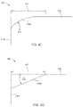
- FIG. 4C illustrates an embodiment of the arc type fillet edge
- FIG. 4D illustrates an embodiment of the straight chamfer type fillet edge
- FIGS. 4E-4G illustrate embodiments of the step type fillet edge. While FIGS. 4C-4G shown only the first fillet edge 424 a , FIGS. 4C-4G and the below measurements apply to the second fillet edge 424 b as well.
- the leading edge surface 418 a is referred to in the description of FIGS. 4C-4G , the leading edge surface 418 a is interchangeable with the trailing edge surface 418 b.
- each fillet edge 424 a , 424 b has a length 430 measured from the leading edge surface 418 a (or the trailing edge surface 418 b ) to the first surface 420 disposed as the MFS.
- the length 430 of the first and second fillet edges 424 a , 424 b may be between about 0.01 mm and about 0.50 mm.
- the fillet edge 424 a of the arc type shown in FIG. 4C may have a curvature 432 between about 0.2 mm R and about 5.0 mm R, where R describes a radius.
- curvature is an inverse relationship (i.e., 1/R)
- a larger radius refers to a less curved fillet edge and a smaller radius refers to a more curved fillet edge.
- the curvature of the section of a circle with a radius of 100 units is greater than the curvature of the section of a circle with a radius of 200 units, where curvature refers to how curved the section is.
- the fillet edge 424 a of the chamfer type shown in FIG. 4D is disposed at an angle 434 between the leading edge surface 418 a and the first surface 420 of about 0.01 degrees to about 2.0 degrees.
- the fillet edge 424 a of the step types shown in FIGS. 4E-4G may comprise one or more steps (e.g., a single step or multiple steps) produced with a lithographic mask by chemical or ion mill etching.
- a single step, or the sum of multiple steps may have a depth or height 436 recessed from the first surface 420 between about 10 nm to about 1000 nm.
- FIG. 4E illustrates a single step type fillet edge 424 a comprising a first surface 438 a substantially parallel to the leading edge surface 418 a and a second surface 438 b disposed substantially perpendicular to the first surface 438 a .
- FIG. 4F illustrates a single step type fillet edge 424 a comprising a first surface 440 a disposed substantially perpendicular to the leading edge surface 418 a and a second surface 440 b disposed at a first angle 442 from the first surface 440 a .
- the first angle 442 is between about 150 degrees to about 175 degrees, for example.
- the single step fillet edge 424 a of FIG. 4F may be formed by a chemical etching.
- FIG. 4G illustrates a multistep fillet edge 424 a comprising a first surface 444 a disposed substantially perpendicular to the leading edge surface 418 a , a second surface 444 b disposed at a first angle 446 a to the first surface 444 a , and a third surface 444 c disposed at a second angle 446 b to the second surface 444 b .
- the first angle 446 a is between about 170 degrees to about 179 degrees
- the second angle 446 b is between about 95 degrees to about 120 degrees.
- the multistep fillet edge 424 a of FIG. 4G may be formed by ion milling. While three surfaces 444 a - 444 c are shown in FIG. 4G , the multistep type may comprise a greater or fewer number of surfaces, such as four or more.
- the previously listed values and measurements of FIGS. 4C-4G are not intended to be limiting, but to provide an example of a possible embodiment.
- the first surface 422 a of the magnetic media 408 faces the slider 406 and the second surface 422 b of the magnetic media 408 disposed opposite to the first surface 422 a faces the back plate 410 .
- the second surface 422 b of the magnetic media 408 has a surface roughness greater than about 1 nm, such as about 5 nm to about 100 nm.
- conventional magnetic media have a surface roughness of less than about 0.5 nm.
- the second surface 422 b of the magnetic media 408 has a surface roughness greater than about 10 nm (e.g., greater than the surface roughness of conventional magnetic media by a magnitude).
- the first surface 420 of the back plate 410 disposed adjacent to the second surface 422 b of the magnetic media 408 has a surface roughness greater than about 1 nm, such as about 5 nm to about 100 nm.
- conventional back plates have a surface roughness of less than about 0.5 nm.
- the first surface 420 of the back plate 410 disposed adjacent to the second surface 422 b has a surface roughness greater than about 10 nm (e.g., greater than the surface roughness of conventional back plates by a magnitude).
- the first surface 422 a of the magnetic media 408 is spaced a first distance 414 a from a bottom point 426 of the slider 406 , where the bottom point 426 is the closest point of the slider 406 to the magnetic media 408 .
- the first distance 414 a is between about 5 nm and about 50 nm.
- the magnetic media 408 moves at a velocity as the magnetic media 408 travels in the magnetic media direction 416 over the back plate 410 during read and write operations.
- the velocity at which the magnetic media 408 moves may be between about 1 m/s and about 15 m/s, for example.
- an air film 412 or air pocket is formed between the first surface 420 of the back plate 410 and the second surface 422 b of the magnetic media 408 , effectively preventing the magnetic media 408 from contacting the back plate 410 .
- the magnetic media 408 is supported by the air film 412 rather than by the back plate 410 itself.
- the air film 412 forms due to a combination of factors including the velocity of the magnetic media 408 , the first and second fillet edges 424 a - 424 b , the surface roughness of the second surface 422 b of the magnetic media 408 , and the surface roughness of the first surface 420 of the back plate 410 .
- the air film 412 has a thickness such that the second surface 422 b of the magnetic media 408 is spaced a second distance 414 b from the first surface 420 of the back plate 410 .
- the term “air film” is used, it is not intend it to be limiting, and the air film can be of a different gas composition other than that of air.
- the air film 412 may comprise helium, a mixture of helium and oxygen, or a mixture including nitrogen and other gases.
- the curvature of the one or more fillet edges 424 a - 424 bd may affect the thickness (i.e., the second distance 414 b ) of the air film 412 .
- a more curved first and second fillet edge 424 a , 424 b may cause a thicker air film 412 to be formed while a less curved first and second fillet edge 424 a , 424 b may cause a thinner air film 412 to be formed.
- the second distance 414 b is between about 10 nm and about 300 nm, such that a thicker air film 412 may be closer to the upper bound of about 300 nm and a thinner air film 412 may be closer to the lower bound of about 10 nm.
- the air film 412 provides support to the magnetic media 408 , enabling the magnetic media to be stable and firm during the read and write operations of the magnetic recording head assembly 400 .
- utilizing the air film 412 to support the magnetic media 408 enables the magnetic spacing to be reduced, resulting in a higher recording density, without using a smoother magnetic media or a thinner head overcoat.
- FIG. 4B illustrates a back plate 460 that includes one or more right angle edges 462 a - 462 d (i.e., squared edges), according to some embodiments.
- a first right angle edge 462 a is disposed at a leading surface edge of the back plate 460 and the MFS and a second right angle edge 464 b is disposed at a trailing surface edge of the back plate 460 and the MFS.
- the first surface 470 of the back plate 460 disposed at the MFS couples the first right angle edge 462 a to the second right angle edge 462 b
- the leading edge surface 418 a couples the first right angle edge 462 a to a third right angle edge 462 c
- a trailing edge surface 418 b couples the second right angle edge 462 b to a fourth right angle edge 462 d
- the one or more right angle edges 462 a - 462 d may be considered skiving edges.
- the one or more right angle edges 462 a - 462 d are defined by two surfaces of the back plate 460 meeting at approximately 90 degree angles. In some embodiments, the two surfaces defining the one or more right angle edges 462 a - 462 d may be disposed at angles less than or greater than 90 degrees (e.g., 80 degrees to 100 degrees).
- the second surface 422 b of the magnetic media 408 facing the back plate 460 has a surface roughness greater than about 1 nm, such as about 5 nm to about 100 nm.
- conventional magnetic media have a surface roughness of less than about 0.5 nm.
- the second surface 422 b of the magnetic media 408 has a surface roughness greater than about 10 nm (e.g. greater than the surface roughness of conventional magnetic media by a magnitude).
- the first surface 470 of the back plate 460 disposed adjacent to the second surface 422 b of the magnetic media 408 has a surface roughness greater than about 1 nm, such as about 5 nm to about 100 nm.
- conventional back plates have a surface roughness of less than about 0.5 nm.
- the first surface 470 of the back plate 460 disposed adjacent to the second surface 422 b has a surface roughness greater than about 10 nm (e.g. greater than the surface roughness of conventional back plates by a magnitude).
- the first surface 422 a of the magnetic media 408 is spaced a first distance 454 from a bottom point 426 of the slider 406 , where the bottom point 426 is the closest point of the slider 406 to the magnetic media 408 .
- the first distance 454 is between about 3 nm and about 25 nm. Due to negative pressure, the second surface 422 b of the magnetic media 408 is in contact with the first surface 470 of the back plate 460 (i.e., spaced a distance of 0 nm), effectively eliminating any air pockets or air films. Negative pressure results when the absolute air bearing pressure is still above zero pressure but is below the external ambient pressure.
- the net pressure which is the difference between the absolute air bearing pressure and the external ambient pressure, is then negative.
- air bearing is used, it is not intend it to be limiting, and the air referred to may be a different gas composition other than that of air.
- the air referred to may be helium, a mixture of helium and oxygen, or a mixture including nitrogen and other gases.
- the back plate 460 provides support to the magnetic media 408 such that the magnetic media 408 is stable and firm during the read and write operations of the magnetic recording head assembly 450 . Because the magnetic media 408 and the first surface 470 of the back plate 460 are in contact with each other, the magnetic media 408 experiences friction from the magnetic media 408 rubbing against the back plate 460 . However, the surface roughness of the second surface 422 b of the magnetic media 408 and the surface roughness of the first surface 470 of the back plate 460 prevent stiction. Thus, the back plate 460 contacting and directly supporting the magnetic media 408 enables the magnetic spacing to be reduced, resulting in a higher recording density, without using a smoother magnetic media or a thinner head overcoat.
- FIGS. 5A and 5B illustrates of perspective views of back plates 500 , 550 , respectively, in accordance with some embodiments. Aspects of FIGS. 5A and 5B may be similar to the aspects described in FIGS. 4A and 4B , respectively.
- a first fillet edge 524 a is disposed between a leading edge surface 504 and a first surface 502 disposed at the MFS
- a second fillet edge 524 b is disposed between a trailing edge surface 506 (not shown) and the first surface 502 .
- the first and the second fillet edges 524 a , 524 b may be the first and second fillet edges 424 a , 424 b of FIG. 4 A.
- the first and second fillet edges 424 a , 424 b may be the arc type, chamfer type, or step type described in FIGS. 4C-4G .
- the first and the second fillet edges 524 a , 524 b may each have a length from the leading edge surface 504 and the trailing edge surface 506 , respectively, to the first surface 502 between about 0.01 mm to about 0.50 mm.
- the first and the second fillet edges 524 a , 524 b may each have a curvature of between about 0.2 mm R and about 5.0 mm R where R describes a radius, an angle between about 0.01 degrees and 2.0 degrees, or a step have a depth or height between about 10 nm to about 1000 nm.
- an air film or air pocket is disposed between the magnetic media and the back plate 500 such that the magnetic media does not directly contact the first and second fillet edges 524 a , 524 b or the first surface 502 .
- a first right angle edge 562 a is disposed between a leading surface 554 and a first surface 552 disposed at the MFS
- a second right angle edge 562 b is disposed between a trailing surface 556 (not shown) and the first surface 552
- the leading surface 554 and the first surface 552 meet at a substantially 90 degree angle to form the first right angle edge 562 a
- the trailing surface 556 and the first surface 552 meet at a substantially 90 degree angle to form the second right angle edge 562 b
- the first and the second right angle edges 562 a , 562 b may be the first and second right angle edges 462 a , 462 b of FIG.
- the first and second right angle edges 562 a , 562 b may be considered skiving edges.
- the magnetic media such as the magnetic media 408
- the magnetic media moves in the magnetic media direction 508 over the first surface 552 of the back plate 550
- the magnetic media contacts the first and second right angle edges 562 a , 562 b and the first surface 552 .
- the flexible magnetic media may be supported and kept firm.
- a supporting element such as a back plate or an air film induced by the back plate and the velocity of the magnetic media
- the flexible magnetic media may be supported and kept firm.
- read and write operations of a magnetic read head can successfully occur without physically contacting the magnetic media.
- supporting the magnetic media using a back plate or an air film reduces the magnetic spacing, resulting in a higher recording density. Since a smoother magnetic media or a thinner head overcoat are not utilized to lower the magnetic spacing, the magnetic recording head is more reliable than conventional magnetic recording heads.
- a data storage device comprises a magnetic recording head assembly configured to read from and write to a magnetic media, the assembly comprising a slider comprising one or more read elements and one or more write elements.
- the data storage device further comprises a back plate disposed adjacent to the slider, the back plate comprising a first surface having a roughness between about 5 nm and about 100 nm disposed at a media facing surface and one or more fillet edges disposed adjacent to the first surface.
- the magnetic media is disposed between the slider and the back plate.
- the one or more fillet edges are two fillet edges disposed adjacent to the first surface of the back plate. Each of the fillet edges is an arc, a straight chamfer, or stepped.
- a first fillet edge of the one or more fillet edges is disposed at a leading edge surface of the back plate.
- the first fillet edge has length from the leading edge surface of the back plate to the first surface of the back plate between about 0.01 mm and about 0.50 mm.
- the first fillet edge has a curvature between about 0.2 mm R to about 5.0 mm R.
- the first fillet edge is recessed a depth of about 10 nm to about 1000 nm from the first surface.
- the first fillet edge is disposed at an angle between the first surface and the leading edge surface of about 0.01 degrees to 2.0 degrees.
- a data storage device comprises magnetic recording head assembly configured to read from and write to a magnetic media, the assembly comprising a load, a suspension coupled to the load, and a slider coupled to the suspension.
- the slider comprises one or more read elements and one or more write elements.
- the data storage device further comprises a back plate having one or more fillet edges disposed adjacent to the slider.
- the magnetic media is disposed between the slider and the back plate, the magnetic media comprising a first surface spaced a first distance from the slider and a second surface spaced a second distance from the back plate.
- the one or more fillet edges cause an air film to be disposed between the second surface of the magnetic media and the back plate, the air film supporting the magnetic media.
- the thickness of the air film and the second distance are dependent on at least one of the one or more fillet edges of the back plate and a velocity of the magnetic media.
- a first fillet edge of the one or more fillet edges is disposed between the first surface and a leading edge surface of the back plate. The first fillet edge has length from the leading edge surface to the first surface between about 0.01 mm and about 0.50 mm.
- a second fillet edge of the one or more fillet edges is disposed between a trailing edge surface and the media facing surface of the back plate, the second fillet edge having a length from the trailing edge surface to the media facing surface of about 0.01 mm to about 0.50 mm.
- the first and second fillet edges each have a curvature between about 0.2 mm R to about 5.0 mm R, an angle between the media facing surface to a surface of the first fillet edge of about 0.01 degrees to 2.0 degrees, or a recessed depth from the media facing surface of the back plate of about 10 nm to about 1000 nm.
- the first distance is between about 5 nm and about 50 nm and the second distance is between about 10 nm and about 300 nm.
- the data storage device comprises a magnetic recording head assembly configured to read from and write to a magnetic media, the assembly comprising a load, a suspension coupled to the load, and a slider coupled to the suspension.
- the slider comprises one or more read elements and one or more write elements.
- the data storage device further comprises a back plate having one or more right angle edges disposed adjacent to the slider.
- the magnetic media is disposed between the slider and the back plate.
- the magnetic media includes a first surface spaced a first distance from the slider and a second surface contacting the back plate.
- the back plate has a first roughness and the second surface of the magnetic media has a second roughness.
- the first roughness is about 5 nm and about 100 nm and the second roughness is between about 5 nm and about 100 nm.
- the magnetic media contacts the back plate at a first intersection of a leading edge and a media facing surface of the back plate and a second intersection of a trailing edge and a media facing surface of the back plate.
- a first right angle edge of the one or more right angle edges is disposed at the first intersection and a second right angle edge of the one or more right angle edges is disposed at the second intersection.
- the media facing surface intersects the leading edge at an angle between about 80 degrees to about 100 degrees.
- the media facing surface intersects the trailing edge at an angle between about 80 degrees to about 100 degrees.
Abstract
Description
Claims (15)
Priority Applications (1)
| Application Number | Priority Date | Filing Date | Title |
|---|---|---|---|
| US17/184,549 US11495254B2 (en) | 2020-10-08 | 2021-02-24 | Media non-contacting magnetic recording head |
Applications Claiming Priority (2)
| Application Number | Priority Date | Filing Date | Title |
|---|---|---|---|
| US202063089430P | 2020-10-08 | 2020-10-08 | |
| US17/184,549 US11495254B2 (en) | 2020-10-08 | 2021-02-24 | Media non-contacting magnetic recording head |
Publications (2)
| Publication Number | Publication Date |
|---|---|
| US20220115037A1 US20220115037A1 (en) | 2022-04-14 |
| US11495254B2 true US11495254B2 (en) | 2022-11-08 |
Family
ID=81078175
Family Applications (1)
| Application Number | Title | Priority Date | Filing Date |
|---|---|---|---|
| US17/184,549 Active US11495254B2 (en) | 2020-10-08 | 2021-02-24 | Media non-contacting magnetic recording head |
Country Status (1)
| Country | Link |
|---|---|
| US (1) | US11495254B2 (en) |
Families Citing this family (2)
| Publication number | Priority date | Publication date | Assignee | Title |
|---|---|---|---|---|
| US20230087767A1 (en) * | 2020-08-21 | 2023-03-23 | Western Digital Technologies, Inc. | Reduction Of High Tape Contact Pressure Points Against Head Assembly |
| US11495254B2 (en) * | 2020-10-08 | 2022-11-08 | Western Digital Technologies, Inc. | Media non-contacting magnetic recording head |
Citations (28)
| Publication number | Priority date | Publication date | Assignee | Title |
|---|---|---|---|---|
| US4170033A (en) * | 1977-03-15 | 1979-10-02 | Data Recording Instrument Company Limited | Multi-track head with shielding elements interconnected with low resistance conductive paths |
| US5555043A (en) * | 1994-11-30 | 1996-09-10 | Eastman Kodak Company | Magnetics-on-film image area recording head and suspension system |
| US5870924A (en) | 1996-06-14 | 1999-02-16 | Imation Corp. | Tape bearing surface with reduced tape contact and method of making same |
| US5883770A (en) * | 1997-07-18 | 1999-03-16 | International Business Machines Corporation | Partial width mass produced linear tape recording head |
| US5976668A (en) * | 1995-02-28 | 1999-11-02 | Sony Corporation | Base film for magnetic recording medium and magnetic recording medium using same |
| US5982592A (en) * | 1995-11-20 | 1999-11-09 | Sony Corporation | Magnetic tape stabilizer for a recording and playback device |
| US6118626A (en) * | 1997-03-11 | 2000-09-12 | Massachusetts Institute Of Technology | Contact sheet recording with a self-acting negative air bearing |
| US7054101B1 (en) * | 2002-10-23 | 2006-05-30 | Moutain Engineering Ii, Inc. | System for high density linear serpentine data recording |
| US20060232884A1 (en) | 2003-12-17 | 2006-10-19 | Biskeborn Robert G | Tape head having a support plate with contoured surface |
| US20080170328A1 (en) * | 2007-01-12 | 2008-07-17 | Shinji Kawakami | Magnetic head |
| US20090052087A1 (en) * | 2007-08-23 | 2009-02-26 | David Berman | Air bearing at opposite side of linear tape to support tape into contact with head slider |
| US20090231757A1 (en) * | 2008-03-12 | 2009-09-17 | Robert Glenn Biskeborn | Head for tape drive with transversely varying contour |
| US7646565B2 (en) * | 2006-08-08 | 2010-01-12 | International Business Machines Corporation | Tape head with outrigger |
| US7660072B2 (en) * | 2005-08-26 | 2010-02-09 | International Business Machines Corporation | Magnetic head with planar outrigger |
| US20120008234A1 (en) * | 2010-07-06 | 2012-01-12 | International Business Machines Corporation | Low friction tape head and system implementing same |
| US20120183907A1 (en) | 2011-01-19 | 2012-07-19 | International Business Machines Corporation | Patterning process for small devices |
| US8243396B2 (en) * | 2007-09-07 | 2012-08-14 | International Business Machines Corporation | Tape drive system |
| WO2014149055A1 (en) * | 2013-03-22 | 2014-09-25 | Hewlett-Packard Development Company, L.P. | Reduced contact read/write head |
| GB2515051A (en) * | 2013-06-12 | 2014-12-17 | Ibm | Tape head with tape-bearing surface exhibiting an array of protruding topographic features |
| US9087553B2 (en) | 2013-04-29 | 2015-07-21 | International Business Machines Corporation | Tape head with thermal tape-head distance sensor |
| US20160055867A1 (en) * | 2014-08-20 | 2016-02-25 | International Business Machines Corporation | Tape heads with sub-ambient pressure cavities |
| US20160284377A1 (en) * | 2015-03-27 | 2016-09-29 | Fujifilm Corporation | Reel |
| US9837104B1 (en) * | 2016-10-31 | 2017-12-05 | International Business Machines Corporation | Tape head having sensors proximate to an edge |
| US20180158472A1 (en) * | 2016-12-05 | 2018-06-07 | International Business Machines Corporation | Head having wrap-controlled flexible media interface |
| US20200258544A1 (en) * | 2019-02-08 | 2020-08-13 | Western Digital Technologies, Inc. | Tape embedded drive |
| US20200342905A1 (en) * | 2019-04-26 | 2020-10-29 | Sony Corporation | Magnetic recording medium |
| US20220115037A1 (en) * | 2020-10-08 | 2022-04-14 | Western Digital Technologies, Inc. | Media Non-Contacting Magnetic Recording Head |
| US20220148618A1 (en) * | 2019-03-29 | 2022-05-12 | Sony Group Corporation | Magnetic recording medium and cartridge |
-
2021
- 2021-02-24 US US17/184,549 patent/US11495254B2/en active Active
Patent Citations (34)
| Publication number | Priority date | Publication date | Assignee | Title |
|---|---|---|---|---|
| US4170033A (en) * | 1977-03-15 | 1979-10-02 | Data Recording Instrument Company Limited | Multi-track head with shielding elements interconnected with low resistance conductive paths |
| US5555043A (en) * | 1994-11-30 | 1996-09-10 | Eastman Kodak Company | Magnetics-on-film image area recording head and suspension system |
| US5976668A (en) * | 1995-02-28 | 1999-11-02 | Sony Corporation | Base film for magnetic recording medium and magnetic recording medium using same |
| US5982592A (en) * | 1995-11-20 | 1999-11-09 | Sony Corporation | Magnetic tape stabilizer for a recording and playback device |
| US5870924A (en) | 1996-06-14 | 1999-02-16 | Imation Corp. | Tape bearing surface with reduced tape contact and method of making same |
| US6118626A (en) * | 1997-03-11 | 2000-09-12 | Massachusetts Institute Of Technology | Contact sheet recording with a self-acting negative air bearing |
| US5883770A (en) * | 1997-07-18 | 1999-03-16 | International Business Machines Corporation | Partial width mass produced linear tape recording head |
| US7054101B1 (en) * | 2002-10-23 | 2006-05-30 | Moutain Engineering Ii, Inc. | System for high density linear serpentine data recording |
| US20060232884A1 (en) | 2003-12-17 | 2006-10-19 | Biskeborn Robert G | Tape head having a support plate with contoured surface |
| US7660072B2 (en) * | 2005-08-26 | 2010-02-09 | International Business Machines Corporation | Magnetic head with planar outrigger |
| US7646565B2 (en) * | 2006-08-08 | 2010-01-12 | International Business Machines Corporation | Tape head with outrigger |
| US20080170328A1 (en) * | 2007-01-12 | 2008-07-17 | Shinji Kawakami | Magnetic head |
| US20090052087A1 (en) * | 2007-08-23 | 2009-02-26 | David Berman | Air bearing at opposite side of linear tape to support tape into contact with head slider |
| US20090052082A1 (en) * | 2007-08-23 | 2009-02-26 | David Berman | Air bearing at opposite side of linear tape to support tape into contact with head slider |
| US7869163B2 (en) | 2007-08-23 | 2011-01-11 | International Business Machines Corporation | Air bearing at opposite side of linear tape to support tape into contact with head slider |
| US8243396B2 (en) * | 2007-09-07 | 2012-08-14 | International Business Machines Corporation | Tape drive system |
| US20090231757A1 (en) * | 2008-03-12 | 2009-09-17 | Robert Glenn Biskeborn | Head for tape drive with transversely varying contour |
| US20120008234A1 (en) * | 2010-07-06 | 2012-01-12 | International Business Machines Corporation | Low friction tape head and system implementing same |
| US20120183907A1 (en) | 2011-01-19 | 2012-07-19 | International Business Machines Corporation | Patterning process for small devices |
| WO2014149055A1 (en) * | 2013-03-22 | 2014-09-25 | Hewlett-Packard Development Company, L.P. | Reduced contact read/write head |
| US20150364154A1 (en) * | 2013-03-22 | 2015-12-17 | Hewlett-Packard Development Company, L.P. | Reduced contact read/write head |
| US9087553B2 (en) | 2013-04-29 | 2015-07-21 | International Business Machines Corporation | Tape head with thermal tape-head distance sensor |
| GB2515051A (en) * | 2013-06-12 | 2014-12-17 | Ibm | Tape head with tape-bearing surface exhibiting an array of protruding topographic features |
| US20160055867A1 (en) * | 2014-08-20 | 2016-02-25 | International Business Machines Corporation | Tape heads with sub-ambient pressure cavities |
| US9734854B2 (en) * | 2014-08-20 | 2017-08-15 | International Business Machines Corporation | Tape heads with sub-ambient pressure cavities |
| US20160284377A1 (en) * | 2015-03-27 | 2016-09-29 | Fujifilm Corporation | Reel |
| US9837104B1 (en) * | 2016-10-31 | 2017-12-05 | International Business Machines Corporation | Tape head having sensors proximate to an edge |
| US20180158472A1 (en) * | 2016-12-05 | 2018-06-07 | International Business Machines Corporation | Head having wrap-controlled flexible media interface |
| US10068591B2 (en) * | 2016-12-05 | 2018-09-04 | International Business Machines Corporation | Head having wrap-controlled flexible media interface |
| US20200258544A1 (en) * | 2019-02-08 | 2020-08-13 | Western Digital Technologies, Inc. | Tape embedded drive |
| US10991390B2 (en) * | 2019-02-08 | 2021-04-27 | Western Digital Technologies, Inc. | Head assembly with suspension system for a tape embedded drive |
| US20220148618A1 (en) * | 2019-03-29 | 2022-05-12 | Sony Group Corporation | Magnetic recording medium and cartridge |
| US20200342905A1 (en) * | 2019-04-26 | 2020-10-29 | Sony Corporation | Magnetic recording medium |
| US20220115037A1 (en) * | 2020-10-08 | 2022-04-14 | Western Digital Technologies, Inc. | Media Non-Contacting Magnetic Recording Head |
Non-Patent Citations (2)
| Title |
|---|
| Beardsley, Irene A. et al., "Improved Calibration Techniques for High Density Tape Recording Systems", IEEE Transactions on Magnetics, vol. 28, No. 6, Nov. 1992, pp. 3417-3419. |
| Manavi et al. "Optical Head Design for 1TB Optical Tape drive," 2000, 14 pages. |
Also Published As
| Publication number | Publication date |
|---|---|
| US20220115037A1 (en) | 2022-04-14 |
Similar Documents
| Publication | Publication Date | Title |
|---|---|---|
| US11393498B2 (en) | Head assembly with suspension system for a tape embedded drive | |
| US11495254B2 (en) | Media non-contacting magnetic recording head | |
| US10971184B1 (en) | Dual drive tape embedded system | |
| US11081132B1 (en) | Tape embedded drive with HDD components | |
| US10997998B1 (en) | Tape embedded drive with tied spindle structure | |
| US11495270B2 (en) | Tape embedded drive with multiple feedthrough connections | |
| US20220208224A1 (en) | Tape drive with head-gimbal assembly and contact plate | |
| US11532325B1 (en) | Two-dimensional magnetic recording (TDMR) for high areal density tape drive | |
| US10998008B1 (en) | Interface connector for tape embedded drive | |
| US11670329B1 (en) | Two-dimensional magnetic recording (TDMR) to counter tape dimensional stability (TDS) errors in a tape media | |
| US11211086B1 (en) | Embedded tape reel lock mechanism for tape embedded storage drive | |
| US11295771B2 (en) | Head positioning assembly for tape embedded drive | |
| US11532320B1 (en) | Tape drive configured to enable magnetic media to fly above an upstream or a downstream head assembly | |
| US11682419B2 (en) | Magnetic head with assisted magnetic recording | |
| US11227628B1 (en) | Recessed tape servo head to create an equipotential tape bearing surface | |
| US20220059128A1 (en) | Reduction Of High Tape Contact Pressure Points Against Head Assembly | |
| US20230087767A1 (en) | Reduction Of High Tape Contact Pressure Points Against Head Assembly | |
| US11373677B2 (en) | Double bend VCM yoke structure | |
| US11417360B1 (en) | Tape support system with a load-unload mechanism | |
| US11935563B2 (en) | Tape drive having independently controlled tilting tandem tape heads | |
| US11295769B2 (en) | Soft mount voice coil motor assembly | |
| US11776569B1 (en) | Tape recording system and method for reading media having write-append head-positioning based on change in tape lateral dimension | |
| US11189307B1 (en) | Base apparatus and methods for head assemblies of magnetic storage devices | |
| US11735223B2 (en) | Head suspension system for a tape drive |
Legal Events
| Date | Code | Title | Description |
|---|---|---|---|
| FEPP | Fee payment procedure |
Free format text: ENTITY STATUS SET TO UNDISCOUNTED (ORIGINAL EVENT CODE: BIG.); ENTITY STATUS OF PATENT OWNER: LARGE ENTITY |
|
| AS | Assignment |
Owner name: WESTERN DIGITAL TECHNOLOGIES, INC., CALIFORNIA Free format text: ASSIGNMENT OF ASSIGNORS INTEREST;ASSIGNORS:KUROKI, KENJI;RUIZ, OSCAR;REEL/FRAME:055597/0195 Effective date: 20201007 |
|
| AS | Assignment |
Owner name: JPMORGAN CHASE BANK, N.A., AS AGENT, ILLINOIS Free format text: SECURITY INTEREST;ASSIGNOR:WESTERN DIGITAL TECHNOLOGIES, INC.;REEL/FRAME:056285/0292 Effective date: 20210507 |
|
| STPP | Information on status: patent application and granting procedure in general |
Free format text: NON FINAL ACTION MAILED |
|
| AS | Assignment |
Owner name: WESTERN DIGITAL TECHNOLOGIES, INC., CALIFORNIA Free format text: RELEASE OF SECURITY INTEREST AT REEL 056285 FRAME 0292;ASSIGNOR:JPMORGAN CHASE BANK, N.A.;REEL/FRAME:058982/0001 Effective date: 20220203 |
|
| STPP | Information on status: patent application and granting procedure in general |
Free format text: RESPONSE TO NON-FINAL OFFICE ACTION ENTERED AND FORWARDED TO EXAMINER |
|
| STPP | Information on status: patent application and granting procedure in general |
Free format text: FINAL REJECTION MAILED |
|
| STPP | Information on status: patent application and granting procedure in general |
Free format text: NOTICE OF ALLOWANCE MAILED -- APPLICATION RECEIVED IN OFFICE OF PUBLICATIONS |
|
| STPP | Information on status: patent application and granting procedure in general |
Free format text: PUBLICATIONS -- ISSUE FEE PAYMENT VERIFIED |
|
| STCF | Information on status: patent grant |
Free format text: PATENTED CASE |
|
| AS | Assignment |
Owner name: JPMORGAN CHASE BANK, N.A., ILLINOIS Free format text: PATENT COLLATERAL AGREEMENT - A&R LOAN AGREEMENT;ASSIGNOR:WESTERN DIGITAL TECHNOLOGIES, INC.;REEL/FRAME:064715/0001 Effective date: 20230818 Owner name: JPMORGAN CHASE BANK, N.A., ILLINOIS Free format text: PATENT COLLATERAL AGREEMENT - DDTL LOAN AGREEMENT;ASSIGNOR:WESTERN DIGITAL TECHNOLOGIES, INC.;REEL/FRAME:067045/0156 Effective date: 20230818 |