US11489397B2 - Drive device - Google Patents
Drive device Download PDFInfo
- Publication number
- US11489397B2 US11489397B2 US16/874,637 US202016874637A US11489397B2 US 11489397 B2 US11489397 B2 US 11489397B2 US 202016874637 A US202016874637 A US 202016874637A US 11489397 B2 US11489397 B2 US 11489397B2
- Authority
- US
- United States
- Prior art keywords
- outer peripheral
- adhesion
- recess portion
- facing surface
- drive device
- Prior art date
- Legal status (The legal status is an assumption and is not a legal conclusion. Google has not performed a legal analysis and makes no representation as to the accuracy of the status listed.)
- Active, expires
Links
Images


Classifications
-
- H—ELECTRICITY
- H02—GENERATION; CONVERSION OR DISTRIBUTION OF ELECTRIC POWER
- H02K—DYNAMO-ELECTRIC MACHINES
- H02K11/00—Structural association of dynamo-electric machines with electric components or with devices for shielding, monitoring or protection
- H02K11/30—Structural association with control circuits or drive circuits
- H02K11/33—Drive circuits, e.g. power electronics
-
- B—PERFORMING OPERATIONS; TRANSPORTING
- B62—LAND VEHICLES FOR TRAVELLING OTHERWISE THAN ON RAILS
- B62D—MOTOR VEHICLES; TRAILERS
- B62D5/00—Power-assisted or power-driven steering
- B62D5/04—Power-assisted or power-driven steering electrical, e.g. using an electric servo-motor connected to, or forming part of, the steering gear
- B62D5/0403—Power-assisted or power-driven steering electrical, e.g. using an electric servo-motor connected to, or forming part of, the steering gear characterised by constructional features, e.g. common housing for motor and gear box
-
- B—PERFORMING OPERATIONS; TRANSPORTING
- B62—LAND VEHICLES FOR TRAVELLING OTHERWISE THAN ON RAILS
- B62D—MOTOR VEHICLES; TRAILERS
- B62D5/00—Power-assisted or power-driven steering
- B62D5/04—Power-assisted or power-driven steering electrical, e.g. using an electric servo-motor connected to, or forming part of, the steering gear
- B62D5/0457—Power-assisted or power-driven steering electrical, e.g. using an electric servo-motor connected to, or forming part of, the steering gear characterised by control features of the drive means as such
- B62D5/046—Controlling the motor
-
- H—ELECTRICITY
- H02—GENERATION; CONVERSION OR DISTRIBUTION OF ELECTRIC POWER
- H02K—DYNAMO-ELECTRIC MACHINES
- H02K5/00—Casings; Enclosures; Supports
- H02K5/04—Casings or enclosures characterised by the shape, form or construction thereof
-
- H—ELECTRICITY
- H02—GENERATION; CONVERSION OR DISTRIBUTION OF ELECTRIC POWER
- H02K—DYNAMO-ELECTRIC MACHINES
- H02K5/00—Casings; Enclosures; Supports
- H02K5/04—Casings or enclosures characterised by the shape, form or construction thereof
- H02K5/10—Casings or enclosures characterised by the shape, form or construction thereof with arrangements for protection from ingress, e.g. water or fingers
-
- H—ELECTRICITY
- H02—GENERATION; CONVERSION OR DISTRIBUTION OF ELECTRIC POWER
- H02K—DYNAMO-ELECTRIC MACHINES
- H02K5/00—Casings; Enclosures; Supports
- H02K5/04—Casings or enclosures characterised by the shape, form or construction thereof
- H02K5/22—Auxiliary parts of casings not covered by groups H02K5/06-H02K5/20, e.g. shaped to form connection boxes or terminal boxes
- H02K5/225—Terminal boxes or connection arrangements
Definitions
- the disclosure in this specification relates to a drive device.
- a drive device typically includes several components that are assembled together, such as a motor, a housing, and a cover.
- a drive device in one aspect of this disclosure, includes a drive unit having an annular shaped adhesion recess portion, a cover including an annular shaped adhesion protrusion portion that faces the adhesion recess portion, an adhesive sealant that adheres the adhesion recess portion to the adhesion protrusion portion, and a spacer that maintains a distance between the adhesion recess portion and the adhesion protrusion portion.
- FIG. 1 is a top view showing a drive device.
- FIG. 2 is a cross-sectional view showing a cross section taken along line II-II of FIG. 1 .
- FIG. 3 is a perspective view showing a drive unit.
- FIG. 4 is a perspective view showing an annular cover.
- FIG. 5 is a partial enlarged view showing an adhesion portion between a drive unit and an annular cover.
- FIG. 6 is an explanatory diagram showing a state before bonding between an outer peripheral adhesion protrusion portion and an outer peripheral adhesion recess portion.
- FIG. 7 is an explanatory view showing a state after bonding between an outer peripheral adhesion protrusion portion and an outer peripheral adhesion recess portion.
- FIG. 8 is an explanatory diagram showing a state before bonding between an outer peripheral adhesion protrusion portion and an outer peripheral adhesion recess portion in a second embodiment.
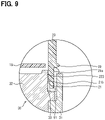
- FIG. 9 is an explanatory diagram showing a state after bonding between an outer peripheral adhesion protrusion portion and an outer peripheral adhesion recess portion in a second embodiment.
- a drive device 1 is a device that performs electric drive operation, and can be used as a rotating electric machine device such as a motor device or a power generation device. Alternatively, the drive device 1 can also be used for an actuator device that does not involve rotation.
- the drive device 1 can be used, for example, as a device mounted on a vehicle and constituting a part of an electric power steering device.
- a case where the drive device 1 is used as a part of an electric power steering device for a vehicle will be described as an example.
- the drive device 1 includes a drive unit 10 and an annular cover 20 .
- the drive unit 10 includes a motor 11 , a circuit substrate 15 , a frame 30 , and a connector 41 .
- the motor 11 is an electric motor that converts electric energy into rotational motion.
- the motor 11 is a device that provides the driving force of the drive device 1 . Alternatively, this driving force may be provided by using a device such as an actuator instead of the motor 11 .
- the frame 30 has a bottomed cylindrical shape.
- the frame 30 includes a motor case 31 that is a cylindrical body, and a frame end 32 that forms a bottom surface.
- the term “bottom” refers to the closed portion of the frame 30 , and is not intended to refer to directionality.
- the frame 30 houses the motor 11 in a housing space surrounded by the motor case 31 and the frame end 32 .
- the motor case 31 and the frame end 32 are made of a metal material having high thermal conductivity.
- the circuit substrate 15 includes a plurality of circuit components for controlling the motor 11 . Part of the circuit substrate 15 is in contact with the frame end 32 . Heat generated in the circuit components of the circuit substrate 15 is transmitted to the frame end 32 and dissipated from the frame end 32 . In other words, the frame end 32 functions as a heat sink that promotes cooling of the circuit substrate 15 .
- the connector 41 is a component for transmitting signals, electric power, etc. from outside the drive device 1 to the motor 11 and the circuit substrate 15 .
- the annular cover 20 is mounted on the drive unit 10 .
- the annular cover 20 is smaller than the drive unit 10 .
- the annular cover 20 is lighter than the drive unit 10 .
- the annular cover 20 has an inner peripheral opening 29 forming an opening at the center of the annular cover 20 .
- the annular cover 20 is a resin component and may be formed of, for example, a resin such as polybutylene terephthalate.
- the annular cover 20 is one example of a cover.
- the circuit substrate 15 has a disk shape.
- the circuit substrate 15 is provided so as to cover the frame end 32 .
- An outer peripheral adhesion recess portion 35 is formed in the frame 30 .
- the outer peripheral adhesion recess portion 35 has a continuous annular shape.
- the outer peripheral adhesion recess portion 35 is provided radially outward of the circuit substrate 15 .
- radially refers to the rotation axis of the motor 11 .
- the outer peripheral adhesion recess portion 35 is formed by two members, the motor case 31 and the frame end 32 .
- the connector 41 has an inner peripheral adhesion recess portion 45 formed therein.
- the inner peripheral adhesion recess portion 45 has a continuous annular shape.
- the inner peripheral adhesion recess portion 45 is provided radially inward of the outer peripheral adhesion recess portion 35 with respect to the rotation axis of the motor 11 .
- the inner peripheral adhesion recess portion 45 is provided at a position away from the frame end 32 . In other words, the inner peripheral adhesion recess portion 45 is provided at a position shifted from the outer peripheral adhesion recess portion 35 along the axial direction of the rotation axis of the motor 11 .
- the annular cover 20 has a bottomed cylindrical shape. At the center of the bottom surface of the annular cover 20 , an inner peripheral opening 29 forming a substantially circular opening is provided.
- the term “bottom” is only intended to refer to the closed side of the annular cover 20 , and does not limit directionality.
- the shape of the inner peripheral opening 29 may be any shape as long as at least a part of the connector 41 can be exposed to the outside, and is not limited to a substantially circular shape.
- the shape may be a square shape or a semicircle shape, or may be a complex shape formed by combining various shapes.
- the annular cover 20 includes the inner peripheral opening 29 which is an inner peripheral end portion, and also includes an outer peripheral end portion which is on the opposite side as the inner peripheral end portion.
- the outer peripheral end portion is located outward of the inner peripheral end portion.
- An outer peripheral adhesion protrusion portion 21 is formed on the outer peripheral end portion.
- the outer peripheral adhesion protrusion portion 21 protrudes toward the frame 30 .
- the outer peripheral adhesion protrusion portion 21 is provided continuously in an annular shape over the entire outer peripheral end portion.
- An outer surface protrusion portion 22 that protrudes from the outer surface of the annular cover 20 is formed near the outer peripheral adhesion protrusion portion 21 .
- the protruding direction of the outer peripheral adhesion protrusion portion 21 and the protruding direction of the outer surface protrusion portion 22 are directions which intersect each other.
- the outer surface protrusion portion 22 is provided continuously in an annular shape along the outer surface of the annular cover 20 .
- the outer surface protrusion portion 22 faces the motor case 31 .
- a spacer 23 is provided on the outer surface of the outer peripheral adhesion protrusion portion 21 .
- the spacer 23 is a ridge provided so as to protrude along a direction along the axial direction of the cylindrical annular cover 20 .
- the spacer 23 is provided from the outer surface protrusion portion 22 to the outer peripheral adhesion protrusion portion 21 .
- a plurality of spacers 23 are provided on the outer surface of the outer peripheral adhesion protrusion portion 21 .
- the plurality of spacers 23 are provided at eight locations and lined up so as to form a discontinuous annular shape. Adjacent spacers 23 are arranged at equal intervals. It should be noted that the number of spacers 23 is not limited to eight, and may be more or less than eight. For example, spacers 23 may be provided at three locations so as to form a triangle with each other.
- the spacer 23 has a semicircular cross section. Thereby, even when the spacer 23 comes into contact with another component, it is easy to avoid the spacer 23 being significantly crushed. For this reason, the amount that the outer peripheral adhesion protrusion portion 21 protrudes from the outer surface is reliably maintained, and the spacer 23 reliably functions as a spacer to retain spacing.
- the cross-sectional shape of the spacer 23 is not limited to a semicircle.
- the shape may be triangular or square.
- the spacer 23 forms a gap between the outer peripheral adhesion protrusion portion 21 and the outer peripheral adhesion recess portion 35 .
- the size of this gap is equal to the amount of protrusion of the spacer 23 from the outer surface of the outer peripheral adhesion protrusion portion 21 .
- the gap between the outer peripheral adhesion protrusion portion 21 and the outer peripheral adhesion recess portion 35 can be increased by increasing the protrusion amount of the spacer 23 .
- An inner peripheral adhesion protrusion portion 26 is formed on the inner peripheral end portion, i.e., the inner peripheral opening 29 .
- the inner peripheral adhesion protrusion portion 26 protrudes toward facing the frame 30 .
- the inner peripheral adhesion protrusion portion 26 protrudes in a direction along the axial direction of the annular cover 20 and has a cylindrical shape.
- the inner peripheral adhesion protrusion portion 26 is provided continuously in an annular over the entire inner peripheral end portion.
- the outer peripheral adhesion protrusion portion 21 and the outer peripheral adhesion recess portion 35 are bonded and fixed by an outer peripheral adhesive 91 provided continuously in a ring shape. This prevents the relative position between the annular cover 20 and the connector 41 from changing. In other words, the outer peripheral adhesive 91 prevents the annular cover 20 from slipping out of the drive unit 10 . The outer peripheral adhesive 91 prevents water and dust from entering any gaps between the outer peripheral adhesion protrusion portion 21 and the outer peripheral adhesion recess portion 35 .
- the outer peripheral adhesive 91 has two functions: a function of bonding and fixing the connector 41 to the annular cover 20 , and a function of preventing foreign matter from entering between the connector 41 and the annular cover 20 .
- the outer peripheral adhesive 91 is an example of an adhesive sealant.
- the inner peripheral adhesion protrusion portion 26 and the inner peripheral adhesion recess portion 45 are adhered and fixed to each other by an inner peripheral adhesive 92 continuously provided in a ring shape. This prevents the relative position between the annular cover 20 and the frame 30 from changing. In other words, the inner peripheral adhesive 92 prevents the annular cover 20 from slipping out of the drive unit 10 . The inner peripheral adhesive 92 prevents water and dust from entering through any gaps between the inner peripheral adhesion protrusion portion 26 and the inner peripheral adhesion recess portion 45 . In summary, the inner peripheral adhesive 92 has two functions: a function of bonding and fixing the frame 30 to the annular cover 20 , and a sealing function of preventing foreign matter from entering between the frame 30 and the annular cover 20 .
- the outer peripheral adhesive 91 and the inner peripheral adhesive 92 for example, a silicone-based adhesive can be used.
- the outer peripheral adhesive 91 and the inner peripheral adhesive 92 only need to have a function of bonding components and a sealing function of preventing foreign matter such as water from entering from a portion where the components are bonded.
- the present disclosure is not limited to using silicone-based adhesives.
- an acrylic adhesive or an epoxy adhesive can be used.
- FIG. 6 shows a state before the outer peripheral adhesion protrusion portion 21 and the outer peripheral adhesion recess portion 35 are bonded and fixed to each other.
- the outer peripheral adhesive 91 is provided in the outer peripheral adhesion recess portion 35 surrounded on three sides.
- the outer peripheral adhesive 91 is applied so as to be in contact with two components, i.e., the motor case 31 and the frame end 32 . At this point, the outer peripheral adhesive 91 is in a soft state prior to hardening.
- the annular cover 20 is moved closer to the frame 30 to which the outer peripheral adhesive 91 has been applied, and the outer peripheral adhesion protrusion portion 21 is inserted into the outer peripheral adhesion recess portion 35 .
- the direction in which the outer peripheral adhesion protrusion portion 21 is inserted into the outer peripheral adhesion recess portion 35 is the direction in which the annular cover 20 is mounted.
- the annular cover 20 is moved in the mounting direction beyond the position where the outer peripheral adhesion protrusion portion 21 contacts the outer peripheral adhesive 91 .
- the outer peripheral adhesive 91 is pushed out by the outer peripheral adhesion protrusion portion 21 , and the outer peripheral adhesive 91 spreads to each corner. Therefore, even if the outer peripheral adhesive 91 is discontinuously applied prior to the bonding, the outer peripheral adhesive 91 is expanded and spread by the outer peripheral adhesion protrusion portion 21 so that the outer peripheral adhesive 91 is continuously provided in a ring shape.
- FIG. 7 shows a state after the outer peripheral adhesion protrusion portion 21 and the outer peripheral adhesion recess portion 35 are adhesively to each other.
- the outer peripheral adhesive 91 is in contact with three components in this state, i.e., the motor case 31 , the frame end 32 , and the annular cover 20 .
- the outer peripheral adhesive 91 is solidified in a state of being disposed continuously in a ring shape. Therefore, the outer peripheral adhesive 91 adhesively fixes the three components to each other, i.e., the motor case 31 , the frame end 32 , and the annular cover 20 .
- the outer peripheral adhesive 91 prevents foreign substances from entering between the motor case 31 and the annular cover 20 and also prevents foreign substances from entering between the frame end 32 and the annular cover 20 .
- the outer peripheral adhesion protrusion portion 21 has a plurality of opposing surfaces facing the outer peripheral adhesion recess portion 35 .
- the surfaces facing directions intersecting the mounting direction of the annular cover 20 are side opposing surfaces.
- the side facing surfaces of the outer peripheral adhesion protrusion portion 21 include an outward facing surface 21 a and an inward facing surface 21 b .
- the outward facing surface 21 a faces the outer side surface of the outer peripheral adhesion recess portion 35 located radially outward with respect to the rotation axis of the motor 11 .
- the inward facing surface 21 b is faces the inner side surface of the outer peripheral adhesion recess portion 35 located radially inward with respect to the rotation axis of the motor 11 .
- the spacer 23 is provided only on the outward facing surface 21 a , and is not provided on the inward facing surface 21 b .
- the spacer 23 is in contact with the outer peripheral adhesion recess portion 35 . Therefore, there is a space between the portions of the outward facing surface 21 a where the spacer 23 is not provided and the outer peripheral adhesion recess portion 35 .
- the size of this space is equal to the protrusion amount of the spacer 23 .
- the outer peripheral adhesive 91 penetrates into this space to adhere and fix the outward facing surface 21 a to the outer peripheral adhesion recess portion 35 .
- the spacer 23 is not necessarily in contact with the outer peripheral adhesion recess portion 35 .
- a space facing the outer peripheral adhesion recess portion 35 may be appropriately formed to allow the outer peripheral adhesive 91 to enter.
- the outer peripheral adhesive 91 Prior to hardening, the outer peripheral adhesive 91 spreads to fill the space between the outward facing surface 21 a and the outer peripheral adhesion recess portion 35 formed by the spacer 23 , and reaches the outer surface protrusion portion 22 . Upon reaching the outer surface protrusion portion 22 , the outer peripheral adhesive 91 is unable to further spread along the outer surface of the annular cover 20 in the mounting direction. For this reason, the outer peripheral adhesive 91 then spreads in a direction intersecting the mounting direction, with the movement direction being restricted by the outer surface protrusion portion 22 . At this time, a part of the outer peripheral adhesive 91 reaches a space between the outer surface protrusion portion 22 and the motor case 31 .
- a part of the outer peripheral adhesive 91 adheres the outer surface protrusion portion 22 to the end of the motor case 31 . Therefore, compared to the case where the outer surface protrusion portion 22 is not provided, a larger bonding surface can be ensured.
- the outer peripheral adhesive 91 it is preferable to use an opaque adhesive as the outer peripheral adhesive 91 so the presence of the outer peripheral adhesive 91 can be more easily confirmed visually.
- the color of the outer peripheral adhesive 91 is preferably different from the color of the annular cover 20 and the motor case 31 .
- the outer surface protrusion portion 22 which protrudes as an eave from the outer surface of the annular cover 20 , also functions to protect the outer peripheral adhesive 91 from external impacts. For example, even if pebbles or the like are likely to collide with the outer peripheral adhesive 91 exposed on the outer surface of the drive device 1 , the pebbles are less likely to directly collide with the outer peripheral adhesive 91 due to collision with the outer surface protrusion portion 22 . According to this, it is possible to prevent the outer peripheral adhesive 91 from peeling off the annular cover 20 and the frame 30 due to external impacts, and prevent the outer peripheral adhesive 91 from being cracked.
- the outer peripheral adhesive 91 can easily perform the two functions bonding and fixing the components to each other as well as preventing foreign substances from entering the drive device 1 over a long period of time.
- the drive device 1 is mounted on a vehicle, the drive device 1 is likely to come into contact with pebbles or the like during traveling. Therefore, a configuration for protecting the outer peripheral adhesive 91 from collision with pebbles or the like is very useful when the drive device 1 is used for a vehicle.
- the thickness of the outer peripheral adhesive 91 located between the inward facing surface 21 b and the outer peripheral adhesion recess portion 35 is larger than the thickness of the outer peripheral adhesive 91 located between the outward facing surface 21 a and the outer peripheral adhesion recess portion 35 .
- the distance between the inward facing surface 21 b and the outer peripheral adhesion recess portion 35 is greater than the amount of protrusion of the spacer 23 . Accordingly, it is easier to maintain a state in which the outer peripheral adhesive 91 is continuously provided in a ring shape on the side opposite to the side on which the spacers 23 are provided. Therefore, the outer peripheral adhesive 91 can more reliably prevent foreign matter from entering between the frame end 32 and the annular cover 20 .
- the drive device 1 includes the spacers 23 that maintain a distance between the outer peripheral adhesion recess portion 35 and the outer peripheral adhesion protrusion portion 21 . Therefore, a space is formed between the outer peripheral adhesion recess portion 35 and the outer peripheral adhesion protrusion portion 21 into which the outer peripheral adhesive 91 can enter. As a result, it is easier to ensure a large bonding area between the outer peripheral adhesion recess portion 35 and the outer peripheral adhesion protrusion portion 21 that is bonded by the outer peripheral adhesive 91 .
- the spacers 23 are provided so as to protrude from the side facing surface of the outer peripheral adhesion protrusion portion 21 facing the outer peripheral adhesion recess portion 35 .
- the spacers 23 protrude toward the outer peripheral adhesion recess portion 35 .
- the spacers 23 can be directly disposed at portions where a space for the outer peripheral adhesive 91 should be formed. Therefore, it is possible to ensure a large bonding surface for the outer peripheral adhesive 91 with a simple configuration by using the spacers 23 .
- the adhesion between the drive unit 10 and the annular cover 20 can be stabilized with a simple configuration as compared with a case where a space is secured by disposing another component.
- Adjacent spacers 23 are provided at positions separated from each other at equal intervals. For this reason, it is easier to avoid a portion where the outer peripheral adhesion recess portion 35 and the outer peripheral adhesion protrusion portion 21 are not bonded by the outer peripheral adhesive 91 being biased to a specific portion. Therefore, it is easier to control the outer peripheral adhesive 91 to a desired thickness, for example, by making the thickness of the outer peripheral adhesive 91 uniform.
- the outer peripheral adhesive 91 is provided in an annular shape continuously between the outer surface of the outer peripheral adhesion protrusion portion 21 and the outer peripheral adhesion recess portion 35 where the spacers 23 are not provided. For this reason, intrusion of foreign matter into the inside can be prevented to a greater degree than at least the outer peripheral adhesive 91 being provided continuously in a ring shape.
- the outer peripheral adhesive 91 positioned between the outer peripheral adhesion recess portion 35 and the side of the outer peripheral adhesion protrusion portion 21 where the spacer 23 is provided may be discontinuous. Therefore, by making at least a part of the outer peripheral adhesion protrusion portion 21 continuous in an annular shape, the outer peripheral adhesive 91 can exhibit a sealing function of preventing foreign matter from entering the drive device 1 .
- the outer peripheral adhesion recess portion 35 is formed in the frame 30 .
- the annular cover 20 can be directly adhered and fixed to the frame 30 which is a component for fixing the motor 11 . Therefore, compared to the case where the annular cover 20 is indirectly fixed to the frame 30 , the state in which the frame 30 and the annular cover 20 are adhesively fixed to each other is more easily maintained. If the annular cover 20 is fixed to the connector 41 , the annular cover 20 will be detached from the drive unit 10 not only when the annular cover 20 is detached from the connector 41 but also when the connector 41 is detached from the frame 30 . In particular, when the drive device 1 is mounted on a vehicle, the drive device 1 is easily affected by vibrations during traveling. For this reason, the configuration in which the annular cover 20 does not easily come off even when a large vibration is applied is very useful when the drive device 1 is used for a vehicle.
- volume change with respect to temperature change is smaller than that of resin components, and it is easier to maintain an appropriate bonding state with the outer peripheral adhesive 91 .
- the drive device 1 when the drive device 1 is mounted on a vehicle, the drive device 1 is exposed to an external environment, and temperature may change greatly. For this reason, a configuration in which the annular cover 20 is easily maintained in a properly bonded state even when a large temperature change occurs is very useful when the drive device 1 is used for a vehicle.
- the annular cover 20 can be easily attached to the frame 30 without being affected by the displacement between the frame 30 and the connector 41 .
- the spacer 23 is in contact with the outer peripheral adhesion recess portion 35 . Therefore, the distance from the outward facing surface 21 a to the outer peripheral adhesion recess portion 35 and the amount of protrusion of the spacer 23 can be made equal. As a result, the thickness of the outer peripheral adhesive 91 can be easily controlled. Accordingly, it is possible to avoid a state in which the outer peripheral adhesive 91 is unable to enter between the inward facing surface 21 b and the outer peripheral adhesion recess portion 35 by caused by the distance from the inward facing surface 21 b on the side where the spacer 23 is not provided to the outer peripheral adhesion recess portion 35 being too small. As described above, it is easy to control the thickness of the outer peripheral adhesive 91 to a desired thickness.
- the outer peripheral adhesive 91 adhesively fixes the three components to each other, i.e., the motor case 31 , the frame end 32 , and the annular cover 20 . Therefore, there is no need to provide a first seal member between the motor case 31 and the annular cover 20 and provide a second seal member different from the first seal member between the frame end 32 and the annular cover 20 . In other words, the sealability of a plurality of components can be simultaneously secured by the outer peripheral adhesive 91 as one member.
- the present embodiment is a modification in which the preceding embodiment is a base embodiment.
- the spacers 23 are not provided on the outward facing surface 21 a , and instead, spacers 223 are provided on the inward facing surface 21 b.
- FIG. 8 shows a state before the outer peripheral adhesion protrusion portion 21 and the outer peripheral adhesion recess portion 35 are bonded and fixed to each other. From this state, the annular cover 20 is moved in the mounting direction with respect to the frame 30 to which the outer peripheral adhesive 91 has been applied. As a result, the outer peripheral adhesive 91 is pushed out by the outer peripheral adhesion protrusion portion 21 , and the outer peripheral adhesive 91 spreads to each corner.
- FIG. 9 shows a state after the outer peripheral adhesion protrusion portion 21 and the outer peripheral adhesion recess portion 35 are adhesively to each other.
- Part of the outer peripheral adhesive 91 is located between the outward facing surface 21 a and the outer peripheral adhesion recess portion 35 . Further, part of the outer peripheral adhesive 91 is located between the inward facing surface 21 b and the outer peripheral adhesion recess portion 35 .
- the outer peripheral adhesive 91 adhesively fixes the three components to each other, i.e., the motor case 31 , the frame end 32 , and the annular cover 20 .
- the spacers 223 are provided only on the inward facing surface 21 b , and are not provided on the outward facing surface 21 a . There is a space between the portions of the inward facing surface 21 b where the spacer 223 is not provided and the outer peripheral adhesion recess portion 35 . The size of this space is equal to or greater than the protrusion amount of the spacer 223 .
- the outer peripheral adhesive 91 enters this space to adhere and fix the inward facing surface 21 b to the outer peripheral adhesion recess portion 35 . Therefore, by controlling the protrusion amount of the spacer 223 , it is possible to control the amount of the outer peripheral adhesive 91 that enters between the inward facing surface 21 b and the outer peripheral adhesion recess portion 35 .
- the spacer 223 Due to the outer peripheral adhesive 91 entering the space between the inward facing surface 21 b and the outer peripheral adhesion recess portion 35 , the spacer 223 is bonded and fixed at a position slightly away from the outer peripheral adhesion recess portion 35 . For this reason, the outer peripheral adhesive 91 enters the space between the spacer 223 and the outer peripheral adhesion recess portion 35 , and the spacer 223 and the outer peripheral adhesion recess portion 35 are adhered and fixed to each other. Alternatively, the spacer 223 may be in contact with the outer peripheral adhesion recess portion 35 .
- the thickness of the outer peripheral adhesive 91 located between the outward facing surface 21 a and the outer peripheral adhesion recess portion 35 is larger than the thickness of the outer peripheral adhesive 91 located between the inward facing surface 21 b and the outer peripheral adhesion recess portion 35 .
- the distance between the outward facing surface 21 a and the outer peripheral adhesion recess portion 35 is greater than the amount of protrusion of the spacer 223 . Accordingly, it is easier to maintain a state in which the outer peripheral adhesive 91 is continuously provided in a ring shape on the side opposite to the side on which the spacers 223 are provided. Therefore, the outer peripheral adhesive 91 can more reliably prevent foreign matter from entering between the motor case 31 and the annular cover 20 . In other words, it is possible to reliably prevent foreign matter from entering on the upstream side of the foreign matter entry path from the frame end 32 . Therefore, the outer peripheral adhesive 91 can easily prevent foreign matter from entering the drive device 1 .
- the spacer 223 is provided on the inward facing surface 21 b , and is not provided on the outward facing surface 21 a .
- the spacer 223 does not prevent the outer peripheral adhesive 91 from being continuously formed in an annular shape on the outward facing surface 21 a , which is a position near the outer surface that is upstream along the foreign matter entry path. Therefore, the outer peripheral adhesive 91 is stably disposed between the outward facing surface 21 a and the outer peripheral adhesion recess portion 35 , so that it is easy to prevent foreign matter from entering the inside of the drive device 1 .
- the outward facing surface 21 a is located upstream of the inward facing surface 21 b in the foreign matter entry path. For this reason, it is very useful to prevent the entry of foreign substances by filling the outer peripheral adhesive 91 between the outward facing surface 21 a and the outer peripheral adhesion recess portion 35 continuously and annularly.
- the spacers 23 and 223 may be provided on the inner peripheral adhesion protrusion portion 26 as well. According to this, it is possible to stably form a space between the inner peripheral adhesion protrusion portion 26 and the inner peripheral adhesion recess portion 45 into which the inner peripheral adhesive 92 can enter. As a result, it is easier to ensure a large bonding area between the inner peripheral adhesion recess portion 45 and the inner peripheral adhesion protrusion portion 26 that is bonded by the inner peripheral adhesive 92 . In addition, it is easier to avoid a portion where the inner peripheral adhesion recess portion 45 and the inner peripheral adhesion protrusion portion 26 are not bonded by the inner peripheral adhesive 92 being biased to a specific portion.
- annular contact component such as an O-ring.
- the outer peripheral adhesive 91 and the inner peripheral adhesive 92 do not need to have a sealing function for preventing foreign substances from entering the inside of the drive device 1 , and can be used solely for their adhesive function.
- both an O-ring and the adhesives may be used to prevent foreign matter from entering to increase redundancy. According to this, it is possible to more reliably prevent water from splashing on the circuit substrate 15 and the like, and to easily operate the drive device 1 stably.
- the O-ring When sealing property is ensured by using an annular contact component such as an O-ring, the O-ring needs to be closely attached to a portion where the sealing property is desired to be ensured. For this reason, a structure for making the O-ring adhere closely is required.
- an O-ring is provided between the drive unit 10 and the annular cover 20 , the O-ring can be brought into close contact with the drive unit 10 by fixing a screw to the annular cover 20 , for example.
- the adhesive when sealing property is ensured by using an adhesive, the adhesive is in a soft state before hardening and follows the shape of the bonding surface. As a result, it is not necessary to provide a structure for bringing the adhesive into close contact or a structure for preventing displacement. Therefore, by using adhesives, it is possible to ensure sealing property with a simple configuration. Therefore, it is easier to design the drive device 1 to be thinner and smaller.
- the disclosure in this specification and drawings is not limited to the exemplified embodiments.
- the disclosure includes the exemplified embodiments and variations thereof by those skilled in the art based thereon.
- the disclosure is not limited to the combinations of components and/or elements shown in the embodiments.
- the disclosure may be implemented in various combinations.
- the disclosure may have additional parts that can be added to the embodiments.
- the disclosure encompasses omission of components and/or elements of the embodiments.
- the disclosure encompasses the replacement or combination of components and/or elements between one embodiment and another.
- the disclosed technical scope is not limited to the description of the embodiments. It should be understood that some disclosed technical ranges are indicated by description of claims, and includes every modification within the equivalent meaning and the scope of description of claims.
Abstract
Description
Claims (11)
Applications Claiming Priority (3)
| Application Number | Priority Date | Filing Date | Title |
|---|---|---|---|
| JP2019-093609 | 2019-05-17 | ||
| JPJP2019-093609 | 2019-05-17 | ||
| JP2019093609A JP2020188653A (en) | 2019-05-17 | 2019-05-17 | Driving device |
Publications (2)
| Publication Number | Publication Date |
|---|---|
| US20200366153A1 US20200366153A1 (en) | 2020-11-19 |
| US11489397B2 true US11489397B2 (en) | 2022-11-01 |
Family
ID=73019104
Family Applications (1)
| Application Number | Title | Priority Date | Filing Date |
|---|---|---|---|
| US16/874,637 Active 2040-10-17 US11489397B2 (en) | 2019-05-17 | 2020-05-14 | Drive device |
Country Status (4)
| Country | Link |
|---|---|
| US (1) | US11489397B2 (en) |
| JP (1) | JP2020188653A (en) |
| CN (1) | CN111953147A (en) |
| DE (1) | DE102020206043A1 (en) |
Citations (13)
| Publication number | Priority date | Publication date | Assignee | Title |
|---|---|---|---|---|
| JPH11254377A (en) | 1998-03-10 | 1999-09-21 | Denso Corp | Robot |
| US20140085839A1 (en) * | 2012-09-21 | 2014-03-27 | Hitachi Automotive Systems, Ltd. | Electronic control device |
| US20150115755A1 (en) | 2013-10-30 | 2015-04-30 | Denso Corporation | Rotating electric machine |
| JP5786974B2 (en) | 2014-01-15 | 2015-09-30 | 三菱自動車工業株式会社 | Battery case |
| US20160094104A1 (en) * | 2014-09-26 | 2016-03-31 | Denso Corporation | Drive apparatus |
| US20160165736A1 (en) * | 2014-12-03 | 2016-06-09 | Denso Corporation | Receiving member and drive apparatus including the same |
| US20160218583A1 (en) * | 2015-01-26 | 2016-07-28 | Denso Corporation | Rotating electrical machine |
| US9723740B2 (en) * | 2013-05-10 | 2017-08-01 | Hyundai Autron Co., Ltd. | Electronic control apparatus for vehicle |
| JP2018082523A (en) | 2016-11-14 | 2018-05-24 | 株式会社ミツバ | Motor and electric power steering motor |
| WO2018151064A1 (en) * | 2017-02-17 | 2018-08-23 | 日信工業株式会社 | Resinous component |
| US20190252953A1 (en) | 2016-10-26 | 2019-08-15 | Denso Corporation | Housing member and drive device having the same |
| US20190372420A1 (en) | 2017-02-03 | 2019-12-05 | Nidec Corporation | Motor |
| US20190372419A1 (en) | 2017-02-03 | 2019-12-05 | Nidec Corporation | Motor |
Family Cites Families (1)
| Publication number | Priority date | Publication date | Assignee | Title |
|---|---|---|---|---|
| JP5543948B2 (en) * | 2011-09-21 | 2014-07-09 | 日立オートモティブシステムズ株式会社 | Electronic controller seal structure |
-
2019
- 2019-05-17 JP JP2019093609A patent/JP2020188653A/en active Pending
-
2020
- 2020-05-13 DE DE102020206043.6A patent/DE102020206043A1/en active Pending
- 2020-05-14 US US16/874,637 patent/US11489397B2/en active Active
- 2020-05-14 CN CN202010406612.6A patent/CN111953147A/en active Pending
Patent Citations (13)
| Publication number | Priority date | Publication date | Assignee | Title |
|---|---|---|---|---|
| JPH11254377A (en) | 1998-03-10 | 1999-09-21 | Denso Corp | Robot |
| US20140085839A1 (en) * | 2012-09-21 | 2014-03-27 | Hitachi Automotive Systems, Ltd. | Electronic control device |
| US9723740B2 (en) * | 2013-05-10 | 2017-08-01 | Hyundai Autron Co., Ltd. | Electronic control apparatus for vehicle |
| US20150115755A1 (en) | 2013-10-30 | 2015-04-30 | Denso Corporation | Rotating electric machine |
| JP5786974B2 (en) | 2014-01-15 | 2015-09-30 | 三菱自動車工業株式会社 | Battery case |
| US20160094104A1 (en) * | 2014-09-26 | 2016-03-31 | Denso Corporation | Drive apparatus |
| US20160165736A1 (en) * | 2014-12-03 | 2016-06-09 | Denso Corporation | Receiving member and drive apparatus including the same |
| US20160218583A1 (en) * | 2015-01-26 | 2016-07-28 | Denso Corporation | Rotating electrical machine |
| US20190252953A1 (en) | 2016-10-26 | 2019-08-15 | Denso Corporation | Housing member and drive device having the same |
| JP2018082523A (en) | 2016-11-14 | 2018-05-24 | 株式会社ミツバ | Motor and electric power steering motor |
| US20190372420A1 (en) | 2017-02-03 | 2019-12-05 | Nidec Corporation | Motor |
| US20190372419A1 (en) | 2017-02-03 | 2019-12-05 | Nidec Corporation | Motor |
| WO2018151064A1 (en) * | 2017-02-17 | 2018-08-23 | 日信工業株式会社 | Resinous component |
Non-Patent Citations (2)
| Title |
|---|
| Chiba et al, Resinous Compound, Nissin Kogyo Co. Ltd., WO 2018151064 (English Machine Translation) (Year: 2018). * |
| U.S. Appl. No. 16/874,639 and its entire file history, filed May 14, 2020, Kawaguchi et al. |
Also Published As
| Publication number | Publication date |
|---|---|
| DE102020206043A1 (en) | 2020-11-19 |
| CN111953147A (en) | 2020-11-17 |
| US20200366153A1 (en) | 2020-11-19 |
| JP2020188653A (en) | 2020-11-19 |
Similar Documents
| Publication | Publication Date | Title |
|---|---|---|
| EP3073810B1 (en) | Electronic control unit with a housing stabilizing element and housing for electronic control unit | |
| JP2018074677A (en) | Housing member and driver using the same | |
| JP2007127206A (en) | Sealing device, sealing structure, and connector with sealing device | |
| JP4220880B2 (en) | Waterproof terminal block unit | |
| KR101912056B1 (en) | DISPLAY MODULE, DISPLAY DEVICE HAVING THE SAME | |
| US11489397B2 (en) | Drive device | |
| WO2017163885A1 (en) | Cover assembly, hard disk device, and method for manufacturing same | |
| US11424655B2 (en) | Drive device | |
| JP2008261987A (en) | Portable information device | |
| JP6404988B1 (en) | Encoder | |
| US20190195666A1 (en) | Rotary encoder and rotary encoder manufacturing method | |
| US11404931B2 (en) | Driving device | |
| US9541239B2 (en) | Lighting device and corresponding method of assembly | |
| JP2010020069A (en) | Compact liquid crystal display panel | |
| JP6790903B2 (en) | Electronic device | |
| JP2004108533A (en) | Gasket | |
| JPWO2010073298A1 (en) | Panel structure and electronic device casing | |
| JP2004286215A (en) | Structure and method of manufacturing structure | |
| JP2009139640A (en) | Liquid crystal display | |
| JP6514795B2 (en) | Electronic control unit | |
| CN217978405U (en) | Inner wall structure of lamp holder of lamp tube | |
| WO2017169443A1 (en) | Battery pack | |
| JP7155786B2 (en) | electronic device | |
| JP2012014800A (en) | Hard disk device | |
| JP2006041185A (en) | Dustproof structure for electronic equipment |
Legal Events
| Date | Code | Title | Description |
|---|---|---|---|
| FEPP | Fee payment procedure |
Free format text: ENTITY STATUS SET TO UNDISCOUNTED (ORIGINAL EVENT CODE: BIG.); ENTITY STATUS OF PATENT OWNER: LARGE ENTITY |
|
| AS | Assignment |
Owner name: DENSO CORPORATION, JAPAN Free format text: ASSIGNMENT OF ASSIGNORS INTEREST;ASSIGNORS:YAMAUCHI, DAICHI;YAMAMOTO, NAOHIRO;SIGNING DATES FROM 20200427 TO 20200429;REEL/FRAME:052835/0155 |
|
| STPP | Information on status: patent application and granting procedure in general |
Free format text: APPLICATION DISPATCHED FROM PREEXAM, NOT YET DOCKETED |
|
| STPP | Information on status: patent application and granting procedure in general |
Free format text: DOCKETED NEW CASE - READY FOR EXAMINATION |
|
| STPP | Information on status: patent application and granting procedure in general |
Free format text: NON FINAL ACTION MAILED |
|
| STPP | Information on status: patent application and granting procedure in general |
Free format text: RESPONSE TO NON-FINAL OFFICE ACTION ENTERED AND FORWARDED TO EXAMINER |
|
| STPP | Information on status: patent application and granting procedure in general |
Free format text: FINAL REJECTION MAILED |
|
| STPP | Information on status: patent application and granting procedure in general |
Free format text: DOCKETED NEW CASE - READY FOR EXAMINATION |
|
| STPP | Information on status: patent application and granting procedure in general |
Free format text: NOTICE OF ALLOWANCE MAILED -- APPLICATION RECEIVED IN OFFICE OF PUBLICATIONS |
|
| STPP | Information on status: patent application and granting procedure in general |
Free format text: NOTICE OF ALLOWANCE MAILED -- APPLICATION RECEIVED IN OFFICE OF PUBLICATIONS |
|
| STPP | Information on status: patent application and granting procedure in general |
Free format text: PUBLICATIONS -- ISSUE FEE PAYMENT VERIFIED |
|
| STCF | Information on status: patent grant |
Free format text: PATENTED CASE |