US11484720B2 - Electromedical adapter, electromedical electrode and electromedical pulse generator - Google Patents
Electromedical adapter, electromedical electrode and electromedical pulse generator Download PDFInfo
- Publication number
- US11484720B2 US11484720B2 US16/615,512 US201816615512A US11484720B2 US 11484720 B2 US11484720 B2 US 11484720B2 US 201816615512 A US201816615512 A US 201816615512A US 11484720 B2 US11484720 B2 US 11484720B2
- Authority
- US
- United States
- Prior art keywords
- adapter
- electrode portion
- coiled
- electromedical
- uncoiled
- Prior art date
- Legal status (The legal status is an assumption and is not a legal conclusion. Google has not performed a legal analysis and makes no representation as to the accuracy of the status listed.)
- Active, expires
Links
- 239000004020 conductor Substances 0.000 claims abstract description 137
- 230000000087 stabilizing effect Effects 0.000 claims description 6
- 238000004804 winding Methods 0.000 claims description 6
- 230000013011 mating Effects 0.000 claims description 5
- 239000012777 electrically insulating material Substances 0.000 claims description 4
- 239000000945 filler Substances 0.000 claims description 4
- 239000003822 epoxy resin Substances 0.000 claims description 3
- 229920000647 polyepoxide Polymers 0.000 claims description 3
- 238000003780 insertion Methods 0.000 claims description 2
- 230000037431 insertion Effects 0.000 claims description 2
- 230000000638 stimulation Effects 0.000 abstract description 11
- 230000001681 protective effect Effects 0.000 description 7
- 238000004026 adhesive bonding Methods 0.000 description 6
- 238000003466 welding Methods 0.000 description 6
- 238000005476 soldering Methods 0.000 description 5
- 238000002788 crimping Methods 0.000 description 4
- 230000008901 benefit Effects 0.000 description 3
- 210000004556 brain Anatomy 0.000 description 3
- 238000005096 rolling process Methods 0.000 description 3
- 230000007704 transition Effects 0.000 description 3
- 238000004519 manufacturing process Methods 0.000 description 2
- 210000000746 body region Anatomy 0.000 description 1
- 210000003109 clavicle Anatomy 0.000 description 1
- 230000002349 favourable effect Effects 0.000 description 1
- 238000002513 implantation Methods 0.000 description 1
- 210000000056 organ Anatomy 0.000 description 1
- 238000003892 spreading Methods 0.000 description 1
- 230000007480 spreading Effects 0.000 description 1
Images


Classifications
-
- A—HUMAN NECESSITIES
- A61—MEDICAL OR VETERINARY SCIENCE; HYGIENE
- A61N—ELECTROTHERAPY; MAGNETOTHERAPY; RADIATION THERAPY; ULTRASOUND THERAPY
- A61N1/00—Electrotherapy; Circuits therefor
- A61N1/02—Details
- A61N1/04—Electrodes
- A61N1/05—Electrodes for implantation or insertion into the body, e.g. heart electrode
- A61N1/056—Transvascular endocardial electrode systems
-
- A—HUMAN NECESSITIES
- A61—MEDICAL OR VETERINARY SCIENCE; HYGIENE
- A61N—ELECTROTHERAPY; MAGNETOTHERAPY; RADIATION THERAPY; ULTRASOUND THERAPY
- A61N1/00—Electrotherapy; Circuits therefor
- A61N1/18—Applying electric currents by contact electrodes
- A61N1/32—Applying electric currents by contact electrodes alternating or intermittent currents
- A61N1/36—Applying electric currents by contact electrodes alternating or intermittent currents for stimulation
- A61N1/372—Arrangements in connection with the implantation of stimulators
- A61N1/375—Constructional arrangements, e.g. casings
- A61N1/3752—Details of casing-lead connections
-
- A—HUMAN NECESSITIES
- A61—MEDICAL OR VETERINARY SCIENCE; HYGIENE
- A61N—ELECTROTHERAPY; MAGNETOTHERAPY; RADIATION THERAPY; ULTRASOUND THERAPY
- A61N1/00—Electrotherapy; Circuits therefor
- A61N1/02—Details
- A61N1/04—Electrodes
- A61N1/0404—Electrodes for external use
- A61N1/0472—Structure-related aspects
- A61N1/048—Electrodes characterised by a specific connection between lead and electrode
-
- A—HUMAN NECESSITIES
- A61—MEDICAL OR VETERINARY SCIENCE; HYGIENE
- A61N—ELECTROTHERAPY; MAGNETOTHERAPY; RADIATION THERAPY; ULTRASOUND THERAPY
- A61N1/00—Electrotherapy; Circuits therefor
- A61N1/02—Details
- A61N1/04—Electrodes
- A61N1/0404—Electrodes for external use
- A61N1/0472—Structure-related aspects
- A61N1/0488—Details about the lead
-
- A—HUMAN NECESSITIES
- A61—MEDICAL OR VETERINARY SCIENCE; HYGIENE
- A61N—ELECTROTHERAPY; MAGNETOTHERAPY; RADIATION THERAPY; ULTRASOUND THERAPY
- A61N1/00—Electrotherapy; Circuits therefor
- A61N1/02—Details
- A61N1/04—Electrodes
- A61N1/05—Electrodes for implantation or insertion into the body, e.g. heart electrode
- A61N1/0526—Head electrodes
- A61N1/0529—Electrodes for brain stimulation
Definitions
- the invention relates to an electromedical adapter for the electrical connection of a coiled electrode portion to an uncoiled electrode portion of an electromedical electrode.
- the invention further relates to an electromedical electrode, in particular an implantable electromedical electrode, and to an electromedical pulse generator which has an electromedical electrode for delivering electromedical stimulation pulses to a patient.
- the pulse generator can be an electromedical stimulation device, in particular an implantable electromedical stimulation device.
- Such electrodes and electromedical pulse generators are known in different embodiments from the prior art.
- coiled electrodes which have at least one coiled electrical conductor, that is to say an electrical conductor wound in a helical line.
- Such coiled electrodes can be implanted in particular in regions of the body that are subject to strong movements, for example in the transition region between the trunk and head of a patient. They are suitable for this purpose because they tolerate movements and alternating loads comparatively well, and they do so without breaking.
- the object of the invention is to make available an electromedical adapter and an electromedical electrode which are of the type mentioned at the outset and which simplify the production, handling and use of such electrodes.
- a medical adapter having one or more features of the invention directed to an electromedical adapter.
- an electromedical adapter for the electrical connection of a coiled electrode portion to an uncoiled electrode portion of an electromedical electrode having at least one contact element which is connectable to an uncoiled conductor of the uncoiled electrode portion and is arranged on a base body of the adapter in such a way that a coiled electrode portion contacting the at least one contact element in a position of use encloses a longitudinal axis of the base body of the adapter with its at least one coiled conductor.
- the adapter has a plurality of contact elements, which can preferably be distributed uniformly on the base body, in particular uniformly distributed about the longitudinal axis of the adapter.
- a plurality of contact elements of the adapter are available for the coiled electrode portion. It can thus be ensured that at least one coiled conductor of the coiled electrode portion contacts one of the contact elements when the coiled electrode portion encloses the longitudinal axis in its position of use on the adapter.
- the at least one coiled conductor can radially surround the longitudinal axis of the base body of the adapter and, in the position of use, can touch and thus electrically contact at least one contact element of the adapter.
- the aforementioned longitudinal axis of the base body of the adapter can be a longitudinal center axis of the base body of the adapter.
- the base body of the adapter has a plug-in region.
- At least one contact element of the adapter can be arranged on an outer side of the plug-in region, where it is easily accessible for contacting at least one coiled conductor of the coiled electrode portion.
- the adapter can be plugged with its plug-in region into an inner longitudinal cavity, defined by the at least one coiled conductor, in an attachment end of the coiled electrode portion for contacting the coiled electrode portion.
- the plugging-in can be reversibly or irreversibly detachable. In this way, reliable contact can be established between the at least one contact element of the electromedical adapter and the at least one coiled conductor of the coiled electrode portion.
- the base body of the adapter has a socket for receiving an attachment end of the coiled electrode portion.
- the at least one contact element or a plurality of contact elements of the adapter for contacting the at least one coiled conductor can be arranged inside the socket.
- the socket can be configured in such a way that it can accommodate within it an attachment end of the coiled electrode portion. If the attachment end of the coiled electrode portion is positioned in the socket of the adapter, it comes into contact with the correspondingly arranged contact element of the electromedical adapter. This is such that an electrical connection is produced between the at least one contact element of the electromedical adapter and the at least one coiled conductor of the coiled electrode portion.
- the base body of the adapter is made of an electrically insulating material. It is also possible that the adapter has on its base body, for each contact element, an in particular groove-shaped retaining seat. In this way, with the aid of the retaining seats, one or more contact elements can be secured safely and in a defined manner on the base body of the adapter. Here, one contact element can be inserted into one retaining seat. Depending on the variant of the adapter, provision can be made that at least one retaining seat is arranged on the plug-in region and/or at least one retaining seat is arranged within the socket.
- the at least one contact element of the adapter is a contact sleeve.
- the latter can be inserted into a retaining seat, for example the aforementioned retaining seat, of the adapter.
- the retaining seat can then also be referred to as a sleeve seat.
- the at least one contact element can protrude radially outward or inward from the retaining seat for contacting the at least one coiled conductor of a coiled electrode portion.
- the attachment end of the coiled electrode portion with its at least one coiled conductor to be made to touch the at least one contact element under a certain radial pressure, either radially from the inside in the case of an adapter with socket or radially from the outside in the case of an adapter with a plug-in region on whose outer side one or more contact elements are arranged.
- the at least one contact element can be arranged in this way such that it is easily accessible for electrical contacting.
- this retaining seat can have an end-face opening through which the electrical contact element positioned in the retaining seat is accessible to an uncoiled conductor of the uncoiled electrode portion.
- the uncoiled conductor can be guided through this opening and connected to the contact element in the retaining seat.
- the end-face opening can be dimensioned such that both the contact element formed as a contact sleeve and also the uncoiled conductor can be inserted through it into the retaining seat.
- the adapter has a plurality of contact elements and/or retaining seats preferably distributed uniformly about a longitudinal axis of the adapter.
- a respective contact element can be arranged in each of the retaining seats.
- the adapter can have as many retaining seats as the uncoiled electrode portion to be connected to the adapter has uncoiled conductors.
- a respective contact element is available for each uncoiled conductor of the uncoiled electrode portion.
- the one or more contact elements are configured as contact sleeves, it is possible to electrically connect the one or more uncoiled conductors to the contact sleeve by inserting their conductor ends into the respective contact sleeve.
- the inserted conductor end of an uncoiled conductor can for example be welded, soldered, crimped or also glued or bonded to the contact element, in particular secured by wire bonding.
- a coiled conductor can contact a plurality of contact elements of the adapter simultaneously. In this way, the safety and reliability of the electrical connection between the adapter and the coiled electrode portion of the electromedical electrode can be further improved.
- the adapter is configured for reversibly detachable connection to a coiled electrode portion. Simple replacement of the electrode portion or also of the adapter is then possible.
- a good arrangement of the at least one coiled conductor on the contact element assigned to it is possible if the at least one contact element, in particular the contact sleeve, has a latching groove. At least one coiled conductor of the coiled electrode portion can latch or be latched into this latching groove when the coiled electrode portion is in the position of use on the adapter. Depending on the design of the latching groove, even haptic feedback during mounting of the adapter onto a coiled electrode portion of an electromedical electrode is possible when the coiled conductor latches into the latching groove.
- the latching can be effected, for example, by a radially outwardly directed movement of the coiled conductor into the latching groove, if the adapter has a socket with a contact element arranged therein.
- the adapter is one that has a plug-in region on whose outer side a contact element, in particular a contact sleeve, is provided with such a latching groove, the at least one coiled conductor of the coiled electrode portion can slide with a radially inwardly directed movement into the latching groove and latch into place there.
- the base body of the adapter can be produced from an adapter portion of a printed circuit board film that is rolled up to form a hollow body.
- the at least one contact element of the electromedical adapter can be an electrical contact surface formed on the adapter portion. Depending on the winding direction or rolling direction for producing the hollow body, the at least one contact element can then be arranged on an inner side of the hollow body or on an outer side of the hollow body. If the at least one contact element is arranged inside the hollow body, the hollow body, which forms the base body of the adapter, can function as a socket for receiving an attachment end of a coiled electrode portion that is to be connected to the adapter.
- the hollow body can be a cylindrical hollow body having a round or circular cross section.
- a hollow body with an angular or polygonal cross section as the base body of an adapter can be favorable for an easy-to-reach arrangement of the at least one contact element.
- the at least one contact element is arranged in a region of a corner or edge of the angular base body, on the outside of the hollow body forming the base body, it can protrude slightly from the base body and be reliably contacted.
- this region in which the contact surface of the adapter portion acting as contact element is arranged, functions as a plug-in region.
- the adapter can be plugged into an inner longitudinal cavity at an attachment end of a coiled electrode portion.
- the adapter portion of the printed circuit board film is provided with at least one aperture.
- This aperture can serve as a window through which the at least one contact surface, particularly if arranged within the socket, is accessible from the outside.
- a coiled conductor of a coiled electrode portion can, for example by welding, soldering or gluing or also by bonding, in particular by wire bonding, be firmly connected to the contact element within the thereby defined socket of the electromedical adapter.
- a conductor end of the at least one coiled conductor to be connected by wire bonding is flattened.
- the flattening of the conductor ends can be effected, for example, by rolling or hammering.
- the base body of the adapter is cylindrical.
- the base body of the adapter can be pushed, for example with its plug-in region, optimally and with a precise fit into an inner longitudinal cavity of an attachment end of a coiled electrode portion.
- the cylindrical base body of the adapter has a cylindrical socket, the attachment end of the coiled electrode portion can be brought to bear with an exact fit on the inner wall of the socket and/or contact elements arranged therein.
- an adapter with a cylindrical base body can permit a stepless transition between the two electrode portions. This is especially the case when a maximum external diameter of the adapter is adapted to the external diameters of the two electrode portions.
- the plug-in region of the adapter has a smaller diameter than the rest of the base body.
- the plug-in region of the adapter can be stepped, and the attachment end of the coiled electrode portion pushed onto the plug-in region forms a stepless outer surface together with the adapter.
- a stepless transition can be present between the coiled electrode portion, the adapter and the uncoiled electrode portion.
- the base body of the adapter can have a round or circular cross section, particularly in its plug-in region. Moreover, the base body, at a free end of the plug-in region, can have a chamfer or a rounding for facilitated plugging or insertion of the adapter into an inner longitudinal cavity of an attachment end of a coiled electrode portion. In principle, the base body of the adapter can also have an angular or polygonal cross section. This also in its plug-in region.
- the adapter can have, on its base body, a plug element corresponding to a mating plug element of an uncoiled electrode portion.
- the adapter in the position of use, can be connected to the uncoiled electrode portion via a plug connection. In this way, a connection of the adapter to the uncoiled electrode portion is stabilized and is thus also able to withstand greater loads.
- an electromedical electrode having at least one coiled electrode portion and at least one uncoiled electrode portion, wherein the coiled electrode portion comprises at least one coiled electrical conductor and the uncoiled electrode portion comprises at least one uncoiled electrical conductor, and wherein the two electrode portions are electrically connected to each other via an adapter.
- an electromedical electrode which combines the advantages of the two different types of electrode.
- the coiled and therefore more flexible electrode portion can be routed particularly in body regions that are subject to relatively strong movements.
- the electromedical electrode thus created is sufficiently flexible and resistant to breakage caused by alternating loads, and yet it has a lower electrical resistance than those electrodes that are produced exclusively from coiled conductors.
- the connection between the two electrode portions can be made particularly reliable and stable if the adapter used is an adapter having one or more of the above-noted features.
- the coiled electrode portion If the coiled electrode portion is connectable, and in the position of use connected, to the adapter in a reversibly detachable manner, the coiled electrode portion can be exchanged, if necessary, and replaced by another one. Exchange of the adapter can thus also be permitted.
- the at least one coiled conductor of the coiled electrode portion can engage externally over the adapter in order to contact the uncoiled electrode portion.
- the at least one coiled conductor of the coiled electrode portion can engage externally over a or the plug-in region of the adapter for contacting the uncoiled electrode portion.
- the adapter thus functions as a plug-in part which can be plugged into an inner longitudinal cavity defined by the coiled conductor of the coiled electrode portion, in order to establish an electrical contact between the coiled conductor and the uncoiled conductor of the uncoiled electrode portion. Mounting of the electrode is thus simplified.
- the coiled electrode portion for contacting the uncoiled electrode portion is plugged with its attachment end into a or the socket of the adapter.
- the adapter has a socket for the at least one coiled conductor, into which socket the coiled electrode portion can be plugged, and in the position of use is plugged, with an end for contacting the coiled electrode portion.
- the adapter can have at least one contact element via which the at least one coiled conductor of the coiled electrode portion is electrically connectable, and in the position of use connected, to the at least one uncoiled conductor of the uncoiled electrode portion.
- the at least one contact element can be arranged on an outer side of a plug-in region of the adapter and thus be accessible from outside for the coiled electrode portion. It is also possible that the aforementioned contact element or a further contact element is arranged within the socket of the adapter. Thus, the contact element is also accessible to a coiled electrode portion for contacting, which is plugged into the socket of the adapter.
- the uncoiled electrode portion is formed from a lumen tube with at least one inner lumen and at least one uncoiled conductor arranged in the latter.
- a multi-lumen tube can also be used as an uncoiled electrode portion, which multi-lumen tube has a plurality of inner lumens, in each of which an uncoiled conductor is arranged.
- the adapter can be made of an electrically insulating material and, on the outer side of its plug-in region, can have at least one retaining seat for the at least one contact element, into which retaining seat the contact element is inserted. In this way, it is possible to secure the at least one contact element on the outside of the plug-in region of the adapter and thus to permit reliable attachment of the adapter to the coiled electrode portion.
- each uncoiled conductor of the uncoiled electrode portion is connected, with a conductor end protruding from the lumen tube, to a contact element, preferably a respective contact element, of the adapter.
- the connection of the respective conductor end to the contact element can in this case be done, for example, by crimping, by soldering, by welding, by bonding, by wire bonding, by spring force and/or by gluing.
- a connection of the respective conductor end to the contact element by crimping is possible particularly when the contact element is designed as a contact sleeve. In this way, the respective conductor end of the uncoiled conductor can first be pushed into the interior of the contact sleeve and then connected to the contact sleeve by crimping of the latter.
- the at least one coiled conductor of the coiled electrode portion can be connected to the at least one contact element by welding, gluing, soldering and/or bonding or wire bonding. If the at least one coiled conductor of the coiled electrode portion is connected to the at least one contact element by spring force, the coiled electrode portion can be particularly easily connected to the adapter in a reversibly detachable manner.
- the adapter can have a plurality of contact elements and/or retaining seats preferably distributed uniformly about a longitudinal axis of the adapter.
- a respective contact element connected to an uncoiled conductor can be arranged in each of the retaining seats.
- the adapter has as many retaining seats as the uncoiled electrode portion has uncoiled conductors. In this way, exactly one retaining seat is available for each uncoiled conductor of the uncoiled electrode portion, into which retaining seat a contact element, preferably a contact sleeve, is insertable.
- a reliable electrical connection of the two electrode portions can be achieved if the at least one coiled conductor of the coiled electrode portion contacts at least two contact elements of the adapter in the position of use.
- a particularly reliable electrical connection of the two electrode portions can be achieved if, in the position of use on the adapter, the at least one or each coiled conductor of the coiled electrode portion contacts each contact element of the adapter at least once.
- the one or more coiled conductors radially surround the adapter and its at least one contact element in the position of use over an angular range of more than 180 degrees, particularly preferably of more than 360 degrees.
- each coiled conductor can be wound at least once around the adapter.
- each coiled conductor is guided at least once past each contact element of the adapter and can contact same.
- An external diameter of the coiled electrode portion, in particular of the attachment end thereof, can be greater than a diameter of an imaginary enveloping circle which, in the position of use on the adapter, envelops contact elements, in particular contact sleeves, located inside its socket.
- the coiled electrode portion can be arranged under radial pressure between the contact elements in the socket of the adapter. This promotes a reliable electrical connection of the electrode portions.
- a clear internal diameter, in particular of an inner longitudinal cavity in the region of an attachment end, of the coiled electrode portion can be smaller than a diameter of an imaginary enveloping circle which, in the position of use, envelops contact elements, in particular contact sleeves, located on an outer side of the base body of the adapter, in particular in the plug-in region thereof.
- the coiled electrode portion can engage over the adapter and its contact elements under radial pressure.
- This variant is used in particular where one or more contact elements are formed on an outer side of a plug-in region of the adapter.
- the pressure can be chosen such that the pressure alone is able to produce a reversibly detachable or permanent plug connection between the coiled electrode portion and the adapter. It is conceivable in this context to dispense with further fastening measures such as bonding, wire bonding, gluing, soldering or welding.
- the coiled electrode portion can act as a spring and apply a radially outwardly or inwardly acting spring force to generate the aforementioned pressure on the adapter. The coiled electrode portion can then be connected to the adapter with force-fit engagement.
- the adapter can be connected to the uncoiled electrode portion. This connection can be made particularly simply if the adapter and the uncoiled electrode portion can be plugged together and, in the position of use, are plugged together. It is conceivable here that the adapter is plugged together, for example, with the lumen tube of the electrode portion and is optionally also glued to same.
- a plug connection can be formed between the uncoiled electrode portion and the adapter.
- the adapter has a plug element which is preferably arranged at the end face and with which it can be plugged, and in the position of use is plugged, together with a correspondingly configured mating plug element on the uncoiled electrode portion, in particular on the lumen tube of the uncoiled electrode portion.
- the uncoiled electrode portion is produced from a flexible printed circuit board film which, in the position of use, is rolled up to form a pipe.
- This printed circuit board film can have, as uncoiled conductor, at least one conductor track extending along the longitudinal extent thereof, preferably parallel to a longitudinal axis of the printed circuit board film.
- the use of printed circuit board films that have correspondingly applied conductor tracks can simplify the production of the uncoiled electrode portion.
- the pipe can have a round, circular, angular or polygonal cross section. Using a pipe with an angular or polygonal cross section can be advantageous for reliable contacting of the at least one contact element.
- the at least one contact element is arranged in the region of an outer corner or an outer edge of the pipe with angular cross section.
- the at least one contact element then protrudes slightly and can be reliably contacted with the coiled conductor of the coiled electrode portion.
- the uncoiled electrode portion can have a stabilizing support element in its interior.
- a support tube for example can be used as the support element.
- the uncoiled electrode portion can have a stabilizing filler in its interior. This filler can consist of epoxy resin, for example.
- an adapter portion of the printed circuit board film can serve as the adapter.
- the adapter portion for each conductor track can in each case have a contact element in the form of a contact surface electrically connected to a conductor track.
- the at least one contact surface can be arranged on an outer side of the pipe, which then functions as a plug-in region of the adapter, or on an inner side of the pipe, which then functions as a socket of the adapter. It is also possible that the contact surface is arranged on an inner wall of the pipe, which inner wall forms a socket of the adapter for the coiled electrode portion and circumferentially delimits this socket.
- the adapter portion of the printed circuit board film can have at least one aperture. Through this aperture, the at least one contact surface of the adapter portion can be accessible from the outside.
- the electrode can comprise a plurality of coiled electrode portions and/or a plurality of uncoiled electrode portions, wherein two successive electrode portions are connected to each other by in each case one adapter.
- the electrode can have a first uncoiled electrode portion and a first coiled electrode portion, which are connected to each other by an above-described adapter.
- the first coiled electrode portion can then in turn be connected via a further adapter to a further uncoiled electrode portion. It is thus possible to assemble electromedical electrodes of almost any desired length with successive coiled and uncoiled electrode portions.
- the electrode can moreover have a protective sheath, with which the adapter and a connection site between two electrode portions are surrounded. With the aid of this protective sheath, the connection produced with the aid of the adapter between the two electrode portions can be stabilized and protected from external influences.
- an electromedical pulse generator in particular an implantable electromedical stimulation device, which has, as its electromedical electrode, an electromedical electrode having one or more feature of the invention.
- the electromedical pulse generator can be configured as a neurostimulator, for example of the kind used and implanted as a brain pacemaker.
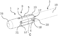
- FIG. 1 shows a perspective view of an uncoiled electrode portion formed from a multi-lumen tube, with an adapter according to the invention at one end of the uncoiled electrode portion,
- FIG. 2 shows a perspective view of an electrode according to the invention, wherein a coiled electrode portion with a total of four coiled electrical conductors is pushed over a plug-in region of the adapter shown in FIG. 1 in order to connect the coiled electrode portion to the uncoiled electrode portion likewise shown in FIG. 1 , and it will be seen here that each of the coiled conductors contacts each contact element of the adapter at least once,
- FIG. 3 shows a perspective view of an uncoiled electrode portion with an adapter region formed thereon, wherein the electrode portion and the adapter are formed by rolling up a flexible printed circuit board film into a cylindrical hollow body, here a pipe,
- FIG. 4 shows a perspective view of an electrode according to the invention whose coiled electrode portion with its four coiled electrical conductors is pushed over the adapter region, forming an adapter of the electrode, of the printed circuit board film of the uncoiled electrode portion rolled up to form the pipe, such that the coiled conductors encircle the adapter and the plug-in region of the adapter several times and touch each contact element of the adapter at least once,
- FIG. 5 shows a side view of a electrode which is comparable to the electrode shown in FIGS. 1 and 2 and which has a protective sheath that surrounds the adapter and the connection site between the two electrode portions, and
- FIG. 6 shows an enlarged view of the connection site between the two electrode portions from FIG. 5 .
- FIGS. 1 to 6 show different embodiments of an electromedical adapter.
- the adapter 1 is designated generally by 1 .
- elements that correspond in terms of their function retain corresponding reference numbers even when their configuration or shape differs.
- the electromedical adapters 1 shown in the figures are designed for the electrical connection of a coiled electrode portion 2 to an uncoiled electrode portion 3 of an electrode designated generally by 4 .
- the adapter 1 has at least one contact element 5 which is connectable to an uncoiled conductor 6 of the uncoiled electrode portion 3 and is arranged on a base body 7 of the adapter 1 in such a way that a coiled electrode portion 2 contacting the at least one contact element 5 in the position of use radially surrounds a longitudinal axis of the base body 7 of the adapter 1 with its at least one coiled conductor 8 .
- the coiled electrode portion 2 shown in FIGS. 2, 4, 5 and 6 has a total of four coiled conductors 8 .
- All the embodiments of the adapter 1 shown in FIGS. 1 to 6 each have a plug-in portion 9 on their base bodies 7 .
- the total of five contact elements 5 of the respective adapter 1 are arranged on an outer side of the plug-in portion 9 .
- the respective adapter 1 can be inserted with its plug-in portion 9 into an inner longitudinal cavity 10 , defined by the at least one coiled conductor 8 of the coiled electrode portion 2 , in an attachment end 11 of the coiled electrode portion 2 in order to contact the coiled electrode portion 2 and its coiled conductor 8 .
- the base body 7 of this adapter 1 has a socket for receiving an attachment end 11 of the coiled electrode portion 2 .
- this socket at least one contact element 5 is then arranged for contacting the at least one coiled conductor. If a plurality of contact elements 5 are present, they are preferably distributed uniformly about a longitudinal axis of the adapter 1 , its base body 7 or also its socket.
- the base bodies 7 of the adapters 1 shown are made of an electrically insulating material.
- the adapter 1 shown in FIGS. 1 and 2 has on its base body 7 , for each of the contact elements 5 , a respective groove-shaped retaining seat 12 . In each of the five retaining seats 12 in total, a respective contact element 5 is inserted. Each of the retaining seats 12 is arranged on the plug-in portion 9 of the adapter 1 .
- the retaining seats 12 are arranged correspondingly within the socket.
- the retaining seats 12 and the contact elements 5 are uniformly distributed about a longitudinal axis of the base body 7 of the adapter 1 and thus arranged on the adapter 1 in such a way that they can be easily contacted by the coiled conductors 8 of the coiled electrode portion 2 .
- the coiled conductors 8 surround the plug-in region 9 of the adapter 1 , and the contact elements 5 arranged thereon, several times, that is to say in an angular range of more than 360 degrees. As a result, each of the four coiled conductors 8 contacts each of the five contact elements 5 at least once. This promotes a reliable electrical connection of the electrode portions 2 and 3 .
- the retaining seats 12 of the adapter 1 from FIGS. 1 and 2 have end-face openings 13 . Through these end-face openings 13 , the contact elements 5 can first be inserted into the retaining seats 12 . Subsequently, the uncoiled conductors 6 of the uncoiled electrode portion 3 can be connected to the contact elements 5 through these end-face openings 13 .
- the contact elements 5 are contact sleeves which, in the position of use, are inserted into the retaining seats 12 of the adapter 1 .
- the contact elements 5 in the form of contact sleeves protrude radially outward from the retaining seats 12 and, for contacting the total of four coiled conductors 8 of the coiled electrode portion 2 , protrude outward beyond an outer circumference of the base body 7 of the adapter 1 .
- the adapter 1 has a plurality of contact elements 5 and retaining seats 12 uniformly distributed about a longitudinal axis of the adapter 1 and its base body 7 . According to FIGS. 3 and 4 , provision is also made, in the adapter 1 shown there, that a plurality of contact elements 5 are uniformly distributed about the longitudinal axis of this adapter 1 .
- both adapters 1 have as many retaining seats 12 or contact elements 5 as the uncoiled electrode portion 3 to be connected to the adapter 1 has uncoiled conductors 6 .
- a contact element 5 is available for each uncoiled conductor 6 of the uncoiled electrode portion 3 and, in the adapter 1 according to FIGS. 1 and 2 and also FIGS. 5 and 6 , a retaining seat 12 is also available in each case.
- the contact elements 5 formed as contact sleeves can each have a latching groove on the outside.
- the coiled electrode portion 2 When the coiled electrode portion 2 is located in the position of use on the adapter 1 , at least one of the four coiled conductors 8 of the coiled electrode portion 2 can engage in this latching groove 2 and be latched therein in the position of use.
- the base body 7 of the adapter 1 is produced from an adapter portion 14 of a flexible printed circuit board film 15 . This is done by the adapter portion 14 of the flexible printed circuit board film 15 being rolled up to form a cylindrical hollow body, here a pipe.
- the five contact elements 5 of this adapter 1 are contact surfaces formed on the adapter portion 14 .
- Each of the contact elements 5 formed as contact surfaces is electrically connected to a conductor track that forms an uncoiled conductor 6 of the uncoiled electrode portion 3 .
- the base bodies 7 of both adapters 1 are cylindrical and have a round or circular cross section.
- the base body 7 of the adapter shown in FIGS. 1 and 2 is provided with a chamfer or rounding 16 in its plug-in region 9 at a free end, which functions as a plug-in end. With the aid of this rounding 16 , the adapter 1 can be more easily introduced into the aforementioned inner longitudinal cavity 10 of the coiled electrode portion 2 .
- the base body 7 of the adapter 1 has a plug element 17 .
- a mating plug element 18 corresponding to the latter is arranged on the front end face of the uncoiled electrode portion 3 .
- the electromedical electrode 4 is configured as a stimulation electrode and, for example, can be used to deliver stimulation pulses, for example to the brain or another organ of a patient.
- the electromedical electrodes 4 shown in FIGS. 1 and 2 and also FIGS. 3 and 4 each comprise a coiled electrode portion 2 and an uncoiled electrode portion 3 .
- the coiled electrode portion 2 comprises a total of four coiled electrical conductors 8 , which together define the aforementioned inner longitudinal cavity 10 and enclose or encircle the latter several times.
- the uncoiled electrode portion 3 comprises at least one electrical conductor 6 , in the present illustrative embodiment five uncoiled electrical conductors 6 .
- the conductors 6 and 8 of the two electrode portions 2 are electrically connected to each other via one of the two adapters 1 already described above.
- FIGS. 2 and 4 and also FIGS. 5 and 6 illustrate that the coiled conductors 8 of the coiled electrode portion 2 engage externally over the respective plug-in region 9 of the adapter 1 for contacting the uncoiled electrode portion 3 with an attachment end 11 .
- the electromedical electrode 4 not shown in the figures, provision is made that the coiled portion 2 is plugged with an attachment end 11 into a socket of an electromedical adapter 1 and is thereby electrically connected to the uncoiled electrode portion 3 .
- the uncoiled electrode portion 3 is formed by a so-called multi-lumen tube 19 .
- the latter comprises, for each of the five uncoiled conductors 6 , an inner lumen 20 , in each of which an uncoiled conductor 6 extends.
- Each uncoiled conductor 6 of the uncoiled electrode portion 3 has a conductor end 21 protruding from the lumen tube 19 .
- Each conductor end 21 is connected to a respective contact element 5 of the adapter 1 . Since the contact elements 5 of the adapter 1 shown in FIGS. 1 and 2 are formed from contact sleeves, the conductor ends 21 can be pushed into the contact sleeves 5 and can be connected to the contact sleeves 5 by crimping the contact sleeves 5 .
- the coiled conductors 8 of the coiled electrode portion 2 can be connected to the sleeve-shaped contact elements 5 , for example by welding, gluing, soldering, bonding or wire bonding.
- Each coiled conductor 8 of the coiled electrode portion 2 contacts all of the total of five contact elements 5 of the adapter 1 . This applies to both of the illustrative embodiments of the adapters 1 and electrodes 4 shown in FIGS. 1 to 4 .
- a clear internal diameter ID of the coiled electrode portion 2 is smaller than a diameter of an imaginary enveloping circle (dot-dash line indicated at C in FIG. 1 ) which envelops the contact elements 5 located in the position of use on the outside of the plug-in region 9 of the respective adapter 1 .
- This has the consequence that the coiled electrode portion 2 engages over the adapter 1 and its contact elements 5 , in particular with its attachment end 11 , under radial pressure.
- This permits a force-fit connection between the coiled electrode portion 2 and the adapter 1 and also a reliable fit of the coiled electrode portion 2 on the adapter 1 and a stable connection of the two electrode portions 2 and 3 .
- the spreading that the coiled electrode portion 2 experiences in the region of its attachment end 11 can be clearly seen in the illustrative embodiment or electrode 4 shown in FIGS. 5 and 6 .
- the uncoiled electrode portion 3 is produced from a flexible printed circuit board film 15 which is rolled up to form a pipe 22 in the position of use.
- the printed circuit board film 15 has a total of five conductor tracks 23 which extend along the longitudinal extent of the printed circuit board film 15 and are oriented parallel to one another and to a longitudinal axis of the printed circuit board film 15 . These conductor tracks 23 function as uncoiled conductors 6 of this form of uncoiled electrode portion 3 .
- the uncoiled electrode portion 3 can contain in its interior a stabilizing support element and/or a stabilizing filler, for example of epoxy resin, particularly when the uncoiled electrode portion 3 is formed from a printed circuit board film 15 rolled up to form a pipe 22 .
- the adapter 1 in the electromedical electrode 4 shown in FIGS. 3 and 4 is formed from an adapter portion 14 of the printed circuit board film 15 of the uncoiled electrode portion 3 .
- the adapter 1 is automatically produced when the flexible printed circuit board film 15 is rolled up to produce the uncoiled electrode portion 3 .
- the adapter portion 14 is thus part of the printed circuit board film 15 and has, for each conductor track 23 , a respective contact surface electrically connected as contact element 5 to a conductor track 23 . This can be seen clearly in FIGS. 3 and 4 .
- this contact surface serving as contact element 5 can then be arranged on an outer side or also on an inner side of the pipe 22 thus produced. If the at least one contact surface 5 is arranged on an inner side of the printed circuit board film 15 rolled up to form a pipe 22 , this results in an adapter 1 with a socket which is suitable for receiving an attachment end 11 of a coiled electrode portion 2 to be connected to the adapter 1 .
- the at least one contact surface 5 is then arranged on a inner wall of the pipe 22 delimiting a socket of the adapter 1 for receiving the coiled electrode portion 2 .
- the electrode 4 can comprise more than the two electrode portions 2 and 3 shown in the figures. Particularly where a coiled electrode portion 2 meets an uncoiled electrode portion 3 or vice versa, an adapter 1 for connecting the two electrode portions 2 and 3 is then provided in each case.
- both electrode portions 2 and 3 have a plurality of electrode contacts 26 .
- the electrode contacts 26 one of the electrode portions 2 and 3 can be placed, for example, in a correspondingly configured connection socket of an electromedical pulse generator and attached thereto.
- the electrode contacts 26 of the corresponding electrode portion 2 or 3 arranged at the distal end of the electrode 4 , are then implanted, for example in a target site to which electrical impulses are intended to be delivered via the electrode contacts 26 .
- the embodiments of the electromedical electrode 4 shown in the figures can be used on an electromedical pulse generator.
- the electromedical electrodes 4 can be used particularly advantageously in an implantable electromedical stimulation device, for example an electromedical neurostimulator.
- a neurostimulator is used, for example, for the stimulation of specific regions of the brain.
- the neurostimulator is placed in the trunk of a patient, especially in the region of the clavicle or the chest.
- the target site to which the stimulation pulses are to be delivered by the electrode 4 then lies in the head of the patient.
- the electrode 4 according to the invention is used.
- an uncoiled electrode portion 3 can be routed in a section that is still located in the trunk of the patient. In the trunk, the electrode portion 3 is exposed to comparatively slight movements, such that an uncoiled electrode portion can be used here. In the neck region, which is by nature exposed to greater movements than the trunk, the electrode portion used can be a coiled electrode portion 2 , which is more flexible and more resistant to fracture than an uncoiled electrode portion 3 .
- an electrode 4 is used that is tailored to the particular application. This has the advantage that, with sufficient flexibility afforded by the coiled electrode portion 2 , a comparatively low total electrical resistance of the electrode 4 can be achieved through the uncoiled electrode portion 3 .
- an electromedical adapter 1 an electromedical electrode 4 and an electromedical pulse generator are provided.
- the adapter 1 in particular is provided which has at least one contact element 5 , the latter being contacted by a coiled electrode portion 2 of an electrode 4 in such a way that the coiled electrode portion 2 encloses, i.e. radially surrounds, a longitudinal axis of the base body 7 of the adapter 1 with its at least one coiled conductor 8 .
Landscapes
- Health & Medical Sciences (AREA)
- Animal Behavior & Ethology (AREA)
- Engineering & Computer Science (AREA)
- Biomedical Technology (AREA)
- Nuclear Medicine, Radiotherapy & Molecular Imaging (AREA)
- Radiology & Medical Imaging (AREA)
- Life Sciences & Earth Sciences (AREA)
- General Health & Medical Sciences (AREA)
- Public Health (AREA)
- Veterinary Medicine (AREA)
- Heart & Thoracic Surgery (AREA)
- Cardiology (AREA)
- Vascular Medicine (AREA)
- Electrotherapy Devices (AREA)
Abstract
Description
Claims (20)
Applications Claiming Priority (3)
| Application Number | Priority Date | Filing Date | Title |
|---|---|---|---|
| DE102017111280.4A DE102017111280B4 (en) | 2017-05-23 | 2017-05-23 | Electro-medical adapter, electromedical electrode and electromedical pulse generator |
| DE102017111280.4 | 2017-05-23 | ||
| PCT/EP2018/063564 WO2018215564A1 (en) | 2017-05-23 | 2018-05-23 | Electromedical adapter, electromedical electrode and electromedical pulse generator |
Publications (2)
| Publication Number | Publication Date |
|---|---|
| US20200230424A1 US20200230424A1 (en) | 2020-07-23 |
| US11484720B2 true US11484720B2 (en) | 2022-11-01 |
Family
ID=62567607
Family Applications (1)
| Application Number | Title | Priority Date | Filing Date |
|---|---|---|---|
| US16/615,512 Active 2038-11-01 US11484720B2 (en) | 2017-05-23 | 2018-05-23 | Electromedical adapter, electromedical electrode and electromedical pulse generator |
Country Status (4)
| Country | Link |
|---|---|
| US (1) | US11484720B2 (en) |
| EP (1) | EP3630266B1 (en) |
| DE (1) | DE102017111280B4 (en) |
| WO (1) | WO2018215564A1 (en) |
Families Citing this family (3)
| Publication number | Priority date | Publication date | Assignee | Title |
|---|---|---|---|---|
| DE102021100681A1 (en) | 2021-01-14 | 2022-07-14 | Osypka Ag | External electromedical pulse generator |
| DE102021100682B4 (en) | 2021-01-14 | 2024-06-13 | Osypka Ag | External electromedical pulse generator |
| DE102021104313A1 (en) * | 2021-02-23 | 2022-08-25 | Osypka Ag | Basic element for an electromedical device and electromedical device |
Citations (8)
| Publication number | Priority date | Publication date | Assignee | Title |
|---|---|---|---|---|
| US4161952A (en) | 1977-11-01 | 1979-07-24 | Mieczyslaw Mirowski | Wound wire catheter cardioverting electrode |
| DE4119222A1 (en) | 1991-06-11 | 1992-12-17 | Stoeckert Instr Gmbh | Adaptor for connection of pacemaker to electrode implanted in heart - has contact surface electrically connected to holding pin, insertable in electrode conductor, and fixed by clamp pieces |
| US5222506A (en) | 1991-07-29 | 1993-06-29 | Medtronic, Inc. | Implantable medical lead with electrical cross-over adaptor |
| WO2000051489A1 (en) | 1999-03-03 | 2000-09-08 | Endosonics Corporation | Flexible elongate member having one or more electrical contacts |
| US7292894B2 (en) | 2002-09-27 | 2007-11-06 | Medtronic, Inc. | Methods and apparatus for joining small diameter conductors within medical electrical leads |
| GB2456441A (en) | 2006-09-29 | 2009-07-22 | Hokuriku Elect Ind | Connector device for interconnecting circuit substrates |
| US20100057175A1 (en) | 2008-09-02 | 2010-03-04 | Boston Scientific Neuromodulation Corporation | Systems, devices, and methods for electrically coupling terminals to electrodes of electrical stimulation systems |
| US20150165217A1 (en) * | 2013-12-18 | 2015-06-18 | Medtronic, Inc. | Implantable medical electrical lead connector assemblies and methods of manufacture |
-
2017
- 2017-05-23 DE DE102017111280.4A patent/DE102017111280B4/en active Active
-
2018
- 2018-05-23 EP EP18730250.0A patent/EP3630266B1/en active Active
- 2018-05-23 US US16/615,512 patent/US11484720B2/en active Active
- 2018-05-23 WO PCT/EP2018/063564 patent/WO2018215564A1/en not_active Ceased
Patent Citations (8)
| Publication number | Priority date | Publication date | Assignee | Title |
|---|---|---|---|---|
| US4161952A (en) | 1977-11-01 | 1979-07-24 | Mieczyslaw Mirowski | Wound wire catheter cardioverting electrode |
| DE4119222A1 (en) | 1991-06-11 | 1992-12-17 | Stoeckert Instr Gmbh | Adaptor for connection of pacemaker to electrode implanted in heart - has contact surface electrically connected to holding pin, insertable in electrode conductor, and fixed by clamp pieces |
| US5222506A (en) | 1991-07-29 | 1993-06-29 | Medtronic, Inc. | Implantable medical lead with electrical cross-over adaptor |
| WO2000051489A1 (en) | 1999-03-03 | 2000-09-08 | Endosonics Corporation | Flexible elongate member having one or more electrical contacts |
| US7292894B2 (en) | 2002-09-27 | 2007-11-06 | Medtronic, Inc. | Methods and apparatus for joining small diameter conductors within medical electrical leads |
| GB2456441A (en) | 2006-09-29 | 2009-07-22 | Hokuriku Elect Ind | Connector device for interconnecting circuit substrates |
| US20100057175A1 (en) | 2008-09-02 | 2010-03-04 | Boston Scientific Neuromodulation Corporation | Systems, devices, and methods for electrically coupling terminals to electrodes of electrical stimulation systems |
| US20150165217A1 (en) * | 2013-12-18 | 2015-06-18 | Medtronic, Inc. | Implantable medical electrical lead connector assemblies and methods of manufacture |
Also Published As
| Publication number | Publication date |
|---|---|
| EP3630266B1 (en) | 2021-06-23 |
| DE102017111280A1 (en) | 2018-11-29 |
| EP3630266A1 (en) | 2020-04-08 |
| WO2018215564A1 (en) | 2018-11-29 |
| DE102017111280B4 (en) | 2018-12-27 |
| US20200230424A1 (en) | 2020-07-23 |
Similar Documents
| Publication | Publication Date | Title |
|---|---|---|
| US7299095B1 (en) | Electrical contact assembly | |
| US7974704B2 (en) | Lead body constructions for implantable medical electrical leads | |
| US7241180B1 (en) | Medical electrical lead connector assembly | |
| US8639340B2 (en) | Implantable medical lead connector sleeves | |
| CN105939756B (en) | Implantable medical electrical lead connector assembly and method of manufacture | |
| US11484720B2 (en) | Electromedical adapter, electromedical electrode and electromedical pulse generator | |
| US7571010B2 (en) | Cable electrode assembly for a lead terminal and method therefor | |
| US5569883A (en) | Joint for providing a secure connection between a wound element and a mating part in a body implantable lead assembly and method for making such joint | |
| US9800010B2 (en) | Implantable lead assembly | |
| CN103702712B (en) | Implantable passive medical lead | |
| CN106232181A (en) | Implantable medical electric feedthrough connector assembly and manufacture method | |
| US20190083795A1 (en) | Electrical connector cap for an implantable lead, implantable lead for use with said electrical connector cap, and implantable lead assembly | |
| US7822476B2 (en) | Electrode line and terminal part for an implantable heart stimulator | |
| CN104540545B (en) | Connector contacts for implantable devices | |
| US8442646B2 (en) | Forming conductive couplings in medical electrical leads | |
| US12496453B2 (en) | Implantable lead | |
| CN103702713B (en) | Implantable Active Medical Leads | |
| US20170333704A1 (en) | Leads for neurostimulation and method of assembling the same | |
| US20240222891A1 (en) | Pcba pig tail spring connector | |
| US20100280583A1 (en) | Electrode Element, Electrode Lead Comprising An Electrode Element, Method For The Production Of An Electrode Lead | |
| US20200155855A1 (en) | Implantable lead | |
| CN116785590A (en) | Connection structure and connection method of implantable pulse generator and pulse generator | |
| HK40008039B (en) | Implantable lead assembly comprising an electrical connector cap for an implantable lead and said lead |
Legal Events
| Date | Code | Title | Description |
|---|---|---|---|
| FEPP | Fee payment procedure |
Free format text: ENTITY STATUS SET TO UNDISCOUNTED (ORIGINAL EVENT CODE: BIG.); ENTITY STATUS OF PATENT OWNER: SMALL ENTITY |
|
| FEPP | Fee payment procedure |
Free format text: ENTITY STATUS SET TO SMALL (ORIGINAL EVENT CODE: SMAL); ENTITY STATUS OF PATENT OWNER: SMALL ENTITY |
|
| AS | Assignment |
Owner name: OSYPKA AG, GERMANY Free format text: ASSIGNMENT OF ASSIGNORS INTEREST;ASSIGNORS:GOTTSCHE, THORSTEN;GRAFE, MAIK;REEL/FRAME:051609/0856 Effective date: 20191219 |
|
| STPP | Information on status: patent application and granting procedure in general |
Free format text: APPLICATION DISPATCHED FROM PREEXAM, NOT YET DOCKETED |
|
| STPP | Information on status: patent application and granting procedure in general |
Free format text: DOCKETED NEW CASE - READY FOR EXAMINATION |
|
| STPP | Information on status: patent application and granting procedure in general |
Free format text: NON FINAL ACTION MAILED |
|
| STPP | Information on status: patent application and granting procedure in general |
Free format text: RESPONSE TO NON-FINAL OFFICE ACTION ENTERED AND FORWARDED TO EXAMINER |
|
| STPP | Information on status: patent application and granting procedure in general |
Free format text: FINAL REJECTION MAILED |
|
| STPP | Information on status: patent application and granting procedure in general |
Free format text: ADVISORY ACTION MAILED |
|
| STPP | Information on status: patent application and granting procedure in general |
Free format text: DOCKETED NEW CASE - READY FOR EXAMINATION |
|
| STPP | Information on status: patent application and granting procedure in general |
Free format text: NON FINAL ACTION MAILED |
|
| STPP | Information on status: patent application and granting procedure in general |
Free format text: NOTICE OF ALLOWANCE MAILED -- APPLICATION RECEIVED IN OFFICE OF PUBLICATIONS |
|
| STPP | Information on status: patent application and granting procedure in general |
Free format text: PUBLICATIONS -- ISSUE FEE PAYMENT VERIFIED |
|
| STCF | Information on status: patent grant |
Free format text: PATENTED CASE |