US11481882B2 - Systems and methods for selective replacement of objects in images - Google Patents
Systems and methods for selective replacement of objects in images Download PDFInfo
- Publication number
- US11481882B2 US11481882B2 US16/951,872 US202016951872A US11481882B2 US 11481882 B2 US11481882 B2 US 11481882B2 US 202016951872 A US202016951872 A US 202016951872A US 11481882 B2 US11481882 B2 US 11481882B2
- Authority
- US
- United States
- Prior art keywords
- image
- original image
- background
- original
- processing device
- Prior art date
- Legal status (The legal status is an assumption and is not a legal conclusion. Google has not performed a legal analysis and makes no representation as to the accuracy of the status listed.)
- Active, expires
Links
Images


Classifications
-
- G—PHYSICS
- G06—COMPUTING; CALCULATING OR COUNTING
- G06T—IMAGE DATA PROCESSING OR GENERATION, IN GENERAL
- G06T19/00—Manipulating 3D models or images for computer graphics
- G06T19/006—Mixed reality
-
- G—PHYSICS
- G06—COMPUTING; CALCULATING OR COUNTING
- G06T—IMAGE DATA PROCESSING OR GENERATION, IN GENERAL
- G06T5/00—Image enhancement or restoration
- G06T5/50—Image enhancement or restoration by the use of more than one image, e.g. averaging, subtraction
-
- G—PHYSICS
- G06—COMPUTING; CALCULATING OR COUNTING
- G06T—IMAGE DATA PROCESSING OR GENERATION, IN GENERAL
- G06T11/00—2D [Two Dimensional] image generation
- G06T11/60—Editing figures and text; Combining figures or text
-
- G—PHYSICS
- G06—COMPUTING; CALCULATING OR COUNTING
- G06T—IMAGE DATA PROCESSING OR GENERATION, IN GENERAL
- G06T3/00—Geometric image transformation in the plane of the image
- G06T3/40—Scaling the whole image or part thereof
- G06T3/4046—Scaling the whole image or part thereof using neural networks
-
- G—PHYSICS
- G06—COMPUTING; CALCULATING OR COUNTING
- G06T—IMAGE DATA PROCESSING OR GENERATION, IN GENERAL
- G06T7/00—Image analysis
- G06T7/10—Segmentation; Edge detection
- G06T7/11—Region-based segmentation
-
- G—PHYSICS
- G06—COMPUTING; CALCULATING OR COUNTING
- G06T—IMAGE DATA PROCESSING OR GENERATION, IN GENERAL
- G06T2207/00—Indexing scheme for image analysis or image enhancement
- G06T2207/20—Special algorithmic details
- G06T2207/20212—Image combination
- G06T2207/20216—Image averaging
Definitions
- the present disclosure relates generally to computer-based systems and methods for altering or editing digital images. More specifically, the present disclosure relates to systems and methods for selective replacement of objects in images, in order to generate a realistic image in an efficient manner.
- the systems and methods of the present disclosure solve these and other needs.
- an exemplary system for selective replacement of an object in an image includes an interface configured to receive as input an original image and a background image, and a processing device in communication with the interface.
- the processing device can be configured to process the original image using a neural network to detect one or more objects in the original image, generate a neural network mask of the original image for the one or more objects in the original image, generate a filtered original image including the original image without the one or more objects, generate a modulated background image including a replacement background based on the neural network mask, and generate a combined image including the filtered original image combined with the modulated background image.
- the original image can include a foreground and a background.
- the one or more objects can include the background of the original input. In some embodiments, the one or more objects include a sky as the background in the original image.
- the processing device can be configured to extract the foreground from the original image.
- the processing device can be configured to generate a refined mask for each pixel of the original image associated with the background.
- the processing device can be configured to generate a dilated or indented mask including a dilation or indentation from a border extending between the foreground and the background.
- the processing device can be configured to generate an interpolation grid corresponding to the foreground.
- the processing device can be configured to generate an extracted image including the original image with the foreground extracted based on the interpolation grid.
- the processing device can be configured to generate the filtered original image by extracting the foreground of the original image based on the interpolation grid.
- the processing device can be configured to generate a blended image, the blended image including a smooth transition between the filtered original image and the modulated background image.
- the processing device can be configured to generate a toned image, the toned image including the combined image with adjustment of tone within the combined image.
- the processing device can be configured to generate a tint unified image, the tint unified image including tint correction at edges between the filtered original image and the modulated background image.
- the processing device can be configured to adjust one or more characteristics of the filtered original image independently from one or more characteristics of the modulated background image.
- the interface can include an image selection section with the combined image and one or more additional original images.
- the interface can include a first submenu for selecting the combined image and copying the adjustments or enhancements applied to the combined image, and the interface can include a second submenu for selecting one or more of the additional original images and applying the copied adjustments or enhancements of the combined image to the selected one or more of the additional original images.
- an exemplary method for selective replacement of an object in an image can include receiving as input at an interface an original image and a background image, detecting one or more objects in the original image with a neural network, and generating a neural network mask of the original image for the one or more objects in the original image.
- the method can include generating a filtered original image, the filtered original image including the original image without the one or more objects.
- the method can include generating a modulated background image, the modulated background image including a replacement background based on the neural network mask.
- the method can include generating a combined image, the combined image including the filtered original image combined with the modulated background image.
- FIG. 8 is an exemplary image including a dilated mask in accordance with the present disclosure.
- FIG. 9 is an exemplary image including an interpolation grid in accordance with the present disclosure.
- FIG. 11 is an exemplary image with a foreground extracted in accordance with the present disclosure.
- FIG. 18 is an exemplary combined image in accordance with the present disclosure.
- FIG. 19 is an exemplary defocused image in accordance with the present disclosure.
- FIG. 20 is an exemplary combined image in accordance with the present disclosure.
- FIG. 21 is an exemplary horizon adjusted image in accordance with the present disclosure.
- FIG. 22 is an exemplary combined image in accordance with the present disclosure.
- FIG. 23 is an exemplary relit image in accordance with the present disclosure.
- FIG. 24 is an exemplary combined image in accordance with the present disclosure.
- FIG. 26 is an exemplary contrast adjusted image in accordance with the present disclosure.
- FIG. 28 is an exemplary defocused image in accordance with the present disclosure.
- FIG. 29 is an exemplary flipped image in accordance with the present disclosure.
- FIG. 30 is an exemplary combined image in accordance with the present disclosure.
- FIG. 31 is an exemplary blended image in accordance with the present disclosure.
- FIG. 32 is an exemplary combined image in accordance with the present disclosure.
- FIG. 33 is an exemplary blended image in accordance with the present disclosure.
- FIG. 34 is an exemplary input original image in accordance with the present disclosure.
- FIG. 35 is an exemplary combined image in accordance with the present disclosure.
- FIG. 36 is an exemplary tone image in accordance with the present disclosure.
- FIG. 37 is an exemplary user interface with settings for a warm color temperature in accordance with the present disclosure.
- FIG. 38 is an exemplary tone image in accordance with the present disclosure.
- FIG. 39 is an exemplary user interface with settings for a cool color temperature in accordance with the present disclosure.
- FIG. 41 is an exemplary combined image in accordance with the present disclosure.
- FIG. 42 is an exemplary haze adjusted image in accordance with the present disclosure.
- FIG. 45 is an exemplary user interface in accordance with the present disclosure.
- FIG. 46 is an exemplary user interface with an original input image in accordance with the present disclosure.
- FIG. 47 is an exemplary user interface with a combined image in accordance with the present disclosure.
- FIG. 51 is an exemplary image context menu of a user interface in accordance with the present disclosure.
- FIG. 52 is an exemplary image selection section of a user interface in accordance with the present disclosure.
- the system 100 can include a central computing system 112 for controlling the steps performed by the system 100 .
- the central computing system 112 can include the one or more processing devices 108 .
- the system 100 can include a user interface 114 (e.g., a device with a user interface), such as a user interface having a graphical user interface (GUI) 116 .
- the GUI 116 can be used to input data and/or instructions into the system 100 , and to output data and/or images to the user.
- the object segmentation network 120 can be used to identify and segment the object to be replaced in the original image (e.g., the sky).
- the multi-class segmentation network 122 can include a dataset with a large number of classes (e.g., trees, humans, buildings, or the like) to identify and segment specific objects in the original image to be extracted and combined with a replacement object (e.g., a replacement sky).
- the multi-class segmentation network 122 can be used for additional augmentations of the identified objects, e.g., random flip, random crop, random brightness, random rotation, affine transformation, combinations thereof, or the like.
- the system 100 can include a communication interface 124 configured to provide communication and/or transmission of data between the components of the system 100 shown in FIG. 1 .
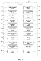
- FIG. 2 is a block diagram illustrating the software modules 106 of the system 100 in greater detail. Although illustrated as separate modules, in some embodiments, the modules can be combined or separated into one or more modules. For example, the modules can be combined into a single module and/or any of the modules can be distributed in the system 100 .
- the system 100 can include, e.g., a mask generation module 130 , a mask refinement module 132 , a mask dilation module 134 , an interpolation module 136 , an extraction module 138 , a filter image module 140 , a target background module 142 , an insertion module 144 , a horizon blending module 146 , a tone adjustment module 148 , a defocus module 150 , a horizon adjustment module 152 , a flip module 154 , an exposure module 156 , a tone module 158 , a background module 160 , a foreground module 162 , a mixing module 164 , a tinting unification module 166 , a haze module 165 , and a grain module 167 . Execution and operation of each of the modules 106 will be discussed in detail below with reference to sample images.
- FIG. 3 is a block diagram illustrating the database 104 of the system 100 in greater detail.
- the database 104 can electronically receive and/or store data corresponding to, e.g., input original images 170 , low resolution images 172 , neural network masks 174 , refined masks 176 , dilated masks 178 , interpolation grids 180 , extracted images 182 , details images 184 (e.g., filtered original images), background images 186 , exposure adjusted images 188 , tone adjusted images 190 , modulated background images 192 , combined images 194 , blended images 196 , toned images 198 , tint unified images 200 , final images 202 , defocused images 204 , horizon adjusted images 206 , flipped images 208 , adjusted images 210 , mixed images 212 , haze adjusted images 216 , grain adjusted images 218 , or the like.
- the data electronically received and/or stored in the database 104 will be discussed in detail below with reference to sample images
- the interpolation module can be executed by the processing device to generate an interpolation grid corresponding with the foreground of the original image.
- the extraction module can be executed by the processing device to generate an extracted image by extracting the foreground based on the interpolation grid.
- the filter module can be executed by the processing device to generate filtered original image including the foreground of the original image without the background.
- the target background module can be executed by the processing device to generate a modulated background image including a target background with the dilated mask.
- the insertion module can be executed by the processing device to generate a combined image by combining the filtered original image having the foreground of the original image with the modulated background image.
- the horizon blending module can be executed by the processing device to generate a blended image having a smooth transition between the filtered original image and the modulated background image.
- the tone adjustment module can be executed by the processing device to generate a toned image.
- an exemplary input original image 170 is provided.
- the image 170 can be received as input by the system 100 and electronically stored in the database 104 .
- Each input original image 170 includes a background 400 and a foreground 402 , each with one or more identifiable or segmentable objects.
- the background 400 in FIG. 5 can include the sky and clouds
- the foreground 402 can include the buildings, trees, grass, hills, people, or the like.
- the system 100 can generate a low resolution image 172 (see FIG. 6 ) of the input original image 170 for further processing to optimize or improve the operational speed of the system 100 in replacing one or more objects in the input original image 170 .
- the low resolution image 172 can be electronically stored in the database 104 .
- the mask generation module 130 can receive as input the low resolution image 172 (or the input original image 170 ), and is executed by the processing device 108 to generate a neural network mask 174 to be electronically stored in the database 104 .
- the mask generation module 130 can operate in combination with the neural network 118 to recognize and segment specific objects or portions of the image 172 .
- the object segmentation network 120 of the neural network 118 can be trained to detect, define and segment the sky as the background 400 of the image 172 .
- the mask generation module 130 and the neural network 118 thereby receive as input the image 172 and generate a probability mask (e.g., neural network mask 174 ) for each pixel of the image 172 in which the sky is detected.
- the mask refinement module 132 can receive as input the low resolution image 172 with the neural network mask 174 , and is executed by the processing device 108 to generate a refined mask 176 to be electronically stored in the database 104 .
- the neural network mask 174 can be refined using probabilistic color models.
- the indent/dilation distance or parameter defines the distance for indenting from the edges 404 and can be adjusted using a manual adjustment slider in the user interface 114 and/or automatically set by the system 100 .
- the system 100 can use a predetermined or default constant value for the indent/dilation distance.
- the mask dilation module 134 therefore ensures that the dilated mask 178 accurately captures the sky without capturing or overlapping with undesired objects of the foreground 402 .
- the dilated mask 178 ensures that only the object to be replaced is selected in the image 170 by capturing all pixels associated with the background.
- the interpolation module 136 can receive as input the low resolution image 172 and the dilated mask 178 , and is executed by the processing device 108 to generate an interpolation grid 180 .
- the interpolation grid 180 (e.g., a polygonal grid) can be constructed to interpolate or extrapolate the background (e.g., sky) using mean value coordinates interpolation.
- the interpolation grid 180 can be generated using the dilated mask 178 by identifying pixels along the edge or contour of the dilated mask 178 and smoothing the colors at each point associated with the interpolation grid 180 .
- the interpolation grid 180 provides a polygonal grid that identifies the foreground 402 of the image 172 .
- the generated interpolation grid 180 can be used by the system 100 to extract or erase the foreground 402 geometry from the background 400 to build a potentially endless background 400 (e.g., sky) behind the extracted foreground 402 .
- the extraction module 138 can receive as input the low resolution image 172 and the interpolation grid 180 , and is executed by the processing device 108 to extract the foreground 402 represented by the interpolation grid 180 from the image 172 .
- the result of such extraction is the extracted image 182 of FIG. 10 , which shows the interpolation grid 180 for clarity.
- the colors of the sky or background 400 under the objects represented by the interpolation grid 180 can be estimated by the system 100 to represent the potential sky under the extracted geometry.
- FIG. 11 shows the extracted image 182 without the interpolation grid 180 .
- the extracted image 182 thereby only includes the background 400 of the image 172 .
- the details image module 140 can receive as input the low resolution image 172 (or the input original image 170 ), the interpolation grid 180 with the foreground 402 data, and the extracted image 182 , and is executed by the processing device 108 to generate a details image 184 .
- the details image 184 includes only the deltas obtained from the differences between the image 172 and the extracted image 182 .
- the threshold value can be incorporated into the process as shown in Equation 10.
- the system 100 can set the threshold value as about 0.3.
- the threshold value can be controlled by a slider in the user interface 114 , including an incremental range from 0 to 1.
- the threshold value can be selected to be in a range of about 0.2 to about 0.5.
- the details image module 140 therefore “subtracts” the extracted image 182 from the image 170 or image 172 to obtain the details image 184 having only the extracted geometry of the foreground 402 .
- the extracted image 182 can be considered as a filtered original image when determining the difference between the extracted image 182 and the original image.
- the output details image 184 can be an analogue of the high-frequency band or details of the input original image 170 , including all elements or objects except for the original sky or background 400 . As described below, the details image 184 can be used to generate the refined mask 176 and illustrates the details transferred onto a new target or replacement sky by the modulation of Equation 12 (below).
- the target background module 142 can receive as input the DetailsBinaryMask (e.g., the refined mask 176 ) from Equation 11 and a background image 186 , and is executed by the processing device 108 to generate a target background image 214 .
- the target background image 214 is intended to underlie the details shown in the details image 184 as the new or replacement background.
- the refined mask 176 is used by the target background module 142 using a threshold value and applied to the input background image 186 to create a new or replacement background 406 .
- the threshold value can be incorporated into the process as shown in Equation 11 above. In some embodiments, the system 100 can set the threshold value as about 0.3.
- the threshold value can be controlled by a slider in the user interface 114 from and including 0 to 1. In some embodiments, the threshold value can be selected between about 0.2 to about 0.5.
- An edge or border 410 between the replacement background 406 and the underlying background 408 is generated based on the refined mask 176 to correspond with the edge or border of the image 172 to accommodate the details image 184 in a subsequent step.
- the underlying background 408 to be covered by the details shown in the details image 184 can be blended or blurred by the target background module 142 to have a similar color scheme as the replacement background 406 .
- the blended or blurred image can be superimposed on the target sky using the DetailsBinaryMask of Equation 12 to generate the target background image 214 .
- the underlying background 408 can be heavily blurred using a summed area table based on the target background image 214 , creating the effect of frosted glass.
- the summed area table or integral image can be used to blur with a different radius closer to the bottom of the image 214 , such that a stronger blur is gradually generated in the direction of the bottom of the image 214 .
- the new sky texture can be inserted such that the lower part of the sky touches or is in contact with the lower edge of the border 410 from the refined mask 176 , with the border 410 treated as the horizon for the image 214 .
- the system 100 can be used to rotate the horizon (thereby rotating the replacement background 406 ) to match the inclination of the sky or background 400 in the input original image 170 .
- the system 100 can be used to shift the horizon along the y-axis (e.g., vertically).
- the replacement background 406 generated by the target background module 142 ensures that details within the image receive the replacement background 406 . For example, rather than attempting to fill in gaps between leaves or branches of the tree in the image 170 , the system 100 generates a completely new background 406 on which the details of the image 170 can be placed.
- the insertion module 144 can receive as input the original image 170 (or image 172 ), the target background image 214 and the extracted image 182 , and is executed by the processing device 108 to generate a modulated background image 192 to place the details of the input original image 170 on the target or replacement sky.
- Details of the image are transferred because on the target background image 214 the relationship between DstSkyBox and SrcSkyBox in Equation 12 changes insignificantly and affects the overall brightness in the image, and the details are formed by multiplying by Src in Equation 12.
- the details image 184 is therefore used to generate the binary mask to identify the details to be transferred.
- the pixels are discolored such that their ratio does not distort the color of the target background image 214 .
- the matte areas of the refined mask 176 are discolored such that when the details are transferred to the target background image 214 , the colors are less distorted during modulation.
- the amountPreserveColor portion of Equation 15 is the parameter affecting the strength of the discoloration correction.
- the neural network mask 174 allows for a more accurate approach to detecting and identifying meditation with small details.
- the neural network 118 can be trained to detect different types of objects in the image 170 (e.g., vegetation, structures, people, or the like) and in instances where vegetation shines through stronger than other areas of the image, the neural network mask 174 allows for appropriate adjustment of the tone, resulting in a more realistic output.
- FIG. 16 provides a tone adjusted image 190 having a reduction of excess toning for a more realistic view of the image 192 .
- the tinting unification module 166 can receive as input the image 170 (or image 172 ), the modulated background image 192 , and the refined mask 176 from Equation 11, and is executed by the processing device to generate a tint unified image 200 .
- the tinting unification module 166 can correct or enhance the tinting discrepancies in areas at or near the border 410 between the replacement background and foreground. For example, the areas of the sky and foreground may not be well coordinated with each other after the mixing and enhancement steps discussed above. Hard spots may appear at the boundaries or border 410 of the two regions.
- the defocused image 202 includes a background 406 having a blurriness substantially aligned with the remaining focus of the image 202 .
- the force parameter associated with the intensity of the defocus effect can be selected by the operator via, e.g., a slider control at the user interface 114 , and/or automatically by the system 100 .
- FIG. 22 is a combined image 194 with a replacement background 406 . Due to the difference in lighting between the replacement background 406 and the foreground 402 , the combined image 194 may appear unrealistic. In such instances, the relighting module 168 can receive as input the combined image 194 , and is executed by the processing device 108 to generate a relit image 210 of FIG. 23 . The relighting of the combined image 194 can be adjusted by the user via the user interface 114 (e.g., one or more sliders of the interface) and/or automatically by the system 100 via the relighting module 168 . In the combined image 194 of FIG.
- the user interface 114 e.g., one or more sliders of the interface
- FIG. 25 is an image 188 with the replacement background 406 exposure adjusted without affecting the exposure of the foreground 402 .
- FIG. 26 is an image 188 with the foreground 402 contrast adjusted without affecting the contrast of the replacement background 406 .
- FIG. 27 is an image 188 with the foreground 402 exposure adjusted without affecting the exposure of the replacement background 406 . Adjustments to the foreground 402 and/or the background 406 can thereby be independently controlled to achieve realistic results.
- FIG. 34 is an input original image 170 having a background 400 and a foreground
- FIG. 36 is a combined image 194 having the foreground 402 and a replacement background 406 .
- the tone module 158 can be executed by the processing device 108 to generate a tone image 198 .
- FIG. 36 is a tone image 198 having a warmer color temperature of the replacement background 406 as compared to the replacement background 406 of the combined image 194 .
- FIG. 37 is a screenshot illustrating a user interface 114 of the system 100 with controls for setting color temperatures of the replacement background 406 of FIG. 36 .
- the controls or adjustments of the user interface 114 allow a user to achieve the warmer color temperature illustrated in FIG. 36 including, e.g., horizon blending, horizon position, relight scene, sky global, close gaps, sky local, sky defocus, sky temperature, sky exposure, combinations thereof, or the like.
- one or more of the controls can be in the form of a slider capable of being positioned at ⁇ 100% to 100%.
- the sky temperature control is adjusted to 100%.
- the adjustment of the user interface 114 can be controlled via user input at the user interface 114 and/or automatically by the system 100 .
- FIG. 1 is a screenshot illustrating a user interface 114 of the system 100 with controls for setting color temperatures of the replacement background 406 of FIG. 36 .
- the controls or adjustments of the user interface 114 allow a user to achieve the warmer color temperature illustrated in FIG. 36 including,
- additional adjustments or enhancements to the combined image 194 can be made by the system 100 .
- a strong difference may exist between the original image (e.g., the original foreground 402 ) and the replacement background 406 , with such differences being noticeable and resulting in an unrealistic image 194 .
- a real sky includes at least some haze.
- the system 100 can include a setting for adjusting the haze of the daytime replacement sky.
- FIG. 41 is a combined image 194 without haze added to the replacement background 406 . Relative to the foreground 402 , the contrast and color of the replacement background 406 can appear too different for a realistic image.
- the processing device can execute the haze module 165 to receive as input the combined image 194 , and generate the haze adjusted image 216 of FIG. 42 .
- the haze module 165 can adjust the haze and/or brightness of the combined image 194 to output a more realistic image 216 .
- the haze module 165 can create a first layer (e.g., Layer 0) filled with a haze color, such as pure which in the example of FIG. 42 .
- a second layer e.g., Layer 1
- the transparency of the replacement background 406 can be set as about 70%, although the transparency value can be adjusted or customized by the system 100 and/or the user based on the images involved.
- FIGS. 43 and 44 are additional examples of combined images 194 and haze adjusted images 216 after application of a haze to the replacement background 406 .
- the processing device 108 can execute a grain module 167 to receive as input the combined image 194 , and generate the grain adjusted image 218 .
- the grain module 167 can add texture on the palate with noise to match noise of the original image 170 . Therefore, zooming in on the grain adjusted image 218 provides a substantially similar texture for the foreground 402 and the replacement background 406 .
- FIG. 45 is a screenshot illustrating a user interface 114 in accordance with the present disclosure.
- the user interface 114 includes an image selection section 420 including multiple imported images for potential editing.
- the user interface 114 includes an image section 422 including a single image to be edited by the system 100 .
- the user interface 114 includes an adjustment section 424 including multiple controls in the form of, e.g., sliders, check boxes, input boxes, preset adjustments, combinations thereof, or the like, for various setting controls associated with the image in the image section 422 .
- FIG. 46 is a screenshot illustrating a user interface 114 including an original input image 170 in the image section 422 , the original input image 170 including a foreground 402 and an original background 400 sky.
- FIG. 47 is a screenshot illustrating the user interface 114 including a combined image 194 including the foreground 402 and a replacement background 406 sky.
- FIG. 48 is a screenshot illustrating a detailed view of the adjustment section 424 with characteristic settings for the replacement background 406 .
- the adjustment section 424 includes a background selection section 426 with a drop-down menu that can be used to select from a list of different replacement backgrounds. For example, rather than the background shown in FIG.
- the background selection section 426 can be used to select a different replacement background (see, e.g., FIG. 22 ).
- the adjustment section 424 includes slider selectors for gradual selection of horizon blending 428 , horizon position 430 , relight scene 432 , sky global 434 , close gaps 438 , sky local 440 , sky defocus 442 , sky temperature 444 , and sky exposure 446 .
- the sky local 440 setting can be used to fill in areas of the image adjacent to edges of the sky if gaps exist after the background replacement process.
- the close gaps 438 setting can be used to correct, remove or enhance artifact occurrences on the horizon or on the foreground 402 if such artifacts occur during the background replacement process.
- the adjustment section 424 includes an advanced settings section 434 , a checkbox for flip sky 450 , and an edit mask section 448 .
- the edit mask section 448 can be used to adjust the neural network mask 174 .
- the edit mask section 448 can allow a user to manually adjust the replacement sky or background 406 (e.g., by selecting and dragging one or more portions of the neural network mask 174 ) to adjust where the replacement background 406 is placed.
- the edit mask section 448 can be used to manually remove one or more portions of the replacement background 406 and/or add the replacement background 406 to one or more portions of the image where the system 100 did not previously add the replacement background 406 .
- the edit mask section 448 can provide the user with a brush to draw or select a section of the image that should be included or excluded from the mask.
- the edit mask section 448 can be used to manually fix or edit the mask generated by the system 100 .
- the replacement background 406 can be adjusted by, e.g., shifting the horizon position along a vertical y-axis (see, e.g., FIG. 21 ).
- FIG. 49 is a screenshot illustrating a detailed view of an image context menu 452 of the user interface 114 .
- the image context menu 452 of FIG. 50 includes an edited combined image 194 with a replacement background and multiple input original images 170 with original backgrounds.
- a submenu 454 can be selected by the user by right-clicking on the combined image 194 , choosing adjustments, and copy adjustments to copy the adjustments (including the replacement background) of the combined image 194 .
- the user can select the input original images 170 in the image context menu 452 for which the same adjustments will be applied and, as shown in FIG. 50 , right-clicking on the selected images 170 generates a submenu 456 .
- FIG. 52 is a screenshot illustrating a detailed view of an image selection section 420 of the user interface 114 including a combined image 194 with a replacement background and multiple input original images 170 with original backgrounds.
- a submenu 454 (see, e.g., FIG. 49 ) can be generated in a similar manner as described above in the image selection section 420 to copy adjustments or enhancements of the combined image 194 .
- the desired original images 170 can be selected in the image selection section 420 and the submenu 456 (see, e.g., FIG. 50 ) can be used to copy, apply or sync the adjustments/enhancements to the selected original images 170 .
- FIG. 53 is a screenshot illustrating the image selection section 420 with the adjustments copied or synced to two original images 170 . The process of copying the adjustments or enhancements to additional original images 170 in the system can thereby be provided in an efficient and convenient manner.
- FIG. 54 is a block diagram of a computing device 500 (e.g., a mobile device, a smart device, a computer, or the like) in accordance with exemplary embodiments of the present disclosure.
- the computing device 500 includes one or more non-transitory computer-readable media for storing one or more computer-executable instructions or software for implementing exemplary embodiments.
- the non-transitory computer-readable media may include, but are not limited to, one or more types of hardware memory, non-transitory tangible media (for example, one or more magnetic storage disks, one or more optical disks, one or more flash drives), and the like.
- memory 506 included in the computing device 500 may store computer-readable and computer-executable instructions or software for implementing exemplary embodiments of the present disclosure (e.g., instructions for operating the camera, instructions for operating the modules, instructions for operating the database, instructions for operating the processing device, instructions for operating the communication interface, instructions for operating the user interface, instructions for operating the central computing system, instructions for operating the neural network, combinations thereof, or the like).
- instructions for operating the camera e.g., instructions for operating the camera, instructions for operating the modules, instructions for operating the database, instructions for operating the processing device, instructions for operating the communication interface, instructions for operating the user interface, instructions for operating the central computing system, instructions for operating the neural network, combinations thereof, or the like.
- the computing device 500 also includes configurable and/or programmable processor 502 and associated core 504 , and optionally, one or more additional configurable and/or programmable processor(s) 502 ′ and associated core(s) 504 ′ (for example, in the case of computer systems having multiple processors/cores), for executing computer-readable and computer-executable instructions or software stored in the memory 506 and other programs for controlling system hardware.
- Processor 502 and processor(s) 502 ′ may each be a single core processor or multiple core ( 504 and 504 ′) processor.
- Virtualization may be employed in the computing device 500 so that infrastructure and resources in the computing device 500 may be shared dynamically.
- a virtual machine 514 may be provided to handle a process running on multiple processors so that the process appears to be using only one computing resource rather than multiple computing resources. Multiple virtual machines may also be used with one processor.
- Memory 506 may include a computer system memory or random access memory, such as DRAM, SRAM, EDO RAM, and the like. Memory 506 may include other types of memory as well, or combinations thereof.
- a user may interact with the computing device 500 through a visual display device 518 (e.g., a personal computer, a mobile smart device, or the like), such as a computer monitor, which may display at least one user interface 520 (e.g., a graphical user interface) that may be provided in accordance with exemplary embodiments.
- the computing device 500 may include other I/O devices for receiving input from a user, for example, a camera, a keyboard, microphone, or any suitable multi-point touch interface 508 , a pointing device 510 (e.g., a mouse), or the like.
- the input interface 508 and/or the pointing device 510 may be coupled to the visual display device 518 .
- the computing device 500 may include other suitable conventional I/O peripherals.
- the computing device 500 can include a network interface 512 configured to interface via at least one network device 522 with one or more networks, for example, a Local Area Network (LAN), a Wide Area Network (WAN) or the Internet through a variety of connections including, but not limited to, standard telephone lines, LAN or WAN links (for example, 802.11, T1, T3, 56 kb, X.25), broadband connections (for example, ISDN, Frame Relay, ATM), wireless connections, controller area network (CAN), or some combination of any or all of the above.
- networks for example, a Local Area Network (LAN), a Wide Area Network (WAN) or the Internet through a variety of connections including, but not limited to, standard telephone lines, LAN or WAN links (for example, 802.11, T1, T3, 56 kb, X.25), broadband connections (for example, ISDN, Frame Relay, ATM), wireless connections, controller area network (CAN), or some combination of any or all of the above.
- LAN Local Area Network
- WAN Wide Area Network
- CAN controller area
- the computing device 500 may be any computer system, such as a workstation, desktop computer, server, laptop, handheld computer, tablet computer (e.g., the tablet computer), mobile computing or communication device (e.g., the smart phone communication device), an embedded computing platform, or other form of computing or telecommunications device that is capable of communication and that has sufficient processor power and memory capacity to perform the operations described herein.
- a workstation desktop computer, server, laptop, handheld computer, tablet computer (e.g., the tablet computer), mobile computing or communication device (e.g., the smart phone communication device), an embedded computing platform, or other form of computing or telecommunications device that is capable of communication and that has sufficient processor power and memory capacity to perform the operations described herein.
- FIG. 55 is a block diagram of an exemplary system for selective replacement of objects in images environment 600 in accordance with exemplary embodiments of the present disclosure.
- the environment 600 can include servers 602 , 604 configured to be in communication with one or more cameras 606 , one or more modules 608 , at least one processing device 610 , a user interface 612 , and a central computing system 614 via a communication platform 620 , which can be any network over which information can be transmitted between devices communicatively coupled to the network.
- the communication platform 620 can be the Internet, Intranet, virtual private network (VPN), wide area network (WAN), local area network (LAN), and the like.
- the communication platform 620 can be part of a cloud environment.
- the databases 616 , 618 can be incorporated into at least one of the servers 602 , 604 .
- the databases 616 , 618 can store data relating to the database 104 , and such data can be distributed over multiple databases 616 , 618 .
Abstract
Description
float skyHist [N] [N] [N] (1)
float nonSkyHist [N] [N] [N] (2)
Int x=pixel.r*(N−1) (3)
Int y=pixel.g*(N−1) (4)
Int z=pixel.b*(N−1) (5)
where N is a dimension equal to 8. Two histograms can be used to count pixels under the
refinedIsSkyPixel=skyHist [z] [y] [x]>nonSkyHist [z] [y] [x] (6)
OriginalDetailsMap=abs(OriginalImage−SrcSkyBox) (7)
where OriginalImage is either the
dp=RGB2LAB(OriginalImage)−RGB2LAB(SrcSkyBox) (8)
OriginalDetailsMap=sqrt(dp.r*dp.r+dp.g*dp.g+dp.b*dp.b) (9)
where OriginalImage is the original image, and SrcSkyBox is the original sky with the erased foreground objects (e.g., the extracted image 182).
amount=0.16*(isPlant ( )? 2.8:1.0)*amountThreshold (10)
DetailsBinaryMask=OriginalDetaiilsMap<amount? 1:0 (11)
where isPlant ( ) is a function that returns the mask of probabilities of vegetation received from the
Dst=Src*DstSkyBox/SrcSkyBox (12)
where DstSkyBox is the
float toGray(Pixel p) {return sqrt(p.r*p.r+p.g*p.g+p.b*p.b)/3;} (13)
Pixel dp=Src−SkyBoxSrc;
float v=toGray(dp*dp);
v=clampValue(v*30);
Interpolation function: lerp(a, b, amount) {return a+(b−a)*amount;}
float graySrc=toGray(SkyBoxSrc); (14)
SkyBoxSrc=lerp(SkyBoxSrc, lerp(SkyBoxSrc, Pixel(graySrc), v), amountPreserveColor)
float grayDst=toGray(SkyBoxDst); (15)
SkyDst=lerp(SkyBoxDst, lerp(SkyBoxDst, Pixel(grayDst), v), amountPreserveColor)
where v represents the details mask, Src represents the input
Claims (20)
Priority Applications (2)
| Application Number | Priority Date | Filing Date | Title |
|---|---|---|---|
| US16/951,872 US11481882B2 (en) | 2019-11-18 | 2020-11-18 | Systems and methods for selective replacement of objects in images |
| US17/969,926 US20230045751A1 (en) | 2019-11-18 | 2022-10-20 | Systems and methods for selective replacement of objects in images |
Applications Claiming Priority (2)
| Application Number | Priority Date | Filing Date | Title |
|---|---|---|---|
| US201962936845P | 2019-11-18 | 2019-11-18 | |
| US16/951,872 US11481882B2 (en) | 2019-11-18 | 2020-11-18 | Systems and methods for selective replacement of objects in images |
Related Child Applications (1)
| Application Number | Title | Priority Date | Filing Date |
|---|---|---|---|
| US17/969,926 Continuation US20230045751A1 (en) | 2019-11-18 | 2022-10-20 | Systems and methods for selective replacement of objects in images |
Publications (2)
| Publication Number | Publication Date |
|---|---|
| US20210150682A1 US20210150682A1 (en) | 2021-05-20 |
| US11481882B2 true US11481882B2 (en) | 2022-10-25 |
Family
ID=75909571
Family Applications (2)
| Application Number | Title | Priority Date | Filing Date |
|---|---|---|---|
| US16/951,872 Active 2041-04-21 US11481882B2 (en) | 2019-11-18 | 2020-11-18 | Systems and methods for selective replacement of objects in images |
| US17/969,926 Abandoned US20230045751A1 (en) | 2019-11-18 | 2022-10-20 | Systems and methods for selective replacement of objects in images |
Family Applications After (1)
| Application Number | Title | Priority Date | Filing Date |
|---|---|---|---|
| US17/969,926 Abandoned US20230045751A1 (en) | 2019-11-18 | 2022-10-20 | Systems and methods for selective replacement of objects in images |
Country Status (1)
| Country | Link |
|---|---|
| US (2) | US11481882B2 (en) |
Families Citing this family (6)
| Publication number | Priority date | Publication date | Assignee | Title |
|---|---|---|---|---|
| US10742899B1 (en) | 2017-08-30 | 2020-08-11 | Snap Inc. | Systems, devices, and methods for image enhancement |
| US11651477B2 (en) * | 2020-08-07 | 2023-05-16 | Adobe Inc. | Generating an image mask for a digital image by utilizing a multi-branch masking pipeline with neural networks |
| US11393100B2 (en) | 2020-08-07 | 2022-07-19 | Adobe Inc. | Automatically generating a trimap segmentation for a digital image by utilizing a trimap generation neural network |
| US11776184B2 (en) * | 2020-10-18 | 2023-10-03 | Adobe, Inc. | Sky replacement |
| US20220392032A1 (en) * | 2021-06-02 | 2022-12-08 | f8 Real Estate Media, LLC | Classification-based image merging, tuning, correction, and replacement |
| US20230368339A1 (en) * | 2022-05-13 | 2023-11-16 | Adobe Inc. | Object class inpainting in digital images utilizing class-specific inpainting neural networks |
Citations (5)
| Publication number | Priority date | Publication date | Assignee | Title |
|---|---|---|---|---|
| US20070189615A1 (en) * | 2005-08-12 | 2007-08-16 | Che-Bin Liu | Systems and Methods for Generating Background and Foreground Images for Document Compression |
| US20160035102A1 (en) * | 2014-07-31 | 2016-02-04 | Siemens Aktiengesellschaft | Method and system for computing digital tomosynthesis images |
| US20200151860A1 (en) * | 2018-11-13 | 2020-05-14 | Adobe Inc. | Intelligent identification of replacement regions for mixing and replacing of persons in group portraits |
| US20210019453A1 (en) * | 2019-07-15 | 2021-01-21 | Ke.Com (Beijing) Technology Co., Ltd. | Artificial intelligence systems and methods for interior design |
| US20210097691A1 (en) * | 2019-09-30 | 2021-04-01 | Nvidia Corporation | Image generation using one or more neural networks |
Family Cites Families (2)
| Publication number | Priority date | Publication date | Assignee | Title |
|---|---|---|---|---|
| US10867416B2 (en) * | 2017-03-10 | 2020-12-15 | Adobe Inc. | Harmonizing composite images using deep learning |
| US10613726B2 (en) * | 2017-12-22 | 2020-04-07 | Adobe Inc. | Removing and replacing objects in images according to a directed user conversation |
-
2020
- 2020-11-18 US US16/951,872 patent/US11481882B2/en active Active
-
2022
- 2022-10-20 US US17/969,926 patent/US20230045751A1/en not_active Abandoned
Patent Citations (5)
| Publication number | Priority date | Publication date | Assignee | Title |
|---|---|---|---|---|
| US20070189615A1 (en) * | 2005-08-12 | 2007-08-16 | Che-Bin Liu | Systems and Methods for Generating Background and Foreground Images for Document Compression |
| US20160035102A1 (en) * | 2014-07-31 | 2016-02-04 | Siemens Aktiengesellschaft | Method and system for computing digital tomosynthesis images |
| US20200151860A1 (en) * | 2018-11-13 | 2020-05-14 | Adobe Inc. | Intelligent identification of replacement regions for mixing and replacing of persons in group portraits |
| US20210019453A1 (en) * | 2019-07-15 | 2021-01-21 | Ke.Com (Beijing) Technology Co., Ltd. | Artificial intelligence systems and methods for interior design |
| US20210097691A1 (en) * | 2019-09-30 | 2021-04-01 | Nvidia Corporation | Image generation using one or more neural networks |
Non-Patent Citations (8)
| Title |
|---|
| "Dilation (morphology)", Wikipedia entry, archived Oct. 2, 2019: https://web.archive.org/web/20191002155651/https://en.wikipedia.org/wiki/Dilation_(morphology). |
| "Graph Transform Tool", GitHub Tensorflow Tools README file, archived Nov. 4, 2018: https://web.archive.org/web/20181104111318/https://github.com/tensorflow/tensorflow/blob/master/tensorflow/tools/graph_transforms/README.md. |
| Chen et al., "Encoder-Decoder with Atrous Separable Convolution for Semantic Image Segmentation", in Lecture Notes in Computer Science: Computer Vision—ECCV 2018, pp. 833-851. |
| Farbman et al., "Coordinates for Instant Image Cloning", in SIGGRAPH '09: ACM SIGGRAPH 2009 papers, Jul. 2009, Article No. 67, pp. 1-9. |
| He et al., "Guided Image Filtering", IEEE Transactions on Pattern Analysis and Machine Intelligence (vol. 35, Issue: 6, Jun. 2013), pp. 1397-1409. |
| He et al., "Guided Image Filtering", Proceedings of the European Conference on Computer Vision (ECCV) 2010, pp. 1-14. |
| Paris et al., "Local Laplacian Filters: Edge-aware Image Processing with a Laplacian Pyramid", ACM Transactions on Graphics (Proceedings of SIGGRAPH 2011), Communications of the ACM (Mar. 2015, vol. 58, No. 3). |
| Sandler et al., "MobileNetV2: Inverted Residuals and Linear Bottlenecks", Proceedings of the IEEE Conference on Computer Vision and Pattern Recognition (CVPR) 2 018, pp. 4510-4520. |
Also Published As
| Publication number | Publication date |
|---|---|
| US20210150682A1 (en) | 2021-05-20 |
| US20230045751A1 (en) | 2023-02-09 |
Similar Documents
| Publication | Publication Date | Title |
|---|---|---|
| US11481882B2 (en) | Systems and methods for selective replacement of objects in images | |
| Wright | Digital compositing for film and vídeo: Production Workflows and Techniques | |
| CN106548455B (en) | Apparatus and method for adjusting brightness of image | |
| Wang et al. | Gladnet: Low-light enhancement network with global awareness | |
| US11042990B2 (en) | Automatic object replacement in an image | |
| US8644638B2 (en) | Automatic localized adjustment of image shadows and highlights | |
| Gijsenij et al. | Computational color constancy: Survey and experiments | |
| US11651480B2 (en) | Systems and methods for selective enhancement of objects in images | |
| CA2442603C (en) | Digital composition of a mosaic image | |
| US8331721B2 (en) | Automatic image correction providing multiple user-selectable options | |
| Akers et al. | Conveying shape and features with image-based relighting | |
| EP2898668B1 (en) | System for photograph enhancement by user controlled local image enhancement | |
| US11727543B2 (en) | Systems and methods for content-aware enhancement of images | |
| US11750935B2 (en) | Systems and methods of image enhancement | |
| CN113039576A (en) | Image enhancement system and method | |
| Liu et al. | Progressive complex illumination image appearance transfer based on CNN | |
| US20230281764A1 (en) | Systems and methods for selective enhancement of skin features in images | |
| US8942476B1 (en) | Saturation varying and lighting independent color color control for computer graphics | |
| Baek et al. | WYSIWYG computational photography via viewfinder editing | |
| US8396290B1 (en) | Saturation varying color space | |
| JP2020135653A (en) | Video image correction device and program | |
| US20230351560A1 (en) | Systems and Methods for Manipulation of Shadows on Portrait Image Frames | |
| CN109584172A (en) | Backlight compensation method and device based on the fuzzy learning machine that transfinites of iteration | |
| Vazquez-Corral et al. | Perceptually-based restoration of backlit images | |
| KR102606373B1 (en) | Method and apparatus for adjusting facial landmarks detected in images |
Legal Events
| Date | Code | Title | Description |
|---|---|---|---|
| AS | Assignment |
Owner name: SHINYFIELDS LIMITED, CYPRUS Free format text: ASSIGNMENT OF ASSIGNORS INTEREST;ASSIGNORS:SYTNIK, DMITRY;FROLOV, ANDREY;REEL/FRAME:054412/0044 Effective date: 20201116 |
|
| FEPP | Fee payment procedure |
Free format text: ENTITY STATUS SET TO UNDISCOUNTED (ORIGINAL EVENT CODE: BIG.); ENTITY STATUS OF PATENT OWNER: LARGE ENTITY |
|
| FEPP | Fee payment procedure |
Free format text: PETITION RELATED TO MAINTENANCE FEES GRANTED (ORIGINAL EVENT CODE: PTGR); ENTITY STATUS OF PATENT OWNER: LARGE ENTITY |
|
| STPP | Information on status: patent application and granting procedure in general |
Free format text: DOCKETED NEW CASE - READY FOR EXAMINATION |
|
| STPP | Information on status: patent application and granting procedure in general |
Free format text: NOTICE OF ALLOWANCE MAILED -- APPLICATION RECEIVED IN OFFICE OF PUBLICATIONS |
|
| STPP | Information on status: patent application and granting procedure in general |
Free format text: PUBLICATIONS -- ISSUE FEE PAYMENT VERIFIED |
|
| STCF | Information on status: patent grant |
Free format text: PATENTED CASE |