US11480485B2 - Pressure measurement device having piezostrictive and magnetostrictive measurement units - Google Patents
Pressure measurement device having piezostrictive and magnetostrictive measurement units Download PDFInfo
- Publication number
- US11480485B2 US11480485B2 US17/158,201 US202117158201A US11480485B2 US 11480485 B2 US11480485 B2 US 11480485B2 US 202117158201 A US202117158201 A US 202117158201A US 11480485 B2 US11480485 B2 US 11480485B2
- Authority
- US
- United States
- Prior art keywords
- pressure
- piezostrictive
- receiving region
- pressure receiving
- magnetostrictive
- Prior art date
- Legal status (The legal status is an assumption and is not a legal conclusion. Google has not performed a legal analysis and makes no representation as to the accuracy of the status listed.)
- Active, expires
Links
Images


Classifications
-
- G—PHYSICS
- G01—MEASURING; TESTING
- G01L—MEASURING FORCE, STRESS, TORQUE, WORK, MECHANICAL POWER, MECHANICAL EFFICIENCY, OR FLUID PRESSURE
- G01L9/00—Measuring steady of quasi-steady pressure of fluid or fluent solid material by electric or magnetic pressure-sensitive elements; Transmitting or indicating the displacement of mechanical pressure-sensitive elements, used to measure the steady or quasi-steady pressure of a fluid or fluent solid material, by electric or magnetic means
- G01L9/0041—Transmitting or indicating the displacement of flexible diaphragms
- G01L9/0042—Constructional details associated with semiconductive diaphragm sensors, e.g. etching, or constructional details of non-semiconductive diaphragms
-
- G—PHYSICS
- G01—MEASURING; TESTING
- G01L—MEASURING FORCE, STRESS, TORQUE, WORK, MECHANICAL POWER, MECHANICAL EFFICIENCY, OR FLUID PRESSURE
- G01L15/00—Devices or apparatus for measuring two or more fluid pressure values simultaneously
-
- G—PHYSICS
- G01—MEASURING; TESTING
- G01L—MEASURING FORCE, STRESS, TORQUE, WORK, MECHANICAL POWER, MECHANICAL EFFICIENCY, OR FLUID PRESSURE
- G01L9/00—Measuring steady of quasi-steady pressure of fluid or fluent solid material by electric or magnetic pressure-sensitive elements; Transmitting or indicating the displacement of mechanical pressure-sensitive elements, used to measure the steady or quasi-steady pressure of a fluid or fluent solid material, by electric or magnetic means
- G01L9/0001—Transmitting or indicating the displacement of elastically deformable gauges by electric, electro-mechanical, magnetic or electro-magnetic means
- G01L9/0004—Transmitting or indicating the displacement of elastically deformable gauges by electric, electro-mechanical, magnetic or electro-magnetic means using variations in inductance
-
- G—PHYSICS
- G01—MEASURING; TESTING
- G01L—MEASURING FORCE, STRESS, TORQUE, WORK, MECHANICAL POWER, MECHANICAL EFFICIENCY, OR FLUID PRESSURE
- G01L9/00—Measuring steady of quasi-steady pressure of fluid or fluent solid material by electric or magnetic pressure-sensitive elements; Transmitting or indicating the displacement of mechanical pressure-sensitive elements, used to measure the steady or quasi-steady pressure of a fluid or fluent solid material, by electric or magnetic means
- G01L9/0041—Transmitting or indicating the displacement of flexible diaphragms
- G01L9/0051—Transmitting or indicating the displacement of flexible diaphragms using variations in ohmic resistance
- G01L9/0052—Transmitting or indicating the displacement of flexible diaphragms using variations in ohmic resistance of piezoresistive elements
-
- G—PHYSICS
- G01—MEASURING; TESTING
- G01L—MEASURING FORCE, STRESS, TORQUE, WORK, MECHANICAL POWER, MECHANICAL EFFICIENCY, OR FLUID PRESSURE
- G01L9/00—Measuring steady of quasi-steady pressure of fluid or fluent solid material by electric or magnetic pressure-sensitive elements; Transmitting or indicating the displacement of mechanical pressure-sensitive elements, used to measure the steady or quasi-steady pressure of a fluid or fluent solid material, by electric or magnetic means
- G01L9/02—Measuring steady of quasi-steady pressure of fluid or fluent solid material by electric or magnetic pressure-sensitive elements; Transmitting or indicating the displacement of mechanical pressure-sensitive elements, used to measure the steady or quasi-steady pressure of a fluid or fluent solid material, by electric or magnetic means by making use of variations in ohmic resistance, e.g. of potentiometers, electric circuits therefor, e.g. bridges, amplifiers or signal conditioning
- G01L9/06—Measuring steady of quasi-steady pressure of fluid or fluent solid material by electric or magnetic pressure-sensitive elements; Transmitting or indicating the displacement of mechanical pressure-sensitive elements, used to measure the steady or quasi-steady pressure of a fluid or fluent solid material, by electric or magnetic means by making use of variations in ohmic resistance, e.g. of potentiometers, electric circuits therefor, e.g. bridges, amplifiers or signal conditioning of piezo-resistive devices
-
- G—PHYSICS
- G01—MEASURING; TESTING
- G01L—MEASURING FORCE, STRESS, TORQUE, WORK, MECHANICAL POWER, MECHANICAL EFFICIENCY, OR FLUID PRESSURE
- G01L9/00—Measuring steady of quasi-steady pressure of fluid or fluent solid material by electric or magnetic pressure-sensitive elements; Transmitting or indicating the displacement of mechanical pressure-sensitive elements, used to measure the steady or quasi-steady pressure of a fluid or fluent solid material, by electric or magnetic means
- G01L9/16—Measuring steady of quasi-steady pressure of fluid or fluent solid material by electric or magnetic pressure-sensitive elements; Transmitting or indicating the displacement of mechanical pressure-sensitive elements, used to measure the steady or quasi-steady pressure of a fluid or fluent solid material, by electric or magnetic means by making use of variations in the magnetic properties of material resulting from the application of stress
Definitions
- the present disclosure relates to a pressure measurement device.
- a pressure measurement device using a piezoresistance-type pressure sensor is used to measure a flow rate, a pressure, a liquid level, or specific gravity of a process fluid (PTL 1).
- the piezoresistance-type pressure sensor is excellent in response linearity, but has low sensitivity in a low-pressure region.
- a countermeasure is to provide a thinner diaphragm.
- problems arise in that a body pressure is lowered and an upper limit value of a measurable pressure is lowered.
- the element includes a detection magnetic layer and a reference magnetic layer whose magnetization is changed due to a strain, and has a magnetic tunnel junction structure in which the detection magnetic layer and the reference magnetic layer are subjected to tunnel junction via a barrier layer (magnetic tunnel junction element).
- the pressure sensor using the magnetic tunnel junction element has high sensitivity in a range having a small pressure value, it has degraded response linearity at a pressure outside its own detection range, thereby causing a problem in that the pressure cannot be accurately measured.
- the present disclosure is made to solve the above-described problem, and an object thereof is to enable measurement with satisfactory sensitivity in a low-pressure range and to enable accurate measurement in a wider pressure range.
- a pressure measurement device including a pressure sensor, and a pressure calculation unit.
- the pressure sensor includes a diaphragm layer, a pressure receiving region formed in the diaphragm layer, a piezostrictive measurement unit provided in the diaphragm layer in an outer peripheral portion of the pressure receiving region, and formed of a piezostrictive element that measures a strain of the pressure receiving region by using a piezoresistive effect, and a magnetostrictive measurement unit provided in the pressure receiving region of the diaphragm layer, formed of a magnetostrictive element that is formed of a material whose magnetization is changed due to the strain, and that measures the strain of the pressure receiving region.
- the pressure calculation unit includes a first calculation function unit configured to calculate a pressure value received by the pressure receiving region, based on a measurement result of the piezostrictive measurement unit, a second calculation function unit configured to calculate a pressure value received by the pressure receiving region, based on a measurement result of the magnetostrictive measurement unit, and a switching function unit configured to output the pressure value calculated by the second calculation function unit until the pressure value calculated by the first calculation function unit exceeds a set threshold value, and to output the pressure value calculated by the first calculation function unit when the pressure value calculated by the first calculation function unit exceeds the threshold value.
- the piezostrictive measurement unit and the magnetostrictive measurement unit may be disposed at positions where generated stress peaks in the pressure receiving region.
- the piezostrictive measurement unit may be disposed at a location where a piezoelectric effect is generated in the pressure receiving region.
- the piezostrictive measurement unit may be formed of a first piezostrictive element, a second piezostrictive element, a third piezostrictive element, and a fourth piezostrictive element which form a first bridge circuit.
- the magnetostrictive measurement unit may be formed of a first magnetostrictive element, a second magnetostrictive element, a third magnetostrictive element, and a fourth magnetostrictive element which form a second bridge circuit.
- the magnetostrictive measurement unit may be disposed at a location different from that of the piezostrictive measurement unit.
- the pressure receiving region may have a circular shape in a plan view.
- the pressure receiving region may have a square shape in a plan view.
- the piezostrictive measurement unit and the magnetostrictive measurement unit are provided in the pressure receiving region of the diaphragm layer. Therefore, the present disclosure enables accurate measurement in a wider pressure range.
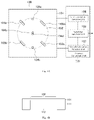
- FIG. 1A is a plan view illustrating a configuration of a pressure measurement device according to Embodiment 1 of the present disclosure.
- FIG. 1B is a sectional view illustrating a configuration of the pressure measurement device according to Embodiment 1 of the present disclosure.
- FIG. 2A is a plan view illustrating a configuration of a pressure measurement device according to Embodiment 2 of the present disclosure.
- FIG. 2B is a sectional view illustrating a configuration of the pressure measurement device according to Embodiment 2 of the present disclosure.
- FIG. 3 is a plan view illustrating a partial configuration of another pressure measurement device according to Embodiment 3 of the present disclosure.
- FIG. 4 is a configuration diagram illustrating a hardware configuration of the pressure measurement device according to the embodiment of the present disclosure.
- Embodiment 1 of the present disclosure First, a pressure measurement device according to Embodiment 1 of the present disclosure will be described with reference to FIGS. 1A and 1B .
- the pressure measurement device includes a pressure sensor 100 and a pressure calculation unit 105 .
- the pressure sensor 100 includes a diaphragm layer 101 and a pressure receiving region 102 formed in the diaphragm layer 101 .
- the pressure receiving region 102 has a circular shape in a plan view.
- the pressure receiving region 102 is a partial region of the diaphragm layer 101 , and for example, the pressure receiving region 102 can be deflected (deformed) in a normal direction of a plane of the diaphragm layer 101 .
- the pressure receiving region 102 may have a polygonal shape such as a square shape in a plan view.
- the diaphragm layer 101 is formed on a base 111 .
- the base 111 has a through-hole 112 that penetrates the base 111 in a thickness direction.
- the base 111 can be formed of single-crystal silicon.
- the pressure receiving region 102 is a partial region of the diaphragm layer 101 which is defined by a space of the through-hole 112 .
- the pressure sensor 100 includes a first piezostrictive element 103 a , a second piezostrictive element 103 b , a third piezostrictive element 103 c , and a fourth piezostrictive element 103 d in the diaphragm layer 101 in an outer peripheral portion of the pressure receiving region 102 .
- Each of the first piezostrictive element 103 a , the second piezostrictive element 103 b , the third piezostrictive element 103 c , and the fourth piezostrictive element 103 d serves as a piezostrictive measurement unit that measures a strain of the pressure receiving region 102 by using a piezoresistive effect.
- the piezostrictive element can be disposed at a position where generated stress peaks in the pressure receiving region 102 .
- the piezostrictive element is disposed at a location where the piezoelectric effect is generated in the pressure receiving region 102 .
- the diaphragm layer 101 is formed of single-crystal silicon whose main surface has a plane orientation ( 100 ).
- the piezostrictive element can be formed of a piezoresistance region including a p-type region into which boron (B) serving as a p-type impurity is introduced, at a predetermined location of the diaphragm layer 101 formed of the single-crystal silicon.
- first piezostrictive element 103 a four of the first piezostrictive element 103 a , the second piezostrictive element 103 b , the third piezostrictive element 103 c , and the fourth piezostrictive element 103 d are disposed at an equal interval in a circumferential direction of the pressure receiving region 102 .
- a first straight line connecting the first piezostrictive element 103 a and the third piezostrictive element 103 c and a second straight line connecting the second piezostrictive element 103 b and the fourth piezostrictive element 103 d are orthogonal to each other.
- the first straight line and the second straight line extend in a crystalline orientation 110 of the single-crystal silicon whose main surface forming the diaphragm layer 101 has a plane orientation ( 100 ).
- the first piezostrictive element 103 a and the third piezostrictive element 103 c are formed in a rectangular shape in which a longitudinal direction extends in the crystalline orientation 110 of the single-crystal silicon, and measure a strain generated by deflection of the pressure receiving region 102 .
- the first piezostrictive element 103 a and the third piezostrictive element 103 c are formed in a rectangular shape in which each axis in the longitudinal direction is parallel to a straight line extending in a radial direction from a center of the pressure receiving region 102 .
- the second piezostrictive element 103 b and the fourth piezostrictive element 103 d are formed in a rectangular shape in which the longitudinal direction extends in the crystalline orientation 110 of the single-crystal silicon, and measure the strain generated by the deflection of the pressure receiving region 102 .
- the second piezostrictive element 103 b and the fourth piezostrictive element 103 d are formed in a rectangular shape in which each axis in the longitudinal direction is perpendicular to the straight line extending in the radial direction from the center of the pressure receiving region 102 .
- the first piezostrictive element 103 a and the third piezostrictive element 103 c , and the second piezostrictive element 103 b and the fourth piezostrictive element 103 d are in a state where signs of respective resistance values are different from each other.
- the pressure sensor 100 includes a first magnetostrictive element 104 a , a second magnetostrictive element 104 b , a third magnetostrictive element 104 c , and a fourth magnetostrictive element 104 d in the pressure receiving region 102 of the diaphragm layer 101 .
- the first magnetostrictive element 104 a , the second magnetostrictive element 104 b , the third magnetostrictive element 104 c , and the fourth magnetostrictive element 104 d are formed of a material whose magnetization is changed due to the strain, and serve as a magnetostrictive measurement unit that measures the strain of the pressure receiving region 102 .
- the magnetostrictive element can be disposed at a position where the generated stress peaks in the pressure receiving region 102 .
- the magnetostrictive element includes a detection magnetic layer whose magnetization is changed due to the strain and a reference magnetic layer serving as a reference for the detection magnetic layer.
- the detection magnetic layer and the reference magnetic layer are subjected to tunnel junction via a barrier layer, and measure the strain of the pressure receiving region 102 by using a resistance change between the detection magnetic layer and the reference magnetic layer.
- the reference magnetic layer is a layer having fixed magnetization, and the magnetization is not changed due to the strain.
- the detection magnetic layer, the barrier layer, and the reference magnetic layer of each magnetostrictive element are disposed on the diaphragm layer 101 in a state of being stacked in a thickness direction of the diaphragm layer 101 .
- the first magnetostrictive element 104 a and the second magnetostrictive element 104 b are disposed at locations where a tensile strain is generated due to the deflection of the pressure receiving region 102 .
- the first magnetostrictive element 104 a and the second magnetostrictive element 104 b are disposed in the diaphragm layer 101 on an outer peripheral portion of the pressure receiving region 102 . High sensitivity can be obtained by disposing the elements at the location where the tensile strain is most generated (position where the tensile strain peaks).
- the third magnetostrictive element 104 c and the fourth magnetostrictive element 104 d are disposed at locations where a compression strain is generated due to the deflection of the pressure receiving region 102 .
- the third magnetostrictive element 104 c and the fourth magnetostrictive element 104 d are disposed in a central portion of the pressure receiving region 102 .
- the third magnetostrictive element 104 c and the fourth magnetostrictive element 104 d can also be disposed at locations where the strain is not generated (outside the pressure receiving region 102 ).
- first magnetostrictive element 104 a , the second magnetostrictive element 104 b , the third magnetostrictive element 104 c , and the fourth magnetostrictive element 104 d are disposed at locations different from those of the first piezostrictive element 103 a , the second piezostrictive element 103 b , the third piezostrictive element 103 c , and the fourth piezostrictive element 103 d .
- an angle formed between a third straight line connecting the first magnetostrictive element 104 a and the third magnetostrictive element 104 c and the first straight line can be set to 45°.
- the first piezostrictive element 103 a , the second piezostrictive element 103 b , the third piezostrictive element 103 c , and the fourth piezostrictive element 103 d form a first bridge circuit using the elements as resistance elements.
- the first bridge circuit outputs a change in the resistance value of each piezostrictive element (piezoresistance region) which is caused by the generated stress, as a voltage change.
- Each node of the first bridge circuit is connected to an electrode (not illustrated) via a wiring pattern formed on a surface of a region (not illustrated) of the diaphragm layer 101 .
- the first magnetostrictive element 104 a , the second magnetostrictive element 104 b , the third magnetostrictive element 104 c , and the fourth magnetostrictive element 104 d form a second bridge circuit using the elements as resistance elements.
- the second bridge circuit outputs a change in the resistance value of each magnetic tunnel junction element which is caused by the generated stress, as a voltage change.
- the magnetostrictive element In the magnetostrictive element, a detection magnetic layer whose magnetization is changed due to the strain, a non-magnetic layer formed of a non-magnetic material, and a reference magnetic layer serving as a reference for the detection magnetic layer are stacked in this order.
- the magnetostrictive element can measure the strain of the pressure receiving region 102 by using a resistance change in a direction parallel to a plane of the non-magnetic layer. In this case, as in the configuration of the piezostrictive element, four of the first magnetostrictive element, the second magnetostrictive element, the third magnetostrictive element, and the fourth magnetostrictive element can be used.
- the shape of the first magnetostrictive element and the third magnetostrictive element in a plan view can be a rectangular shape in which each axis in the longitudinal direction is parallel to the straight line extending in the radial direction from the center of the pressure receiving region 102 .
- the shape of the second magnetostrictive element and the fourth magnetostrictive element in a plan view can be a rectangular shape in which each axis in the longitudinal direction is perpendicular to the straight line extending in the radial direction from the center of the pressure receiving region 102 .
- the pressure calculation unit 105 includes a first calculation function unit 106 , a second calculation function unit 107 , and a switching function unit 108 .
- the first calculation function unit 106 calculates a pressure value received by the pressure receiving region 102 , based on a measurement result of the above-described piezostrictive measurement unit.
- the second calculation function unit 107 calculates a pressure value received by the pressure receiving region 102 , based on a measurement result of the magnetostrictive measurement unit.
- the switching function unit 108 outputs the pressure value calculated by the second calculation function unit 107 until the pressure value calculated by the first calculation function unit 106 exceeds a set threshold value, and outputs the pressure value calculated by the first calculation function unit 106 when the pressure value calculated by the first calculation function unit 106 exceeds the threshold value.
- the threshold value is determined, based on a range in which the magnetostrictive measurement unit (magnetostrictive element) has response linearity.
- the pressure value calculated by the piezostrictive measurement unit in a range where the pressure value calculated by the piezostrictive measurement unit is smaller than the set threshold value, the pressure value calculated by the magnetostrictive measurement unit is selected (output). In a range where the pressure value calculated by the piezostrictive measurement unit is greater than the set threshold value, the pressure value calculated by the piezostrictive measurement unit is selected (output). Accordingly, the pressure can be measured with satisfactory sensitivity in a low-pressure range, and can be accurately measured in a wider pressure range.
- the pressure measurement device includes a pressure sensor 100 a and a pressure calculation unit 105 a .
- the pressure sensor 100 a includes the diaphragm layer 101 and the pressure receiving region 102 formed in the diaphragm layer 101 .
- the pressure sensor 100 a includes the first piezostrictive element 103 a , the second piezostrictive element 103 b , the third piezostrictive element 103 c , and the fourth piezostrictive element 103 d .
- the pressure measurement device includes the first magnetostrictive element 104 a , the second magnetostrictive element 104 b , the third magnetostrictive element 104 c , and the fourth magnetostrictive element 104 d .
- the configurations are the same as those in Embodiment 1 described above.
- a first auxiliary pressure receiving region 202 a a first auxiliary pressure receiving region 202 a , a second auxiliary pressure receiving region 202 b , a third auxiliary pressure receiving region 202 c , and a fourth auxiliary pressure receiving region 202 d are formed around the pressure receiving region 102 of the diaphragm layer 101 .
- the second auxiliary pressure receiving region 202 b and the fourth auxiliary pressure receiving region 202 d are partial regions of the diaphragm layer 101 which are defined by a cavity 113 b and a cavity 113 d which are formed in the base 111 .
- FIG. 2B illustrates a cross section taken along a line passing through the central portion of the pressure receiving region 102 c in FIG. 2A .
- Each of the first auxiliary pressure receiving region 202 a , the second auxiliary pressure receiving region 202 b , the third auxiliary pressure receiving region 202 c , and the fourth auxiliary pressure receiving region 202 d has a rectangular shape having different lengths of adjacent sides in a plan view.
- a first auxiliary piezostrictive element 203 a and a second auxiliary piezostrictive element 203 b are provided in the first auxiliary pressure receiving region 202 a .
- a first auxiliary magnetostrictive element 204 a and a second auxiliary magnetostrictive element 204 b are provided in the second auxiliary pressure receiving region 202 b .
- a third auxiliary piezostrictive element 203 c and a fourth auxiliary piezostrictive element 203 d are provided in the third auxiliary pressure receiving region 202 c .
- a third auxiliary magnetostrictive element 204 c and a fourth auxiliary magnetostrictive element 204 d are provided in the fourth auxiliary pressure receiving region 202 d.
- the first auxiliary piezostrictive element 203 a , the second auxiliary piezostrictive element 203 b , the third auxiliary piezostrictive element 203 c , and the fourth auxiliary piezostrictive element 203 d are the same as the first piezostrictive element 103 a , the second piezostrictive element 103 b , the third piezostrictive element 103 c , and the fourth piezostrictive element 103 d , and are elements including the piezoresistance region.
- the first auxiliary magnetostrictive element 204 a , the second auxiliary magnetostrictive element 204 b , the third auxiliary magnetostrictive element 204 c , and the fourth auxiliary magnetostrictive element 204 d are the same as the first magnetostrictive element 104 a , the second magnetostrictive element 104 b , the third magnetostrictive element 104 c , and the fourth magnetostrictive element 104 d.
- a differential pressure measurement unit is configured to include the pressure receiving region 102 .
- a first static pressure measurement unit is configured to include the first auxiliary pressure receiving region 202 a and the third auxiliary pressure receiving region 202 c .
- a second static pressure measurement unit is configured to include the second auxiliary pressure receiving region 202 b and the fourth auxiliary pressure receiving region 202 d (refer to PTL 1).
- each of the first auxiliary piezostrictive element 203 a , the first auxiliary magnetostrictive element 204 a , the third auxiliary piezostrictive element 203 c , and the third auxiliary magnetostrictive element 204 c is disposed in the center of each of the first auxiliary pressure receiving region 202 a , the second auxiliary pressure receiving region 202 b , the third auxiliary pressure receiving region 202 c , and the fourth auxiliary pressure receiving region 202 d , respectively.
- first auxiliary piezostrictive element 203 a and the third auxiliary piezostrictive element 203 c are provided along the longitudinal direction of the first auxiliary pressure receiving region 202 a and the third auxiliary pressure receiving region 202 c having a rectangular shape in a plan view, respectively.
- each of the second auxiliary piezostrictive element 203 b , the second auxiliary magnetostrictive element 204 b , the fourth auxiliary piezostrictive element 203 d , and the fourth auxiliary magnetostrictive element 204 d is disposed on an edge of each of the first auxiliary pressure receiving region 202 a , the second auxiliary pressure receiving region 202 b , the third auxiliary pressure receiving region 202 c , and the fourth auxiliary pressure receiving region 202 d .
- the second auxiliary piezostrictive element 203 b and the fourth auxiliary piezostrictive element 203 d are provided along the longitudinal direction of the first auxiliary pressure receiving region 202 a and the third auxiliary pressure receiving region 202 c having a rectangular shape in a plan view, respectively.
- the pressure calculation unit 105 a includes the first calculation function unit 106 , the second calculation function unit 107 , a switching function unit 108 a , a first correction function unit 109 , and a second correction function unit 110 .
- the first calculation function unit 106 and the second calculation function unit 107 are the same as those in Embodiment 1 described above.
- the first correction function unit 109 corrects a pressure value calculated by the first calculation function unit 106 , based on a measurement result of the first static pressure measurement unit configured to include the first auxiliary pressure receiving region 202 a and the third auxiliary pressure receiving region 202 c .
- the second correction function unit 110 corrects a pressure value calculated by the second calculation function unit 107 , based on a measurement result of the second static pressure measurement unit configured to include the second auxiliary pressure receiving region 202 b and the fourth auxiliary pressure receiving region 202 d.
- the switching function unit 108 a first outputs a pressure value corrected by the second correction function unit 110 until a pressure value corrected by the first correction function unit 109 exceeds a set threshold value.
- the switching function unit 108 a outputs the pressure value corrected by the first correction function unit 109 .
- the stress generated in the static pressure measurement unit can be efficiently measured.
- measurement sensitivity of a static pressure can be improved.
- the pressure value calculated by the calculation unit is corrected by the static pressure correction function unit. Accordingly, it is possible to prevent a problem called a crosstalk in which a zero point of an output is shifted due to the static pressure affecting the differential pressure and the pressure.
- the pressure is measured by the magnetostrictive measurement unit in a range having a small pressure value, and the pressure is measured by the piezostrictive measurement unit in a range having a great pressure value. Therefore, the pressure can be measured with satisfactory sensitivity in a low-pressure range, and can be accurately measured in a wider pressure range.
- the pressure receiving region can have a square shape in a plan view.
- a pressure sensor 100 b using a pressure receiving region 102 a formed in a square shape in a plan view will be described with reference to FIG. 3 .
- the pressure sensor 100 b includes the diaphragm layer 101 and the pressure receiving region 102 a formed in the diaphragm layer 101 .
- the pressure receiving region 102 a has a square shape in a plan view. Each side of the square shape extends in the crystalline orientation 110 of the single-crystal silicon whose main surface forming the diaphragm layer 101 has a plane orientation ( 100 ).
- the pressure sensor 100 b includes a first piezostrictive element 123 a , a second piezostrictive element 123 b , a third piezostrictive element 123 c , and a fourth piezostrictive element 123 d .
- a set of the first piezostrictive element 123 a and the second piezostrictive element 123 b is disposed in a central portion of a first side 161 of the pressure receiving region 102 a having a square shape in a plan view.
- a set of the third piezostrictive element 123 c and the fourth piezostrictive element 123 d is disposed in a central portion of a second side 162 of the pressure receiving region 102 a having a square shape in a plan view.
- the second side 162 is a side adjacent to the first side 161 .
- the pressure sensor 100 b includes a first magnetostrictive element 124 a , a second magnetostrictive element 124 b , a third magnetostrictive element 124 c , and a fourth magnetostrictive element 124 d .
- the first magnetostrictive element 124 a is disposed in a central portion of a fourth side 164 of the pressure receiving region 102 a having a square shape in a plan view.
- the second magnetostrictive element 124 b is disposed in a central portion of a third side 163 of the pressure receiving region 102 a having a square shape in a plan view.
- the third side 163 is a side adjacent to the second side 162 and the fourth side 164 and facing the first side 161 .
- the fourth side 164 is a side adjacent to the first side 161 and the third side 163 and facing the second side 162 .
- the first auxiliary pressure receiving region 202 a , the second auxiliary pressure receiving region 202 b , the third auxiliary pressure receiving region 202 c , and the fourth auxiliary pressure receiving region 202 d are formed around the pressure receiving region 102 a of the diaphragm layer 101 .
- the first auxiliary pressure receiving region 202 a and the fourth auxiliary pressure receiving region 202 d are disposed on a first straight line 151 passing through a midpoint of the first side 161 and a midpoint of the third side 163 .
- the second auxiliary pressure receiving region 202 b and the third auxiliary pressure receiving region 202 c are disposed on a second straight line 152 passing through a midpoint of the second side 162 and a midpoint of the fourth side 164 .
- a set of the first piezostrictive element 123 a and the second piezostrictive element 123 b is disposed on the first straight line 151 .
- the first auxiliary pressure receiving region 202 a is disposed on an extension line in which a set of the first piezostrictive element 123 a and the second piezostrictive element 123 b is disposed when viewed from a center of the pressure receiving region 102 a .
- the second magnetostrictive element 124 b is disposed on the first straight line 151 .
- the fourth auxiliary pressure receiving region 202 d is disposed on an extension line in which the second magnetostrictive element 124 b is disposed when viewed from the center of the pressure receiving region 102 a.
- the first magnetostrictive element 124 a is disposed on the second straight line 152 .
- the second auxiliary pressure receiving region 202 b is disposed on an extension line in which the first magnetostrictive element 124 a is disposed when viewed from the center of the pressure receiving region 102 a .
- a set of the third piezostrictive element 123 c and the fourth piezostrictive element 123 d is disposed on the second straight line 152 .
- the third auxiliary pressure receiving region 202 c is disposed on an extension line in which a set of the third piezostrictive element 123 c and the fourth piezostrictive element 123 d is disposed when viewed from the center of the pressure receiving region 102 a.
- the first auxiliary piezostrictive element 203 a and the second auxiliary piezostrictive element 203 b are provided in the first auxiliary pressure receiving region 202 a .
- the first auxiliary magnetostrictive element 204 a and the second auxiliary magnetostrictive element 204 b are provided in the second auxiliary pressure receiving region 202 b .
- the third auxiliary piezostrictive element 203 c and the fourth auxiliary piezostrictive element 203 d are provided in the third auxiliary pressure receiving region 202 c .
- the third auxiliary magnetostrictive element 204 c and the fourth auxiliary magnetostrictive element 204 d are provided in the fourth auxiliary pressure receiving region 202 d.
- the first auxiliary piezostrictive element 203 a , the second auxiliary piezostrictive element 203 b , the third auxiliary piezostrictive element 203 c , and the fourth auxiliary piezostrictive element 203 d are the same as the first piezostrictive element 123 a , the second piezostrictive element 123 b , the third piezostrictive element 123 c , and the fourth piezostrictive element 123 d , and are elements including the piezoresistance region.
- the first auxiliary magnetostrictive element 204 a , the second auxiliary magnetostrictive element 204 b , the third auxiliary magnetostrictive element 204 c , and the fourth auxiliary magnetostrictive element 204 d are the same as the first magnetostrictive element 124 a , the second magnetostrictive element 124 b , the third magnetostrictive element 124 c , and the fourth magnetostrictive element 124 d.
- the differential pressure measurement unit is configured to include the pressure receiving region 102 a
- the static pressure measurement unit is configured to include the first auxiliary pressure receiving region 202 a , the second auxiliary pressure receiving region 202 b , the third auxiliary pressure receiving region 202 c , and the fourth auxiliary pressure receiving region 202 d (refer to PTL 1).
- each of the first auxiliary piezostrictive element 203 a , the first auxiliary magnetostrictive element 204 a , the third auxiliary piezostrictive element 203 c , and the third auxiliary magnetostrictive element 204 c is disposed in the center of each of the first auxiliary pressure receiving region 202 a , the second auxiliary pressure receiving region 202 b , the third auxiliary pressure receiving region 202 c , and the fourth auxiliary pressure receiving region 202 d .
- the first auxiliary piezostrictive element 203 a and the third auxiliary piezostrictive element 203 c are provided along the longitudinal direction of the auxiliary pressure receiving region having a rectangular shape in a plan view.
- each of the second auxiliary piezostrictive element 203 b , the second auxiliary magnetostrictive element 204 b , the fourth auxiliary piezostrictive element 203 d , and the fourth auxiliary magnetostrictive element 204 d is disposed on an edge of each of the first auxiliary pressure receiving region 202 a , the second auxiliary pressure receiving region 202 b , the third auxiliary pressure receiving region 202 c , and the fourth auxiliary pressure receiving region 202 d .
- the second auxiliary piezostrictive element 203 b and the fourth auxiliary piezostrictive element 203 d are provided along the longitudinal direction of the auxiliary pressure receiving region having a rectangular shape in a plan view.
- the pressure sensor 100 b can also efficiently measure the stress generated in the static pressure measurement unit. As a result, measurement sensitivity of a static pressure can be improved.
- the pressure calculation unit of the pressure measurement device functions as a computer device including a central processing unit (CPU) 301 , a main storage device 302 , an external storage device 303 , and a network connection device 304 .
- a program deployed in the main storage device 302 operates the CPU 301 (program is executed).
- the above-described program is a program for causing the computer to execute the functions of the pressure calculation unit in the above-described embodiment.
- the network connection device 304 is connected to a network 305 .
- each of the functions can be distributed to a plurality of computer devices.
- the above-described pressure calculation unit can also be configured to include a programmable logic device (PLD) such as a field-programmable gate array (FPGA).
- PLD programmable logic device
- FPGA field-programmable gate array
- a logic element of the FPGA is provided with the storage unit, the first calculation function unit, the second calculation function unit, the switching function unit, the first correction function unit, and the second correction function unit.
- the logic element can function as the pressure calculation unit.
- Each of the storage circuit, the first calculation circuit, the second calculation circuit, the switching circuit, the first correction circuit, and the second correction circuit can be written on the FPGA by connecting a predetermined writing device.
- each of the above-described circuits written on the FPGA can be confirmed by the writing device connected to the FPGA.
- the piezostrictive measurement unit and the magnetostrictive measurement unit are provided in the pressure receiving region of the diaphragm layer. Therefore, the pressure can be accurately measured in a wider pressure range.
- 100 pressure sensor, 101 : diaphragm layer, 102 : pressure receiving region, 103 a : first piezostrictive element, 103 b : second piezostrictive element, 103 c : third piezostrictive element, 103 d : fourth piezostrictive element, 104 a : first magnetostrictive element, 104 b : second magnetostrictive element, 104 c : third magnetostrictive element, 104 d : fourth magnetostrictive element, 105 : pressure calculation unit, 106 : first calculation function unit, 107 : second calculation function unit, 108 : switching function unit, 111 : base, 112 : through-hole
Landscapes
- Physics & Mathematics (AREA)
- General Physics & Mathematics (AREA)
- Chemical & Material Sciences (AREA)
- Analytical Chemistry (AREA)
- Measuring Fluid Pressure (AREA)
- Pressure Sensors (AREA)
Abstract
Description
Claims (15)
Applications Claiming Priority (3)
| Application Number | Priority Date | Filing Date | Title |
|---|---|---|---|
| JP2020013755A JP7396913B2 (en) | 2020-01-30 | 2020-01-30 | pressure measuring device |
| JPJP2020-013755 | 2020-01-30 | ||
| JP2020-013755 | 2020-01-30 |
Publications (2)
| Publication Number | Publication Date |
|---|---|
| US20210239554A1 US20210239554A1 (en) | 2021-08-05 |
| US11480485B2 true US11480485B2 (en) | 2022-10-25 |
Family
ID=77025258
Family Applications (1)
| Application Number | Title | Priority Date | Filing Date |
|---|---|---|---|
| US17/158,201 Active 2041-03-14 US11480485B2 (en) | 2020-01-30 | 2021-01-26 | Pressure measurement device having piezostrictive and magnetostrictive measurement units |
Country Status (3)
| Country | Link |
|---|---|
| US (1) | US11480485B2 (en) |
| JP (1) | JP7396913B2 (en) |
| CN (1) | CN113203515B (en) |
Families Citing this family (2)
| Publication number | Priority date | Publication date | Assignee | Title |
|---|---|---|---|---|
| DE102020121968A1 (en) | 2020-08-21 | 2022-02-24 | Gemü Gebr. Müller Apparatebau Gmbh & Co. Kommanditgesellschaft | Sensor location, diaphragm valve and procedure |
| JP2023117602A (en) * | 2022-02-14 | 2023-08-24 | アズビル株式会社 | hydrogen sensor |
Citations (5)
| Publication number | Priority date | Publication date | Assignee | Title |
|---|---|---|---|---|
| WO2006002988A1 (en) * | 2004-07-05 | 2006-01-12 | Infineon Technologies Ag | Sensor and method for producing said sensor |
| US20100083765A1 (en) | 2008-10-07 | 2010-04-08 | Yamatake Corporation | Pressure sensor |
| JP2016014581A (en) | 2014-07-02 | 2016-01-28 | 株式会社東芝 | Pressure sensor, and microphone, blood pressure sensor, and touch panel using pressure sensor |
| US9534972B2 (en) * | 2012-02-16 | 2017-01-03 | 7-Sigma Inc. | Pressure sensor with a deformable electrically resistive membrane |
| US10962433B2 (en) * | 2017-03-03 | 2021-03-30 | Trafag Ag | Pressure sensor and pressure measuring method |
Family Cites Families (13)
| Publication number | Priority date | Publication date | Assignee | Title |
|---|---|---|---|---|
| JPH04303724A (en) * | 1991-03-29 | 1992-10-27 | Shimadzu Corp | air pressure measuring device |
| US6694822B1 (en) * | 1999-07-20 | 2004-02-24 | Fidelica Microsystems, Inc. | Use of multi-layer thin films as stress sensor |
| JP5156671B2 (en) * | 2009-02-27 | 2013-03-06 | 株式会社日立製作所 | Magnetic field detection device and measurement device |
| EP2458359B1 (en) * | 2009-07-24 | 2022-04-27 | Rohm Co., Ltd. | Semiconductor pressure sensor, pressure sensor device, electronic apparatus, and method for manufacturing semiconductor pressure sensor |
| JP5443421B2 (en) * | 2011-03-24 | 2014-03-19 | 株式会社東芝 | Magnetoresistive element, magnetic head gimbal assembly, and magnetic recording / reproducing apparatus |
| EP2662675A1 (en) * | 2012-05-07 | 2013-11-13 | Melexis Technologies NV | Method for determining a stress value for isotropic stress and method for determining a magnetic field and stress sensor and Hall effect sensor |
| JP6055286B2 (en) * | 2012-11-20 | 2016-12-27 | 株式会社東芝 | Pressure sensor, microphone, blood pressure sensor, and touch panel |
| JP6113581B2 (en) * | 2013-06-12 | 2017-04-12 | 株式会社東芝 | Pressure sensor, acoustic microphone, blood pressure sensor, and touch panel |
| JP6275549B2 (en) * | 2014-05-26 | 2018-02-07 | 株式会社東芝 | Pressure sensor, microphone, ultrasonic sensor, blood pressure sensor, and touch panel |
| KR20160088111A (en) * | 2015-01-15 | 2016-07-25 | 삼성전기주식회사 | Complex sensor, package having the same and manufacturing method thereof |
| JP6421101B2 (en) * | 2015-09-09 | 2018-11-07 | 株式会社東芝 | Sensor, information terminal, microphone, blood pressure sensor, and touch panel |
| JP6595422B2 (en) * | 2016-08-24 | 2019-10-23 | 株式会社東芝 | Sensor and electronic equipment |
| JP6462078B2 (en) * | 2017-09-12 | 2019-01-30 | 株式会社東芝 | Pressure sensor, microphone and sound processing system |
-
2020
- 2020-01-30 JP JP2020013755A patent/JP7396913B2/en active Active
-
2021
- 2021-01-26 US US17/158,201 patent/US11480485B2/en active Active
- 2021-01-28 CN CN202110117041.9A patent/CN113203515B/en active Active
Patent Citations (7)
| Publication number | Priority date | Publication date | Assignee | Title |
|---|---|---|---|---|
| WO2006002988A1 (en) * | 2004-07-05 | 2006-01-12 | Infineon Technologies Ag | Sensor and method for producing said sensor |
| US20100083765A1 (en) | 2008-10-07 | 2010-04-08 | Yamatake Corporation | Pressure sensor |
| JP5227729B2 (en) | 2008-10-07 | 2013-07-03 | アズビル株式会社 | Pressure sensor |
| US9534972B2 (en) * | 2012-02-16 | 2017-01-03 | 7-Sigma Inc. | Pressure sensor with a deformable electrically resistive membrane |
| JP2016014581A (en) | 2014-07-02 | 2016-01-28 | 株式会社東芝 | Pressure sensor, and microphone, blood pressure sensor, and touch panel using pressure sensor |
| US20180356308A1 (en) | 2014-07-02 | 2018-12-13 | Kabushiki Kaisha Toshiba | Pressure sensor |
| US10962433B2 (en) * | 2017-03-03 | 2021-03-30 | Trafag Ag | Pressure sensor and pressure measuring method |
Also Published As
| Publication number | Publication date |
|---|---|
| JP7396913B2 (en) | 2023-12-12 |
| CN113203515B (en) | 2022-11-08 |
| JP2021120635A (en) | 2021-08-19 |
| US20210239554A1 (en) | 2021-08-05 |
| CN113203515A (en) | 2021-08-03 |
Similar Documents
| Publication | Publication Date | Title |
|---|---|---|
| US9513182B2 (en) | Pressure sensor having multiple piezoresistive elements | |
| US10317297B2 (en) | Semiconductor pressure sensor | |
| KR102313908B1 (en) | Method of manufacturing a pressure sensor | |
| JP2017500545A (en) | Semiconductor pressure sensor | |
| US11480485B2 (en) | Pressure measurement device having piezostrictive and magnetostrictive measurement units | |
| CN102288354B (en) | Piezo-resistive pressure sensor | |
| JP2021183986A (en) | Multi-axis tactile sensor | |
| US20250180423A1 (en) | Piezoresistive sensor element and piezoresistive pressure sensor with minimized long-term drift | |
| JP2012122924A (en) | Pressure sensor | |
| US11609139B2 (en) | Pressure sensor | |
| CN113252216A (en) | MEMS pressure sensor and manufacturing method thereof | |
| US10527513B2 (en) | Pressure sensor with resin portion and membrane having reduced temperature change distortion | |
| JP2895262B2 (en) | Composite sensor | |
| US20190204171A1 (en) | Pressure sensor | |
| JP2020046177A (en) | Pressure sensor element and pressure sensor module provided with it | |
| US12436049B2 (en) | Sensor die with a diaphragm | |
| JP2016138844A (en) | Strain sensor | |
| JP3071932B2 (en) | Semiconductor pressure sensor | |
| Vaziri et al. | Comparison between the conventional and Hairpin piezoresistive pressure sensors, focused on the effects of process deviations on the performance and process yield | |
| US9903883B2 (en) | Angular acceleration sensor and acceleration sensor | |
| CN113348348B (en) | Pressure Sensor | |
| JP2016053508A (en) | Pressure sensor | |
| JP2016136107A (en) | Pressure sensor | |
| CN118603374A (en) | Piezoresistive pressure sensor and electronic equipment | |
| JP2015114232A (en) | Semiconductor pressure sensor |
Legal Events
| Date | Code | Title | Description |
|---|---|---|---|
| AS | Assignment |
Owner name: AZBIL CORPORATION, JAPAN Free format text: ASSIGNMENT OF ASSIGNORS INTEREST;ASSIGNOR:TOKUDA, TOMOHISA;REEL/FRAME:055029/0485 Effective date: 20210120 |
|
| FEPP | Fee payment procedure |
Free format text: ENTITY STATUS SET TO UNDISCOUNTED (ORIGINAL EVENT CODE: BIG.); ENTITY STATUS OF PATENT OWNER: LARGE ENTITY |
|
| STPP | Information on status: patent application and granting procedure in general |
Free format text: DOCKETED NEW CASE - READY FOR EXAMINATION |
|
| STPP | Information on status: patent application and granting procedure in general |
Free format text: NON FINAL ACTION MAILED |
|
| STPP | Information on status: patent application and granting procedure in general |
Free format text: RESPONSE TO NON-FINAL OFFICE ACTION ENTERED AND FORWARDED TO EXAMINER |
|
| STPP | Information on status: patent application and granting procedure in general |
Free format text: NOTICE OF ALLOWANCE MAILED -- APPLICATION RECEIVED IN OFFICE OF PUBLICATIONS |
|
| STPP | Information on status: patent application and granting procedure in general |
Free format text: PUBLICATIONS -- ISSUE FEE PAYMENT VERIFIED |
|
| STCF | Information on status: patent grant |
Free format text: PATENTED CASE |
|
| MAFP | Maintenance fee payment |
Free format text: PAYMENT OF MAINTENANCE FEE, 4TH YEAR, LARGE ENTITY (ORIGINAL EVENT CODE: M1551); ENTITY STATUS OF PATENT OWNER: LARGE ENTITY Year of fee payment: 4 |