US11471678B2 - Cardiac cycle selection - Google Patents
Cardiac cycle selection Download PDFInfo
- Publication number
- US11471678B2 US11471678B2 US16/047,619 US201816047619A US11471678B2 US 11471678 B2 US11471678 B2 US 11471678B2 US 201816047619 A US201816047619 A US 201816047619A US 11471678 B2 US11471678 B2 US 11471678B2
- Authority
- US
- United States
- Prior art keywords
- cycle
- cardiac
- metric
- submetric
- cardiac cycles
- Prior art date
- Legal status (The legal status is an assumption and is not a legal conclusion. Google has not performed a legal analysis and makes no representation as to the accuracy of the status listed.)
- Active, expires
Links
Images


Classifications
-
- A—HUMAN NECESSITIES
- A61—MEDICAL OR VETERINARY SCIENCE; HYGIENE
- A61N—ELECTROTHERAPY; MAGNETOTHERAPY; RADIATION THERAPY; ULTRASOUND THERAPY
- A61N1/00—Electrotherapy; Circuits therefor
- A61N1/18—Applying electric currents by contact electrodes
- A61N1/32—Applying electric currents by contact electrodes alternating or intermittent currents
- A61N1/36—Applying electric currents by contact electrodes alternating or intermittent currents for stimulation
- A61N1/36014—External stimulators, e.g. with patch electrodes
- A61N1/3603—Control systems
-
- A—HUMAN NECESSITIES
- A61—MEDICAL OR VETERINARY SCIENCE; HYGIENE
- A61B—DIAGNOSIS; SURGERY; IDENTIFICATION
- A61B5/00—Measuring for diagnostic purposes; Identification of persons
- A61B5/24—Detecting, measuring or recording bioelectric or biomagnetic signals of the body or parts thereof
- A61B5/25—Bioelectric electrodes therefor
- A61B5/279—Bioelectric electrodes therefor specially adapted for particular uses
- A61B5/28—Bioelectric electrodes therefor specially adapted for particular uses for electrocardiography [ECG]
- A61B5/282—Holders for multiple electrodes
-
- A—HUMAN NECESSITIES
- A61—MEDICAL OR VETERINARY SCIENCE; HYGIENE
- A61B—DIAGNOSIS; SURGERY; IDENTIFICATION
- A61B5/00—Measuring for diagnostic purposes; Identification of persons
- A61B5/24—Detecting, measuring or recording bioelectric or biomagnetic signals of the body or parts thereof
- A61B5/25—Bioelectric electrodes therefor
- A61B5/279—Bioelectric electrodes therefor specially adapted for particular uses
- A61B5/28—Bioelectric electrodes therefor specially adapted for particular uses for electrocardiography [ECG]
- A61B5/283—Invasive
- A61B5/287—Holders for multiple electrodes, e.g. electrode catheters for electrophysiological study [EPS]
-
- A—HUMAN NECESSITIES
- A61—MEDICAL OR VETERINARY SCIENCE; HYGIENE
- A61B—DIAGNOSIS; SURGERY; IDENTIFICATION
- A61B5/00—Measuring for diagnostic purposes; Identification of persons
- A61B5/24—Detecting, measuring or recording bioelectric or biomagnetic signals of the body or parts thereof
- A61B5/316—Modalities, i.e. specific diagnostic methods
- A61B5/318—Heart-related electrical modalities, e.g. electrocardiography [ECG]
- A61B5/346—Analysis of electrocardiograms
- A61B5/349—Detecting specific parameters of the electrocardiograph cycle
- A61B5/352—Detecting R peaks, e.g. for synchronising diagnostic apparatus; Estimating R-R interval
-
- A—HUMAN NECESSITIES
- A61—MEDICAL OR VETERINARY SCIENCE; HYGIENE
- A61B—DIAGNOSIS; SURGERY; IDENTIFICATION
- A61B5/00—Measuring for diagnostic purposes; Identification of persons
- A61B5/24—Detecting, measuring or recording bioelectric or biomagnetic signals of the body or parts thereof
- A61B5/316—Modalities, i.e. specific diagnostic methods
- A61B5/318—Heart-related electrical modalities, e.g. electrocardiography [ECG]
- A61B5/346—Analysis of electrocardiograms
- A61B5/349—Detecting specific parameters of the electrocardiograph cycle
- A61B5/366—Detecting abnormal QRS complex, e.g. widening
-
- A—HUMAN NECESSITIES
- A61—MEDICAL OR VETERINARY SCIENCE; HYGIENE
- A61B—DIAGNOSIS; SURGERY; IDENTIFICATION
- A61B5/00—Measuring for diagnostic purposes; Identification of persons
- A61B5/48—Other medical applications
- A61B5/4836—Diagnosis combined with treatment in closed-loop systems or methods
-
- A—HUMAN NECESSITIES
- A61—MEDICAL OR VETERINARY SCIENCE; HYGIENE
- A61N—ELECTROTHERAPY; MAGNETOTHERAPY; RADIATION THERAPY; ULTRASOUND THERAPY
- A61N1/00—Electrotherapy; Circuits therefor
- A61N1/18—Applying electric currents by contact electrodes
- A61N1/32—Applying electric currents by contact electrodes alternating or intermittent currents
- A61N1/321—Electromedical belts
-
- A—HUMAN NECESSITIES
- A61—MEDICAL OR VETERINARY SCIENCE; HYGIENE
- A61N—ELECTROTHERAPY; MAGNETOTHERAPY; RADIATION THERAPY; ULTRASOUND THERAPY
- A61N1/00—Electrotherapy; Circuits therefor
- A61N1/18—Applying electric currents by contact electrodes
- A61N1/32—Applying electric currents by contact electrodes alternating or intermittent currents
- A61N1/36—Applying electric currents by contact electrodes alternating or intermittent currents for stimulation
- A61N1/362—Heart stimulators
- A61N1/3627—Heart stimulators for treating a mechanical deficiency of the heart, e.g. congestive heart failure or cardiomyopathy
-
- A—HUMAN NECESSITIES
- A61—MEDICAL OR VETERINARY SCIENCE; HYGIENE
- A61N—ELECTROTHERAPY; MAGNETOTHERAPY; RADIATION THERAPY; ULTRASOUND THERAPY
- A61N1/00—Electrotherapy; Circuits therefor
- A61N1/18—Applying electric currents by contact electrodes
- A61N1/32—Applying electric currents by contact electrodes alternating or intermittent currents
- A61N1/36—Applying electric currents by contact electrodes alternating or intermittent currents for stimulation
- A61N1/362—Heart stimulators
- A61N1/365—Heart stimulators controlled by a physiological parameter, e.g. heart potential
- A61N1/36507—Heart stimulators controlled by a physiological parameter, e.g. heart potential controlled by gradient or slope of the heart potential
-
- A—HUMAN NECESSITIES
- A61—MEDICAL OR VETERINARY SCIENCE; HYGIENE
- A61N—ELECTROTHERAPY; MAGNETOTHERAPY; RADIATION THERAPY; ULTRASOUND THERAPY
- A61N1/00—Electrotherapy; Circuits therefor
- A61N1/18—Applying electric currents by contact electrodes
- A61N1/32—Applying electric currents by contact electrodes alternating or intermittent currents
- A61N1/36—Applying electric currents by contact electrodes alternating or intermittent currents for stimulation
- A61N1/362—Heart stimulators
- A61N1/365—Heart stimulators controlled by a physiological parameter, e.g. heart potential
- A61N1/368—Heart stimulators controlled by a physiological parameter, e.g. heart potential comprising more than one electrode co-operating with different heart regions
- A61N1/3682—Heart stimulators controlled by a physiological parameter, e.g. heart potential comprising more than one electrode co-operating with different heart regions with a variable atrioventricular delay
-
- A—HUMAN NECESSITIES
- A61—MEDICAL OR VETERINARY SCIENCE; HYGIENE
- A61N—ELECTROTHERAPY; MAGNETOTHERAPY; RADIATION THERAPY; ULTRASOUND THERAPY
- A61N1/00—Electrotherapy; Circuits therefor
- A61N1/18—Applying electric currents by contact electrodes
- A61N1/32—Applying electric currents by contact electrodes alternating or intermittent currents
- A61N1/36—Applying electric currents by contact electrodes alternating or intermittent currents for stimulation
- A61N1/362—Heart stimulators
- A61N1/365—Heart stimulators controlled by a physiological parameter, e.g. heart potential
- A61N1/368—Heart stimulators controlled by a physiological parameter, e.g. heart potential comprising more than one electrode co-operating with different heart regions
- A61N1/3684—Heart stimulators controlled by a physiological parameter, e.g. heart potential comprising more than one electrode co-operating with different heart regions for stimulating the heart at multiple sites of the ventricle or the atrium
-
- A—HUMAN NECESSITIES
- A61—MEDICAL OR VETERINARY SCIENCE; HYGIENE
- A61B—DIAGNOSIS; SURGERY; IDENTIFICATION
- A61B5/00—Measuring for diagnostic purposes; Identification of persons
- A61B5/24—Detecting, measuring or recording bioelectric or biomagnetic signals of the body or parts thereof
- A61B5/25—Bioelectric electrodes therefor
-
- A—HUMAN NECESSITIES
- A61—MEDICAL OR VETERINARY SCIENCE; HYGIENE
- A61B—DIAGNOSIS; SURGERY; IDENTIFICATION
- A61B5/00—Measuring for diagnostic purposes; Identification of persons
- A61B5/24—Detecting, measuring or recording bioelectric or biomagnetic signals of the body or parts thereof
- A61B5/316—Modalities, i.e. specific diagnostic methods
- A61B5/318—Heart-related electrical modalities, e.g. electrocardiography [ECG]
- A61B5/346—Analysis of electrocardiograms
- A61B5/349—Detecting specific parameters of the electrocardiograph cycle
- A61B5/363—Detecting tachycardia or bradycardia
-
- A—HUMAN NECESSITIES
- A61—MEDICAL OR VETERINARY SCIENCE; HYGIENE
- A61B—DIAGNOSIS; SURGERY; IDENTIFICATION
- A61B5/00—Measuring for diagnostic purposes; Identification of persons
- A61B5/24—Detecting, measuring or recording bioelectric or biomagnetic signals of the body or parts thereof
- A61B5/316—Modalities, i.e. specific diagnostic methods
- A61B5/318—Heart-related electrical modalities, e.g. electrocardiography [ECG]
- A61B5/346—Analysis of electrocardiograms
- A61B5/349—Detecting specific parameters of the electrocardiograph cycle
- A61B5/364—Detecting abnormal ECG interval, e.g. extrasystoles, ectopic heartbeats
-
- A—HUMAN NECESSITIES
- A61—MEDICAL OR VETERINARY SCIENCE; HYGIENE
- A61B—DIAGNOSIS; SURGERY; IDENTIFICATION
- A61B5/00—Measuring for diagnostic purposes; Identification of persons
- A61B5/68—Arrangements of detecting, measuring or recording means, e.g. sensors, in relation to patient
- A61B5/6801—Arrangements of detecting, measuring or recording means, e.g. sensors, in relation to patient specially adapted to be attached to or worn on the body surface
- A61B5/6802—Sensor mounted on worn items
- A61B5/6804—Garments; Clothes
- A61B5/6805—Vests
-
- A—HUMAN NECESSITIES
- A61—MEDICAL OR VETERINARY SCIENCE; HYGIENE
- A61B—DIAGNOSIS; SURGERY; IDENTIFICATION
- A61B5/00—Measuring for diagnostic purposes; Identification of persons
- A61B5/68—Arrangements of detecting, measuring or recording means, e.g. sensors, in relation to patient
- A61B5/6801—Arrangements of detecting, measuring or recording means, e.g. sensors, in relation to patient specially adapted to be attached to or worn on the body surface
- A61B5/683—Means for maintaining contact with the body
- A61B5/6831—Straps, bands or harnesses
-
- A—HUMAN NECESSITIES
- A61—MEDICAL OR VETERINARY SCIENCE; HYGIENE
- A61B—DIAGNOSIS; SURGERY; IDENTIFICATION
- A61B5/00—Measuring for diagnostic purposes; Identification of persons
- A61B5/68—Arrangements of detecting, measuring or recording means, e.g. sensors, in relation to patient
- A61B5/6846—Arrangements of detecting, measuring or recording means, e.g. sensors, in relation to patient specially adapted to be brought in contact with an internal body part, i.e. invasive
- A61B5/6847—Arrangements of detecting, measuring or recording means, e.g. sensors, in relation to patient specially adapted to be brought in contact with an internal body part, i.e. invasive mounted on an invasive device
- A61B5/686—Permanently implanted devices, e.g. pacemakers, other stimulators, biochips
-
- A—HUMAN NECESSITIES
- A61—MEDICAL OR VETERINARY SCIENCE; HYGIENE
- A61B—DIAGNOSIS; SURGERY; IDENTIFICATION
- A61B5/00—Measuring for diagnostic purposes; Identification of persons
- A61B5/72—Signal processing specially adapted for physiological signals or for diagnostic purposes
- A61B5/7203—Signal processing specially adapted for physiological signals or for diagnostic purposes for noise prevention, reduction or removal
-
- A—HUMAN NECESSITIES
- A61—MEDICAL OR VETERINARY SCIENCE; HYGIENE
- A61B—DIAGNOSIS; SURGERY; IDENTIFICATION
- A61B5/00—Measuring for diagnostic purposes; Identification of persons
- A61B5/72—Signal processing specially adapted for physiological signals or for diagnostic purposes
- A61B5/7271—Specific aspects of physiological measurement analysis
- A61B5/7275—Determining trends in physiological measurement data; Predicting development of a medical condition based on physiological measurements, e.g. determining a risk factor
-
- A—HUMAN NECESSITIES
- A61—MEDICAL OR VETERINARY SCIENCE; HYGIENE
- A61N—ELECTROTHERAPY; MAGNETOTHERAPY; RADIATION THERAPY; ULTRASOUND THERAPY
- A61N1/00—Electrotherapy; Circuits therefor
- A61N1/18—Applying electric currents by contact electrodes
- A61N1/32—Applying electric currents by contact electrodes alternating or intermittent currents
- A61N1/36—Applying electric currents by contact electrodes alternating or intermittent currents for stimulation
- A61N1/362—Heart stimulators
- A61N1/3621—Heart stimulators for treating or preventing abnormally high heart rate
- A61N1/3622—Heart stimulators for treating or preventing abnormally high heart rate comprising two or more electrodes co-operating with different heart regions
-
- A—HUMAN NECESSITIES
- A61—MEDICAL OR VETERINARY SCIENCE; HYGIENE
- A61N—ELECTROTHERAPY; MAGNETOTHERAPY; RADIATION THERAPY; ULTRASOUND THERAPY
- A61N1/00—Electrotherapy; Circuits therefor
- A61N1/18—Applying electric currents by contact electrodes
- A61N1/32—Applying electric currents by contact electrodes alternating or intermittent currents
- A61N1/36—Applying electric currents by contact electrodes alternating or intermittent currents for stimulation
- A61N1/362—Heart stimulators
- A61N1/365—Heart stimulators controlled by a physiological parameter, e.g. heart potential
- A61N1/368—Heart stimulators controlled by a physiological parameter, e.g. heart potential comprising more than one electrode co-operating with different heart regions
- A61N1/3684—Heart stimulators controlled by a physiological parameter, e.g. heart potential comprising more than one electrode co-operating with different heart regions for stimulating the heart at multiple sites of the ventricle or the atrium
- A61N1/36843—Bi-ventricular stimulation
-
- A—HUMAN NECESSITIES
- A61—MEDICAL OR VETERINARY SCIENCE; HYGIENE
- A61N—ELECTROTHERAPY; MAGNETOTHERAPY; RADIATION THERAPY; ULTRASOUND THERAPY
- A61N1/00—Electrotherapy; Circuits therefor
- A61N1/18—Applying electric currents by contact electrodes
- A61N1/32—Applying electric currents by contact electrodes alternating or intermittent currents
- A61N1/36—Applying electric currents by contact electrodes alternating or intermittent currents for stimulation
- A61N1/362—Heart stimulators
- A61N1/365—Heart stimulators controlled by a physiological parameter, e.g. heart potential
- A61N1/368—Heart stimulators controlled by a physiological parameter, e.g. heart potential comprising more than one electrode co-operating with different heart regions
- A61N1/3686—Heart stimulators controlled by a physiological parameter, e.g. heart potential comprising more than one electrode co-operating with different heart regions configured for selecting the electrode configuration on a lead
-
- A—HUMAN NECESSITIES
- A61—MEDICAL OR VETERINARY SCIENCE; HYGIENE
- A61N—ELECTROTHERAPY; MAGNETOTHERAPY; RADIATION THERAPY; ULTRASOUND THERAPY
- A61N1/00—Electrotherapy; Circuits therefor
- A61N1/18—Applying electric currents by contact electrodes
- A61N1/32—Applying electric currents by contact electrodes alternating or intermittent currents
- A61N1/38—Applying electric currents by contact electrodes alternating or intermittent currents for producing shock effects
- A61N1/39—Heart defibrillators
- A61N1/3925—Monitoring; Protecting
Definitions
- the disclosure herein relates to systems and methods for use in the selection of a cardiac cycle, or heartbeat, from a plurality of cardiac cycles, e.g., for use in determining one or more features of the cardiac cycle.
- Implantable medical devices such as implantable pacemakers, cardioverters, defibrillators, or pacemaker-cardioverter-defibrillators, provide therapeutic electrical stimulation to the heart.
- IMDs may provide pacing to address bradycardia, or pacing or shocks in order to terminate tachyarrhythmia, such as tachycardia or fibrillation.
- the medical device may sense intrinsic depolarizations of the heart, detect arrhythmia based on the intrinsic depolarizations (or absence thereof), and control delivery of electrical stimulation to the heart if arrhythmia is detected based on the intrinsic depolarizations.
- IMDs may also provide cardiac resynchronization therapy (CRT), which is a form of pacing.
- CRT involves the delivery of pacing to the left ventricle, or both the left and right ventricles.
- the timing and location of the delivery of pacing pulses to the ventricle(s) may be selected to improve the coordination and efficiency of ventricular contraction.
- Systems for implanting medical devices may include workstations or other equipment in addition to the implantable medical device itself. In some cases, these other pieces of equipment assist the physician or other technician with placing the intracardiac leads at particular locations on the heart. In some cases, the equipment provides information to the physician about the electrical activity of the heart and the location of the intracardiac lead. The equipment may perform similar functions as the medical device, including delivering electrical stimulation to the heart and sensing the depolarizations of the heart. In some cases, the equipment may include equipment for obtaining an electrocardiogram (ECG) via electrodes on the surface, or skin, of the patient. More specifically, the patient may have a plurality of electrodes on an ECG belt or vest that surrounds the torso of the patient.
- ECG electrocardiogram
- a physician can perform a series of tests to evaluate a patient's cardiac response.
- the evaluation process can include detection of a baseline rhythm in which no electrical stimuli is delivered to cardiac tissue and another rhythm after electrical stimuli is delivered to the cardiac tissue.
- the ECG electrodes placed on the body surface of the patient may be used for various therapeutic purposes (e.g., cardiac resynchronization therapy) including optimizing lead location, pacing parameters, etc. based on one or more metrics derived from the signals captured by the ECG electrodes. For example, electrical heterogeneity information may be derived from electrical activation times computed from multiple electrodes on the body surface.
- the signals from multiple electrodes on the body surface can be used to determine one or more specific ECG features such as, e.g., QRS onset, peak, offset, etc. for a series of multiple heartbeats.
- ECG features may be used by themselves to evaluate cardiac health and/or therapy, or may be used to calculate, or compute, electrical activation times.
- QRS onset, peak, offset, etc. may be used by themselves to evaluate cardiac health and/or therapy, or may be used to calculate, or compute, electrical activation times.
- only a single QRS complex is used to determine the therapeutic nature of one or more parameters related to cardiac therapy such as, e.g., pacing parameters, lead location, etc.
- repeated measurements may have high computational and temporal costs in addition to unnecessary redundancy.
- the exemplary systems and methods described herein may create processes to identify irregular patterns within a QRS onset and QRS offset (e.g., premature ventricular contractions (PVCs), etc.) of a cardiac cycle and to determine which cardiac cycle, or heartbeat, is representative of the conduction pattern with the current pacing parameters.
- This cardiac cycle may then be identified and selected for further, more computationally-expensive metrics calculations for cardiac resynchronization therapy (CRT) optimization such as, e.g., generation of activation times, generation of electrical heterogeneity metrics, etc.
- CRT cardiac resynchronization therapy
- the exemplary systems and methods described herein may be configured to assist a user (e.g., a physician) in evaluating a patient without cardiac therapy being delivered to the patient (e.g., prior to IMD implant) and/or configuring cardiac therapy being delivered to a patient (e.g., cardiac therapy being performed on a patient during and/or after implantation of cardiac therapy apparatus).
- the systems and methods may be described as being noninvasive.
- the systems and methods may not need implantable devices such as leads, probes, sensors, catheters, etc. to evaluate and configure the cardiac therapy.
- the systems and methods may use electrical measurements taken noninvasively using, e.g., a plurality of external electrodes attached to the surface, or skin, of a patient about the patient's torso.
- One exemplary system for use in cardiac evaluation may include electrode apparatus and computing apparatus.
- the electrode apparatus may include a plurality of external electrodes to be located proximate tissue of a patient.
- the computing apparatus may be coupled to the electrode apparatus and configured to monitoring electrical activity using the plurality of electrodes to provide a plurality of electrical signals over a plurality of cardiac cycles.
- the computing apparatus may be further configured to generate at least one metric for each cardiac cycle based on a single-cycle submetric and a cycle-series submetric and select a cardiac cycle of the plurality of cardiac cycles based on the at least one metric.
- the single-cycle submetric may be based on at least two of the plurality of electrical signals during the cardiac cycle and the cycle-series submetric may be based on at least two of the plurality of electrical signals during at least two cardiac cycles.
- One exemplary method for use in cardiac evaluation may include monitoring electrical activity from tissue of a patient using a plurality of electrodes to generate a plurality of electrical signals over a plurality of cardiac cycles, generating at least one metric for each cardiac cycle based on a single-cycle submetric and a cycle-series submetric, and selecting a cardiac cycle of the plurality of cardiac cycles based on the at least one metric.
- the single-cycle submetric may be based on at least two of the plurality of electrical signals during the cardiac cycle and the cycle-series submetric may be based on at least two of the plurality of electrical signals during at least two cardiac cycles.
- the single-cycle submetric may be a value generated from at least two of the plurality of electrical signals at a peak time during the cardiac cycle and the cycle-series submetric may be a value generated from at least two electrical signals of the plurality of electrical signals at peak times during the at least two cardiac cycles.
- the at least one metric for each cardiac cycle may include a maximum amplitude metric.
- the single-cycle submetric may be a maximum value across at least two of the plurality electrical signals at a peak time during cardiac cycle
- the cycle-series submetric may be a composite maximum value based on all of the maximum values of at least two of the plurality of electrical signals at peak times during the at least two cardiac cycles.
- the maximum amplitude metric may be the single-cycle submetric divided by the cycle-series submetric.
- the composite maximum value is the median of the maximum values of the at least two of the plurality of electrical signals at the peak times during the at least two cardiac cycles.
- the at least one metric for each cardiac cycle may include a minimum amplitude metric.
- the single-cycle submetric may be a minimum value across at least two of the plurality electrical signals at a peak time during cardiac cycle
- the cycle-series submetric may be a composite minimum value based on all of the minimum values of at least two of the plurality of electrical signals at peak times during the at least two cardiac cycles.
- the minimum amplitude metric may be the single-cycle submetric divided by the cycle-series submetric.
- the at least one metric for each cardiac cycle may include a sum amplitude metric.
- the single-cycle submetric may be a sum of at least two of the plurality of electrical signals at a peak time during the cardiac cycle
- the cycle-series submetric may be a composite sum value based on at least two of the plurality of electrical signals at peak times during the at least two cardiac cycles.
- the sum amplitude metric may be the single-cycle submetric divided by the cycle-series submetric.
- the at least one metric for each cardiac cycle may include an interval metric.
- the single-cycle submetric may be a time interval between a peak time of the cardiac cycle and a peak time of a previous or following cardiac cycle of the plurality of cardiac cycles, and the cycle-series submetric may be a composite interval value based on all time intervals between peak times of at least two cardiac cycles.
- the at least one metric for each cardiac cycle may include an electrode contact metric.
- the electrode contact metric may be representative of an amount of the plurality of electrodes that captured a valid electrocardiographic signal from the tissue of the patient during the cardiac cycle.
- the at least one metric for each cardiac cycle may include a regional electrode contact metric.
- the regional electrode contact metric may be representative of an amount of the plurality of electrodes located proximate a selected region of the patient that captured a valid electrocardiographic signal from the tissue in the selection region of the patient during the cardiac cycle.
- selecting a cardiac cycle of the plurality of cardiac cycles based on the at least one metric may include comparing the at least one metric for each cardiac cycle to at least one threshold value to assign a score the cardiac cycle.
- selecting a cardiac cycle of the plurality of cardiac cycles based on the at least one metric may include assigning a score to each cardiac cycle of the plurality of cardiac cycles and selecting the cardiac cycle of the plurality of cardiac cycles having the best score.
- selecting a cardiac cycle of the plurality of cardiac cycles based on the at least one metric may include assigning a score to each cardiac cycle of the plurality of cardiac cycles and removing from consideration of selection cardiac cycles of the plurality of cardiac cycles having a score greater than a scoring threshold value.
- selecting a cardiac cycle of the plurality of cardiac cycles based on the at least one metric may include removing from consideration of selection cardiac cycles of the plurality of cardiac cycles following or preceding cardiac cycles having a score greater than the scoring threshold value.
- selecting a cardiac cycle of the plurality of cardiac cycles based on the at least one metric may include removing from consideration of selection the cardiac cycle that occurs last if at least two cardiac cycles remain being considered for selection.
- the computing apparatus may be further configured to execute or the method further may include generating electrical activation times based on the plurality of cardiac signals of the selected cardiac cycle.
- FIG. 1 is a diagram of an exemplary system including electrode apparatus, display apparatus, and computing apparatus.
- FIGS. 2-3 are diagrams of exemplary external electrode apparatus for measuring torso-surface potentials.
- FIG. 4 is a block diagram of an exemplary method for selection of a cardiac cycle or heartbeat.
- FIG. 5 is a graph of a plurality of electrical signals over a plurality of cardiac cycles including identified QRS peak locations.
- FIG. 6 is a graph of a plurality of electrical signals over a single cardiac cycle depicting various features of a QRS complex.
- FIG. 7 is a block diagram of an exemplary selection process of the method of FIG. 4 .
- FIG. 8 is a table of exemplary metrics generated from a plurality of electrical signals for five cardiac cycles.
- FIG. 9 is a table of scoring the five cardiac cycles of FIG. 8 according to the exemplary metrics thereof.
- FIG. 10 depicts an exemplary selection process of a cardiac cycle from the five cardiac cycles of FIGS. 8-9 .
- FIG. 11 is a diagram of an exemplary system including an exemplary implantable medical device (IMD).
- IMD implantable medical device
- FIG. 12A is a diagram of the exemplary IMD of FIG. 11 .
- FIG. 12B is a diagram of an enlarged view of a distal end of the electrical lead disposed in the left ventricle of FIG. 12A .
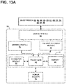
- FIG. 13A is a block diagram of an exemplary IMD, e.g., the systems of FIGS. 11-12 .
- FIG. 13B is another block diagram of an exemplary IMD (e.g., an implantable pulse generator) circuitry and associated leads employed in the systems of FIGS. 11-12 .
- IMD e.g., an implantable pulse generator
- FIGS. 1-13 Exemplary systems and methods shall be described with reference to FIGS. 1-13 . It will be apparent to one skilled in the art that elements or processes from one embodiment may be used in combination with elements or processes of the other embodiments, and that the possible embodiments of such methods and systems using combinations of features set forth herein is not limited to the specific embodiments shown in the Figures and/or described herein. Further, it will be recognized that the embodiments described herein may include many elements that are not necessarily shown to scale. Still further, it will be recognized that timing of the processes and the size and shape of various elements herein may be modified but still fall within the scope of the present disclosure, although certain timings, one or more shapes and/or sizes, or types of elements, may be advantageous over others.
- a plurality of electrocardiogram (ECG) recordings or signals may be measured, or monitored, using a plurality of external electrodes positioned about the surface, or skin, of a patient.
- the ECG signals may be used to evaluate and configured cardiac therapy such as, e.g., CRT.
- cardiac therapy such as, e.g., CRT.
- the ECG signals may be gathered or obtained noninvasively since, e.g., implantable electrodes may not be used to measure the ECG signals.
- the ECG signals may be used to determine cardiac electrical activation times, which may be used to generate various metrics (e.g., electrical heterogeneity information) that may be used by a user (e.g., physician) to optimize one or more settings, or parameters, of pacing therapy.
- metrics e.g., electrical heterogeneity information
- Electrode apparatus including external electrodes, display apparatus, and computing apparatus to noninvasively assist a user (e.g., a physician) in the evaluation of cardiac health and/or the configuration (e.g., optimization) of cardiac therapy.
- An exemplary system 100 including electrode apparatus 110 , display apparatus 130 , and computing apparatus 140 is depicted in FIG. 1 .
- the electrode apparatus 110 as shown includes a plurality of electrodes incorporated, or included, within a band wrapped around the chest, or torso, of a patient 14 .
- the electrode apparatus 110 is operatively coupled to the computing apparatus 140 (e.g., through one or wired electrical connections, wirelessly, etc.) to provide electrical signals from each of the electrodes to the computing apparatus 140 for analysis, evaluation, etc.
- Exemplary electrode apparatus may be described in U.S. Pat. No. 9,320,446 entitled “Bioelectric Sensor Device and Methods” filed Mar. 27, 2014 and issued on Mar. 26, 2016, which is incorporated herein by reference in its entirety. Further, exemplary electrode apparatus 110 will be described in more detail in reference to FIGS. 2-3 .
- the exemplary system 100 may further include imaging apparatus.
- the imaging apparatus may be any type of imaging apparatus configured to image, or provide images of, at least a portion of the patient in a noninvasive manner.
- the imaging apparatus may not use any components or parts that may be located within the patient to provide images of the patient except noninvasive tools such as contrast solution.
- the exemplary systems and methods described herein may further use imaging apparatus to provide noninvasive assistance to a user (e.g., a physician) to locate, or select, a pacing electrode or vector proximate the patient's heart in conjunction with the configuration of cardiac therapy.
- the exemplary systems and methods may provide image guided navigation that may be used to navigate leads including electrodes, leadless electrodes, wireless electrodes, catheters, etc., within the patient's body while also providing noninvasive cardiac therapy configuration including determining an effective, or optimal, A-V interval.
- Exemplary systems and methods that use imaging apparatus and/or electrode apparatus may be described in U.S. Pat. App. Pub. No. 2014/0371832 to Ghosh published on Dec. 18, 2014, U.S. Pat. App. Pub. No. 2014/0371833 to Ghosh et al. published on Dec. 18, 2014, U.S. Pat. App. Pub. No. 2014/0323892 to Ghosh et al. published on Oct. 30, 2014, U.S. Pat. App. Pub. No. 2014/0323882 to Ghosh et al. published on Oct. 20, 2014, each of which is incorporated herein by reference in its entirety.
- Exemplary imaging apparatus may be configured to capture x-ray images and/or any other alternative imaging modality.
- the imaging apparatus may be configured to capture images, or image data, using isocentric fluoroscopy, bi-plane fluoroscopy, ultrasound, computed tomography (CT), multi-slice computed tomography (MSCT), magnetic resonance imaging (MRI), high frequency ultrasound (HIFU), optical coherence tomography (OCT), intra-vascular ultrasound (IVUS), two dimensional (2D) ultrasound, three dimensional (3D) ultrasound, four dimensional (4D) ultrasound, intraoperative CT, intraoperative MRI, etc.
- CT computed tomography
- MSCT multi-slice computed tomography
- MRI magnetic resonance imaging
- HIFU high frequency ultrasound
- OCT optical coherence tomography
- IVUS intra-vascular ultrasound
- two dimensional (2D) ultrasound three dimensional (3D) ultrasound
- 4D four dimensional
- a plurality of images taken over time using the imaging apparatus may provide video frame, or motion picture, data. Additionally, the images may also be obtained and displayed in two, three, or four dimensions.
- four-dimensional surface rendering of the heart or other regions of the body may also be achieved by incorporating heart data or other soft tissue data from a map or from pre-operative image data captured by MRI, CT, or echocardiography modalities.
- Image datasets from hybrid modalities such as positron emission tomography (PET) combined with CT, or single photon emission computer tomography (SPECT) combined with CT, could also provide functional image data superimposed onto anatomical data, e.g., to be used to navigate implantable apparatus to target locations within the heart or other areas of interest.
- PET positron emission tomography
- SPECT single photon emission computer tomography
- the display apparatus 130 and the computing apparatus 140 may be configured to display and analyze data such as, e.g., electrical signals (e.g., electrocardiogram data), electrical activation times, electrical heterogeneity information, etc.
- data such as, e.g., electrical signals (e.g., electrocardiogram data), electrical activation times, electrical heterogeneity information, etc.
- one cardiac cycle, or one heartbeat, of a plurality of cardiac cycles, or heartbeats, represented by the electrical signals collected or monitored by the electrode apparatus 110 may be analyzed and evaluated for one or more metrics including activation times and electrical heterogeneity information that may be pertinent to the therapeutic nature of one or more parameters related to cardiac therapy such as, e.g., pacing parameters, lead location, etc.
- the QRS complex of a single cardiac cycle may be evaluated for one or more metrics such as, e.g., QRS onset, QRS offset, QRS peak, electrical heterogeneity information, electrical activation times, left ventricular or thoracic standard deviation of electrical activation times (LVED), standard deviation of activation-times (SDAT), average left ventricular or thoracic surrogate electrical activation times (LVAT), referenced to earliest activation time, QRS duration (e.g., interval between QRS onset to QRS offset), difference between average left surrogate and average right surrogate activation times, relative or absolute QRS morphology, difference between a higher percentile and a lower percentile of activation times (higher percentile may be 90%, 80%, 75%, 70%, etc.
- QRS onset e.g., QRS onset, QRS offset, QRS peak
- electrical heterogeneity information e.g., electrical activation times, left ventricular or thoracic standard deviation of electrical activation times (LV
- the display apparatus 130 and the computing apparatus 140 may be configured to analyze the electrical signals (ECG) over a plurality of cardiac cycles, or heartbeats, using the plurality of signals resulting in a plurality of electrical signals over a plurality of cardiac cycles, and then select a single cardiac cycle for further evaluation from the plurality of cardiac cycles.
- ECG electrical signals
- a more desirable cardiac cycle does not necessarily mean that the most “healthy” cardiac cycle is selected. Instead, a cardiac cycle having the desired signal characteristics for use in proper evaluation may be the cardiac cycle selected. Further, as described herein, the QRS complex of the electrical signal of the cardiac cycle may be the specific portion of the electrical signal corresponding to the cardiac cycle selected.
- the computing apparatus 140 may be a server, a personal computer, or a tablet computer.
- the computing apparatus 140 may be configured to receive input from input apparatus 142 and transmit output to the display apparatus 130 .
- the computing apparatus 140 may include data storage that may allow for access to processing programs or routines and/or one or more other types of data, e.g., for analyzing a plurality of electrical signals captured by the electrode apparatus 110 , for determining QRS onsets, QRS offsets, medians, modes, averages, peaks or maximum values, valleys or minimum values, for determining electrical activation times, for selecting a heartbeat or QRS complex based on one or more metrics or tests, for scoring heartbeats and QRS complexes based on one or more metrics or features of the heartbeats and QRS complexes, for driving a graphical user interface configured to noninvasively assist a user in configuring one or more pacing parameters, or settings, such as, e.g., A-V interval, V-V interval, for driving
- the computing apparatus 140 may be operatively coupled to the input apparatus 142 and the display apparatus 130 to, e.g., transmit data to and from each of the input apparatus 142 and the display apparatus 130 .
- the computing apparatus 140 may be electrically coupled to each of the input apparatus 142 and the display apparatus 130 using, e.g., analog electrical connections, digital electrical connections, wireless connections, bus-based connections, network-based connections, internet-based connections, etc.
- a user may provide input to the input apparatus 142 to view and/or select one or more pieces of configuration information related to the cardiac therapy.
- the input apparatus 142 is a keyboard, it is to be understood that the input apparatus 142 may include any apparatus capable of providing input to the computing apparatus 140 to perform the functionality, methods, and/or logic described herein.
- the input apparatus 142 may include a mouse, a trackball, a touchscreen (e.g., capacitive touchscreen, a resistive touchscreen, a multi-touch touchscreen, etc.), etc.
- the display apparatus 130 may include any apparatus capable of displaying information to a user, such as a graphical user interface 132 including one or more heartbeats, QRS complexes, pacing parameters, electrical heterogeneity information, textual instructions, graphical depictions of electrical activation information, graphical depictions of anatomy of a human heart, images or graphical depictions of the patient's heart, graphical depictions of locations of one or more electrodes, graphical depictions of a human torso, images or graphical depictions of the patient's torso, graphical depictions or actual images of implanted electrodes and/or leads, etc.
- the display apparatus 130 may include a liquid crystal display, an organic light-emitting diode screen, a touchscreen, a cathode ray tube display, etc.
- the processing programs or routines stored and/or executed by the computing apparatus 140 may include programs or routines for computational mathematics, matrix mathematics, decomposition algorithms, compression algorithms (e.g., data compression algorithms), calibration algorithms, image construction algorithms, signal processing algorithms (e.g., various filtering algorithms, Fourier transforms, fast Fourier transforms, etc.), standardization algorithms, comparison algorithms, vector mathematics, or any other processing required to implement one or more exemplary methods and/or processes described herein.
- compression algorithms e.g., data compression algorithms
- calibration algorithms e.g., image construction algorithms
- signal processing algorithms e.g., various filtering algorithms, Fourier transforms, fast Fourier transforms, etc.
- standardization algorithms e.g., various filtering algorithms, Fourier transforms, fast Fourier transforms, etc.
- comparison algorithms e.g., vector mathematics, or any other processing required to implement one or more exemplary methods and/or processes described herein.
- Data stored and/or used by the computing apparatus 140 may include, for example, electrical signal/waveform data from the electrode apparatus 110 (e.g., a plurality of QRS complexes), electrical activation times from the electrode apparatus 110 , graphics (e.g., graphical elements, icons, buttons, windows, dialogs, pull-down menus, graphic areas, graphic regions, 3D graphics, etc.), graphical user interfaces, results from one or more processing programs or routines employed according to the disclosure herein (e.g., electrical signals, electrical heterogeneity information, etc.), or any other data that may be necessary for carrying out the one and/or more processes or methods described herein.
- electrical signal/waveform data from the electrode apparatus 110 e.g., a plurality of QRS complexes
- graphics e.g., graphical elements, icons, buttons, windows, dialogs, pull-down menus, graphic areas, graphic regions, 3D graphics, etc.
- graphical user interfaces e.g., results from one or more processing programs or routines employed
- the exemplary systems and methods may be implemented using one or more computer programs executed on programmable computers, such as computers that include, for example, processing capabilities, data storage (e.g., volatile or non-volatile memory and/or storage elements), input devices, and output devices.
- Program code and/or logic described herein may be applied to input data to perform functionality described herein and generate desired output information.
- the output information may be applied as input to one or more other devices and/or methods as described herein or as would be applied in a known fashion.
- the one or more programs used to implement the systems, methods, and/or interfaces described herein may be provided using any programmable language, e.g., a high-level procedural and/or object orientated programming language that is suitable for communicating with a computer system. Any such programs may, for example, be stored on any suitable device, e.g., a storage media, that is readable by a general or special purpose program running on a computer system (e.g., including processing apparatus) for configuring and operating the computer system when the suitable device is read for performing the procedures described herein.
- a programmable language e.g., a high-level procedural and/or object orientated programming language that is suitable for communicating with a computer system.
- Any such programs may, for example, be stored on any suitable device, e.g., a storage media, that is readable by a general or special purpose program running on a computer system (e.g., including processing apparatus) for configuring and operating the computer system when the suitable device is read for performing the
- the exemplary systems and methods interfaces may be implemented using a computer readable storage medium, configured with a computer program, where the storage medium so configured causes the computer to operate in a specific and predefined manner to perform functions described herein.
- the exemplary systems and methods may be described as being implemented by logic (e.g., object code) encoded in one or more non-transitory media that includes code for execution and, when executed by a processor, is operable to perform operations such as the methods, processes, and/or functionality described herein.
- the computing apparatus 140 may be, for example, any fixed or mobile computer system (e.g., a controller, a microcontroller, a personal computer, mini computer, tablet computer, etc.).
- the exact configuration of the computing apparatus 140 is not limiting, and essentially any device capable of providing suitable computing capabilities and control capabilities (e.g., signal analysis, mathematical functions such as medians, modes, averages, maximum value determination, minimum value determination, slope determination, minimum slope determination, maximum slope determination, graphics processing, etc.) may be used.
- a digital file may be any medium (e.g., volatile or non-volatile memory, a CD-ROM, a punch card, magnetic recordable tape, etc.) containing digital bits (e.g., encoded in binary, trinary, etc.) that may be readable and/or writeable by computing apparatus 140 described herein.
- a file in user-readable format may be any representation of data (e.g., ASCII text, binary numbers, hexadecimal numbers, decimal numbers, graphically, etc.) presentable on any medium (e.g., paper, a display, etc.) readable and/or understandable by a user.
- ECGs monitored by the electrode apparatus 110 of the patient's heart may be useful to evaluate cardiac therapy being delivered to a patient.
- one, or a single, QRS complex of a single cardiac cycle may be useful to evaluate the patient's cardiac health and/or any cardiac therapy being delivered to the patient.
- Such ECGs or ECG signals of a patient's heart may be monitored, or determined, using electrode apparatus 110 as shown in FIG. 1 and in FIGS. 2-3 .
- the exemplary electrode apparatus 110 may be configured to measure body-surface potentials of a patient 14 and, more particularly, torso-surface potentials of a patient 14 . As shown in FIG.
- the exemplary electrode apparatus 110 may include a set, or array, of electrodes 112 , a strap 113 , and interface/amplifier circuitry 116 .
- the electrodes 112 may be attached, or coupled, to the strap 113 and the strap 113 may be configured to be wrapped around the torso of a patient 14 such that the electrodes 112 surround the patient's heart.
- the electrodes 112 may be positioned around the circumference of a patient 14 , including the posterior, lateral, posterolateral, anterolateral, and anterior locations of the torso of a patient 14 .
- the electrodes 112 may be electrically connected to interface/amplifier circuitry 116 via wired connection 118 .
- the interface/amplifier circuitry 116 may be configured to amplify the signals from the electrodes 112 and provide the signals to the computing apparatus 140 .
- Other exemplary systems may use a wireless connection to transmit the signals sensed by electrodes 112 to the interface/amplifier circuitry 116 and, in turn, the computing apparatus 140 , e.g., as channels of data.
- the interface/amplifier circuitry 116 may be electrically coupled to each of the computing apparatus 140 and the display apparatus 130 using, e.g., analog electrical connections, digital electrical connections, wireless connections, bus-based connections, network-based connections, internet-based connections, etc.
- the electrode apparatus 110 includes a strap 113
- any of a variety of mechanisms e.g., tape or adhesives, may be employed to aid in the spacing and placement of electrodes 112 .
- the strap 113 may include an elastic band, strip of tape, or cloth.
- the electrodes 112 may be placed individually on the torso of a patient 14 .
- electrodes 112 e.g., arranged in an array
- the electrodes 112 may be part of, or located within, two sections of material or two “patches.”
- One of the two sections or patches may be located on the anterior side of the torso of the patient 14 (to, e.g., monitor electrical signals representative of the anterior side of the patient's heart, measure surrogate cardiac electrical activation times representative of the anterior side of the patient's heart, etc.) and the other section or patch may be located on the posterior side of the torso of the patient 14 (to, e.g., monitor electrical signals representative of the posterior side of the patient's heart, measure surrogate cardiac electrical activation times representative of the posterior side of the patient's heart, etc.).
- the electrodes 112 may be arranged in a top row and bottom row that extend from the anterior side of the patient 14 across the left side of the patient 14 to the anterior side of the patient 14 . Yet still further, in other examples, the electrodes 112 may be arranged in a curve around the armpit area and may have an electrode-density that less dense on the right thorax that the other remaining areas.
- the electrodes 112 may be configured to surround the heart of the patient 14 and record, or monitor, the electrical signals associated with the depolarization and repolarization of the heart after the signals have propagated through the torso of a patient 14 .
- Each of the electrodes 112 may be used in a unipolar configuration to sense the torso-surface potentials that reflect the cardiac signals.
- the interface/amplifier circuitry 116 may also be coupled to a return or indifferent electrode (not shown) that may be used in combination with each electrode 112 for unipolar sensing. In some examples, there may be about 12 to about 50 electrodes 112 spatially distributed around the torso of a patient. Other configurations may have more or fewer electrodes 112 .
- the electrodes 112 may not be arranged or distributed in an array extending all the way around or completely around the patient 14 . Instead, the electrodes 112 may be arrange in an array that extends only part of the way or partially around the patient 14 . For example, the electrode 112 may be distributed on the anterior, posterior, and left sides of the patient with less or no electrodes proximate the right side (including posterior and anterior regions of the right side).
- the computing apparatus 140 may record and analyze the torso-surface potential signals sensed by electrodes 112 and amplified/conditioned by the interface/amplifier circuitry 116 .
- the computing apparatus 140 may be configured to analyze the signals from the electrodes 112 to provide electrocardiogram (ECG) signals, information, or data from the patient's heart as will be further described herein.
- ECG electrocardiogram
- the computing apparatus 140 may be configured to provide graphical user interfaces depicting the ECGs including QRS complexes obtained using the electrode apparatus 110 as well as other information related thereto. Exemplary systems and methods may noninvasively use the electrical information collected using the electrode apparatus 110 to evaluate a patient's cardiac health and evaluate and configure cardiac therapy being delivered to the patient.
- the electrode apparatus 110 may further include reference electrodes and/or drive electrodes to be, e.g. positioned about the lower torso of the patient 14 , that may be further used by the system 100 .
- the electrode apparatus 110 may include three reference electrodes, and the signals from the three reference electrodes may be combined to provide a reference signal.
- the electrode apparatus 110 may use of three caudal reference electrodes (e.g., instead of standard references used in Wilson Central Terminal) to get a “true’ unipolar signal with lesser noise from averaging three caudally located reference signals.
- FIG. 3 illustrates another exemplary electrode apparatus 110 that includes a plurality of electrodes 112 configured to surround the heart of the patient 14 and record, or monitor, the electrical signals associated with the depolarization and repolarization of the heart after the signals have propagated through the torso of the patient 14 .
- the electrode apparatus 110 may include a vest 114 upon which the plurality of electrodes 112 may be attached, or to which the electrodes 112 may be coupled.
- the plurality, or array, of electrodes 112 may be used to collect electrical information such as, e.g., surrogate electrical activation times. Similar to the electrode apparatus 110 of FIG. 2 , the electrode apparatus 110 of FIG.
- the electrodes 112 may be distributed over the torso of a patient 14 , including, for example, the posterior, lateral, posterolateral, anterolateral, and anterior locations of the torso of a patient 14 .
- the vest 114 may be formed of fabric with the electrodes 112 attached to the fabric.
- the vest 114 may be configured to maintain the position and spacing of electrodes 112 on the torso of the patient 14 . Further, the vest 114 may be marked to assist in determining the location of the electrodes 112 on the surface of the torso of the patient 14 . In some examples, there may be about 25 to about 256 electrodes 112 distributed around the torso of the patient 14 , though other configurations may have more or fewer electrodes 112 .
- the exemplary systems and methods may be used to provide noninvasive assistance to a user in the evaluation of a patient's cardiac health and/or evaluation and configuration of cardiac therapy being presently-delivered to the patient (e.g., by an implantable medical device).
- the exemplary systems and methods may be used to assist a user in the configuration and/or adjustment of one or more cardiac therapy settings for the cardiac therapy being delivered to a patient.
- the exemplary systems and methods may provide optimization of the A-V interval, or delay, of pacing therapy (e.g., left univentricular pacing therapy).
- FIG. 4 An exemplary method 200 of selecting a cardiac cycle, or heartbeat from a plurality of cardiac cycles, or heartbeats, is depicted in FIG. 4 . More specifically, in this embodiment, the QRS complexes of electrical signals representative of the cardiac cycle may be selected since, e.g., the QRS complexes may be used to determine activation times and electrical heterogeneity information.
- the method 200 includes monitoring electrical activity 202 of the patient using a plurality of external electrodes such as found on electrode apparatus 110 described herein.
- the electrical activity 202 may be monitored for a plurality of cardiac cycles or heartbeats. Further, the electrical activity 202 may be monitored for a selected period of time such as, e.g., five seconds.
- some of the signals with respect to cardiac cycles, or more specifically, the QRS complexes related thereto may be irregular or have other undesirable characteristics or features that makes the signals corresponding to the cardiac cycles (e.g., QRS complexes) undesirable for further analysis with respect to a patient's cardiac health or cardiac therapy being delivered to the patient.
- a more desirable signal representative of a cardiac cycle does not necessarily mean that the most “healthy” cardiac cycle is selected. Instead, a signal of a cardiac cycle having the desired signal characteristics for use in proper evaluation may be the cardiac cycle selected.
- the method 200 may analyze the electrical signals, or more specifically, the QRS complexes over a plurality of cardiac cycles to determine which cardiac cycle produced, or has, a desirable signal or QRS complex for further analysis.
- the method 200 may “filter out” undesirable signals during cardiac cycles, or heartbeats, from more desirable signals, and may, at least in one embodiment, determine the cardiac cycle, or heartbeat, and signal or QRS complex corresponding thereto that may be desirably used for further analysis.
- the method 200 may determine, or identify, the peak times of the plurality of QRS complexes within the plurality of signals over the plurality of cardiac cycles 204 .
- a graph of a plurality of electrical signals 230 over time are depicted in FIG. 5 .
- the plurality of electrical signals 230 include a plurality of cardiac cycles. In other words, the electrical signals 230 have been captured, or monitored, over a plurality of cardiac cycles.
- each of QRS peaks may be located within the plurality of signals 230 .
- Five QRS peaks 232 are identified in FIG. 5 corresponding to five cardiac cycles. Further, the time at which each of the QRS peaks 232 occurs may be referred to as QRS peak time 234 , each represented by a line.
- the peak times 234 may then be used to identify each of the QRS complexes 231 .
- a portion of each of the plurality of electrical signals 230 about each of the peak times 234 may be selected for further analysis.
- each of the plurality of electrical signals 230 may be “windowed” about their respective peak times 234 to provide segments of the plurality of electrical signals 230 that correspond to each cardiac cycle or QRS complex 231 .
- a graph of a plurality of electrical signals 230 over a single heartbeat or QRS complex 231 that has been window, or identified, from the peak time 234 at about 1780 milliseconds is depicted in FIG. 6 .
- identifying the portion of each of the plurality of electrical signals 230 about each of the peak times 234 may be executed by determining the onset and offset times of the QRS complex.
- Exemplary systems and methods of determining the onset and offset times of the QRS complex may be described in U.S. Prov. Pat. App. Ser. No. 62/471,938 filed on Mar. 15, 2017, and entitled “QRS OFFSET AND ONSET DETERMINATION,” U.S. Pat. App. Pub. No. 2017/0143976 A1 filed on Dec. 2, 2016, and entitled “DETERMINING ONSETS AND OFFSETS OF CARDIAC DEPOLARIZATION AND REPOLARIZATION WAVES,” U.S. Pat. App.
- the method 200 may further include generating one or more (or a plurality) of metrics for each QRS complex 231 over the plurality cardiac cycles 206 .
- five cardiac cycles (more specifically, in this example, five QRS complexes 231 ) are identified (see FIG. 5 ), and thus, one or more metrics may be generated, or calculated, for each of the five cardiac cycles. More specifically, in this example, one or more metrics may be generated, or calculated, for each of the five QRS complexes 231 corresponding to the five cardiac cycles.
- One or more of the metrics generated 206 may be described as using at least two, or two or more, signals of the plurality of signals 230 monitored, or captured, by at least two, or two or more, electrodes. Further, one or more metrics generate 206 may use various submetrics. For example, one or more metrics generate 206 may use a single-cycle submetric that is based on at least two of the plurality of electrical signals during the cardiac cycle that is being presently analyzed. In other words, the single-cycle submetric may only use electrical signal data recorded during the window of the particular cardiac cycle for which the metric is being generated.
- one or more metrics generate 206 may use a cycle-series submetric that is based on at least two of the plurality of electrical signals during, or over, at least two cardiac cycles.
- the cycle-series submetric may use electrical signal data recorded during multiple windows of the cardiac cycles, including the cardiac cycle for which the metric is being generated.
- the single-cycle submetric is described as using at least two of the plurality of electrical signals, it to be understood that the single-cycle submetric and/or the cycle-series submetric may use all of the electrical signals that are providing valid signals. Further, it to be understood that the single-cycle submetric and/or the cycle-series submetric may use a set of the electrical signals based on one or more pre-screening or filtering processes. Regardless, each of the submetrics may use two or more electrical signals. Additionally, each of the submetrics may be used to generate the one or more metrics generated 206 , which will be further used by the process 208 as will be further described herein.
- Exemplary single-cycle submetrics may include maximum amplitude, minimum amplitude, sum amplitude, R-R interval, peak-to-peak amplitude, dispersion (e.g., standard deviation, variance, range, etc.), polarity, window length, etc.
- the maximum amplitude 240 may be the value of the largest signal of at least two of the plurality of signals 230 (e.g., all of the plurality of signals) at peak time 234 .
- the minimum amplitude 242 may be the value of the smallest signal at least two (e.g., all of the plurality of signals) of the plurality of signals 230 at peak time 234 .
- the sum amplitude 244 may be the sum of at least two of all amplitude values of the plurality of signals 230 (e.g., all of the plurality of signals) at peak time 234 .
- the R-R interval may be the time value from the peak time 234 to the peak time 234 of either the previous QRS complex or following QRS complex.
- Exemplary cycle-series submetrics may be medians, modes, averages, quantiles, (maximum value ⁇ minimum value)/2, median after dropping outliers (e.g., at least one high value, at least one low value, etc.), average after dropping outliers (e.g., at least one high value, at least one low value, etc.), standard deviation, etc. of the single-cycle submetrics generated, or calculated, for each cardiac cycle or QRS complex.
- contact metrics could be used to eliminate signals from the calculations (such as medians), for example, if they have low peak-to-peak amplitudes or the like, to keep the calculations from getting artificially deflated.
- pre-processing step or processes may be used before computing any of the metrics or submetrics to eliminate outliers or undesired signal data.
- each metric generated for each cardiac cycle, or QRS complex may be a fraction, or ratio, of the single-cycle submetric, which may be based on at least two of the plurality of electrical signals 230 during the present cardiac cycle being analyzed, the cycle-series submetric, which may be based on at least two of the plurality of electrical signals 230 during at least two cardiac cycles.
- one metric could be generated based on a single-cycle submetric, which is based on all of the plurality of electrical signals 230 of the QRS complex having a peak time 234 of 1780 milliseconds ( FIG. 6 ), and a cycle-series submetric, which is based on all of the plurality of signals 230 at each of the five peak times 234 ( FIG. 5 ).
- a maximum amplitude metric, a minimum amplitude metric, a sum amplitude metric, and a R-R interval metric may be generated as follows:
- the method 200 may then select one or more of the cardiac cycles or heartbeats 208 based on at least the metrics.
- the selected one or more cardiac cycles or heartbeats 208 may then be used for further analysis of the patient's cardiac functionality and/or cardiac therapy being delivered to the patient.
- a single cardiac cycles or heartbeat may be selected 208 .
- selection one or more of the cardiac cycles or heartbeats 208 based on at least the generated metrics may be performed a plurality of different ways.
- One exemplary method, or process, 208 of selection one or more of the cardiac cycles, or heartbeats, 208 based on at least the generated metrics is depicted in FIGS. 7-10 .
- the method 208 of FIG. 7 may include comparing each metric of each cardiac cycle, or heartbeat, to a threshold 210 , and then scoring each cardiac cycle, or heartbeat, 212 based on the comparison of each metric.
- a table of exemplary metrics generated from the plurality of electrical signals 230 for five heartbeats is depicted in FIG. 8 . Specifically, a maximum amplitude metric (M max ), a minimum amplitude metric (M min ), a sum amplitude metric (M sum ), and a R-R interval metric (M rr ) were generated for each of the five heartbeats as shown.
- Each value of each metric for each heartbeat may then be compared to various thresholds to determine a score for each metric for each heartbeat. It is to be understood that a plurality of different thresholds may be used in a many different way as well as the scoring.
- One exemplary set of thresholds are depicted in the following Table 1:
- Each of the metrics depicted in FIG. 8 may be compared to the thresholds of Table 1 above, and assigned a score of 0 if the value of the metric passes the threshold and a score of 1 if the value of the metric fails the threshold as shown in the table of FIG. 9 . Additionally shown, a score for each heartbeat may be tabulated by adding all the scores for the heartbeat as shown in the bottom row of the table of FIG. 9 . In other words, each value in a column, each of which represents a heartbeat or cardiac cycle, may be added together to provide a score for that particular heartbeat or cardiac cycle.
- the exemplary method, or process, 208 of selecting a cardiac cycle, or heartbeat may use, among other things, these scores, which, as described herein, are based on both of a single-cycle submetric and a cycle-series submetric to select one or more cardiac cycles, or heartbeats, for further analysis and evaluation.
- an electrode contact metric may be representative of an amount of the plurality of electrodes that captured a valid electrocardiographic signal from the tissue of the patient during the cardiac cycle.
- the regional electrode contact metric may be representative of an amount of the plurality of electrodes located proximate a selected region of the patient that captured a valid electrocardiographic signal from the tissue in the selection region of the patient during the cardiac cycle.
- an electrode contact metric may be computed as a percentage of electrodes with valid electrocardiographic signals over each cardiac cycle and this metric may be used to select a cardiac cycle in addition to the other signal quality metrics described herein.
- the cardiac cycle with a maximum electrode contact metric may be used to resolve the tie and select a cardiac cycle for processing of activation times.
- An electrode contact metric may be computed for one or more regions of the torso such as e.g., the right thorax and/or the left thorax.
- cardiac cycles with a electrode contact metric less than a threshold may not be eligible for selection. Exemplary values of such threshold may be 70%, 65%, 60%, etc.
- Exemplary systems and methods for use in providing electrode contact metrics and identifying electrodes provide valid sensing signals may be described in U.S.
- the scoring as described with respect to Table 1 could be “weighted.”
- the R-R interval metric could have a fail score of 2.
- some of the metrics could be analyzed first, beats removed, and then the remainder of the metrics may be analyzed for the remaining beats.
- the R-R interval metric may be analyzed, and if any beat is removed, the beat following removed beat may be removed as well as the prior beat, potentially. Then, the remainder of the metrics may be used to choose the beat.
- the R-R interval metric may be worth 1.5 and sum metric may be worth 0.5.
- the exemplary method 208 may include removing from consideration of selection cardiac cycles, or heartbeats, based on the score 214 .
- the score may be compared to a scoring threshold value, and depending on whether the score is greater than, equal to, or less than the scoring threshold value may determine whether the cardiac cycle is kept or removed from consideration.
- any cardiac cycle, or heartbeat, having or defining a score greater than a scoring threshold value may be removed from further consideration and, conversely, any cardiac cycle, or heartbeat, having or defining a score less than or equal to the scoring threshold value may be remaining.
- the scoring threshold value may be “2.” As such, any heartbeats having a score greater than 2 may be disregarded, and not further considered for selection.
- the method 208 may end, and the final remaining heartbeat or cardiac cycle may be selected for further evaluation.
- the exemplary method 208 may further include removing from consideration of selection heartbeats that follow heartbeats having a score greater than the scoring threshold value.
- the heartbeat occurring immediately after a heartbeat that fails to be less than the threshold value may also be removed from further consideration of selection. For example, if a particular heartbeat such as “Beat 17” is removed for having a score greater than the scoring threshold, then the following “Beat 18” may also be removed from consideration.
- the beat preceding a heartbeat that with a failed threshold may be removed from consideration. For example, if a particular heartbeat such as “Beat 17” is removed for having a score greater than the scoring threshold, then the preceding “Beat 16” may also be removed from consideration.
- the first cardiac cycle in the plurality of cardiac cycle from the plurality of signals may be removed from consideration 218 .
- the last cardiac cycle in the plurality of cardiac cycles from the plurality of signals may be removed from consideration 220 .
- the earliest cardiac cycle still remaining may be selected for further evaluation and analysis 222 .
- FIG. 10 An exemplary selection process of a heartbeat, or cardiac cycle, from the five heartbeats of FIGS. 8-9 is depicted in FIG. 10 .
- the five heartbeats, or cardiac cycles are represented by boxes and are evaluated chronologically from left to right using the method 208 .
- the box representing the heartbeat is represented by dashed lines, and is then removed from the figure for the next step or process.
- the heartbeats with a score greater than 2, i.e., the scoring threshold value may be removed 214 .
- “Beat 4” has a score of 3, which is greater than 2, and thus “Beat 4” may be removed.
- any beat following a beat with a score greater than 2, i.e., the scoring threshold value may be removed 216 .
- Four beats remain, and thus “Beat 5,” which follows “Beat 4,” may be removed.
- the first beat of the plurality beats may be removed 218 , and thus, “Beat 1” is removed. Still further, although more than one heartbeat remains, the last beat of the plurality beats has already been removed, and thus, no beat is removed in process 220 . Lastly, if more than one heartbeat remains, the earliest remaining heartbeat may be selected for further evaluation and analysis 222 . Since “Beat 2” and “Beat 3” remains, “Beat 3” is removed leaving “Beat 2” to be selected 224 since “Beat 2” occurs earlier than “Beat 3.”
- the exemplary systems and methods may be described as using QRS complex quality ranking.
- QRS complex quality ranking For instance, several metrics are used to compare electrical characteristics at a single pre-defined time point for each beat within the 5-second period against that of the median value for all beats across multiple body surface electrodes. Such metrics include: maximum and minimum signal values, sum of all signal values, and peak-to-peak interval. The metrics for each beat are compared to a threshold and are passed or failed for each characteristic. Other metrics may include percentage of electrodes that are in good contact and measure valid ECG signals for each QRS complex as contact for a given electrode and consequently the quality of signal may be variable over the 5-second period. Metrics of quality of signal or contact may be measured based on skin-electrode impedance and amplitude.
- a score using the pass or fail assessments may then be used to determine which beats are irregular from the median beat value and are likely not representative of the electrical conduction for the current pacing parameters. These irregular beats are removed from the candidate pool. Additional candidate beats are removed for following irregular beats and for being at the beginning or end of the signal collection.
- the exemplary systems and methods may collect five seconds of data for each pacing configuration. However, it may be computationally expensive and redundant to process all beats in each 5-second clip for CRT optimization. Thus, the exemplary systems and methods may be described as quantifying and scoring the quality of each beat against all others in the time series, and then determine which QRS complex to process additionally. The quality check may identify irregular beats, such as PVCs, and the selection process selects the beat that is most representative of the median.
- irregular beats such as PVCs
- the exemplary systems and methods described herein may be used with respect to the implantation and configuration of an implantable medical device (IMD) and/or one or more leads configured to be located proximate one or more portions of a patient's heart.
- IMD implantable medical device
- the exemplary systems and methods may be used in conjunction with an exemplary therapy system 10 described herein with reference to FIGS. 11-13 .
- FIG. 11 is a conceptual diagram illustrating an exemplary therapy system 10 that may be used to deliver pacing therapy to a patient 14 .
- Patient 14 may, but not necessarily, be a human.
- the therapy system 10 may include an implantable medical device 16 (IMD), which may be coupled to leads 18 , 20 , 22 .
- IMD 16 may be, e.g., an implantable pacemaker, cardioverter, and/or defibrillator, that delivers, or provides, electrical signals to and/or measures, or monitors electrical signals from the heart 12 of the patient 14 via electrodes coupled to one or more of the leads 18 , 20 , 22 .
- the leads 18 , 20 , 22 extend into the heart 12 of the patient 14 to sense electrical activity of the heart 12 and/or to deliver electrical stimulation to the heart 12 .
- the right ventricular (RV) lead 18 extends through one or more veins (not shown), the superior vena cava (not shown), and the right atrium 26 , and into the right ventricle 28 .
- the left ventricular (LV) coronary sinus lead 20 extends through one or more veins, the vena cava, the right atrium 26 , and into the coronary sinus 30 to a region adjacent to the free wall of the left ventricle 32 of the heart 12 .
- the right atrial (RA) lead 22 extends through one or more veins and the vena cava, and into the right atrium 26 of the heart 12 .
- the system 10 includes a RV lead 18 , it is to be understood the exemplary systems and methods described herein may not utilize the electrodes located on the RV lead 18 for sensing and/or pacing. Further, it is to be understood that the system 10 is merely one example, and that the exemplary systems and methods described herein may utilize systems that do not include a RV lead 18 (e.g., for sensing and/or pacing).
- the IMD 16 may sense, among other things, electrical signals attendant to the depolarization and repolarization of the heart 12 via electrodes coupled to at least one of the leads 18 , 20 , 22 .
- the IMD 16 provides pacing therapy (e.g., pacing pulses) to the heart 12 based on the electrical signals sensed within the heart 12 .
- the IMD 16 may be operable to adjust one or more parameters associated with the pacing therapy such as, e.g., A-V delay and other various timings, pulse wide, amplitude, voltage, burst length, etc.
- the IMD 16 may be operable to use various electrode configurations to deliver pacing therapy, which may be unipolar, bipolar, quadripoloar, or further multipolar.
- a multipolar lead may include several electrodes that can be used for delivering pacing therapy.
- a multipolar lead system may provide, or offer, multiple electrical vectors to pace from.
- a pacing vector may include at least one cathode, which may be at least one electrode located on at least one lead, and at least one anode, which may be at least one electrode located on at least one lead (e.g., the same lead, or a different lead) and/or on the casing, or can, of the IMD. While improvement in cardiac function as a result of the pacing therapy may primarily depend on the cathode, the electrical parameters like impedance, pacing threshold voltage, current drain, longevity, etc.
- the IMD 16 may be more dependent on the pacing vector, which includes both the cathode and the anode.
- the IMD 16 may also provide defibrillation therapy and/or cardioversion therapy via electrodes located on at least one of the leads 18 , 20 , 22 . Further, the IMD 16 may detect arrhythmia of the heart 12 , such as fibrillation of the ventricles 28 , 32 , and deliver defibrillation therapy to the heart 12 in the form of electrical pulses.
- IMD 16 may be programmed to deliver a progression of therapies, e.g., pulses with increasing energy levels, until a fibrillation of heart 12 is stopped.
- FIGS. 12A-12B are conceptual diagrams illustrating the IMD 16 and the leads 18 , 20 , 22 of therapy system 10 of FIG. 11 in more detail.
- the leads 18 , 20 , 22 may be electrically coupled to a therapy delivery module (e.g., for delivery of pacing therapy), a sensing module (e.g., for sensing one or more signals from one or more electrodes), and/or any other modules of the IMD 16 via a connector block 34 .
- the proximal ends of the leads 18 , 20 , 22 may include electrical contacts that electrically couple to respective electrical contacts within the connector block 34 of the IMD 16 .
- the leads 18 , 20 , 22 may be mechanically coupled to the connector block 34 with the aid of set screws, connection pins, or another suitable mechanical coupling mechanism.
- Each of the leads 18 , 20 , 22 includes an elongated insulative lead body, which may carry a number of conductors (e.g., concentric coiled conductors, straight conductors, etc.) separated from one another by insulation (e.g., tubular insulative sheaths).
- bipolar electrodes 40 , 42 are located proximate to a distal end of the lead 18 .
- bipolar electrodes 44 , 45 , 46 , 47 are located proximate to a distal end of the lead 20 and bipolar electrodes 48 , 50 are located proximate to a distal end of the lead 22 .
- the electrodes 40 , 44 , 45 , 46 , 47 , 48 may take the form of ring electrodes, and the electrodes 42 , 50 may take the form of extendable helix tip electrodes mounted retractably within the insulative electrode heads 52 , 54 , 56 , respectively.
- Each of the electrodes 40 , 42 , 44 , 45 , 46 , 47 , 48 , 50 may be electrically coupled to a respective one of the conductors (e.g., coiled and/or straight) within the lead body of its associated lead 18 , 20 , 22 , and thereby coupled to a respective one of the electrical contacts on the proximal end of the leads 18 , 20 , 22 .
- electrodes 44 , 45 , 46 and 47 may have an electrode surface area of about 5.3 mm 2 to about 5.8 mm 2 . Electrodes 44 , 45 , 46 , and 47 may also be referred to as LV 1 , LV 2 , LV 3 , and LV 4 , respectively.
- the LV electrodes i.e., left ventricle electrode 1 (LV 1 ) 44 , left ventricle electrode 2 (LV 2 ) 45 , left ventricle electrode 3 (LV 3 ) 46 , and left ventricle 4 (LV 4 ) 47 etc.
- the LV electrodes i.e., left ventricle electrode 1 (LV 1 ) 44 , left ventricle electrode 2 (LV 2 ) 45 , left ventricle electrode 3 (LV 3 ) 46 , and left ventricle 4 (LV 4 ) 47 etc.
- the LV electrodes i.e., left ventricle electrode 1 (LV 1 ) 44 , left ventricle electrode 2 (LV 2 ) 45
- electrode 44 may be a distance of, e.g., about 21 millimeters (mm), away from electrode 45 , electrodes 45 and 46 may be spaced a distance of, e.g., about 1.3 mm to about 1.5 mm, away from each other, and electrodes 46 and 47 may be spaced a distance of, e.g. 20 mm to about 21 mm, away from each other.
- mm millimeters
- the electrodes 40 , 42 , 44 , 45 , 46 , 47 , 48 , 50 may further be used to sense electrical signals (e.g., morphological waveforms within electrograms (EGM)) attendant to the depolarization and repolarization of the heart 12 .
- the sensed electrical signals may be used to adjust one or more pacing parameters such as, e.g., A-V interval, V-V interval, etc. to provide optimal and/or effective cardiac functionality.
- the electrical signals are conducted to the IMD 16 via the respective leads 18 , 20 , 22 .
- the IMD 16 may also deliver pacing pulses via the electrodes 40 , 42 , 44 , 45 , 46 , 47 , 48 , 50 to cause depolarization of cardiac tissue of the patient's heart 12 .
- the IMD 16 includes one or more housing electrodes, such as housing electrode 58 , which may be formed integrally with an outer surface of a housing 60 (e.g., hermetically-sealed housing) of the IMD 16 or otherwise coupled to the housing 60 . Any of the electrodes 40 , 42 , 44 , 45 , 46 , 47 , 48 , 50 may be used for unipolar sensing or pacing in combination with the housing electrode 58 .
- any of electrodes 40 , 42 , 44 , 45 , 46 , 47 , 48 , 50 , 58 may be used in combination to form a sensing vector, e.g., a sensing vector that may be used to evaluate and/or analyze the effectiveness of pacing therapy. It is to be understood by those skilled in the art that other electrodes can also be selected to define, or be used for, pacing and sensing vectors. Further, any of electrodes 40 , 42 , 44 , 45 , 46 , 47 , 48 , 50 , 58 , when not being used to deliver pacing therapy, may be used to sense electrical activity during pacing therapy.
- the housing 60 may enclose a therapy delivery module that may include a stimulation generator for generating cardiac pacing pulses and defibrillation or cardioversion shocks, as well as a sensing module for monitoring electrical signals of the patient's heart (e.g., the patient's heart rhythm).
- the leads 18 , 20 , 22 may also include elongated electrodes 62 , 64 , 66 , respectively, which may take the form of a coil.
- the IMD 16 may deliver defibrillation shocks to the heart 12 via any combination of the elongated electrodes 62 , 64 , 66 and the housing electrode 58 .
- the electrodes 58 , 62 , 64 , 66 may also be used to deliver cardioversion pulses to the heart 12 . Further, the electrodes 62 , 64 , 66 may be fabricated from any suitable electrically conductive material, such as, but not limited to, platinum, platinum alloy, and/or other materials known to be usable in implantable defibrillation electrodes.
- any of electrodes 62 , 64 , 66 may be used to sense electrical activity (e.g., for use in determining electrode effectiveness, for use in analyzing pacing therapy effectiveness, etc.) and may be used in combination with any of electrodes 40 , 42 , 44 , 45 , 46 , 47 , 48 , 50 , 58 .
- the RV elongated electrode 62 may be used to sense electrical activity of a patient's heart during the delivery of pacing therapy (e.g., in combination with the housing electrode 58 , or defibrillation electrode-to-housing electrode vector).
- the therapy system may include epicardial leads and/or patch electrodes instead of or in addition to the transvenous leads 18 , 20 , 22 illustrated in FIG. 11 .
- the therapy system 10 may be implanted in/around the cardiac space without transvenous leads (e.g., leadless/wireless pacing systems) or with leads implanted (e.g., implanted transvenously or using approaches) into the left chambers of the heart (in addition to or replacing the transvenous leads placed into the right chambers of the heart as illustrated in FIG. 11 ).
- An exemplary leadless system may be described in U.S.
- the IMD 16 need not be implanted within the patient 14 .
- the IMD 16 may deliver various cardiac therapies to the heart 12 via percutaneous leads that extend through the skin of the patient 14 to a variety of positions within or outside of the heart 12 .
- the system 10 may utilize wireless pacing (e.g., using energy transmission to the intracardiac pacing component(s) via ultrasound, inductive coupling, RF, etc.) and sensing cardiac activation using electrodes on the can/housing and/or on subcutaneous leads.
- therapy systems that provide electrical stimulation therapy to the heart 12
- therapy systems may include any suitable number of leads coupled to the IMD 16 , and each of the leads may extend to any location within or proximate to the heart 12 .
- other examples of therapy systems may include less than or more than three transvenous leads.
- the therapy system that provides pacing, or electrical stimulation, therapy to the heart 12 may only provide left univentricular pacing therapy with using, or including, sensing or pacing electrodes located in the left ventricle.
- At least one pacing and/or sensing electrode may be located in the patient's left ventricle and at least one pacing and/or sensing electrode may be located in one or both the right atrium and left atrium.
- other therapy systems may include a single lead that extends from the IMD 16 into the right atrium 26 or the right ventricle 28 , or two leads that extend into a respective one of the right atrium 26 and the right ventricle 28 .
- FIG. 13A is a functional block diagram of one exemplary configuration of the IMD 16 .
- the IMD 16 may include a control module 81 , a therapy delivery module 84 (e.g., which may include a stimulation generator), a sensing module 86 , and a power source 90 .
- a therapy delivery module 84 e.g., which may include a stimulation generator
- a sensing module 86 e.g., which may include a stimulation generator
- a power source 90 e.g., a power source 90 .
- the control module 81 may include a processor 80 , memory 82 , and a telemetry module 88 .
- the memory 82 may include computer-readable instructions that, when executed, e.g., by the processor 80 , cause the IMD 16 and/or the control module 81 to perform various functions attributed to the IMD 16 and/or the control module 81 described herein.
- the memory 82 may include any volatile, non-volatile, magnetic, optical, and/or electrical media, such as a random-access memory (RAM), read-only memory (ROM), non-volatile RAM (NVRAM), electrically-erasable programmable ROM (EEPROM), flash memory, and/or any other digital media.
- An exemplary capture management module may be the left ventricular capture management (LVCM) module described in U.S. Pat. No. 7,684,863 entitled “LV THRESHOLD MEASUREMENT AND CAPTURE MANAGEMENT” and issued Mar. 23, 2010, which is incorporated herein by reference in its entirety.
- LVCM left ventricular capture management
- the processor 80 of the control module 81 may include any one or more of a microprocessor, a controller, a digital signal processor (DSP), an application specific integrated circuit (ASIC), a field-programmable gate array (FPGA), and/or equivalent discrete or integrated logic circuitry.
- the processor 80 may include multiple components, such as any combination of one or more microprocessors, one or more controllers, one or more DSPs, one or more ASICs, and/or one or more FPGAs, as well as other discrete or integrated logic circuitry.
- the functions attributed to the processor 80 herein may be embodied as software, firmware, hardware, or any combination thereof.
- the control module 81 may control the therapy delivery module 84 to deliver therapy (e.g., electrical stimulation therapy such as pacing) to the heart 12 according to a selected one or more therapy programs, which may be stored in the memory 82 . More, specifically, the control module 81 (e.g., the processor 80 ) may control various parameters of the electrical stimulus delivered by the therapy delivery module 84 such as, e.g., A-V delays, V-V delays, pacing pulses with the amplitudes, pulse widths, frequency, or electrode polarities, etc., which may be specified by one or more selected therapy programs (e.g., A-V and/or V-V delay adjustment programs, pacing therapy programs, pacing recovery programs, capture management programs, etc.).
- therapy programs e.g., electrical stimulation therapy such as pacing
- the therapy delivery module 84 is electrically coupled to electrodes 40 , 42 , 44 , 45 , 46 , 47 , 48 , 50 , 58 , 62 , 64 , 66 , e.g., via conductors of the respective lead 18 , 20 , 22 , or, in the case of housing electrode 58 , via an electrical conductor disposed within housing 60 of IMD 16 .
- Therapy delivery module 84 may be configured to generate and deliver electrical stimulation therapy such as pacing therapy to the heart 12 using one or more of the electrodes 40 , 42 , 44 , 45 , 46 , 47 , 48 , 50 , 58 , 62 , 64 , 66 .
- therapy delivery module 84 may deliver pacing stimulus (e.g., pacing pulses) via ring electrodes 40 , 44 , 45 , 46 , 47 , 48 coupled to leads 18 , 20 , 22 and/or helical tip electrodes 42 , 50 of leads 18 , 22 . Further, for example, therapy delivery module 84 may deliver defibrillation shocks to heart 12 via at least two of electrodes 58 , 62 , 64 , 66 . In some examples, therapy delivery module 84 may be configured to deliver pacing, cardioversion, or defibrillation stimulation in the form of electrical pulses. In other examples, therapy delivery module 84 may be configured deliver one or more of these types of stimulation in the form of other signals, such as sine waves, square waves, and/or other substantially continuous time signals.
- pacing stimulus e.g., pacing pulses
- therapy delivery module 84 may deliver defibrillation shocks to heart 12 via at least two of electrodes 58 , 62 ,
- the IMD 16 may further include a switch module 85 and the control module 81 (e.g., the processor 80 ) may use the switch module 85 to select, e.g., via a data/address bus, which of the available electrodes are used to deliver therapy such as pacing pulses for pacing therapy, or which of the available electrodes are used for sensing.
- the switch module 85 may include a switch array, switch matrix, multiplexer, or any other type of switching device suitable to selectively couple the sensing module 86 and/or the therapy delivery module 84 to one or more selected electrodes. More specifically, the therapy delivery module 84 may include a plurality of pacing output circuits.
- Each pacing output circuit of the plurality of pacing output circuits may be selectively coupled, e.g., using the switch module 85 , to one or more of the electrodes 40 , 42 , 44 , 45 , 46 , 47 , 48 , 50 , 58 , 62 , 64 , 66 (e.g., a pair of electrodes for delivery of therapy using a bipolar or multipolar pacing vector).
- each electrode can be selectively coupled to one of the pacing output circuits of the therapy delivery module using the switching module 85 .
- the sensing module 86 is coupled (e.g., electrically coupled) to sensing apparatus, which may include, among additional sensing apparatus, the electrodes 40 , 42 , 44 , 45 , 46 , 47 , 48 , 50 , 58 , 62 , 64 , 66 to monitor electrical activity of the heart 12 , e.g., electrocardiogram (ECG)/electrogram (EGM) signals, etc.
- ECG electrocardiogram
- ECM electrolectrogram
- the ECG/EGM signals may be used to measure or monitor activation times (e.g., ventricular activation times, etc.), heart rate (HR), heart rate variability (HRV), heart rate turbulence (HRT), deceleration/acceleration capacity, deceleration sequence incidence, T-wave alternans (TWA), P-wave to P-wave intervals (also referred to as the P-P intervals or A-A intervals), R-wave to R-wave intervals (also referred to as the R-R intervals or V-V intervals), P-wave to QRS complex intervals (also referred to as the P-R intervals, A-V intervals, or P-Q intervals), QRS-complex morphology, ST segment (i.e., the segment that connects the QRS complex and the T-wave), T-wave changes, QT intervals, electrical vectors, etc.
- activation times e.g., ventricular activation times, etc.
- HR heart rate
- HRV heart rate variability
- HRT
- the switch module 85 may also be used with the sensing module 86 to select which of the available electrodes are used, or enabled, to, e.g., sense electrical activity of the patient's heart (e.g., one or more electrical vectors of the patient's heart using any combination of the electrodes 40 , 42 , 44 , 45 , 46 , 47 , 48 , 50 , 58 , 62 , 64 , 66 ).
- the switch module 85 may also be used with the sensing module 86 to select which of the available electrodes are not to be used (e.g., disabled) to, e.g., sense electrical activity of the patient's heart (e.g., one or more electrical vectors of the patient's heart using any combination of the electrodes 40 , 42 , 44 , 45 , 46 , 47 , 48 , 50 , 58 , 62 , 64 , 66 ), etc.
- the control module 81 may select the electrodes that function as sensing electrodes via the switch module within the sensing module 86 , e.g., by providing signals via a data/address bus.
- sensing module 86 includes a channel that includes an amplifier with a relatively wider pass band than the R-wave or P-wave amplifiers. Signals from the selected sensing electrodes may be provided to a multiplexer, and thereafter converted to multi-bit digital signals by an analog-to-digital converter for storage in memory 82 , e.g., as an electrogram (EGM). In some examples, the storage of such EGMs in memory 82 may be under the control of a direct memory access circuit.
- EGM electrogram
- control module 81 may operate as an interrupt driven device, and may be responsive to interrupts from pacer timing and control module, where the interrupts may correspond to the occurrences of sensed P-waves and R-waves and the generation of cardiac pacing pulses. Any necessary mathematical calculations may be performed by the processor 80 and any updating of the values or intervals controlled by the pacer timing and control module may take place following such interrupts.
- a portion of memory 82 may be configured as a plurality of recirculating buffers, capable of holding one or more series of measured intervals (e.g., intrinsic A-V conduction times), which may be analyzed by, e.g., the processor 80 in response to the occurrence of a pace or sense interrupt to determine whether the patient's heart 12 is presently exhibiting atrial or ventricular tachyarrhythmia.
- measured intervals e.g., intrinsic A-V conduction times
- the pacer timing and control module may include programmable counters which control the basic time intervals associated with DDD, VVI, DVI, VDD, AAI, DDI, DDDR, VVIR, DVIR, VDDR, AAIR, DDIR and other modes of single and dual chamber pacing.
- D may indicate dual chamber
- V may indicate a ventricle
- I may indicate inhibited pacing (e.g., no pacing)
- A” may indicate an atrium.
- the first letter in the pacing mode may indicate the chamber that is paced
- the second letter may indicate the chamber in which an electrical signal is sensed
- the third letter may indicate the chamber in which the response to sensing is provided.
- the telemetry module 88 of the control module 81 may include any suitable hardware, firmware, software, or any combination thereof for communicating with another device, such as a programmer.
- the telemetry module 88 may receive downlink telemetry from and send uplink telemetry to a programmer with the aid of an antenna, which may be internal and/or external.
- the processor 80 may provide the data to be uplinked to a programmer and the control signals for the telemetry circuit within the telemetry module 88 , e.g., via an address/data bus.
- the telemetry module 88 may provide received data to the processor 80 via a multiplexer.
- the various components of the IMD 16 are further coupled to a power source 90 , which may include a rechargeable or non-rechargeable battery.
- a power source 90 may include a rechargeable or non-rechargeable battery.
- a non-rechargeable battery may be selected to last for several years, while a rechargeable battery may be inductively charged from an external device, e.g., on a daily or weekly basis.
- FIG. 13B is another embodiment of a functional block diagram for IMD 16 .
- FIG. 13B depicts bipolar RA lead 22 , bipolar RV lead 18 , and bipolar LV CS lead 20 without the LA CS pace/sense electrodes and coupled with an implantable pulse generator (IPG) circuit 31 having programmable modes and parameters of a bi-ventricular DDD/R type known in the pacing art.
- IPG implantable pulse generator
- the sensor signal processing circuit 91 indirectly couples to the timing circuit 43 and via data and control bus to microcomputer circuitry 33 .
- the IPG circuit 31 is illustrated in a functional block diagram divided generally into a microcomputer circuit 33 and a pacing circuit 21 .
- the pacing circuit 21 includes the digital controller/timer circuit 43 , the output amplifiers circuit 51 , the sense amplifiers circuit 55 , the RF telemetry transceiver 41 , the activity sensor circuit 35 as well as a number of other circuits and components described below.
- Crystal oscillator circuit 89 provides the basic timing clock for the pacing circuit 21 while battery 29 provides power.
- Power-on-reset circuit 87 responds to initial connection of the circuit to the battery for defining an initial operating condition and similarly, resets the operative state of the device in response to detection of a low battery condition.
- Reference mode circuit 37 generates stable voltage reference and currents for the analog circuits within the pacing circuit 21 .
- Analog-to-digital converter (ADC) and multiplexer circuit 39 digitize analog signals and voltage to provide, e.g., real time telemetry of cardiac signals from sense amplifiers 55 for uplink transmission via RF transmitter and receiver circuit 41 .
- Voltage reference and bias circuit 37 , ADC and multiplexer 39 , power-on-reset circuit 87 , and crystal oscillator circuit 89 may correspond to any of those used in exemplary implantable cardiac pacemakers.
- the signals output by one or more physiologic sensors are employed as a rate control parameter (RCP) to derive a physiologic escape interval.
- RCP rate control parameter
- the escape interval is adjusted proportionally to the patient's activity level developed in the patient activity sensor (PAS) circuit 35 in the depicted, exemplary IPG circuit 31 .
- the patient activity sensor 27 is coupled to the IPG housing and may take the form of a piezoelectric crystal transducer. An output signal of the patient activity sensor 27 may be processed and used as a RCP.
- Sensor 27 generates electrical signals in response to sensed physical activity that are processed by activity circuit 35 and provided to digital controller/timer circuit 43 .
- Activity circuit 35 and associated sensor 27 may correspond to the circuitry disclosed in U.S.
- Uplink telemetry capabilities may include the ability to transmit stored digital information, e.g., operating modes and parameters, EGM histograms, and other events, as well as real time EGMs of atrial and/or ventricular electrical activity and marker channel pulses indicating the occurrence of sensed and paced depolarizations in the atrium and ventricle.
- Microcomputer 33 contains a microprocessor 80 and associated system clock and on-processor RAM and ROM chips 82 A and 82 B, respectively. In addition, microcomputer circuit 33 includes a separate RAM/ROM chip 82 C to provide additional memory capacity. Microprocessor 80 normally operates in a reduced power consumption mode and is interrupt driven. Microprocessor 80 is awakened in response to defined interrupt events, which may include A-TRIG, RV-TRIG, LV-TRIG signals generated by timers in digital timer/controller circuit 43 and A-EVENT, RV-EVENT, and LV-EVENT signals generated by sense amplifiers circuit 55 , among others.
- interrupt events may include A-TRIG, RV-TRIG, LV-TRIG signals generated by timers in digital timer/controller circuit 43 and A-EVENT, RV-EVENT, and LV-EVENT signals generated by sense amplifiers circuit 55 , among others.
- the specific values of the intervals and delays timed out by digital controller/timer circuit 43 are controlled by the microcomputer circuit 33 by way of data and control bus from programmed-in parameter values and operating modes.
- a timed interrupt e.g., every cycle or every two seconds, may be provided in order to allow the microprocessor to analyze the activity sensor data and update the basic A-A, V-A, or V-V escape interval, as applicable.
- the microprocessor 80 may also serve to define variable, operative A-V delay intervals and/or V-V intervals, and the energy delivered to the ventricles and/or atria.
- microprocessor 80 is a custom microprocessor adapted to fetch and execute instructions stored in RAM/ROM unit 82 in a conventional manner. It is contemplated, however, that other implementations may be suitable to practice the present invention. For example, an off-the-shelf, commercially available microprocessor or microcontroller, or custom application-specific, hardwired logic, or state-machine type circuit may perform the functions of microprocessor 80 .
- Digital controller/timer circuit 43 operates under the general control of the microcomputer 33 to control timing and other functions within the pacing circuit 321 and includes a set of timing and associated logic circuits of which certain ones pertinent to the present invention are depicted.
- the depicted timing circuits include URI/LRI timers 83 A, V-V delay timer 83 B, intrinsic interval timers 83 C for timing elapsed V-EVENT to V-EVENT intervals or V-EVENT to A-EVENT intervals or the V-V conduction interval, escape interval timers 83 D for timing A-A, V-A, and/or V-V pacing escape intervals, an A-V delay interval timer 83 E for timing the A-LVp delay (or A-RVp delay) from a preceding A-EVENT or A-TRIG, a post-ventricular timer 83 F for timing post-ventricular time periods, and a date/time clock 83 G.
- the A-V delay interval timer 83 E is loaded with an appropriate delay interval for one ventricular chamber (e.g., either an A-RVp delay or an A-LVp delay) to time-out starting from a preceding A-PACE or A-EVENT.
- the interval timer 83 E triggers pacing stimulus delivery, and can be based on one or more prior cardiac cycles (or from a data set empirically derived for a given patient).
- the post-event timer 83 F times out the post-ventricular time period following an RV-EVENT or LV-EVENT or a RV-TRIG or LV-TRIG and post-atrial time periods following an A-EVENT or A-TRIG.
- the durations of the post-event time periods may also be selected as programmable parameters stored in the microcomputer 33 .
- the post-ventricular time periods include the PVARP, a post-atrial ventricular blanking period (PAVBP), a ventricular blanking period (VBP), a post-ventricular atrial blanking period (PVARP) and a ventricular refractory period (VRP) although other periods can be suitably defined depending, at least in part, on the operative circuitry employed in the pacing engine.
- the post-atrial time periods include an atrial refractory period (ARP) during which an A-EVENT is ignored for the purpose of resetting any A-V delay, and an atrial blanking period (ABP) during which atrial sensing is disabled.
- ARP atrial refractory period
- ABP atrial blanking period
- the starting of the post-atrial time periods and the A-V delays can be commenced substantially simultaneously with the start or end of each A-EVENT or A-TRIG or, in the latter case, upon the end of the A-PACE which may follow the A-TRIG.
- the starting of the post-ventricular time periods and the V-A escape interval can be commenced substantially simultaneously with the start or end of the V-EVENT or V-TRIG or, in the latter case, upon the end of the V-PACE which may follow the V-TRIG.
- the microprocessor 80 also optionally calculates A-V delays, V-V delays, post-ventricular time periods, and post-atrial time periods that vary with the sensor based escape interval established in response to the RCP(s), intrinsic A-V conductions times, intrinsic heart rate, and/or any other parameter or metric.
- the output amplifiers circuit 51 contains a RA pace pulse generator (and a LA pace pulse generator if LA pacing is provided), a RV pace pulse generator, a LV pace pulse generator, and/or any other pulse generator configured to provide atrial and ventricular pacing.
- digital controller/timer circuit 43 In order to trigger generation of an RV-PACE or LV-PACE pulse, digital controller/timer circuit 43 generates the RV-TRIG signal at the time-out of the A-RVp delay (in the case of RV pre-excitation) or the LV-TRIG at the time-out of the A-LVp delay (in the case of LV pre-excitation) provided by AV delay interval timer 83 E (or the V-V delay timer 83 B).
- digital controller/timer circuit 43 generates an RA-TRIG signal that triggers output of an RA-PACE pulse (or an LA-TRIG signal that triggers output of an LA-PACE pulse, if provided) at the end of the V-A escape interval timed by escape interval timers 83 D.
- the output amplifiers circuit 51 includes switching circuits for coupling selected pace electrode pairs from among the lead conductors and the IND-CAN electrode 20 to the RA pace pulse generator (and LA pace pulse generator if provided), RV pace pulse generator and LV pace pulse generator.
- Pace/sense electrode pair selection and control circuit 53 selects lead conductors and associated pace electrode pairs to be coupled with the atrial and ventricular output amplifiers within output amplifiers circuit 51 for accomplishing RA, LA, RV, and LV pacing.
- the sense amplifiers circuit 55 contains sense amplifiers for atrial and ventricular pacing and sensing.
- High impedance P-wave and R-wave sense amplifiers may be used to amplify a voltage difference signal that is generated across the sense electrode pairs by the passage of cardiac depolarization wavefronts.
- the high impedance sense amplifiers use high gain to amplify the low amplitude signals and rely on pass band filters, time domain filtering and amplitude threshold comparison to discriminate a P-wave or R-wave from background electrical noise.
- Digital controller/timer circuit 43 controls sensitivity settings of the atrial and ventricular sense amplifiers 55 .
- the sense amplifiers may be uncoupled from the sense electrodes during the blanking periods before, during, and after delivery of a pace pulse to any of the pace electrodes of the pacing system to avoid saturation of the sense amplifiers.
- the sense amplifiers circuit 55 includes blanking circuits for uncoupling the selected pairs of the lead conductors and the IND-CAN electrode 20 from the inputs of the RA sense amplifier (and LA sense amplifier if provided), RV sense amplifier and LV sense amplifier during the ABP, PVABP and VBP.
- the sense amplifiers circuit 55 also includes switching circuits for coupling selected sense electrode lead conductors and the IND-CAN electrode 20 to the RA sense amplifier (and LA sense amplifier if provided), RV sense amplifier and LV sense amplifier.
- sense electrode selection and control circuit 53 selects conductors and associated sense electrode pairs to be coupled with the atrial and ventricular sense amplifiers within the output amplifiers circuit 51 and sense amplifiers circuit 55 for accomplishing RA, LA, RV, and LV sensing along desired unipolar and bipolar sensing vectors.
- RA-SENSE signal Right atrial depolarizations or P-waves in the RA-SENSE signal that are sensed by the RA sense amplifier result in a RA-EVENT signal that is communicated to the digital controller/timer circuit 43 .
- left atrial depolarizations or P-waves in the LA-SENSE signal that are sensed by the LA sense amplifier result in a LA-EVENT signal that is communicated to the digital controller/timer circuit 43 .
- Ventricular depolarizations or R-waves in the RV-SENSE signal are sensed by a ventricular sense amplifier result in an RV-EVENT signal that is communicated to the digital controller/timer circuit 43 .
- ventricular depolarizations or R-waves in the LV-SENSE signal are sensed by a ventricular sense amplifier result in an LV-EVENT signal that is communicated to the digital controller/timer circuit 43 .
- the RV-EVENT, LV-EVENT, and RA-EVENT, LA-SENSE signals may be refractory or non-refractory, and can inadvertently be triggered by electrical noise signals or aberrantly conducted depolarization waves rather than true R-waves or P-waves.
- the techniques described in this disclosure may be implemented, at least in part, in hardware, software, firmware, or any combination thereof.
- various aspects of the techniques may be implemented within one or more processors, including one or more microprocessors, DSPs, ASICs, FPGAs, or any other equivalent integrated or discrete logic circuitry, as well as any combinations of such components, embodied in programmers, such as physician or patient programmers, stimulators, image processing devices, or other devices.
- the term “module,” “processor,” or “processing circuitry” may generally refer to any of the foregoing logic circuitry, alone or in combination with other logic circuitry, or any other equivalent circuitry.
- Such hardware, software, and/or firmware may be implemented within the same device or within separate devices to support the various operations and functions described in this disclosure.
- any of the described units, modules, or components may be implemented together or separately as discrete but interoperable logic devices. Depiction of different features as modules or units is intended to highlight different functional aspects and does not necessarily imply that such modules or units must be realized by separate hardware or software components. Rather, functionality associated with one or more modules or units may be performed by separate hardware or software components, or integrated within common or separate hardware or software components.
- the functionality ascribed to the systems, devices and techniques described in this disclosure may be embodied as instructions on a computer-readable medium such as RAM, ROM, NVRAM, EEPROM, FLASH memory, magnetic data storage media, optical data storage media, or the like.
- the instructions may be executed by one or more processors to support one or more aspects of the functionality described in this disclosure.
- Embodiment 1 A system for use in cardiac evaluation comprising:
- Electrode apparatus comprising a plurality of external electrodes to be located proximate tissue of a patient
- computing apparatus comprising one or more processors, the computing apparatus coupled to the electrode apparatus and configured to:
- the single-cycle submetric is based on at least two of the plurality of electrical signals during the cardiac cycle
- the cycle-series submetric is based on at least two of the plurality of electrical signals during at least two cardiac cycles
- Embodiment 2 The system of embodiment 1, wherein the single-cycle submetric is a value generated from at least two of the plurality of electrical signals at a peak time during the cardiac cycle and the cycle-series submetric is a value generated from at least two electrical signals of the plurality of electrical signals at peak times during the at least two cardiac cycles.
- Embodiment 3 The system as in any one of embodiments 1-3, wherein the at least one metric for each cardiac cycle comprises a maximum amplitude metric, wherein the single-cycle submetric is a maximum value across at least two of the plurality electrical signals at a peak time during cardiac cycle, wherein the cycle-series submetric is a composite maximum value based on all of the maximum values of at least two of the plurality of electrical signals at peak times during the at least two cardiac cycles, wherein the maximum amplitude metric is the single-cycle submetric divided by the cycle-series submetric.
- the single-cycle submetric is a maximum value across at least two of the plurality electrical signals at a peak time during cardiac cycle
- the cycle-series submetric is a composite maximum value based on all of the maximum values of at least two of the plurality of electrical signals at peak times during the at least two cardiac cycles
- the maximum amplitude metric is the single-cycle submetric divided by the cycle-series submetric.
- Embodiment 4 The system of embodiment 3, wherein the composite maximum value is the median of the maximum values of the at least two of the plurality of electrical signals at the peak times during the at least two cardiac cycles.
- Embodiment 5 The system as in any one of embodiments 1-4, wherein the at least one metric for each cardiac cycle comprises a minimum amplitude metric, wherein the single-cycle submetric is a minimum value across at least two of the plurality electrical signals at a peak time during cardiac cycle, wherein the cycle-series submetric is a composite minimum value based on all of the minimum values of at least two of the plurality of electrical signals at peak times during the at least two cardiac cycles, wherein the minimum amplitude metric is the single-cycle submetric divided by the cycle-series submetric.
- the single-cycle submetric is a minimum value across at least two of the plurality electrical signals at a peak time during cardiac cycle
- the cycle-series submetric is a composite minimum value based on all of the minimum values of at least two of the plurality of electrical signals at peak times during the at least two cardiac cycles
- the minimum amplitude metric is the single-cycle submetric divided by the cycle-series submetric.
- Embodiment 6 The system as in any one of embodiments 1-5, wherein the at least one metric for each cardiac cycle comprises a sum amplitude metric, wherein the single-cycle submetric is a sum of at least two of the plurality of electrical signals at a peak time during the cardiac cycle, wherein the cycle-series submetric is a composite sum value based on at least two of the plurality of electrical signals at peak times during the at least two cardiac cycles, wherein the sum amplitude metric is the single-cycle submetric divided by the cycle-series submetric.
- the single-cycle submetric is a sum of at least two of the plurality of electrical signals at a peak time during the cardiac cycle
- the cycle-series submetric is a composite sum value based on at least two of the plurality of electrical signals at peak times during the at least two cardiac cycles
- the sum amplitude metric is the single-cycle submetric divided by the cycle-series submetric.
- Embodiment 7 The system as in any one of embodiments 1-6, wherein the at least one metric for each cardiac cycle comprises an interval metric, wherein the single-cycle submetric is a time interval between a peak time of the cardiac cycle and a peak time of a previous or following cardiac cycle of the plurality of cardiac cycles, wherein the cycle-series submetric is a composite interval value based on all time intervals between peak times of at least two cardiac cycles.
- Embodiment 8 The system as in any one of embodiments 1-7, wherein the at least one metric for each cardiac cycle comprises an electrode contact metric, wherein the electrode contact metric is representative of an amount of the plurality of electrodes that captured a valid electrocardiographic signal from the tissue of the patient during the cardiac cycle.
- Embodiment 9 The system as in any one of embodiments 1-8, wherein the at least one metric for each cardiac cycle comprises a regional electrode contact metric, wherein the regional electrode contact metric is representative of an amount of the plurality of electrodes located proximate a selected region of the patient that captured a valid electrocardiographic signal from the tissue in the selection region of the patient during the cardiac cycle.
- Embodiment 10 The system as in any one of embodiments 1-9, wherein selecting a cardiac cycle of the plurality of cardiac cycles based on the at least one metric comprises:
- Embodiment 11 The system as in any one of embodiments 1-10, wherein selecting a cardiac cycle of the plurality of cardiac cycles based on the at least one metric comprises:
- Embodiment 12 The system as in any one of embodiments 1-11, wherein selecting a cardiac cycle of the plurality of cardiac cycles based on the at least one metric comprises:
- Embodiment 13 The system of embodiment 12, wherein selecting a cardiac cycle of the plurality of cardiac cycles based on the at least one metric comprises removing from consideration of selection cardiac cycles of the plurality of cardiac cycles following or preceding cardiac cycles having a score greater than the scoring threshold value.
- Embodiment 14 The system as in any one of embodiments 1-13, wherein selecting a cardiac cycle of the plurality of cardiac cycles based on the at least one metric comprises removing from consideration of selection the cardiac cycle that occurs last if at least two cardiac cycles remain being considered for selection.
- Embodiment 15 The system as in any one of embodiments 1-14, wherein the computing apparatus is further configured to execute generating electrical activation times based on the plurality of cardiac signals of the selected cardiac cycle.
- Embodiment 16 A method for use in cardiac evaluation comprising:
- the single-cycle submetric is based on at least two of the plurality of electrical signals during the cardiac cycle and the cycle-series submetric is based on at least two of the plurality of electrical signals during at least two cardiac cycles;
- Embodiment 17 The method of embodiment 16, wherein the single-cycle submetric is a value generated from at least two of the plurality of electrical signals at a peak time during the cardiac cycle and the cycle-series submetric is a value generated from at least two electrical signals of the plurality of electrical signals at peak times during the at least two cardiac cycles.
- Embodiment 18 The method as in any one of embodiments 16-17, wherein the at least one metric for each cardiac cycle comprises a maximum amplitude metric, wherein the single-cycle submetric is a maximum value across at least two of the plurality electrical signals at a peak time during cardiac cycle, wherein the cycle-series submetric is a composite maximum value based on all of the maximum values of at least two of the plurality of electrical signals at peak times during the at least two cardiac cycles, wherein the maximum amplitude metric is the single-cycle submetric divided by the cycle-series submetric.
- the single-cycle submetric is a maximum value across at least two of the plurality electrical signals at a peak time during cardiac cycle
- the cycle-series submetric is a composite maximum value based on all of the maximum values of at least two of the plurality of electrical signals at peak times during the at least two cardiac cycles
- the maximum amplitude metric is the single-cycle submetric divided by the cycle-series submetric.
- Embodiment 19 The method of embodiment 18, wherein the composite maximum value is the median of the maximum values of the at least two of the plurality of electrical signals at the peak times during the at least two cardiac cycles.
- Embodiment 20 The method as in any one of embodiments 16-19, wherein the at least one metric for each cardiac cycle comprises a minimum amplitude metric, wherein the single-cycle submetric is a minimum value across at least two of the plurality electrical signals at a peak time during cardiac cycle, wherein the cycle-series submetric is a composite minimum value based on all of the minimum values of at least two of the plurality of electrical signals at peak times during the at least two cardiac cycles, wherein the minimum amplitude metric is the single-cycle submetric divided by the cycle-series submetric.
- the single-cycle submetric is a minimum value across at least two of the plurality electrical signals at a peak time during cardiac cycle
- the cycle-series submetric is a composite minimum value based on all of the minimum values of at least two of the plurality of electrical signals at peak times during the at least two cardiac cycles
- the minimum amplitude metric is the single-cycle submetric divided by the cycle-series submetric.
- Embodiment 21 The method as in any one of embodiments 16-20, wherein the at least one metric for each cardiac cycle comprises a sum amplitude metric, wherein the single-cycle submetric is a sum of at least two of the plurality of electrical signals at a peak time during the cardiac cycle, wherein the cycle-series submetric is a composite sum value based on at least two of the plurality of electrical signals at peak times during the at least two cardiac cycles, wherein the sum amplitude metric is the single-cycle submetric divided by the cycle-series submetric.
- the single-cycle submetric is a sum of at least two of the plurality of electrical signals at a peak time during the cardiac cycle
- the cycle-series submetric is a composite sum value based on at least two of the plurality of electrical signals at peak times during the at least two cardiac cycles
- the sum amplitude metric is the single-cycle submetric divided by the cycle-series submetric.
- Embodiment 22 The method as in any one of embodiments 16-21, wherein the at least one metric for each cardiac cycle comprises an interval metric, wherein the single-cycle submetric is a time interval between a peak time of the cardiac cycle and a peak time of a previous or following cardiac cycle of the plurality of cardiac cycles, wherein the cycle-series submetric is a composite interval value based on all time intervals between peak times of at least two cardiac cycles.
- the single-cycle submetric is a time interval between a peak time of the cardiac cycle and a peak time of a previous or following cardiac cycle of the plurality of cardiac cycles
- the cycle-series submetric is a composite interval value based on all time intervals between peak times of at least two cardiac cycles.
- Embodiment 23 The method as in any one of embodiments 16-22, wherein the at least one metric for each cardiac cycle comprises an electrode contact metric, wherein the electrode contact metric is representative of an amount of the plurality of electrodes that captured a valid electrocardiographic signal from the tissue of the patient during the cardiac cycle.
- Embodiment 24 The method as in any one of embodiments 16-23, wherein the at least one metric for each cardiac cycle comprises a regional electrode contact metric, wherein the regional electrode contact metric is representative of an amount of the plurality of electrodes located proximate a selected region of the patient that captured a valid electrocardiographic signal from the tissue in the selection region of the patient during the cardiac cycle.
- Embodiment 25 The method as in any one of embodiments 16-24, wherein selecting a cardiac cycle of the plurality of cardiac cycles based on the at least one metric comprises: comparing the at least one metric for each cardiac cycle to at least one threshold value to assign a score the cardiac cycle.
- Embodiment 26 The method as in any one of embodiments 16-25, wherein selecting a cardiac cycle of the plurality of cardiac cycles based on the at least one metric comprises: assigning a score to each cardiac cycle of the plurality of cardiac cycles; and selecting the cardiac cycle of the plurality of cardiac cycles having the best score.
- Embodiment 27 The method as in any one of embodiments 16-26, wherein selecting a cardiac cycle of the plurality of cardiac cycles based on the at least one metric comprises: assigning a score to each cardiac cycle of the plurality of cardiac cycles; and removing from consideration of selection cardiac cycles of the plurality of cardiac cycles having a score greater than a scoring threshold value.
- Embodiment 28 The method of embodiment 27, wherein selecting a cardiac cycle of the plurality of cardiac cycles based on the at least one metric comprises removing from consideration of selection cardiac cycles of the plurality of cardiac cycles following or preceding cardiac cycles having a score greater than the scoring threshold value.
- Embodiment 29 The method as in any one of embodiments 16-28, wherein selecting a cardiac cycle of the plurality of cardiac cycles based on the at least one metric comprises removing from consideration of selection the cardiac cycle that occurs last if at least two cardiac cycles remain being considered for selection.
- Embodiment 30 The method as in any one of embodiments 16-29, wherein the method further comprises generating electrical activation times based on the plurality of cardiac signals of the selected cardiac cycle.
Abstract
Description
| TABLE 1 | ||
| Fails Threshold | Passes Threshold | |
| Metric | (score = 1) | (score = 0) |
| Maximum | Mmax < 0.75 or Mmax > 1.25 | Mmax > 0.75 and Mmax < 1.25 |
| metric | ||
| (Mmax) | ||
| Minimum | Mmin < 0.75 or Mmin > 1.25 | Mmin > 0.75 and Mmin < 1.25 |
| metric | ||
| (Mmin) | ||
| Sum | Msum < 0.75 or Msum > 1.25 | Msum > 0.75 and Msum < 1.25 |
| metric | ||
| (Msum) | ||
| R-R | Mrr < 0.8 | Mrr > 0.8 |
| interval | ||
| metric | ||
| (Mrr) | ||
Claims (31)
Priority Applications (1)
| Application Number | Priority Date | Filing Date | Title |
|---|---|---|---|
| US16/047,619 US11471678B2 (en) | 2017-07-28 | 2018-07-27 | Cardiac cycle selection |
Applications Claiming Priority (2)
| Application Number | Priority Date | Filing Date | Title |
|---|---|---|---|
| US201762538337P | 2017-07-28 | 2017-07-28 | |
| US16/047,619 US11471678B2 (en) | 2017-07-28 | 2018-07-27 | Cardiac cycle selection |
Publications (2)
| Publication Number | Publication Date |
|---|---|
| US20190030331A1 US20190030331A1 (en) | 2019-01-31 |
| US11471678B2 true US11471678B2 (en) | 2022-10-18 |
Family
ID=63165544
Family Applications (1)
| Application Number | Title | Priority Date | Filing Date |
|---|---|---|---|
| US16/047,619 Active 2040-04-19 US11471678B2 (en) | 2017-07-28 | 2018-07-27 | Cardiac cycle selection |
Country Status (4)
| Country | Link |
|---|---|
| US (1) | US11471678B2 (en) |
| EP (1) | EP3658227B1 (en) |
| CN (1) | CN111050841B (en) |
| WO (1) | WO2019023478A1 (en) |
Families Citing this family (11)
| Publication number | Priority date | Publication date | Assignee | Title |
|---|---|---|---|---|
| US9986928B2 (en) | 2013-12-09 | 2018-06-05 | Medtronic, Inc. | Noninvasive cardiac therapy evaluation |
| WO2019191602A1 (en) | 2018-03-29 | 2019-10-03 | Medtronic, Inc. | Left ventricular assist device adjustment and evaluation |
| US10940321B2 (en) * | 2018-06-01 | 2021-03-09 | Medtronic, Inc. | Systems, methods, and interfaces for use in cardiac evaluation |
| US11304641B2 (en) | 2018-06-01 | 2022-04-19 | Medtronic, Inc. | Systems, methods, and interfaces for use in cardiac evaluation |
| US10485489B1 (en) | 2018-12-11 | 2019-11-26 | Fifth Eye Inc. | System and method for assessing and monitoring the hemodynamic condition of a patient |
| US11547858B2 (en) | 2019-03-29 | 2023-01-10 | Medtronic, Inc. | Systems, methods, and devices for adaptive cardiac therapy |
| US11697025B2 (en) | 2019-03-29 | 2023-07-11 | Medtronic, Inc. | Cardiac conduction system capture |
| US11497431B2 (en) | 2019-10-09 | 2022-11-15 | Medtronic, Inc. | Systems and methods for configuring cardiac therapy |
| EP4069066A4 (en) * | 2019-12-02 | 2023-12-20 | Medtronic, Inc. | Generating representative cardiac information |
| US20210386355A1 (en) * | 2020-06-10 | 2021-12-16 | Biosense Webster (Israel) Ltd. | System and method to detect stable arrhythmia heartbeat and to calculate and detect cardiac mapping annotations |
| US11813464B2 (en) | 2020-07-31 | 2023-11-14 | Medtronic, Inc. | Cardiac conduction system evaluation |
Citations (317)
| Publication number | Priority date | Publication date | Assignee | Title |
|---|---|---|---|---|
| US4233987A (en) | 1978-08-18 | 1980-11-18 | Alfred Feingold | Curvilinear electrocardiograph electrode strip |
| US4402323A (en) | 1981-05-12 | 1983-09-06 | Medtronic, Inc. | Disposable electrophysiological exploring electrode needle |
| US4428378A (en) | 1981-11-19 | 1984-01-31 | Medtronic, Inc. | Rate adaptive pacer |
| US4497326A (en) | 1981-04-06 | 1985-02-05 | Curry Paul V L | Heart pacing lead |
| US4566456A (en) | 1984-10-18 | 1986-01-28 | Cordis Corporation | Apparatus and method for adjusting heart/pacer rate relative to right ventricular systolic pressure to obtain a required cardiac output |
| US4593702A (en) | 1981-10-22 | 1986-06-10 | Osrodek Badawczo-Rozwojowy Techniki Medycznej "Ormed" | Measuring system for the electrical activity of the heart conducting system on the beat-to-beat basis by a noninvasive method |
| US4674511A (en) | 1979-04-30 | 1987-06-23 | American Hospital Supply Corporation | Medical electrode |
| US4763660A (en) | 1985-12-10 | 1988-08-16 | Cherne Industries, Inc. | Flexible and disposable electrode belt device |
| US4777955A (en) | 1987-11-02 | 1988-10-18 | Cordis Corporation | Left ventricle mapping probe |
| US4787389A (en) | 1987-07-16 | 1988-11-29 | Tnc Medical Devices Pte. Ltd. | Using an implantable antitachycardia defibrillator circuit |
| CN1043621A (en) | 1988-12-30 | 1990-07-11 | 中日友好医院 | Body surface ecg peak records analytical method and scaling graph device thereof |
| US4979507A (en) | 1988-05-10 | 1990-12-25 | Eckhard Alt | Energy saving cardiac pacemaker |
| US5052388A (en) | 1989-12-22 | 1991-10-01 | Medtronic, Inc. | Method and apparatus for implementing activity sensing in a pulse generator |
| US5054496A (en) | 1988-07-15 | 1991-10-08 | China-Japan Friendship Hospital | Method and apparatus for recording and analyzing body surface electrocardiographic peak maps |
| US5311873A (en) | 1992-08-28 | 1994-05-17 | Ecole Polytechnique | Comparative analysis of body surface potential distribution during cardiac pacing |
| US5331960A (en) | 1991-09-16 | 1994-07-26 | Fehlikng Medical Ag | Evaluation method for EKG mapping |
| US5334220A (en) | 1992-11-13 | 1994-08-02 | Siemens Pacesetter, Inc. | Dual-chamber implantable pacemaker having an adaptive AV interval that prevents ventricular fusion beats and method of operating same |
| US5443492A (en) | 1994-02-02 | 1995-08-22 | Medtronic, Inc. | Medical electrical lead and introducer system for implantable pulse generator |
| US5485849A (en) | 1994-01-31 | 1996-01-23 | Ep Technologies, Inc. | System and methods for matching electrical characteristics and propagation velocities in cardiac tissue |
| US5514163A (en) | 1995-02-21 | 1996-05-07 | Medtronic, Inc. | Dual chamber pacing system and method with optimized adjustment of the AV escape interval for treating cardiomyopathy |
| US5552645A (en) | 1994-06-08 | 1996-09-03 | Siemens Medical Systems, Inc. | Automatic probe activation |
| US5628778A (en) | 1994-11-21 | 1997-05-13 | Medtronic Inc. | Single pass medical electrical lead |
| US5671752A (en) | 1995-03-31 | 1997-09-30 | Universite De Montreal/The Royal Insitution For The Advancement Of Learning (Mcgill University) | Diaphragm electromyography analysis method and system |
| US5683429A (en) | 1996-04-30 | 1997-11-04 | Medtronic, Inc. | Method and apparatus for cardiac pacing to prevent atrial fibrillation |
| US5683432A (en) | 1996-01-11 | 1997-11-04 | Medtronic, Inc. | Adaptive, performance-optimizing communication system for communicating with an implanted medical device |
| US5687737A (en) | 1992-10-09 | 1997-11-18 | Washington University | Computerized three-dimensional cardiac mapping with interactive visual displays |
| WO1998026712A1 (en) | 1996-12-18 | 1998-06-25 | John Mccune Anderson | Apparatus for body surface mapping |
| US5810740A (en) | 1995-11-13 | 1998-09-22 | Heart Rhythm Technologies, Inc. | System and method for analyzing electrogram waveforms |
| WO1999006112A1 (en) | 1997-07-31 | 1999-02-11 | Case Western Reserve University | Electrolphysiological cardiac mapping system based on a non-contact non-expandable miniature multi-electrode catheter and method therefor |
| US5876336A (en) | 1994-10-11 | 1999-03-02 | Ep Technologies, Inc. | Systems and methods for guiding movable electrode elements within multiple-electrode structure |
| US5891045A (en) | 1996-07-17 | 1999-04-06 | Cambridge Heart, Inc. | Method and system for obtaining a localized cardiac measure |
| US5922014A (en) | 1997-09-02 | 1999-07-13 | Medtronic, Inc. | Single pass lead and method of use |
| US6055448A (en) | 1994-11-07 | 2000-04-25 | Anderson; John Mccune | Sensor device |
| CN1253761A (en) | 1999-09-27 | 2000-05-24 | 复旦大学 | Dynamic electrocardiographic assignment test method and its equipment |
| WO2000045700A1 (en) | 1999-02-03 | 2000-08-10 | The Trustees Of Columbia University In The City Of New York | Methods and systems for localizing reentrant circuits from electrogram features |
| US6128535A (en) | 1997-12-05 | 2000-10-03 | Cardiac Pacemakers, Inc. | Automatic capture verification in multisite cardiac pacing |
| US6141588A (en) | 1998-07-24 | 2000-10-31 | Intermedics Inc. | Cardiac simulation system having multiple stimulators for anti-arrhythmia therapy |
| EP1072284A2 (en) | 1999-07-15 | 2001-01-31 | Pacesetter, Inc. | Implantable cardiac stimulation device |
| US6187032B1 (en) | 1997-10-30 | 2001-02-13 | Kabushiki Kaisha Toshiba | Measurement of intracardiac electrophysiological phenomena |
| US6205357B1 (en) | 1998-12-04 | 2001-03-20 | Uab Research Foundation | Methods and apparatus for detecting and treating medical conditions of the heart |
| US6226542B1 (en) | 1998-07-24 | 2001-05-01 | Biosense, Inc. | Three-dimensional reconstruction of intrabody organs |
| US6243603B1 (en) | 1998-09-15 | 2001-06-05 | Uab Research Foundation | Methods and apparatus for detecting medical conditions of the heart |
| US6246898B1 (en) | 1995-03-28 | 2001-06-12 | Sonometrics Corporation | Method for carrying out a medical procedure using a three-dimensional tracking and imaging system |
| WO2001067950A1 (en) | 2000-03-15 | 2001-09-20 | The Regents Of The University Of California | Qrst subtraction using an adaptive template for analysis of tu wave obscured atrial activity |
| US6301496B1 (en) | 1998-07-24 | 2001-10-09 | Biosense, Inc. | Vector mapping of three-dimensionally reconstructed intrabody organs and method of display |
| US6311089B1 (en) | 1996-05-14 | 2001-10-30 | Pacesetter, Inc. | Implantable stimulation device and method for determining ventricular and atrial sensitivity thresholds |
| US6330476B1 (en) | 1996-01-08 | 2001-12-11 | Impulse Dynamics N.V. | Electrical muscle controller using a non-excitatory electric field |
| US6358214B1 (en) | 1998-08-19 | 2002-03-19 | Misha Tereschouk | ECG scanner |
| US6377856B1 (en) | 1999-06-14 | 2002-04-23 | Pacesetter, Inc. | Device and method for implanting medical leads |
| US6381493B1 (en) | 1999-03-29 | 2002-04-30 | Medtronic, Inc. | Ischemia detection during non-standard cardiac excitation patterns |
| US6393316B1 (en) | 1999-05-12 | 2002-05-21 | Medtronic, Inc. | Method and apparatus for detection and treatment of cardiac arrhythmias |
| US20020072682A1 (en) | 2000-07-18 | 2002-06-13 | Hopman Nicholas C. | Wireless electrocardiograph system and method |
| US20020087089A1 (en) | 1996-01-08 | 2002-07-04 | Shlomo Ben-Haim | Method of pacing a heart using implantable device |
| US6418346B1 (en) | 1999-12-14 | 2002-07-09 | Medtronic, Inc. | Apparatus and method for remote therapy and diagnosis in medical devices via interface systems |
| US6442433B1 (en) | 1999-10-26 | 2002-08-27 | Medtronic, Inc. | Apparatus and method for remote troubleshooting, maintenance and upgrade of implantable device systems |
| US20020143264A1 (en) | 2001-03-30 | 2002-10-03 | Cardiac Pacemakers, Inc. | Identifying heart failure patients suitable for resynchronization therapy using QRS complex width from an intracardiac electrogram |
| US6473638B2 (en) | 1999-12-24 | 2002-10-29 | Medtronic, Inc. | Medical device GUI for cardiac electrophysiology display and data communication |
| US20020161307A1 (en) | 2001-03-30 | 2002-10-31 | Yinghong Yu | Method and apparatus for predicting acute response to cardiac resynchronization therapy |
| US6480745B2 (en) | 1999-12-24 | 2002-11-12 | Medtronic, Inc. | Information network interrogation of an implanted device |
| US20020169484A1 (en) | 2001-02-13 | 2002-11-14 | Scott Mathis | Multi-electrode apparatus and method for treatment of congestive heart failure |
| US6484118B1 (en) | 2000-07-20 | 2002-11-19 | Biosense, Inc. | Electromagnetic position single axis system |
| US6507756B1 (en) | 2000-04-03 | 2003-01-14 | Medtronic, Inc. | Dual chamber pacing system having time-adaptive AV delay |
| US20030018277A1 (en) | 2001-07-19 | 2003-01-23 | Bin He | Method and apparatus of three dimension electrocardiographic imaging |
| US6532379B2 (en) | 1995-05-04 | 2003-03-11 | Robert A. Stratbucker | Bio-electic interface adapter with twelve-lead ECG capability and provision for defibrillation |
| US20030050670A1 (en) | 2001-09-13 | 2003-03-13 | Cardiac Pacemakers, Inc. | Atrial pacing and sensing in cardiac resynchronization therapy |
| US20030105495A1 (en) | 2001-12-05 | 2003-06-05 | Cardiac Pacemakers, Inc. | Method and apparatus for sensing cardiac contractile function |
| US6584343B1 (en) | 2000-03-15 | 2003-06-24 | Resolution Medical, Inc. | Multi-electrode panel system for sensing electrical activity of the heart |
| US6599250B2 (en) | 2000-03-17 | 2003-07-29 | Medtronic, Inc. | Heart failure monitor quicklook summary for patient management systems |
| WO2003070323A1 (en) | 2002-02-21 | 2003-08-28 | Technion Research & Development Foundation Ltd. | Ultrasound cardiac stimulator |
| US6625482B1 (en) | 1998-03-06 | 2003-09-23 | Ep Technologies, Inc. | Graphical user interface for use with multiple electrode catheters |
| US6640136B1 (en) | 2001-09-12 | 2003-10-28 | Pacesetters, Inc. | Implantable cardiac stimulation device with automatic electrode selection for avoiding cross-chamber stimulation |
| US6650927B1 (en) | 2000-08-18 | 2003-11-18 | Biosense, Inc. | Rendering of diagnostic imaging data on a three-dimensional map |
| US20030236466A1 (en) | 2002-06-21 | 2003-12-25 | Tarjan Peter P. | Single or multi-mode cardiac activity data collection, processing and display obtained in a non-invasive manner |
| US20040010201A1 (en) * | 2002-06-05 | 2004-01-15 | Korzinov Lev N. | Portable ECG monitor and method for atrial fibrillation detection |
| US20040015081A1 (en) | 2002-07-19 | 2004-01-22 | Kramer Andrew P. | Method and apparatus for quantification of cardiac wall motion asynchrony |
| US20040059237A1 (en) | 2002-09-19 | 2004-03-25 | Narayan Sanjiv Mathur | Method and apparatus for classifying and localizing heart arrhythmias |
| US20040097806A1 (en) | 2002-11-19 | 2004-05-20 | Mark Hunter | Navigation system for cardiac therapies |
| US20040102812A1 (en) | 2002-11-27 | 2004-05-27 | Yonce David J. | Method and apparatus for determining relative depolarization at multiple cardiac sensing sites |
| US20040122479A1 (en) | 2002-12-20 | 2004-06-24 | Cardiac Pacemakers, Inc. | Method and apparatus for predicting acute response to cardiac resynchronization therapy at a given stimulation site |
| US20040172079A1 (en) | 2003-02-28 | 2004-09-02 | Medtronic, Inc. | Method and apparatus for optimizing cardiac resynchronization therapy based on left ventricular acceleration |
| US20040172078A1 (en) | 2003-02-28 | 2004-09-02 | Medtronic, Inc. | Method and apparatus for assessing left ventricular function and optimizing cardiac pacing intervals based on left ventricular wall motion |
| US20040193223A1 (en) | 2003-01-28 | 2004-09-30 | Kramer Andrew P. | Method and apparatus for adjustment of sequential biventricular pacing parameters |
| US6804555B2 (en) | 2001-06-29 | 2004-10-12 | Medtronic, Inc. | Multi-site ventricular pacing system measuring QRS duration |
| US20040215252A1 (en) | 2003-04-25 | 2004-10-28 | Alexander Adrianus Martinus Verbeek | Cardiac pacing for optimal intra-left ventricular resynchronization |
| US20040215245A1 (en) | 2000-05-15 | 2004-10-28 | Stahmann Jeffrey E. | Method and apparatus for delivering defibrillation shock therapy while reducing electrical dispersion due to ventricular conduction disorder |
| US20040220635A1 (en) | 2003-04-29 | 2004-11-04 | Medtronic, Inc. | Use of activation and recovery times and dispersions to monitor heart failure status and arrhythmia risk |
| US20040267321A1 (en) | 2003-06-26 | 2004-12-30 | Peter Boileau | Method and apparatus for monitoring drug effects on cardiac electrical signals using an implantable cardiac stimulation device |
| US20050008210A1 (en) | 2000-05-09 | 2005-01-13 | Paieon, Inc. | System and method for three-dimensional reconstruction of an artery |
| US6847836B1 (en) | 2002-02-08 | 2005-01-25 | Lenny Sujdak | Emergency ECG electrode chest pad |
| US20050027320A1 (en) | 2003-07-30 | 2005-02-03 | Medtronic, Inc. | Method of optimizing cardiac resynchronization therapy using sensor signals of septal wall motion |
| EP1504713A1 (en) | 2003-07-14 | 2005-02-09 | Surgical Navigation Technologies, Inc. | Navigation system for cardiac therapies |
| US6882882B2 (en) | 2002-04-22 | 2005-04-19 | Medtronic, Inc. | Atrioventricular delay adjustment |
| US20050090870A1 (en) | 2003-10-24 | 2005-04-28 | Hine Douglas S. | Reconfigurable, fault tolerant multiple-electrode cardiac lead systems |
| US20050096522A1 (en) | 2003-11-05 | 2005-05-05 | Ge Medical Systems Global Technology Company, Llc | Cardiac imaging system and method for quantification of desynchrony of ventricles for biventricular pacing |
| US20050107839A1 (en) | 2003-11-13 | 2005-05-19 | Sanders Richard S. | Implantable cardiac monitor upgradeable to pacemaker or cardiac resynchronization device |
| WO2005056108A2 (en) | 2003-12-03 | 2005-06-23 | Medtronic, Inc. | Method and apparatus for determining an efficacious atrioventricular delay interval |
| US20050149138A1 (en) | 2003-12-24 | 2005-07-07 | Xiaoyi Min | System and method for determining optimal pacing sites based on myocardial activation times |
| US6968237B2 (en) | 2002-05-22 | 2005-11-22 | Pacesetter, Inc. | Implantable coronary sinus lead and lead system |
| US6975900B2 (en) | 1997-07-31 | 2005-12-13 | Case Western Reserve University | Systems and methods for determining a surface geometry |
| US6978184B1 (en) | 2002-07-29 | 2005-12-20 | Marcus Frank I | Optimization method for cardiac resynchronization therapy |
| US6980675B2 (en) | 2000-10-18 | 2005-12-27 | Paieon, Inc. | Method for processing images of coronary arteries |
| US7016719B2 (en) | 1997-07-31 | 2006-03-21 | Case Western Reserve University | System and methods for noninvasive electrocardiographic imaging (ECGI) using generalized minimum residual (GMRes) |
| US20060074285A1 (en) | 2004-09-24 | 2006-04-06 | Paieon Inc. | Apparatus and method for fusion and in-operating-room presentation of volumetric data and 3-D angiographic data |
| US7031777B2 (en) | 2002-09-27 | 2006-04-18 | Medtronic, Inc. | Cardiac vein lead with flexible anode and method for forming same |
| US7058443B2 (en) | 2001-04-26 | 2006-06-06 | Medtronic, Inc. | Diagnostic features in biatrial and biventricular pacing systems |
| US7062315B2 (en) | 2000-11-28 | 2006-06-13 | Medtronic, Inc. | Automated template generation algorithm for implantable device |
| WO2006069215A2 (en) | 2004-12-21 | 2006-06-29 | Ebr Systems, Inc. | Leadless cardiac system for pacing and arrhythmia treatment |
| WO2006105474A2 (en) | 2005-03-31 | 2006-10-05 | Proteus Biomedical, Inc. | Automated optimization of multi-electrode pacing for cardiac resynchronization |
| US20060224198A1 (en) | 2005-04-01 | 2006-10-05 | Yanting Dong | Electrogram morphology-based CRT optimization |
| US20060235478A1 (en) | 2005-04-19 | 2006-10-19 | Berry Van Gelder | Optimization of AV intervals in single ventricle fusion pacing through electrogram morphology |
| WO2006115777A1 (en) | 2005-04-28 | 2006-11-02 | Medtronic, Inc. | Method and apparatus for optimizing cardiac resynchronization therapy |
| WO2006117773A1 (en) | 2005-05-03 | 2006-11-09 | Paieon Inc. | Method and apparatus for positioning a biventrivular pacemaker lead and electrode |
| US20060253162A1 (en) | 2005-05-09 | 2006-11-09 | Yi Zhang | Closed loop cardiac resynchronization therapy using cardiac activation sequence information |
| CN1878595A (en) | 2003-11-03 | 2006-12-13 | 坎纳基股份有限公司 | Intravenous cardiac pacing system with wireless power supply |
| WO2007013994A2 (en) | 2005-07-22 | 2007-02-01 | Case Western Reserve University | System and method for noninvasive electrocardiographic image (ecgd |
| US7184835B2 (en) | 2003-12-12 | 2007-02-27 | Cardiac Pacemakers, Inc. | Method and apparatus for adjustable AVD programming using a table |
| WO2007027940A2 (en) | 2005-08-31 | 2007-03-08 | Ebr Systems, Inc. | Methods and systems for heart failure prevention and treatments using ultrasound and leadless implantable devices |
| US7215998B2 (en) | 2003-01-06 | 2007-05-08 | Medtronic, Inc. | Synchronous pacemaker with AV interval optimization |
| US20070142871A1 (en) | 2005-12-20 | 2007-06-21 | Cardiac Pacemakers, Inc. | Implantable device for treating epilepsy and cardiac rhythm disorders |
| US7238158B2 (en) | 1999-05-28 | 2007-07-03 | Allez Physionix, Ltd. | Pulse interleaving in doppler ultrasound imaging |
| US20070167809A1 (en) | 2002-07-22 | 2007-07-19 | Ep Medsystems, Inc. | Method and System For Estimating Cardiac Ejection Volume And Placing Pacemaker Electrodes Using Speckle Tracking |
| US20070232943A1 (en) | 2004-02-09 | 2007-10-04 | Francois Harel | Method for assessing the contraction synchronization of a heart |
| US7286866B2 (en) | 2001-11-05 | 2007-10-23 | Ge Medical Systems Global Technology Company, Llc | Method, system and computer product for cardiac interventional procedure planning |
| US20070250129A1 (en) | 2006-04-25 | 2007-10-25 | Van Oort Geeske | System and method for characterization of atrial wall using digital signal processing |
| US20070265508A1 (en) | 2004-08-15 | 2007-11-15 | Emma Mixed Signal C.V. | Method and system for managing physiological system |
| CN101073502A (en) | 2006-05-03 | 2007-11-21 | 韦伯斯特生物官能公司 | Reinforced ultrasonic image display |
| WO2007139456A1 (en) | 2006-05-31 | 2007-12-06 | St. Jude Medical Ab | A method in an imd system |
| US7308299B2 (en) | 2003-10-22 | 2007-12-11 | General Electric Company | Method, apparatus and product for acquiring cardiac images |
| US7313444B2 (en) | 1998-11-20 | 2007-12-25 | Pacesetter, Inc. | Self-anchoring coronary sinus lead |
| US20080021336A1 (en) | 2006-04-24 | 2008-01-24 | Dobak John D Iii | Devices and methods for accelerometer-based characterization of cardiac synchrony and dyssynchrony |
| US20080058656A1 (en) | 2004-10-08 | 2008-03-06 | Costello Benedict J | Electric tomography |
| US7346381B2 (en) | 2002-11-01 | 2008-03-18 | Ge Medical Systems Global Technology Company Llc | Method and apparatus for medical intervention procedure planning |
| US20080119903A1 (en) | 2006-11-17 | 2008-05-22 | Shantha Arcot-Krishnamurthy | Cardiac resynchronization therapy optimization using cardiac activation sequence information |
| US20080140143A1 (en) | 2006-12-08 | 2008-06-12 | Benjamin Ettori | Rate aberrant beat selection and template formation |
| US20080146954A1 (en) | 2004-01-16 | 2008-06-19 | Newcardio, Inc. | Device and procedure for visual three-dimensional presentation of ecg data |
| US7398116B2 (en) | 2003-08-11 | 2008-07-08 | Veran Medical Technologies, Inc. | Methods, apparatuses, and systems useful in conducting image guided interventions |
| US7426412B1 (en) | 2004-10-13 | 2008-09-16 | Pacesetter, Inc. | Evoked potential and impedance based determination of diaphragmatic stimulation |
| US20080242976A1 (en) | 2007-03-30 | 2008-10-02 | Proteus Biomedical, Inc. | Electric field tomography |
| US20080269818A1 (en) | 2007-04-30 | 2008-10-30 | Sullivan Joseph L | Non-Invasive Cardiac Potentiation Therapy |
| US20080269823A1 (en) | 2007-04-30 | 2008-10-30 | Burnes John E | Apparatus and Methods for Automatic Determination of a Fusion Pacing Pre-Excitation Interval |
| US20080281195A1 (en) | 2007-05-09 | 2008-11-13 | General Electric Company | System and method for planning LV lead placement for cardiac resynchronization therapy |
| US7454248B2 (en) | 2004-01-30 | 2008-11-18 | Ge Medical Systems Global Technology, Llc | Method, apparatus and product for acquiring cardiac images |
| US20080306567A1 (en) | 2007-06-07 | 2008-12-11 | Pacesetter, Inc. | System and method for improving crt response and identifying potential non-responders to crt therapy |
| WO2008151077A2 (en) | 2007-06-01 | 2008-12-11 | Cdl Nuclear Technologies, Inc. | Method, apparatus and protocol for screening appropriate patient candidates and for cardiac resychronization therapy (crt), determining cardiac functional response to adjustments of ventricular pacing devices and follow-up of crt patient outcomes |
| US20090005832A1 (en) | 2004-12-20 | 2009-01-01 | Qingsheng Zhu | Circuit-Based Devices and Methods for Pulse Control of Endocardial Pacing in Cardiac Rhythm Management |
| US20090036947A1 (en) | 2006-11-17 | 2009-02-05 | Westlund Randy W | Transvenous Phrenic Nerve Stimulation System |
| US20090043352A1 (en) | 2007-08-07 | 2009-02-12 | Brooke M Jason | Method and apparatus to perform electrode combination selection |
| US20090048528A1 (en) | 2007-08-16 | 2009-02-19 | Bruce Hopenfeld | System and methods for detecting ischemia with a limited extracardiac lead set |
| US20090054946A1 (en) | 2007-08-20 | 2009-02-26 | Medtronic, Inc. | Evaluating therapeutic stimulation electrode configurations based on physiological responses |
| US20090054941A1 (en) | 2007-08-20 | 2009-02-26 | Medtronic, Inc. | Stimulation field management |
| US7499743B2 (en) | 2002-03-15 | 2009-03-03 | General Electric Company | Method and system for registration of 3D images within an interventional system |
| US7509170B2 (en) | 2005-05-09 | 2009-03-24 | Cardiac Pacemakers, Inc. | Automatic capture verification using electrocardiograms sensed from multiple implanted electrodes |
| US20090084382A1 (en) | 2007-09-28 | 2009-04-02 | Fredrik Jalde | Catheter positioning method and computerized control unit for implementing the method |
| US20090093857A1 (en) | 2006-12-28 | 2009-04-09 | Markowitz H Toby | System and method to evaluate electrode position and spacing |
| US20090099619A1 (en) | 2007-10-15 | 2009-04-16 | Lessmeier Timothy J | Method for optimizing CRT therapy |
| US20090099468A1 (en) | 2004-12-21 | 2009-04-16 | Aravinda Thiagalingam | Automated Processing of Electrophysiological Data |
| US20090099469A1 (en) | 2007-10-11 | 2009-04-16 | Flores Pamela A | Wireless ECG/EKG patient telemetry monitoring system |
| US20090112109A1 (en) | 2007-08-31 | 2009-04-30 | Pawel Kuklik | Reconstruction of geometry of a body component and analysis of spatial distribution of electrophysiological values |
| US20090143838A1 (en) | 2003-12-24 | 2009-06-04 | Imad Libbus | Baroreflex modulation to gradually decrease blood pressure |
| US20090143692A1 (en) | 2007-11-30 | 2009-06-04 | Transoma Medical, Inc. | Physiologic Signal Processing To Determine A Cardiac Condition |
| US20090157134A1 (en) | 2007-12-13 | 2009-06-18 | Filippo Ziglio | Device For Characterizing the Cardiac Status Of A Patient Equipped With A Biventricular Pacing Active Implant |
| US20090157136A1 (en) | 2007-02-16 | 2009-06-18 | Pacesetter, Inc. | Motion-based optimization for placement of cardiac stimulation electrodes |
| WO2009079344A1 (en) | 2007-12-14 | 2009-06-25 | The Cleveland Clinic Foundation | System and method to characterize cardiac function |
| US7565190B2 (en) | 2003-05-09 | 2009-07-21 | Ge Medical Systems Global Technology Company, Llc | Cardiac CT system and method for planning atrial fibrillation intervention |
| US20090198298A1 (en) | 2007-10-03 | 2009-08-06 | Kaiser Daniel R | Methods and systems for use in selecting cardiac pacing sites |
| US7587074B2 (en) | 2003-07-21 | 2009-09-08 | Paieon Inc. | Method and system for identifying optimal image within a series of images that depict a moving organ |
| US20090232448A1 (en) | 2008-03-14 | 2009-09-17 | Eci Technology, Inc. | Fiber optic multiplexer |
| US20090234414A1 (en) | 2008-03-13 | 2009-09-17 | Sambelashvili Aleksandre T | Apparatus and methods of optimizing atrioventricular pacing delay intervals |
| US20090254140A1 (en) | 2007-02-16 | 2009-10-08 | Pacesetter, Inc. | Cardiac resynchronization therapy optimization using parameter estimation from realtime electrode motion tracking |
| US20090270937A1 (en) | 2001-10-26 | 2009-10-29 | Yonce David J | Morphology-based optimization of cardiac resynchronization therapy |
| US20090270729A1 (en) | 2008-04-25 | 2009-10-29 | Metronic, Inc. | Implantable Device and Method for Monitoring Venous Diameter |
| US7616993B2 (en) | 2006-11-27 | 2009-11-10 | Biotronik Crm Patent Ag | Heart stimulator using a Bezier function to define AV-delay values |
| WO2009139911A2 (en) | 2008-05-16 | 2009-11-19 | Heartscape Technologies, Inc. | Electrode patch monitoring device |
| US20090299201A1 (en) | 2008-06-02 | 2009-12-03 | Medtronic, Inc. | Electrode lead integrity reports |
| US20090299423A1 (en) | 2008-06-03 | 2009-12-03 | Pacesetter, Inc. | Systems and methods for determining inter-atrial conduction delays using multi-pole left ventricular pacing/sensing leads |
| US20090306732A1 (en) | 2008-06-09 | 2009-12-10 | Pacesetter, Inc. | Cardiac resynchronization therapy optimization using electromechanical delay from realtime electrode motion tracking |
| WO2009148429A1 (en) | 2008-06-02 | 2009-12-10 | Medtronic, Inc. | Electrogram storage for suspected non-physiological episodes |
| US20090318995A1 (en) | 2008-06-20 | 2009-12-24 | Pacesetter, Inc. | Cardiac resynchronization therapy optimization using mechanical dyssynchrony and shortening parameters from realtime electrode motion tracking |
| US7664550B2 (en) | 2004-11-30 | 2010-02-16 | Medtronic, Inc. | Method and apparatus for detecting left ventricular lead displacement based upon EGM change |
| WO2010019494A1 (en) | 2008-08-11 | 2010-02-18 | Washington University In St. Louis | Systems and methods for on-site and real-time electrocardiographic imaging (ecgi) |
| US20100049063A1 (en) | 2005-02-07 | 2010-02-25 | Dobak Iii John D | Devices and methods for accelerometer-based characterization of cardiac function and identification of lv target pacing zones |
| US20100069987A1 (en) | 2008-09-15 | 2010-03-18 | Pacesetter, Inc. | Monitoring hf exacerbation and cardiac resynchronization therapy performance |
| US7684863B2 (en) | 2004-12-20 | 2010-03-23 | Medtronic, Inc. | LV threshold measurement and capture management |
| US20100087888A1 (en) | 2008-10-03 | 2010-04-08 | Barun Maskara | Methods and Apparatuses for Cardiac Resynchronization Therapy Mode Selection Based on Intrinsic Conduction |
| US20100094149A1 (en) | 2008-09-12 | 2010-04-15 | Philadelphia Health & Education Corporation, D/B/A Drexel University College Of Medicine | Noninvasive Ultrasound Cardiac Pacemaker and Defibrillator |
| US20100113954A1 (en) | 2008-10-31 | 2010-05-06 | Xiaohong Zhou | Device and Method to Detect The Severity of Ischemia and Heart Attack Risk |
| US20100121403A1 (en) | 2008-11-07 | 2010-05-13 | Pacesetter, Inc. | Identification of electro-mechanical dysynchrony with a non-cardiac resynchronization therapeutic device |
| US20100145405A1 (en) | 2008-12-04 | 2010-06-10 | Pacesetter, Inc. | Systems and Methods for Controlling Ventricular Pacing in Patients with Long Inter-Atrial Conduction Delays |
| US7742629B2 (en) | 2003-09-25 | 2010-06-22 | Paieon Inc. | System and method for three-dimensional reconstruction of a tubular organ |
| WO2010071520A1 (en) | 2008-12-18 | 2010-06-24 | Maquet Critical Care Ab | A method of determining a position of an oesophageal catheter, a control unit and a computer program product |
| US7747047B2 (en) | 2003-05-07 | 2010-06-29 | Ge Medical Systems Global Technology Company, Llc | Cardiac CT system and method for planning left atrial appendage isolation |
| US7751882B1 (en) | 2005-12-21 | 2010-07-06 | Pacesetter, Inc. | Method and system for determining lead position for optimized cardiac resynchronization therapy hemodynamics |
| US20100174137A1 (en) | 2009-01-06 | 2010-07-08 | Youngtack Shim | Adaptive stimulation systems and methods |
| WO2010088040A1 (en) | 2009-01-30 | 2010-08-05 | Medtronic, Inc. | Pacing therapy adjustment based on ventriculo-atrial delay |
| WO2010088485A1 (en) | 2009-01-30 | 2010-08-05 | Medtronic, Inc. | Fusion pacing interval determination |
| US20100198292A1 (en) | 2009-01-30 | 2010-08-05 | Medtronic, Inc. | Evaluating electrode configurations for delivering cardiac pacing therapy |
| US7778686B2 (en) | 2002-06-04 | 2010-08-17 | General Electric Company | Method and apparatus for medical intervention procedure planning and location and navigation of an intervention tool |
| US7778685B2 (en) | 2000-10-18 | 2010-08-17 | Paieon Inc. | Method and system for positioning a device in a tubular organ |
| US7787951B1 (en) | 2003-12-24 | 2010-08-31 | Pacesetter, Inc. | System and method for determining optimal stimulation sites based on ECG information |
| US20100228138A1 (en) | 2009-03-05 | 2010-09-09 | Chen Guangren | System and method for scanning the heart |
| US20100234916A1 (en) | 2009-03-11 | 2010-09-16 | The Board Of Trustees Of The Leland Stanford Junior University | System and method for ventricular pace timing based on isochrones |
| US20100249622A1 (en) | 2005-04-25 | 2010-09-30 | Charles Olson | Location and displaying an ischemic region for ecg diagnostics |
| US20100254583A1 (en) | 2007-12-18 | 2010-10-07 | Koninklijke Philips Electronics N.V. | System for multimodality fusion of imaging data based on statistical models of anatomy |
| US7813785B2 (en) | 2003-07-01 | 2010-10-12 | General Electric Company | Cardiac imaging system and method for planning minimally invasive direct coronary artery bypass surgery |
| US7818040B2 (en) | 2003-09-05 | 2010-10-19 | Medtronic, Inc. | Deflectable medical therapy delivery device having common lumen profile |
| US20100268059A1 (en) | 2009-04-07 | 2010-10-21 | Pacesetter, Inc. | Therapy optimization via multi-dimensional mapping |
| US7848807B2 (en) | 2005-12-30 | 2010-12-07 | Medtronic, Inc. | Closed loop optimization of A-V and V-V timing |
| US7860580B2 (en) | 2006-04-24 | 2010-12-28 | Medtronic, Inc. | Active fixation medical electrical lead |
| US20110004111A1 (en) | 2004-05-17 | 2011-01-06 | Pacesetter, Inc. | Ischemia detection using intra-cardiac signals |
| US20110004264A1 (en) | 2009-07-02 | 2011-01-06 | Siejko Krzysztof Z | Systems and Methods for Ranking and Selection of Pacing Vectors |
| US20110022112A1 (en) | 2009-07-22 | 2011-01-27 | Pacesetter, Inc. | Systems and methods for determining ventricular pacing sites for use with multi-pole leads |
| US7894889B2 (en) | 2006-01-30 | 2011-02-22 | Cardiac Pacemakers, Inc. | ECG signal power vector detection of ischemia or infarction |
| US20110054286A1 (en) | 2009-08-27 | 2011-03-03 | William Crosby | Expandable Electrode Pad |
| US20110054559A1 (en) | 2009-09-03 | 2011-03-03 | Pacesetter, Inc. | Pacing, sensing and other parameter maps based on localization system data |
| US20110054560A1 (en) | 2009-09-03 | 2011-03-03 | Pacesetter, Inc. | Pacing, sensing and other parameter maps based on localization system data |
| US7912544B1 (en) | 2007-04-20 | 2011-03-22 | Pacesetter, Inc. | CRT responder model using EGM information |
| US7917214B1 (en) | 2007-09-06 | 2011-03-29 | Pacesetter, Inc. | Methods and systems for identifying a preferred pacing configuration for a multi-electrode implantable cardiac electrotherapy device |
| US20110075896A1 (en) | 2009-09-25 | 2011-03-31 | Kazuhiko Matsumoto | Computer readable medium, systems and methods for medical image analysis using motion information |
| US20110112398A1 (en) | 2009-11-08 | 2011-05-12 | Paieon Inc. | Apparatus and method for locating a device tip within a volume |
| US20110118803A1 (en) | 2009-11-18 | 2011-05-19 | Pacesetter, Inc. | Cardiac Resynchronization Therapy Optimization Using Vector Measurements Obtained From Realtime Electrode Position Tracking |
| US7953482B2 (en) | 2005-03-31 | 2011-05-31 | Medtronic, Inc. | Delivery of CRT therapy during AT/AF termination |
| US7953475B2 (en) | 2006-06-13 | 2011-05-31 | Rhythmia Medical, Inc. | Preprocessing for cardiac mapping |
| US20110137369A1 (en) | 2009-12-07 | 2011-06-09 | Pacesetter, Inc. | Optimal pacing configuration via ventricular conduction delays |
| US20110144510A1 (en) | 2009-12-16 | 2011-06-16 | Pacesetter, Inc. | Methods to identify damaged or scarred tissue based on position information and physiological information |
| WO2011070166A1 (en) | 2009-12-12 | 2011-06-16 | Bjaellmark Anna | A system to quantify and visualize ventricular rotation pattern of the heart |
| WO2011090622A1 (en) | 2009-12-30 | 2011-07-28 | Medtronic, Inc. | Catheter system with electrodes and a method for its use in finding an optimal location for an implantable medical device |
| US7996070B2 (en) | 2008-04-24 | 2011-08-09 | Medtronic, Inc. | Template matching method for monitoring of ECG morphology changes |
| US20110201915A1 (en) | 2008-10-23 | 2011-08-18 | Koninklijke Philips Electronics N.V. | Cardiac and or respiratory gated image acquisition system and method for virtual anatomy enriched real time 2d imaging in interventional radiofrequency ablation or pace maker replacement procecure |
| WO2011099992A1 (en) | 2010-02-12 | 2011-08-18 | Brigham And Women's Hospital, Inc. | System and method for automated adjustment of cardiac resynchronization therapy control parameters |
| US8010194B2 (en) | 2009-04-01 | 2011-08-30 | David Muller | Determining site-to-site pacing delay for multi-site anti-tachycardia pacing |
| US20110213260A1 (en) | 2010-02-26 | 2011-09-01 | Pacesetter, Inc. | Crt lead placement based on optimal branch selection and optimal site selection |
| US8019402B1 (en) | 2004-11-12 | 2011-09-13 | Orbital Research Inc | Electrode harness and method of taking biopotential measurements |
| US8032229B2 (en) | 2007-04-30 | 2011-10-04 | Medtronic, Inc. | Therapy adjustment |
| US20110319954A1 (en) | 2010-06-28 | 2011-12-29 | Pacesetter, Inc. | Metrics and techniques for optimization of cardiac therapies |
| US20120004567A1 (en) | 2010-07-01 | 2012-01-05 | Eberle Leanne M | Rhythm correlation diagnostic measurement |
| WO2012037471A2 (en) | 2010-09-17 | 2012-03-22 | Cardioinsight Technologies, Inc. | System and methods for computing activation maps |
| US8160700B1 (en) | 2007-05-16 | 2012-04-17 | Pacesetter, Inc. | Adaptive single site and multi-site ventricular pacing |
| US20120101543A1 (en) | 2010-10-21 | 2012-04-26 | Medtronic, Inc. | Capture threshold measurement for selection of pacing vector |
| US20120101546A1 (en) | 2010-10-21 | 2012-04-26 | Medtronic, Inc. | Method and apparatus to determine the relative energy expenditure for a plurality of pacing vectors |
| US8175703B2 (en) | 2006-01-25 | 2012-05-08 | Cardiac Pacemakers, Inc. | Cardiac resynchronization therapy parameter optimization |
| US8213693B1 (en) | 2007-05-16 | 2012-07-03 | General Electric Company | System and method to track and navigate a tool through an imaged subject |
| WO2012106297A2 (en) | 2011-02-01 | 2012-08-09 | Brigham And Women's Hospital, Inc. | System and method for cardiac resychronization therapy control parameter generation using ventricular activation simulation and surface ecg registration |
| US20120203090A1 (en) | 2011-02-08 | 2012-08-09 | Pacesetter, Inc. | Systems and methods for tracking stroke volume using hybrid impedance configurations employing a multi-pole implantable cardiac lead |
| WO2012109618A2 (en) | 2011-02-11 | 2012-08-16 | The Johns Hopkins University | System and method for planning a patient-specific cardiac procedure |
| WO2012110940A1 (en) | 2011-02-17 | 2012-08-23 | Koninklijke Philips Electronics N.V. | System for providing an electrical activity map |
| US20120253419A1 (en) | 2011-03-29 | 2012-10-04 | Pacesetter, Inc. | Systems and methods for optimizing ventricular pacing based on left atrial electromechanical activation detected by an av groove electrode |
| US8295943B2 (en) | 2007-08-20 | 2012-10-23 | Medtronic, Inc. | Implantable medical lead with biased electrode |
| US20120283587A1 (en) | 2011-05-03 | 2012-11-08 | Medtronic, Inc. | Assessing intra-cardiac activation patterns and electrical dyssynchrony |
| US20120296387A1 (en) | 2011-05-19 | 2012-11-22 | Xusheng Zhang | Phrenic nerve stimulation detection using heart sounds |
| US20120302904A1 (en) | 2011-05-26 | 2012-11-29 | Jie Lian | Heart stimulator and method for a-v delay optimization |
| US20120303084A1 (en) | 2003-10-07 | 2012-11-29 | Medtronic, Inc. | Secure and efficacious therapy delivery for a pacing engine |
| US8332030B2 (en) | 2005-04-27 | 2012-12-11 | Medtronic, Inc. | Device and method for providing atrial-synchronized ventricular pacing with selective atrial tracking |
| US20120330179A1 (en) | 2011-06-24 | 2012-12-27 | Verathon, Inc. | Electrode contact-quality evaluation |
| WO2013006724A2 (en) | 2011-07-05 | 2013-01-10 | Cardioinsight Technologies, Inc. | System and methods to facilitate providing therapy to a patient |
| WO2013010184A1 (en) | 2011-07-14 | 2013-01-17 | Verathon Inc. | Sensor device with flexible joints |
| US20130018250A1 (en) | 2011-07-14 | 2013-01-17 | Verathon Inc. | Releasable liner for sensor device |
| WO2013010165A1 (en) | 2011-07-14 | 2013-01-17 | Brigham And Women's Hospital, Inc. | System and method for automated adjustment of cardiac resynchronization therapy control parameters |
| WO2013009563A1 (en) | 2011-07-13 | 2013-01-17 | Cardiac Pacemakers, Inc. | Apparatuses and methods to predict ventricular remodeling |
| US20130030491A1 (en) | 2011-07-28 | 2013-01-31 | Stadler Robert W | Method for discriminating anodal and cathodal capture |
| US20130060298A1 (en) | 2011-09-02 | 2013-03-07 | Vincent E. Splett | Detection of extracardiac stimulation by a cardiac rhythm management device |
| US20130072790A1 (en) | 2011-09-19 | 2013-03-21 | University Of Pittsburgh-Of The Commonwealth System Of Higher Education | Selection and optimization for cardiac resynchronization therapy |
| US20130096446A1 (en) | 2011-10-05 | 2013-04-18 | Kingston General Hospital | Method and System for Differentiating Between Supraventricular Tachyarrhythmia and Ventricular Tachyarrhythmia |
| US20130116739A1 (en) | 2011-11-07 | 2013-05-09 | Paieon Inc. | Method and system for detecting and analyzing heart mecahnics |
| US20130131749A1 (en) | 2011-11-21 | 2013-05-23 | Medtronic, Inc. | Method for efficient delivery of dual site pacing |
| US20130131529A1 (en) | 2011-10-12 | 2013-05-23 | Cardioinsight Technologies, Inc. | Sensing zone for spatially relevant electrical information |
| US20130131751A1 (en) | 2011-11-21 | 2013-05-23 | Medtronic, Inc. | Apparatus and method for selecting a preferred pacing vector in a cardiac resynchronization device |
| US20130136035A1 (en) | 2008-06-03 | 2013-05-30 | Cardiac Pacemakers, Inc. | Methods and systems for providing multiple access within a network |
| US20130150913A1 (en) | 2009-07-07 | 2013-06-13 | Pacesetter, Inc. | Method and system for identifying a potential lead failure in an implantable medical device |
| US20130165983A1 (en) | 2011-12-22 | 2013-06-27 | Medtronic, Inc. | Monitoring activation times for use in determining pacing effectivness |
| US20130165988A1 (en) | 2011-12-23 | 2013-06-27 | Medtronic, Inc. | Effectiveness of ventricular sense response in crt |
| US8509896B2 (en) | 2007-11-14 | 2013-08-13 | Biotronik Crm Patent Ag | Biventricular cardiac stimulator |
| EP2435132B1 (en) | 2009-05-27 | 2013-08-21 | Cardiac Pacemakers, Inc. | Phrenic nerve activation detection |
| US8527051B1 (en) | 2012-07-10 | 2013-09-03 | St. Jude Medical Ab | Detection and reduction of phrenic nerve stimulation |
| US20130261471A1 (en) | 2012-03-27 | 2013-10-03 | Cardiac Pacemakers, Inc. | Baseline determination for phrenic nerve stimulation detection |
| US20130261688A1 (en) | 2012-03-27 | 2013-10-03 | Cardiac Pacemakers, Inc. | Determination of phrenic nerve stimulation threshold |
| US20130289640A1 (en) | 2012-04-27 | 2013-10-31 | Medtronic, Inc. | Heart sound-based pacing vector selection system and method |
| US20130296726A1 (en) | 2012-05-04 | 2013-11-07 | The Cleveland Clinic Foundation | Frequency analysis tool for cardiac resynchronization |
| US8583230B2 (en) | 2011-01-19 | 2013-11-12 | Pacesetter, Inc. | Systems and methods for selectively limiting multi-site ventricular pacing delays during optimization of cardiac resynchronization therapy parameters |
| US20130304407A1 (en) | 2012-05-09 | 2013-11-14 | Cardioinsight Technologies, Inc. | Channel integrity detection |
| US20130324828A1 (en) | 2012-06-05 | 2013-12-05 | Nihon Kohden Corporation | Biological electrode and roll of biological electrode |
| US8615298B2 (en) | 2012-02-17 | 2013-12-24 | Medtronic, Inc. | Criteria for optimal electrical resynchronization derived from multipolar leads or multiple electrodes during biventricular pacing |
| US8617082B2 (en) | 2011-05-19 | 2013-12-31 | Medtronic, Inc. | Heart sounds-based pacing optimization |
| US20140005563A1 (en) | 2008-11-10 | 2014-01-02 | Cardioinsight Technologies, Inc. | Visualization of electrophsiology data |
| US20140018872A1 (en) | 2012-07-12 | 2014-01-16 | Cardiac Pacemakers, Inc. | Adaptive phrenic nerve stimulation detection |
| US8639333B2 (en) | 2011-11-21 | 2014-01-28 | Medtronic, Inc. | Method and apparatus for adaptive cardiac resynchronization therapy employing a multipolar left ventricular lead |
| US20140135867A1 (en) | 2012-11-15 | 2014-05-15 | Medtronic, Inc. | Capture threshold measurement for selection of pacing vector |
| US8738132B1 (en) | 2012-12-06 | 2014-05-27 | Medtronic, Inc. | Effective capture test |
| US8744576B2 (en) | 2011-07-29 | 2014-06-03 | Medtronic, Inc. | Sampling intrinsic AV conduction time |
| US20140163633A1 (en) | 2012-12-06 | 2014-06-12 | Medtronic, Inc. | Effective capture test |
| US20140236252A1 (en) | 2013-02-21 | 2014-08-21 | Medtronic, Inc. | Criteria for optimal electrical resynchronization during fusion pacing |
| US20140276125A1 (en) | 2013-03-15 | 2014-09-18 | Pacesetter, Inc. | Method and system for characterizing cardiac function based on dynamic impedance |
| US20140277233A1 (en) | 2013-03-15 | 2014-09-18 | Medtronic, Inc. | Closed loop optimization of control parameters during cardiac pacing |
| US20140323882A1 (en) | 2013-04-30 | 2014-10-30 | Medtronic, Inc. | Systems, methods, and interfaces for identifying optimal electrical vectors |
| US20140323892A1 (en) | 2013-04-30 | 2014-10-30 | Medtronic, Inc. | Systems, methods, and interfaces for identifying effective electrodes |
| US20140371832A1 (en) | 2013-06-12 | 2014-12-18 | Subham Ghosh | Implantable electrode location selection |
| US20140371807A1 (en) | 2013-06-12 | 2014-12-18 | Medtronic, Inc. | Metrics of electrical dyssynchrony and electrical activation patterns from surface ecg electrodes |
| US20140371833A1 (en) | 2013-06-12 | 2014-12-18 | Subham Ghosh | Implantable electrode location selection |
| WO2015013271A1 (en) | 2013-07-23 | 2015-01-29 | Medtronic, Inc. | Identification of healthy versus unhealthy substrate for pacing from a multipolar lead |
| US20150032172A1 (en) | 2013-07-26 | 2015-01-29 | Medtronic, Inc. | Method and system for improved estimation of time of left ventricular pacing with respect to intrinsic right ventricular activation in cardiac resynchronization therapy |
| US20150032171A1 (en) | 2013-07-23 | 2015-01-29 | Medtronic, Inc. | Identification of healthy versus unhealthy substrate for pacing from a multipolar lead |
| US20150032173A1 (en) | 2013-07-26 | 2015-01-29 | Medtronic, Inc. | Method and system for improved estimation of time of left ventricular pacing with respect to intrinsic right ventricular activation in cardiac resynchronization therapy |
| US9037238B2 (en) | 2011-11-21 | 2015-05-19 | Michael C. Soldner | Method for efficient delivery of dual site pacing |
| US20150142069A1 (en) | 2013-11-21 | 2015-05-21 | Medtronic, Inc. | Systems and methods for leadless cardiac resynchronization therapy |
| US20150157865A1 (en) | 2013-12-09 | 2015-06-11 | Medtronic, Inc. | Noninvasive cardiac therapy evaluation |
| US20150157225A1 (en) | 2013-12-09 | 2015-06-11 | Medtronic, Inc. | Bioelectric sensor device and methods |
| US20150265840A1 (en) | 2014-03-20 | 2015-09-24 | Medtronic, Inc. | Non-invasive detection of phrenic nerve stimulation |
| US9155897B2 (en) | 2012-05-04 | 2015-10-13 | Medtronic, Inc. | Criteria for optimal electrical resynchronization during biventricular pacing |
| US20160030751A1 (en) | 2014-07-31 | 2016-02-04 | Medtronic, Inc. | Systems and methods for evaluating cardiac therapy |
| US20160030747A1 (en) | 2014-07-30 | 2016-02-04 | Cardiac Pacemakers, Inc. | Pacing site and configuration optimization using a combination of electrical and mechanical information |
| US20160045744A1 (en) | 2014-08-15 | 2016-02-18 | Medtronic, Inc. | Systems and methods for evaluating cardiac therapy |
| US20160045738A1 (en) | 2014-08-15 | 2016-02-18 | Medtronic, Inc. | Systems and methods for configuration of atrioventricular interval |
| US20160045737A1 (en) | 2014-08-15 | 2016-02-18 | Medtronic, Inc. | Systems and methods for configuration of interventricular interval |
| US20160331258A1 (en) | 2015-05-13 | 2016-11-17 | Medtronic, Inc. | Determining onset of cardiac depolarization and repolarization waves for signal processing |
| US20170143976A1 (en) | 2013-07-26 | 2017-05-25 | Medtronic, Inc. | Determining onsets and offsets of cardiac depolarization and repolarization waves |
| US20170246461A1 (en) | 2016-02-26 | 2017-08-31 | Medtronic, Inc. | Noninvasive methods and systems of determining the extent of tissue capture from cardiac pacing |
| US20170246460A1 (en) | 2016-02-26 | 2017-08-31 | Medtronic, Inc. | Methods and systems of optimizing right ventricular only pacing for patients with respect to an atrial event and left ventricular event |
| US20180264258A1 (en) | 2017-03-15 | 2018-09-20 | Medtronic, Inc. | Detection of noise signals in cardiac signals |
-
2018
- 2018-07-26 CN CN201880050303.0A patent/CN111050841B/en active Active
- 2018-07-26 EP EP18752991.2A patent/EP3658227B1/en active Active
- 2018-07-26 WO PCT/US2018/043930 patent/WO2019023478A1/en unknown
- 2018-07-27 US US16/047,619 patent/US11471678B2/en active Active
Patent Citations (408)
| Publication number | Priority date | Publication date | Assignee | Title |
|---|---|---|---|---|
| US4233987A (en) | 1978-08-18 | 1980-11-18 | Alfred Feingold | Curvilinear electrocardiograph electrode strip |
| US4674511A (en) | 1979-04-30 | 1987-06-23 | American Hospital Supply Corporation | Medical electrode |
| US4497326A (en) | 1981-04-06 | 1985-02-05 | Curry Paul V L | Heart pacing lead |
| US4402323A (en) | 1981-05-12 | 1983-09-06 | Medtronic, Inc. | Disposable electrophysiological exploring electrode needle |
| US4593702A (en) | 1981-10-22 | 1986-06-10 | Osrodek Badawczo-Rozwojowy Techniki Medycznej "Ormed" | Measuring system for the electrical activity of the heart conducting system on the beat-to-beat basis by a noninvasive method |
| US4428378A (en) | 1981-11-19 | 1984-01-31 | Medtronic, Inc. | Rate adaptive pacer |
| US4566456A (en) | 1984-10-18 | 1986-01-28 | Cordis Corporation | Apparatus and method for adjusting heart/pacer rate relative to right ventricular systolic pressure to obtain a required cardiac output |
| US4763660A (en) | 1985-12-10 | 1988-08-16 | Cherne Industries, Inc. | Flexible and disposable electrode belt device |
| US4787389A (en) | 1987-07-16 | 1988-11-29 | Tnc Medical Devices Pte. Ltd. | Using an implantable antitachycardia defibrillator circuit |
| US4777955A (en) | 1987-11-02 | 1988-10-18 | Cordis Corporation | Left ventricle mapping probe |
| US4979507A (en) | 1988-05-10 | 1990-12-25 | Eckhard Alt | Energy saving cardiac pacemaker |
| US5054496A (en) | 1988-07-15 | 1991-10-08 | China-Japan Friendship Hospital | Method and apparatus for recording and analyzing body surface electrocardiographic peak maps |
| CN1043621A (en) | 1988-12-30 | 1990-07-11 | 中日友好医院 | Body surface ecg peak records analytical method and scaling graph device thereof |
| US5052388A (en) | 1989-12-22 | 1991-10-01 | Medtronic, Inc. | Method and apparatus for implementing activity sensing in a pulse generator |
| US5331960A (en) | 1991-09-16 | 1994-07-26 | Fehlikng Medical Ag | Evaluation method for EKG mapping |
| US5311873A (en) | 1992-08-28 | 1994-05-17 | Ecole Polytechnique | Comparative analysis of body surface potential distribution during cardiac pacing |
| US5687737A (en) | 1992-10-09 | 1997-11-18 | Washington University | Computerized three-dimensional cardiac mapping with interactive visual displays |
| US5334220A (en) | 1992-11-13 | 1994-08-02 | Siemens Pacesetter, Inc. | Dual-chamber implantable pacemaker having an adaptive AV interval that prevents ventricular fusion beats and method of operating same |
| US5485849A (en) | 1994-01-31 | 1996-01-23 | Ep Technologies, Inc. | System and methods for matching electrical characteristics and propagation velocities in cardiac tissue |
| US5443492A (en) | 1994-02-02 | 1995-08-22 | Medtronic, Inc. | Medical electrical lead and introducer system for implantable pulse generator |
| US5552645A (en) | 1994-06-08 | 1996-09-03 | Siemens Medical Systems, Inc. | Automatic probe activation |
| US5876336A (en) | 1994-10-11 | 1999-03-02 | Ep Technologies, Inc. | Systems and methods for guiding movable electrode elements within multiple-electrode structure |
| US6055448A (en) | 1994-11-07 | 2000-04-25 | Anderson; John Mccune | Sensor device |
| US5628778A (en) | 1994-11-21 | 1997-05-13 | Medtronic Inc. | Single pass medical electrical lead |
| US5514163A (en) | 1995-02-21 | 1996-05-07 | Medtronic, Inc. | Dual chamber pacing system and method with optimized adjustment of the AV escape interval for treating cardiomyopathy |
| US6246898B1 (en) | 1995-03-28 | 2001-06-12 | Sonometrics Corporation | Method for carrying out a medical procedure using a three-dimensional tracking and imaging system |
| US5671752A (en) | 1995-03-31 | 1997-09-30 | Universite De Montreal/The Royal Insitution For The Advancement Of Learning (Mcgill University) | Diaphragm electromyography analysis method and system |
| US6532379B2 (en) | 1995-05-04 | 2003-03-11 | Robert A. Stratbucker | Bio-electic interface adapter with twelve-lead ECG capability and provision for defibrillation |
| US5810740A (en) | 1995-11-13 | 1998-09-22 | Heart Rhythm Technologies, Inc. | System and method for analyzing electrogram waveforms |
| US20020087089A1 (en) | 1996-01-08 | 2002-07-04 | Shlomo Ben-Haim | Method of pacing a heart using implantable device |
| US6915149B2 (en) | 1996-01-08 | 2005-07-05 | Biosense, Inc. | Method of pacing a heart using implantable device |
| US6330476B1 (en) | 1996-01-08 | 2001-12-11 | Impulse Dynamics N.V. | Electrical muscle controller using a non-excitatory electric field |
| US5683432A (en) | 1996-01-11 | 1997-11-04 | Medtronic, Inc. | Adaptive, performance-optimizing communication system for communicating with an implanted medical device |
| US5683429A (en) | 1996-04-30 | 1997-11-04 | Medtronic, Inc. | Method and apparatus for cardiac pacing to prevent atrial fibrillation |
| US6311089B1 (en) | 1996-05-14 | 2001-10-30 | Pacesetter, Inc. | Implantable stimulation device and method for determining ventricular and atrial sensitivity thresholds |
| US5891045A (en) | 1996-07-17 | 1999-04-06 | Cambridge Heart, Inc. | Method and system for obtaining a localized cardiac measure |
| WO1998026712A1 (en) | 1996-12-18 | 1998-06-25 | John Mccune Anderson | Apparatus for body surface mapping |
| US6772004B2 (en) | 1997-07-31 | 2004-08-03 | Case Western Reserve University | System and method for non-invasive electrocardiographic imaging |
| US7016719B2 (en) | 1997-07-31 | 2006-03-21 | Case Western Reserve University | System and methods for noninvasive electrocardiographic imaging (ECGI) using generalized minimum residual (GMRes) |
| WO1999006112A1 (en) | 1997-07-31 | 1999-02-11 | Case Western Reserve University | Electrolphysiological cardiac mapping system based on a non-contact non-expandable miniature multi-electrode catheter and method therefor |
| US6975900B2 (en) | 1997-07-31 | 2005-12-13 | Case Western Reserve University | Systems and methods for determining a surface geometry |
| US5922014A (en) | 1997-09-02 | 1999-07-13 | Medtronic, Inc. | Single pass lead and method of use |
| US6187032B1 (en) | 1997-10-30 | 2001-02-13 | Kabushiki Kaisha Toshiba | Measurement of intracardiac electrophysiological phenomena |
| US6128535A (en) | 1997-12-05 | 2000-10-03 | Cardiac Pacemakers, Inc. | Automatic capture verification in multisite cardiac pacing |
| US6625482B1 (en) | 1998-03-06 | 2003-09-23 | Ep Technologies, Inc. | Graphical user interface for use with multiple electrode catheters |
| US6226542B1 (en) | 1998-07-24 | 2001-05-01 | Biosense, Inc. | Three-dimensional reconstruction of intrabody organs |
| US6301496B1 (en) | 1998-07-24 | 2001-10-09 | Biosense, Inc. | Vector mapping of three-dimensionally reconstructed intrabody organs and method of display |
| US6141588A (en) | 1998-07-24 | 2000-10-31 | Intermedics Inc. | Cardiac simulation system having multiple stimulators for anti-arrhythmia therapy |
| US6456867B2 (en) | 1998-07-24 | 2002-09-24 | Biosense, Inc. | Three-dimensional reconstruction of intrabody organs |
| US6358214B1 (en) | 1998-08-19 | 2002-03-19 | Misha Tereschouk | ECG scanner |
| US6243603B1 (en) | 1998-09-15 | 2001-06-05 | Uab Research Foundation | Methods and apparatus for detecting medical conditions of the heart |
| US7313444B2 (en) | 1998-11-20 | 2007-12-25 | Pacesetter, Inc. | Self-anchoring coronary sinus lead |
| US6205357B1 (en) | 1998-12-04 | 2001-03-20 | Uab Research Foundation | Methods and apparatus for detecting and treating medical conditions of the heart |
| WO2000045700A1 (en) | 1999-02-03 | 2000-08-10 | The Trustees Of Columbia University In The City Of New York | Methods and systems for localizing reentrant circuits from electrogram features |
| US6236883B1 (en) | 1999-02-03 | 2001-05-22 | The Trustees Of Columbia University In The City Of New York | Methods and systems for localizing reentrant circuits from electrogram features |
| US6381493B1 (en) | 1999-03-29 | 2002-04-30 | Medtronic, Inc. | Ischemia detection during non-standard cardiac excitation patterns |
| US6393316B1 (en) | 1999-05-12 | 2002-05-21 | Medtronic, Inc. | Method and apparatus for detection and treatment of cardiac arrhythmias |
| US7238158B2 (en) | 1999-05-28 | 2007-07-03 | Allez Physionix, Ltd. | Pulse interleaving in doppler ultrasound imaging |
| US6377856B1 (en) | 1999-06-14 | 2002-04-23 | Pacesetter, Inc. | Device and method for implanting medical leads |
| EP1072284A2 (en) | 1999-07-15 | 2001-01-31 | Pacesetter, Inc. | Implantable cardiac stimulation device |
| CN1253761A (en) | 1999-09-27 | 2000-05-24 | 复旦大学 | Dynamic electrocardiographic assignment test method and its equipment |
| US6442433B1 (en) | 1999-10-26 | 2002-08-27 | Medtronic, Inc. | Apparatus and method for remote troubleshooting, maintenance and upgrade of implantable device systems |
| US6418346B1 (en) | 1999-12-14 | 2002-07-09 | Medtronic, Inc. | Apparatus and method for remote therapy and diagnosis in medical devices via interface systems |
| US6480745B2 (en) | 1999-12-24 | 2002-11-12 | Medtronic, Inc. | Information network interrogation of an implanted device |
| US6473638B2 (en) | 1999-12-24 | 2002-10-29 | Medtronic, Inc. | Medical device GUI for cardiac electrophysiology display and data communication |
| WO2001067950A1 (en) | 2000-03-15 | 2001-09-20 | The Regents Of The University Of California | Qrst subtraction using an adaptive template for analysis of tu wave obscured atrial activity |
| US6584343B1 (en) | 2000-03-15 | 2003-06-24 | Resolution Medical, Inc. | Multi-electrode panel system for sensing electrical activity of the heart |
| US6599250B2 (en) | 2000-03-17 | 2003-07-29 | Medtronic, Inc. | Heart failure monitor quicklook summary for patient management systems |
| US6507756B1 (en) | 2000-04-03 | 2003-01-14 | Medtronic, Inc. | Dual chamber pacing system having time-adaptive AV delay |
| US7321677B2 (en) | 2000-05-09 | 2008-01-22 | Paieon Inc. | System and method for three-dimensional reconstruction of an artery |
| US20050008210A1 (en) | 2000-05-09 | 2005-01-13 | Paieon, Inc. | System and method for three-dimensional reconstruction of an artery |
| US20040215245A1 (en) | 2000-05-15 | 2004-10-28 | Stahmann Jeffrey E. | Method and apparatus for delivering defibrillation shock therapy while reducing electrical dispersion due to ventricular conduction disorder |
| US20020072682A1 (en) | 2000-07-18 | 2002-06-13 | Hopman Nicholas C. | Wireless electrocardiograph system and method |
| US6484118B1 (en) | 2000-07-20 | 2002-11-19 | Biosense, Inc. | Electromagnetic position single axis system |
| US6650927B1 (en) | 2000-08-18 | 2003-11-18 | Biosense, Inc. | Rendering of diagnostic imaging data on a three-dimensional map |
| US6980675B2 (en) | 2000-10-18 | 2005-12-27 | Paieon, Inc. | Method for processing images of coronary arteries |
| US7778685B2 (en) | 2000-10-18 | 2010-08-17 | Paieon Inc. | Method and system for positioning a device in a tubular organ |
| US7062315B2 (en) | 2000-11-28 | 2006-06-13 | Medtronic, Inc. | Automated template generation algorithm for implantable device |
| US20020169484A1 (en) | 2001-02-13 | 2002-11-14 | Scott Mathis | Multi-electrode apparatus and method for treatment of congestive heart failure |
| US20020143264A1 (en) | 2001-03-30 | 2002-10-03 | Cardiac Pacemakers, Inc. | Identifying heart failure patients suitable for resynchronization therapy using QRS complex width from an intracardiac electrogram |
| US6766189B2 (en) | 2001-03-30 | 2004-07-20 | Cardiac Pacemakers, Inc. | Method and apparatus for predicting acute response to cardiac resynchronization therapy |
| US20080306568A1 (en) | 2001-03-30 | 2008-12-11 | Cardiac Pacemakers, Inc. | Identifying heart failure patients suitable for resynchronization therapy using QRS complex width from an intracardiac electrogram |
| US20040162496A1 (en) | 2001-03-30 | 2004-08-19 | Cardiac Pacemakers, Inc. | Method and apparatus for predicting acute response to cardiac resynchronization therapy |
| US20020161307A1 (en) | 2001-03-30 | 2002-10-31 | Yinghong Yu | Method and apparatus for predicting acute response to cardiac resynchronization therapy |
| US7058443B2 (en) | 2001-04-26 | 2006-06-06 | Medtronic, Inc. | Diagnostic features in biatrial and biventricular pacing systems |
| US6804555B2 (en) | 2001-06-29 | 2004-10-12 | Medtronic, Inc. | Multi-site ventricular pacing system measuring QRS duration |
| US6856830B2 (en) | 2001-07-19 | 2005-02-15 | Bin He | Method and apparatus of three dimension electrocardiographic imaging |
| US20030018277A1 (en) | 2001-07-19 | 2003-01-23 | Bin He | Method and apparatus of three dimension electrocardiographic imaging |
| US6640136B1 (en) | 2001-09-12 | 2003-10-28 | Pacesetters, Inc. | Implantable cardiac stimulation device with automatic electrode selection for avoiding cross-chamber stimulation |
| US20030050670A1 (en) | 2001-09-13 | 2003-03-13 | Cardiac Pacemakers, Inc. | Atrial pacing and sensing in cardiac resynchronization therapy |
| US20090270937A1 (en) | 2001-10-26 | 2009-10-29 | Yonce David J | Morphology-based optimization of cardiac resynchronization therapy |
| US7286866B2 (en) | 2001-11-05 | 2007-10-23 | Ge Medical Systems Global Technology Company, Llc | Method, system and computer product for cardiac interventional procedure planning |
| US20030105495A1 (en) | 2001-12-05 | 2003-06-05 | Cardiac Pacemakers, Inc. | Method and apparatus for sensing cardiac contractile function |
| US6847836B1 (en) | 2002-02-08 | 2005-01-25 | Lenny Sujdak | Emergency ECG electrode chest pad |
| WO2003070323A1 (en) | 2002-02-21 | 2003-08-28 | Technion Research & Development Foundation Ltd. | Ultrasound cardiac stimulator |
| US7499743B2 (en) | 2002-03-15 | 2009-03-03 | General Electric Company | Method and system for registration of 3D images within an interventional system |
| US6882882B2 (en) | 2002-04-22 | 2005-04-19 | Medtronic, Inc. | Atrioventricular delay adjustment |
| US6968237B2 (en) | 2002-05-22 | 2005-11-22 | Pacesetter, Inc. | Implantable coronary sinus lead and lead system |
| US7778686B2 (en) | 2002-06-04 | 2010-08-17 | General Electric Company | Method and apparatus for medical intervention procedure planning and location and navigation of an intervention tool |
| US7996063B2 (en) | 2002-06-04 | 2011-08-09 | General Electric Company | Method and apparatus for medical intervention procedure planning and location and navigation of an intervention tool |
| US20040010201A1 (en) * | 2002-06-05 | 2004-01-15 | Korzinov Lev N. | Portable ECG monitor and method for atrial fibrillation detection |
| US20030236466A1 (en) | 2002-06-21 | 2003-12-25 | Tarjan Peter P. | Single or multi-mode cardiac activity data collection, processing and display obtained in a non-invasive manner |
| US20040015081A1 (en) | 2002-07-19 | 2004-01-22 | Kramer Andrew P. | Method and apparatus for quantification of cardiac wall motion asynchrony |
| US20070167809A1 (en) | 2002-07-22 | 2007-07-19 | Ep Medsystems, Inc. | Method and System For Estimating Cardiac Ejection Volume And Placing Pacemaker Electrodes Using Speckle Tracking |
| US6978184B1 (en) | 2002-07-29 | 2005-12-20 | Marcus Frank I | Optimization method for cardiac resynchronization therapy |
| US20040059237A1 (en) | 2002-09-19 | 2004-03-25 | Narayan Sanjiv Mathur | Method and apparatus for classifying and localizing heart arrhythmias |
| US7031777B2 (en) | 2002-09-27 | 2006-04-18 | Medtronic, Inc. | Cardiac vein lead with flexible anode and method for forming same |
| US7346381B2 (en) | 2002-11-01 | 2008-03-18 | Ge Medical Systems Global Technology Company Llc | Method and apparatus for medical intervention procedure planning |
| US20100022873A1 (en) | 2002-11-19 | 2010-01-28 | Surgical Navigation Technologies, Inc. | Navigation System for Cardiac Therapies |
| US8401616B2 (en) | 2002-11-19 | 2013-03-19 | Medtronic Navigation, Inc. | Navigation system for cardiac therapies |
| US7599730B2 (en) | 2002-11-19 | 2009-10-06 | Medtronic Navigation, Inc. | Navigation system for cardiac therapies |
| US20040097806A1 (en) | 2002-11-19 | 2004-05-20 | Mark Hunter | Navigation system for cardiac therapies |
| US8060185B2 (en) | 2002-11-19 | 2011-11-15 | Medtronic Navigation, Inc. | Navigation system for cardiac therapies |
| US20040102812A1 (en) | 2002-11-27 | 2004-05-27 | Yonce David J. | Method and apparatus for determining relative depolarization at multiple cardiac sensing sites |
| US20040122479A1 (en) | 2002-12-20 | 2004-06-24 | Cardiac Pacemakers, Inc. | Method and apparatus for predicting acute response to cardiac resynchronization therapy at a given stimulation site |
| US7142922B2 (en) | 2002-12-20 | 2006-11-28 | Cardiac Pacemakers, Inc. | Method and apparatus for predicting acute response to cardiac resynchronization therapy at a given stimulation site |
| US7215998B2 (en) | 2003-01-06 | 2007-05-08 | Medtronic, Inc. | Synchronous pacemaker with AV interval optimization |
| US20040193223A1 (en) | 2003-01-28 | 2004-09-30 | Kramer Andrew P. | Method and apparatus for adjustment of sequential biventricular pacing parameters |
| US7610088B2 (en) | 2003-02-28 | 2009-10-27 | Medtronic, Inc. | Method and apparatus for assessing left ventricular function and optimizing cardiac pacing intervals based on left ventricular wall motion |
| US6885889B2 (en) | 2003-02-28 | 2005-04-26 | Medtronic, Inc. | Method and apparatus for optimizing cardiac resynchronization therapy based on left ventricular acceleration |
| US20040172079A1 (en) | 2003-02-28 | 2004-09-02 | Medtronic, Inc. | Method and apparatus for optimizing cardiac resynchronization therapy based on left ventricular acceleration |
| US20100114229A1 (en) | 2003-02-28 | 2010-05-06 | Medtronic, Inc. | Method and apparatus for assessing left ventricular function and optimizing cardiac pacing intervals based on left ventricular wall motion |
| US20040172078A1 (en) | 2003-02-28 | 2004-09-02 | Medtronic, Inc. | Method and apparatus for assessing left ventricular function and optimizing cardiac pacing intervals based on left ventricular wall motion |
| US8150513B2 (en) | 2003-02-28 | 2012-04-03 | Medtronic, Inc. | Method and apparatus for assessing left ventricular function and optimizing cardiac pacing intervals based on left ventricular wall motion |
| US20040215252A1 (en) | 2003-04-25 | 2004-10-28 | Alexander Adrianus Martinus Verbeek | Cardiac pacing for optimal intra-left ventricular resynchronization |
| US20040220635A1 (en) | 2003-04-29 | 2004-11-04 | Medtronic, Inc. | Use of activation and recovery times and dispersions to monitor heart failure status and arrhythmia risk |
| US7747047B2 (en) | 2003-05-07 | 2010-06-29 | Ge Medical Systems Global Technology Company, Llc | Cardiac CT system and method for planning left atrial appendage isolation |
| US7565190B2 (en) | 2003-05-09 | 2009-07-21 | Ge Medical Systems Global Technology Company, Llc | Cardiac CT system and method for planning atrial fibrillation intervention |
| US20040267321A1 (en) | 2003-06-26 | 2004-12-30 | Peter Boileau | Method and apparatus for monitoring drug effects on cardiac electrical signals using an implantable cardiac stimulation device |
| US7813785B2 (en) | 2003-07-01 | 2010-10-12 | General Electric Company | Cardiac imaging system and method for planning minimally invasive direct coronary artery bypass surgery |
| EP1504713A1 (en) | 2003-07-14 | 2005-02-09 | Surgical Navigation Technologies, Inc. | Navigation system for cardiac therapies |
| US7587074B2 (en) | 2003-07-21 | 2009-09-08 | Paieon Inc. | Method and system for identifying optimal image within a series of images that depict a moving organ |
| US7092759B2 (en) | 2003-07-30 | 2006-08-15 | Medtronic, Inc. | Method of optimizing cardiac resynchronization therapy using sensor signals of septal wall motion |
| US20050027320A1 (en) | 2003-07-30 | 2005-02-03 | Medtronic, Inc. | Method of optimizing cardiac resynchronization therapy using sensor signals of septal wall motion |
| US7398116B2 (en) | 2003-08-11 | 2008-07-08 | Veran Medical Technologies, Inc. | Methods, apparatuses, and systems useful in conducting image guided interventions |
| US7818040B2 (en) | 2003-09-05 | 2010-10-19 | Medtronic, Inc. | Deflectable medical therapy delivery device having common lumen profile |
| US7742629B2 (en) | 2003-09-25 | 2010-06-22 | Paieon Inc. | System and method for three-dimensional reconstruction of a tubular organ |
| US20120303084A1 (en) | 2003-10-07 | 2012-11-29 | Medtronic, Inc. | Secure and efficacious therapy delivery for a pacing engine |
| US7308299B2 (en) | 2003-10-22 | 2007-12-11 | General Electric Company | Method, apparatus and product for acquiring cardiac images |
| US20050090870A1 (en) | 2003-10-24 | 2005-04-28 | Hine Douglas S. | Reconfigurable, fault tolerant multiple-electrode cardiac lead systems |
| CN1878595A (en) | 2003-11-03 | 2006-12-13 | 坎纳基股份有限公司 | Intravenous cardiac pacing system with wireless power supply |
| US20050096522A1 (en) | 2003-11-05 | 2005-05-05 | Ge Medical Systems Global Technology Company, Llc | Cardiac imaging system and method for quantification of desynchrony of ventricles for biventricular pacing |
| US7613500B2 (en) | 2003-11-05 | 2009-11-03 | General Electric Company | Methods and apparatus for assisting cardiac resynchronization therapy |
| US7308297B2 (en) | 2003-11-05 | 2007-12-11 | Ge Medical Systems Global Technology Company, Llc | Cardiac imaging system and method for quantification of desynchrony of ventricles for biventricular pacing |
| US20050107839A1 (en) | 2003-11-13 | 2005-05-19 | Sanders Richard S. | Implantable cardiac monitor upgradeable to pacemaker or cardiac resynchronization device |
| WO2005056108A2 (en) | 2003-12-03 | 2005-06-23 | Medtronic, Inc. | Method and apparatus for determining an efficacious atrioventricular delay interval |
| US7184835B2 (en) | 2003-12-12 | 2007-02-27 | Cardiac Pacemakers, Inc. | Method and apparatus for adjustable AVD programming using a table |
| US20050149138A1 (en) | 2003-12-24 | 2005-07-07 | Xiaoyi Min | System and method for determining optimal pacing sites based on myocardial activation times |
| US20090143838A1 (en) | 2003-12-24 | 2009-06-04 | Imad Libbus | Baroreflex modulation to gradually decrease blood pressure |
| US7787951B1 (en) | 2003-12-24 | 2010-08-31 | Pacesetter, Inc. | System and method for determining optimal stimulation sites based on ECG information |
| US20080146954A1 (en) | 2004-01-16 | 2008-06-19 | Newcardio, Inc. | Device and procedure for visual three-dimensional presentation of ecg data |
| US7454248B2 (en) | 2004-01-30 | 2008-11-18 | Ge Medical Systems Global Technology, Llc | Method, apparatus and product for acquiring cardiac images |
| US20070232943A1 (en) | 2004-02-09 | 2007-10-04 | Francois Harel | Method for assessing the contraction synchronization of a heart |
| US20110004111A1 (en) | 2004-05-17 | 2011-01-06 | Pacesetter, Inc. | Ischemia detection using intra-cardiac signals |
| US20070265508A1 (en) | 2004-08-15 | 2007-11-15 | Emma Mixed Signal C.V. | Method and system for managing physiological system |
| US20060074285A1 (en) | 2004-09-24 | 2006-04-06 | Paieon Inc. | Apparatus and method for fusion and in-operating-room presentation of volumetric data and 3-D angiographic data |
| US20080058656A1 (en) | 2004-10-08 | 2008-03-06 | Costello Benedict J | Electric tomography |
| US7426412B1 (en) | 2004-10-13 | 2008-09-16 | Pacesetter, Inc. | Evoked potential and impedance based determination of diaphragmatic stimulation |
| US8019402B1 (en) | 2004-11-12 | 2011-09-13 | Orbital Research Inc | Electrode harness and method of taking biopotential measurements |
| US7664550B2 (en) | 2004-11-30 | 2010-02-16 | Medtronic, Inc. | Method and apparatus for detecting left ventricular lead displacement based upon EGM change |
| US7684863B2 (en) | 2004-12-20 | 2010-03-23 | Medtronic, Inc. | LV threshold measurement and capture management |
| US20090005832A1 (en) | 2004-12-20 | 2009-01-01 | Qingsheng Zhu | Circuit-Based Devices and Methods for Pulse Control of Endocardial Pacing in Cardiac Rhythm Management |
| WO2006069215A2 (en) | 2004-12-21 | 2006-06-29 | Ebr Systems, Inc. | Leadless cardiac system for pacing and arrhythmia treatment |
| US20090099468A1 (en) | 2004-12-21 | 2009-04-16 | Aravinda Thiagalingam | Automated Processing of Electrophysiological Data |
| US20100049063A1 (en) | 2005-02-07 | 2010-02-25 | Dobak Iii John D | Devices and methods for accelerometer-based characterization of cardiac function and identification of lv target pacing zones |
| WO2006105474A2 (en) | 2005-03-31 | 2006-10-05 | Proteus Biomedical, Inc. | Automated optimization of multi-electrode pacing for cardiac resynchronization |
| US8036743B2 (en) | 2005-03-31 | 2011-10-11 | Proteus Biomedical, Inc. | Automated optimization of multi-electrode pacing for cardiac resynchronization |
| US7953482B2 (en) | 2005-03-31 | 2011-05-31 | Medtronic, Inc. | Delivery of CRT therapy during AT/AF termination |
| US20060224198A1 (en) | 2005-04-01 | 2006-10-05 | Yanting Dong | Electrogram morphology-based CRT optimization |
| US8214041B2 (en) | 2005-04-19 | 2012-07-03 | Medtronic, Inc. | Optimization of AV intervals in single ventricle fusion pacing through electrogram morphology |
| US20060235478A1 (en) | 2005-04-19 | 2006-10-19 | Berry Van Gelder | Optimization of AV intervals in single ventricle fusion pacing through electrogram morphology |
| US20100249622A1 (en) | 2005-04-25 | 2010-09-30 | Charles Olson | Location and displaying an ischemic region for ecg diagnostics |
| US8332030B2 (en) | 2005-04-27 | 2012-12-11 | Medtronic, Inc. | Device and method for providing atrial-synchronized ventricular pacing with selective atrial tracking |
| WO2006115777A1 (en) | 2005-04-28 | 2006-11-02 | Medtronic, Inc. | Method and apparatus for optimizing cardiac resynchronization therapy |
| US7769451B2 (en) | 2005-04-28 | 2010-08-03 | Medtronic, Inc. | Method and apparatus for optimizing cardiac resynchronization therapy |
| US20090216112A1 (en) | 2005-05-03 | 2009-08-27 | Tsuriel Assis | Method and apparatus for positioning a biventrivular pacemaker lead and electrode |
| WO2006117773A1 (en) | 2005-05-03 | 2006-11-09 | Paieon Inc. | Method and apparatus for positioning a biventrivular pacemaker lead and electrode |
| US7509170B2 (en) | 2005-05-09 | 2009-03-24 | Cardiac Pacemakers, Inc. | Automatic capture verification using electrocardiograms sensed from multiple implanted electrodes |
| US20060253162A1 (en) | 2005-05-09 | 2006-11-09 | Yi Zhang | Closed loop cardiac resynchronization therapy using cardiac activation sequence information |
| US20090053102A2 (en) | 2005-07-22 | 2009-02-26 | Case Western Reserve University | System and method for noninvasive electrocardiographic imaging (ecgi) |
| WO2007013994A2 (en) | 2005-07-22 | 2007-02-01 | Case Western Reserve University | System and method for noninvasive electrocardiographic image (ecgd |
| EP2436309A2 (en) | 2005-07-22 | 2012-04-04 | Case Western Reserve University | Noninvasive eletrocardiographic image (ECGD) |
| US7983743B2 (en) | 2005-07-22 | 2011-07-19 | Case Western Reserve University | System and method for noninvasive electrocardiographic imaging (ECGI) |
| WO2007027940A2 (en) | 2005-08-31 | 2007-03-08 | Ebr Systems, Inc. | Methods and systems for heart failure prevention and treatments using ultrasound and leadless implantable devices |
| US20070142871A1 (en) | 2005-12-20 | 2007-06-21 | Cardiac Pacemakers, Inc. | Implantable device for treating epilepsy and cardiac rhythm disorders |
| US7751882B1 (en) | 2005-12-21 | 2010-07-06 | Pacesetter, Inc. | Method and system for determining lead position for optimized cardiac resynchronization therapy hemodynamics |
| US20110172728A1 (en) | 2005-12-30 | 2011-07-14 | Medtronic, Inc. | Closed loop optimization of a-v and v-v timing |
| US7848807B2 (en) | 2005-12-30 | 2010-12-07 | Medtronic, Inc. | Closed loop optimization of A-V and V-V timing |
| US8175703B2 (en) | 2006-01-25 | 2012-05-08 | Cardiac Pacemakers, Inc. | Cardiac resynchronization therapy parameter optimization |
| US7894889B2 (en) | 2006-01-30 | 2011-02-22 | Cardiac Pacemakers, Inc. | ECG signal power vector detection of ischemia or infarction |
| US20080021336A1 (en) | 2006-04-24 | 2008-01-24 | Dobak John D Iii | Devices and methods for accelerometer-based characterization of cardiac synchrony and dyssynchrony |
| US7860580B2 (en) | 2006-04-24 | 2010-12-28 | Medtronic, Inc. | Active fixation medical electrical lead |
| US20070250129A1 (en) | 2006-04-25 | 2007-10-25 | Van Oort Geeske | System and method for characterization of atrial wall using digital signal processing |
| CN101073502A (en) | 2006-05-03 | 2007-11-21 | 韦伯斯特生物官能公司 | Reinforced ultrasonic image display |
| WO2007139456A1 (en) | 2006-05-31 | 2007-12-06 | St. Jude Medical Ab | A method in an imd system |
| US7953475B2 (en) | 2006-06-13 | 2011-05-31 | Rhythmia Medical, Inc. | Preprocessing for cardiac mapping |
| US20090036947A1 (en) | 2006-11-17 | 2009-02-05 | Westlund Randy W | Transvenous Phrenic Nerve Stimulation System |
| US20080119903A1 (en) | 2006-11-17 | 2008-05-22 | Shantha Arcot-Krishnamurthy | Cardiac resynchronization therapy optimization using cardiac activation sequence information |
| EP1925337B1 (en) | 2006-11-27 | 2012-03-28 | Biotronik CRM Patent AG | Heart stimulator |
| US7616993B2 (en) | 2006-11-27 | 2009-11-10 | Biotronik Crm Patent Ag | Heart stimulator using a Bezier function to define AV-delay values |
| US20080140143A1 (en) | 2006-12-08 | 2008-06-12 | Benjamin Ettori | Rate aberrant beat selection and template formation |
| US20090093857A1 (en) | 2006-12-28 | 2009-04-09 | Markowitz H Toby | System and method to evaluate electrode position and spacing |
| US7941213B2 (en) | 2006-12-28 | 2011-05-10 | Medtronic, Inc. | System and method to evaluate electrode position and spacing |
| US20090254140A1 (en) | 2007-02-16 | 2009-10-08 | Pacesetter, Inc. | Cardiac resynchronization therapy optimization using parameter estimation from realtime electrode motion tracking |
| US8195292B2 (en) | 2007-02-16 | 2012-06-05 | Pacestter, Inc. | Cardiac resynchronization therapy optimization using parameter estimation from realtime electrode motion tracking |
| US20090157136A1 (en) | 2007-02-16 | 2009-06-18 | Pacesetter, Inc. | Motion-based optimization for placement of cardiac stimulation electrodes |
| US20080242976A1 (en) | 2007-03-30 | 2008-10-02 | Proteus Biomedical, Inc. | Electric field tomography |
| US8265738B1 (en) | 2007-04-20 | 2012-09-11 | Pacesetter, Inc. | CRT responder model using EGM information |
| US7912544B1 (en) | 2007-04-20 | 2011-03-22 | Pacesetter, Inc. | CRT responder model using EGM information |
| US20080269823A1 (en) | 2007-04-30 | 2008-10-30 | Burnes John E | Apparatus and Methods for Automatic Determination of a Fusion Pacing Pre-Excitation Interval |
| US20080269818A1 (en) | 2007-04-30 | 2008-10-30 | Sullivan Joseph L | Non-Invasive Cardiac Potentiation Therapy |
| US8032229B2 (en) | 2007-04-30 | 2011-10-04 | Medtronic, Inc. | Therapy adjustment |
| US20080281195A1 (en) | 2007-05-09 | 2008-11-13 | General Electric Company | System and method for planning LV lead placement for cardiac resynchronization therapy |
| US8213693B1 (en) | 2007-05-16 | 2012-07-03 | General Electric Company | System and method to track and navigate a tool through an imaged subject |
| US8160700B1 (en) | 2007-05-16 | 2012-04-17 | Pacesetter, Inc. | Adaptive single site and multi-site ventricular pacing |
| WO2008151077A2 (en) | 2007-06-01 | 2008-12-11 | Cdl Nuclear Technologies, Inc. | Method, apparatus and protocol for screening appropriate patient candidates and for cardiac resychronization therapy (crt), determining cardiac functional response to adjustments of ventricular pacing devices and follow-up of crt patient outcomes |
| US20080306567A1 (en) | 2007-06-07 | 2008-12-11 | Pacesetter, Inc. | System and method for improving crt response and identifying potential non-responders to crt therapy |
| EP2016976A1 (en) | 2007-06-07 | 2009-01-21 | Pacesetter, Inc. | System and method for improving CRT response and identifying potential non-responders to CRT therapy |
| US20090043352A1 (en) | 2007-08-07 | 2009-02-12 | Brooke M Jason | Method and apparatus to perform electrode combination selection |
| US20090048528A1 (en) | 2007-08-16 | 2009-02-19 | Bruce Hopenfeld | System and methods for detecting ischemia with a limited extracardiac lead set |
| US20090054941A1 (en) | 2007-08-20 | 2009-02-26 | Medtronic, Inc. | Stimulation field management |
| US8295943B2 (en) | 2007-08-20 | 2012-10-23 | Medtronic, Inc. | Implantable medical lead with biased electrode |
| US20130006332A1 (en) | 2007-08-20 | 2013-01-03 | Medtronics, Inc. | Evaluating therapeutic stimulation electrode configurations based on physiological responses |
| US20090054946A1 (en) | 2007-08-20 | 2009-02-26 | Medtronic, Inc. | Evaluating therapeutic stimulation electrode configurations based on physiological responses |
| US20090112109A1 (en) | 2007-08-31 | 2009-04-30 | Pawel Kuklik | Reconstruction of geometry of a body component and analysis of spatial distribution of electrophysiological values |
| US7917214B1 (en) | 2007-09-06 | 2011-03-29 | Pacesetter, Inc. | Methods and systems for identifying a preferred pacing configuration for a multi-electrode implantable cardiac electrotherapy device |
| US20090084382A1 (en) | 2007-09-28 | 2009-04-02 | Fredrik Jalde | Catheter positioning method and computerized control unit for implementing the method |
| US20090198298A1 (en) | 2007-10-03 | 2009-08-06 | Kaiser Daniel R | Methods and systems for use in selecting cardiac pacing sites |
| US8180428B2 (en) | 2007-10-03 | 2012-05-15 | Medtronic, Inc. | Methods and systems for use in selecting cardiac pacing sites |
| US20090099469A1 (en) | 2007-10-11 | 2009-04-16 | Flores Pamela A | Wireless ECG/EKG patient telemetry monitoring system |
| US20090099619A1 (en) | 2007-10-15 | 2009-04-16 | Lessmeier Timothy J | Method for optimizing CRT therapy |
| US8509896B2 (en) | 2007-11-14 | 2013-08-13 | Biotronik Crm Patent Ag | Biventricular cardiac stimulator |
| US20090143692A1 (en) | 2007-11-30 | 2009-06-04 | Transoma Medical, Inc. | Physiologic Signal Processing To Determine A Cardiac Condition |
| US20090157134A1 (en) | 2007-12-13 | 2009-06-18 | Filippo Ziglio | Device For Characterizing the Cardiac Status Of A Patient Equipped With A Biventricular Pacing Active Implant |
| WO2009079344A1 (en) | 2007-12-14 | 2009-06-25 | The Cleveland Clinic Foundation | System and method to characterize cardiac function |
| US20100254583A1 (en) | 2007-12-18 | 2010-10-07 | Koninklijke Philips Electronics N.V. | System for multimodality fusion of imaging data based on statistical models of anatomy |
| US20090234414A1 (en) | 2008-03-13 | 2009-09-17 | Sambelashvili Aleksandre T | Apparatus and methods of optimizing atrioventricular pacing delay intervals |
| US20090232448A1 (en) | 2008-03-14 | 2009-09-17 | Eci Technology, Inc. | Fiber optic multiplexer |
| US7996070B2 (en) | 2008-04-24 | 2011-08-09 | Medtronic, Inc. | Template matching method for monitoring of ECG morphology changes |
| US20090270729A1 (en) | 2008-04-25 | 2009-10-29 | Metronic, Inc. | Implantable Device and Method for Monitoring Venous Diameter |
| WO2009139911A2 (en) | 2008-05-16 | 2009-11-19 | Heartscape Technologies, Inc. | Electrode patch monitoring device |
| US20110190615A1 (en) | 2008-05-16 | 2011-08-04 | Paul David Phillips | Electrode patch monitoring device |
| WO2009148429A1 (en) | 2008-06-02 | 2009-12-10 | Medtronic, Inc. | Electrogram storage for suspected non-physiological episodes |
| US20090299201A1 (en) | 2008-06-02 | 2009-12-03 | Medtronic, Inc. | Electrode lead integrity reports |
| US20090299423A1 (en) | 2008-06-03 | 2009-12-03 | Pacesetter, Inc. | Systems and methods for determining inter-atrial conduction delays using multi-pole left ventricular pacing/sensing leads |
| US20130136035A1 (en) | 2008-06-03 | 2013-05-30 | Cardiac Pacemakers, Inc. | Methods and systems for providing multiple access within a network |
| US20090306732A1 (en) | 2008-06-09 | 2009-12-10 | Pacesetter, Inc. | Cardiac resynchronization therapy optimization using electromechanical delay from realtime electrode motion tracking |
| US8019409B2 (en) | 2008-06-09 | 2011-09-13 | Pacesetter, Inc. | Cardiac resynchronization therapy optimization using electromechanical delay from realtime electrode motion tracking |
| US20090318995A1 (en) | 2008-06-20 | 2009-12-24 | Pacesetter, Inc. | Cardiac resynchronization therapy optimization using mechanical dyssynchrony and shortening parameters from realtime electrode motion tracking |
| WO2010019494A1 (en) | 2008-08-11 | 2010-02-18 | Washington University In St. Louis | Systems and methods for on-site and real-time electrocardiographic imaging (ecgi) |
| US20100094149A1 (en) | 2008-09-12 | 2010-04-15 | Philadelphia Health & Education Corporation, D/B/A Drexel University College Of Medicine | Noninvasive Ultrasound Cardiac Pacemaker and Defibrillator |
| US20100069987A1 (en) | 2008-09-15 | 2010-03-18 | Pacesetter, Inc. | Monitoring hf exacerbation and cardiac resynchronization therapy performance |
| US20100087888A1 (en) | 2008-10-03 | 2010-04-08 | Barun Maskara | Methods and Apparatuses for Cardiac Resynchronization Therapy Mode Selection Based on Intrinsic Conduction |
| US20110201915A1 (en) | 2008-10-23 | 2011-08-18 | Koninklijke Philips Electronics N.V. | Cardiac and or respiratory gated image acquisition system and method for virtual anatomy enriched real time 2d imaging in interventional radiofrequency ablation or pace maker replacement procecure |
| US20100113954A1 (en) | 2008-10-31 | 2010-05-06 | Xiaohong Zhou | Device and Method to Detect The Severity of Ischemia and Heart Attack Risk |
| US20100121403A1 (en) | 2008-11-07 | 2010-05-13 | Pacesetter, Inc. | Identification of electro-mechanical dysynchrony with a non-cardiac resynchronization therapeutic device |
| US20140005563A1 (en) | 2008-11-10 | 2014-01-02 | Cardioinsight Technologies, Inc. | Visualization of electrophsiology data |
| US20100145405A1 (en) | 2008-12-04 | 2010-06-10 | Pacesetter, Inc. | Systems and Methods for Controlling Ventricular Pacing in Patients with Long Inter-Atrial Conduction Delays |
| EP2391270A1 (en) | 2008-12-18 | 2011-12-07 | Maquet Critical Care AB | A method of determining a position of an oesophageal catheter, a control unit and a computer program product |
| WO2010071520A1 (en) | 2008-12-18 | 2010-06-24 | Maquet Critical Care Ab | A method of determining a position of an oesophageal catheter, a control unit and a computer program product |
| US20100174137A1 (en) | 2009-01-06 | 2010-07-08 | Youngtack Shim | Adaptive stimulation systems and methods |
| WO2010088040A1 (en) | 2009-01-30 | 2010-08-05 | Medtronic, Inc. | Pacing therapy adjustment based on ventriculo-atrial delay |
| US20100198292A1 (en) | 2009-01-30 | 2010-08-05 | Medtronic, Inc. | Evaluating electrode configurations for delivering cardiac pacing therapy |
| WO2010088485A1 (en) | 2009-01-30 | 2010-08-05 | Medtronic, Inc. | Fusion pacing interval determination |
| US20100228138A1 (en) | 2009-03-05 | 2010-09-09 | Chen Guangren | System and method for scanning the heart |
| US20100234916A1 (en) | 2009-03-11 | 2010-09-16 | The Board Of Trustees Of The Leland Stanford Junior University | System and method for ventricular pace timing based on isochrones |
| US8010194B2 (en) | 2009-04-01 | 2011-08-30 | David Muller | Determining site-to-site pacing delay for multi-site anti-tachycardia pacing |
| US20110092809A1 (en) | 2009-04-07 | 2011-04-21 | Pacesetter, Inc. | Cardiac coordinate system for motion analysis |
| US8478388B2 (en) | 2009-04-07 | 2013-07-02 | Pacesetter, Inc. | Cardiac coordinate system for motion analysis |
| US8326419B2 (en) | 2009-04-07 | 2012-12-04 | Pacesetter, Inc. | Therapy optimization via multi-dimensional mapping |
| US20100268059A1 (en) | 2009-04-07 | 2010-10-21 | Pacesetter, Inc. | Therapy optimization via multi-dimensional mapping |
| EP2435132B1 (en) | 2009-05-27 | 2013-08-21 | Cardiac Pacemakers, Inc. | Phrenic nerve activation detection |
| US20110004264A1 (en) | 2009-07-02 | 2011-01-06 | Siejko Krzysztof Z | Systems and Methods for Ranking and Selection of Pacing Vectors |
| US20130150913A1 (en) | 2009-07-07 | 2013-06-13 | Pacesetter, Inc. | Method and system for identifying a potential lead failure in an implantable medical device |
| US20110022112A1 (en) | 2009-07-22 | 2011-01-27 | Pacesetter, Inc. | Systems and methods for determining ventricular pacing sites for use with multi-pole leads |
| US20110054286A1 (en) | 2009-08-27 | 2011-03-03 | William Crosby | Expandable Electrode Pad |
| US20110054559A1 (en) | 2009-09-03 | 2011-03-03 | Pacesetter, Inc. | Pacing, sensing and other parameter maps based on localization system data |
| US8285377B2 (en) | 2009-09-03 | 2012-10-09 | Pacesetter, Inc. | Pacing, sensing and other parameter maps based on localization system data |
| US20110054560A1 (en) | 2009-09-03 | 2011-03-03 | Pacesetter, Inc. | Pacing, sensing and other parameter maps based on localization system data |
| US20110075896A1 (en) | 2009-09-25 | 2011-03-31 | Kazuhiko Matsumoto | Computer readable medium, systems and methods for medical image analysis using motion information |
| US20110112398A1 (en) | 2009-11-08 | 2011-05-12 | Paieon Inc. | Apparatus and method for locating a device tip within a volume |
| US8731642B2 (en) | 2009-11-08 | 2014-05-20 | Paieon Inc. | Apparatus and method for locating a device tip within a volume |
| US20110118803A1 (en) | 2009-11-18 | 2011-05-19 | Pacesetter, Inc. | Cardiac Resynchronization Therapy Optimization Using Vector Measurements Obtained From Realtime Electrode Position Tracking |
| US20110137369A1 (en) | 2009-12-07 | 2011-06-09 | Pacesetter, Inc. | Optimal pacing configuration via ventricular conduction delays |
| WO2011070166A1 (en) | 2009-12-12 | 2011-06-16 | Bjaellmark Anna | A system to quantify and visualize ventricular rotation pattern of the heart |
| US20110144510A1 (en) | 2009-12-16 | 2011-06-16 | Pacesetter, Inc. | Methods to identify damaged or scarred tissue based on position information and physiological information |
| WO2011090622A1 (en) | 2009-12-30 | 2011-07-28 | Medtronic, Inc. | Catheter system with electrodes and a method for its use in finding an optimal location for an implantable medical device |
| WO2011099992A1 (en) | 2010-02-12 | 2011-08-18 | Brigham And Women's Hospital, Inc. | System and method for automated adjustment of cardiac resynchronization therapy control parameters |
| US20120310297A1 (en) | 2010-02-12 | 2012-12-06 | Sweeney Michael O | System and method for automated adjustment of cardiac resynchronization therapy control parameters |
| US9265951B2 (en) | 2010-02-12 | 2016-02-23 | The Brigham And Women's Hospital | System and method for automated adjustment of cardiac resynchronization therapy control parameters |
| US20110213260A1 (en) | 2010-02-26 | 2011-09-01 | Pacesetter, Inc. | Crt lead placement based on optimal branch selection and optimal site selection |
| US20110319954A1 (en) | 2010-06-28 | 2011-12-29 | Pacesetter, Inc. | Metrics and techniques for optimization of cardiac therapies |
| US20120004567A1 (en) | 2010-07-01 | 2012-01-05 | Eberle Leanne M | Rhythm correlation diagnostic measurement |
| WO2012037471A2 (en) | 2010-09-17 | 2012-03-22 | Cardioinsight Technologies, Inc. | System and methods for computing activation maps |
| US20120101543A1 (en) | 2010-10-21 | 2012-04-26 | Medtronic, Inc. | Capture threshold measurement for selection of pacing vector |
| US20120101546A1 (en) | 2010-10-21 | 2012-04-26 | Medtronic, Inc. | Method and apparatus to determine the relative energy expenditure for a plurality of pacing vectors |
| US8583230B2 (en) | 2011-01-19 | 2013-11-12 | Pacesetter, Inc. | Systems and methods for selectively limiting multi-site ventricular pacing delays during optimization of cardiac resynchronization therapy parameters |
| WO2012106297A2 (en) | 2011-02-01 | 2012-08-09 | Brigham And Women's Hospital, Inc. | System and method for cardiac resychronization therapy control parameter generation using ventricular activation simulation and surface ecg registration |
| US8805504B2 (en) | 2011-02-01 | 2014-08-12 | Brigham And Women's Hospital | System and method for cardiac resynchronization therapy control parameter generation using ventricular activation simulation and surface ECG registration |
| US20120203090A1 (en) | 2011-02-08 | 2012-08-09 | Pacesetter, Inc. | Systems and methods for tracking stroke volume using hybrid impedance configurations employing a multi-pole implantable cardiac lead |
| WO2012109618A2 (en) | 2011-02-11 | 2012-08-16 | The Johns Hopkins University | System and method for planning a patient-specific cardiac procedure |
| WO2012110940A1 (en) | 2011-02-17 | 2012-08-23 | Koninklijke Philips Electronics N.V. | System for providing an electrical activity map |
| US8380308B2 (en) | 2011-03-29 | 2013-02-19 | Pacesetter, Inc. | Systems and methods for optimizing ventricular pacing based on left atrial electromechanical activation detected by an AV groove electrode |
| US20120253419A1 (en) | 2011-03-29 | 2012-10-04 | Pacesetter, Inc. | Systems and methods for optimizing ventricular pacing based on left atrial electromechanical activation detected by an av groove electrode |
| US20120283587A1 (en) | 2011-05-03 | 2012-11-08 | Medtronic, Inc. | Assessing intra-cardiac activation patterns and electrical dyssynchrony |
| US20150216434A1 (en) | 2011-05-03 | 2015-08-06 | Medtronic, Inc. | Assessing intra-cardiac activation patterns |
| US8972228B2 (en) | 2011-05-03 | 2015-03-03 | Medtronic, Inc. | Assessing intra-cardiac activation patterns |
| WO2012151364A1 (en) | 2011-05-03 | 2012-11-08 | Medtronic, Inc. | Assessing intra-cardiac activation patterns and electrical dyssynchrony |
| WO2012151389A1 (en) | 2011-05-03 | 2012-11-08 | Medtronic, Inc. | Assessing intra-cardiac activation patterns |
| US20120284003A1 (en) | 2011-05-03 | 2012-11-08 | Medtronic, Inc. | Assessing intra-cardiac activation patterns |
| US9510763B2 (en) | 2011-05-03 | 2016-12-06 | Medtronic, Inc. | Assessing intra-cardiac activation patterns and electrical dyssynchrony |
| US20120296387A1 (en) | 2011-05-19 | 2012-11-22 | Xusheng Zhang | Phrenic nerve stimulation detection using heart sounds |
| US8617082B2 (en) | 2011-05-19 | 2013-12-31 | Medtronic, Inc. | Heart sounds-based pacing optimization |
| US20120296388A1 (en) | 2011-05-19 | 2012-11-22 | Xusheng Zhang | Phrenic nerve stimulation detection using heart sounds |
| US20120302904A1 (en) | 2011-05-26 | 2012-11-29 | Jie Lian | Heart stimulator and method for a-v delay optimization |
| US20120330179A1 (en) | 2011-06-24 | 2012-12-27 | Verathon, Inc. | Electrode contact-quality evaluation |
| US20140135866A1 (en) | 2011-07-05 | 2014-05-15 | Cardioinsight Technologies, Inc. | System and methods to facilitate providing therapy to a patient |
| WO2013006724A2 (en) | 2011-07-05 | 2013-01-10 | Cardioinsight Technologies, Inc. | System and methods to facilitate providing therapy to a patient |
| WO2013009563A1 (en) | 2011-07-13 | 2013-01-17 | Cardiac Pacemakers, Inc. | Apparatuses and methods to predict ventricular remodeling |
| US20140222099A1 (en) | 2011-07-14 | 2014-08-07 | The Brigham And Women's Hospital | System and method for automated adjustment of cardiac resynchronization therapy control parameters |
| US20130018251A1 (en) | 2011-07-14 | 2013-01-17 | Verathon Inc. | Sensor device with flexible joints |
| WO2013010165A1 (en) | 2011-07-14 | 2013-01-17 | Brigham And Women's Hospital, Inc. | System and method for automated adjustment of cardiac resynchronization therapy control parameters |
| US20130018250A1 (en) | 2011-07-14 | 2013-01-17 | Verathon Inc. | Releasable liner for sensor device |
| WO2013010184A1 (en) | 2011-07-14 | 2013-01-17 | Verathon Inc. | Sensor device with flexible joints |
| US20130030491A1 (en) | 2011-07-28 | 2013-01-31 | Stadler Robert W | Method for discriminating anodal and cathodal capture |
| US8744576B2 (en) | 2011-07-29 | 2014-06-03 | Medtronic, Inc. | Sampling intrinsic AV conduction time |
| US20130060298A1 (en) | 2011-09-02 | 2013-03-07 | Vincent E. Splett | Detection of extracardiac stimulation by a cardiac rhythm management device |
| US20130072790A1 (en) | 2011-09-19 | 2013-03-21 | University Of Pittsburgh-Of The Commonwealth System Of Higher Education | Selection and optimization for cardiac resynchronization therapy |
| US20130096446A1 (en) | 2011-10-05 | 2013-04-18 | Kingston General Hospital | Method and System for Differentiating Between Supraventricular Tachyarrhythmia and Ventricular Tachyarrhythmia |
| US20130131529A1 (en) | 2011-10-12 | 2013-05-23 | Cardioinsight Technologies, Inc. | Sensing zone for spatially relevant electrical information |
| US8861830B2 (en) | 2011-11-07 | 2014-10-14 | Paieon Inc. | Method and system for detecting and analyzing heart mechanics |
| US20130116739A1 (en) | 2011-11-07 | 2013-05-09 | Paieon Inc. | Method and system for detecting and analyzing heart mecahnics |
| US9037238B2 (en) | 2011-11-21 | 2015-05-19 | Michael C. Soldner | Method for efficient delivery of dual site pacing |
| US20130131751A1 (en) | 2011-11-21 | 2013-05-23 | Medtronic, Inc. | Apparatus and method for selecting a preferred pacing vector in a cardiac resynchronization device |
| US8639333B2 (en) | 2011-11-21 | 2014-01-28 | Medtronic, Inc. | Method and apparatus for adaptive cardiac resynchronization therapy employing a multipolar left ventricular lead |
| US9199087B2 (en) | 2011-11-21 | 2015-12-01 | Medtronic, Inc. | Apparatus and method for selecting a preferred pacing vector in a cardiac resynchronization device |
| US20130131749A1 (en) | 2011-11-21 | 2013-05-23 | Medtronic, Inc. | Method for efficient delivery of dual site pacing |
| US20130165983A1 (en) | 2011-12-22 | 2013-06-27 | Medtronic, Inc. | Monitoring activation times for use in determining pacing effectivness |
| US20130165988A1 (en) | 2011-12-23 | 2013-06-27 | Medtronic, Inc. | Effectiveness of ventricular sense response in crt |
| US8694099B2 (en) | 2012-02-17 | 2014-04-08 | Medronic, Inc. | Criteria for optimal electrical resynchronization derived from multipolar leads or multiple electrodes during biventricular pacing |
| US8768465B2 (en) | 2012-02-17 | 2014-07-01 | Medtronic, Inc. | Criteria for optimal electrical resynchronization derived from multipolar leads or multiple electrodes during biventricular pacing |
| US20150045849A1 (en) | 2012-02-17 | 2015-02-12 | Medtronic, Inc. | Criteria for optimal electrical resynchronization derived from multipolar leads or multiple electrodes during biventricular pacing |
| US8620433B2 (en) | 2012-02-17 | 2013-12-31 | Medtronic, Inc. | Criteria for optimal electrical resynchronization derived from multipolar leads or multiple electrodes during biventricular pacing |
| US8615298B2 (en) | 2012-02-17 | 2013-12-24 | Medtronic, Inc. | Criteria for optimal electrical resynchronization derived from multipolar leads or multiple electrodes during biventricular pacing |
| US20130261688A1 (en) | 2012-03-27 | 2013-10-03 | Cardiac Pacemakers, Inc. | Determination of phrenic nerve stimulation threshold |
| US20130261471A1 (en) | 2012-03-27 | 2013-10-03 | Cardiac Pacemakers, Inc. | Baseline determination for phrenic nerve stimulation detection |
| US20130289640A1 (en) | 2012-04-27 | 2013-10-31 | Medtronic, Inc. | Heart sound-based pacing vector selection system and method |
| US9155897B2 (en) | 2012-05-04 | 2015-10-13 | Medtronic, Inc. | Criteria for optimal electrical resynchronization during biventricular pacing |
| US20130296726A1 (en) | 2012-05-04 | 2013-11-07 | The Cleveland Clinic Foundation | Frequency analysis tool for cardiac resynchronization |
| US20130304407A1 (en) | 2012-05-09 | 2013-11-14 | Cardioinsight Technologies, Inc. | Channel integrity detection |
| US20130324828A1 (en) | 2012-06-05 | 2013-12-05 | Nihon Kohden Corporation | Biological electrode and roll of biological electrode |
| US8527051B1 (en) | 2012-07-10 | 2013-09-03 | St. Jude Medical Ab | Detection and reduction of phrenic nerve stimulation |
| US20140018872A1 (en) | 2012-07-12 | 2014-01-16 | Cardiac Pacemakers, Inc. | Adaptive phrenic nerve stimulation detection |
| US20140135867A1 (en) | 2012-11-15 | 2014-05-15 | Medtronic, Inc. | Capture threshold measurement for selection of pacing vector |
| US20140163633A1 (en) | 2012-12-06 | 2014-06-12 | Medtronic, Inc. | Effective capture test |
| US8738132B1 (en) | 2012-12-06 | 2014-05-27 | Medtronic, Inc. | Effective capture test |
| US20140236252A1 (en) | 2013-02-21 | 2014-08-21 | Medtronic, Inc. | Criteria for optimal electrical resynchronization during fusion pacing |
| US9278219B2 (en) | 2013-03-15 | 2016-03-08 | Medtronic, Inc. | Closed loop optimization of control parameters during cardiac pacing |
| US20160184590A1 (en) | 2013-03-15 | 2016-06-30 | Medtronic, Inc. | Closed loop optimization of control parameters during cardiac pacing |
| US20140277233A1 (en) | 2013-03-15 | 2014-09-18 | Medtronic, Inc. | Closed loop optimization of control parameters during cardiac pacing |
| US20140276125A1 (en) | 2013-03-15 | 2014-09-18 | Pacesetter, Inc. | Method and system for characterizing cardiac function based on dynamic impedance |
| US20140323882A1 (en) | 2013-04-30 | 2014-10-30 | Medtronic, Inc. | Systems, methods, and interfaces for identifying optimal electrical vectors |
| US20140323892A1 (en) | 2013-04-30 | 2014-10-30 | Medtronic, Inc. | Systems, methods, and interfaces for identifying effective electrodes |
| US9924884B2 (en) | 2013-04-30 | 2018-03-27 | Medtronic, Inc. | Systems, methods, and interfaces for identifying effective electrodes |
| US20140323893A1 (en) | 2013-04-30 | 2014-10-30 | Medtronic, Inc. | Systems, methods, and interfaces for identifying effective electrodes |
| WO2014179459A2 (en) | 2013-04-30 | 2014-11-06 | Medtronic, Inc. | Systems, methods, and interfaces for identifying effective electrodes |
| WO2014179454A1 (en) | 2013-04-30 | 2014-11-06 | Medtronic, Inc. | Systems, methods, and interfaces for identifying optimal electrical vectors |
| US20140371832A1 (en) | 2013-06-12 | 2014-12-18 | Subham Ghosh | Implantable electrode location selection |
| US20140371808A1 (en) | 2013-06-12 | 2014-12-18 | Medtronic, Inc. | Metrics of electrical dyssynchrony and electrical activation patterns from surface ecg electrodes |
| US9486151B2 (en) | 2013-06-12 | 2016-11-08 | Medtronic, Inc. | Metrics of electrical dyssynchrony and electrical activation patterns from surface ECG electrodes |
| US9474457B2 (en) | 2013-06-12 | 2016-10-25 | Medtronic, Inc. | Metrics of electrical dyssynchrony and electrical activation patterns from surface ECG electrodes |
| US20140371833A1 (en) | 2013-06-12 | 2014-12-18 | Subham Ghosh | Implantable electrode location selection |
| US20140371807A1 (en) | 2013-06-12 | 2014-12-18 | Medtronic, Inc. | Metrics of electrical dyssynchrony and electrical activation patterns from surface ecg electrodes |
| WO2015013271A1 (en) | 2013-07-23 | 2015-01-29 | Medtronic, Inc. | Identification of healthy versus unhealthy substrate for pacing from a multipolar lead |
| US20150032171A1 (en) | 2013-07-23 | 2015-01-29 | Medtronic, Inc. | Identification of healthy versus unhealthy substrate for pacing from a multipolar lead |
| US9282907B2 (en) | 2013-07-23 | 2016-03-15 | Medtronic, Inc. | Identification of healthy versus unhealthy substrate for pacing from a multipolar lead |
| US9278220B2 (en) | 2013-07-23 | 2016-03-08 | Medtronic, Inc. | Identification of healthy versus unhealthy substrate for pacing from a multipolar lead |
| US20150032016A1 (en) | 2013-07-23 | 2015-01-29 | Medtronic, Inc. | Identification of healthy versus unhealthy substrate for pacing from a multipolar lead |
| WO2015013493A1 (en) | 2013-07-26 | 2015-01-29 | Medtronic, Inc. | Method and system for improved estimation of time of left ventricular pacing with respect to intrinsic right ventricular activation in cardiac resynchronization therapy |
| US20150032173A1 (en) | 2013-07-26 | 2015-01-29 | Medtronic, Inc. | Method and system for improved estimation of time of left ventricular pacing with respect to intrinsic right ventricular activation in cardiac resynchronization therapy |
| US20170143976A1 (en) | 2013-07-26 | 2017-05-25 | Medtronic, Inc. | Determining onsets and offsets of cardiac depolarization and repolarization waves |
| US20150032172A1 (en) | 2013-07-26 | 2015-01-29 | Medtronic, Inc. | Method and system for improved estimation of time of left ventricular pacing with respect to intrinsic right ventricular activation in cardiac resynchronization therapy |
| WO2015013574A1 (en) | 2013-07-26 | 2015-01-29 | Medtronic, Inc. | Method and system for improved estimation of time of left ventricular pacing with respect to intrinsic right ventricular activation in cardiac resynchronization therapy |
| US9265955B2 (en) | 2013-07-26 | 2016-02-23 | Medtronic, Inc. | Method and system for improved estimation of time of left ventricular pacing with respect to intrinsic right ventricular activation in cardiac resynchronization therapy |
| US9265954B2 (en) | 2013-07-26 | 2016-02-23 | Medtronic, Inc. | Method and system for improved estimation of time of left ventricular pacing with respect to intrinsic right ventricular activation in cardiac resynchronization therapy |
| US20150142069A1 (en) | 2013-11-21 | 2015-05-21 | Medtronic, Inc. | Systems and methods for leadless cardiac resynchronization therapy |
| US9789319B2 (en) | 2013-11-21 | 2017-10-17 | Medtronic, Inc. | Systems and methods for leadless cardiac resynchronization therapy |
| US20150157865A1 (en) | 2013-12-09 | 2015-06-11 | Medtronic, Inc. | Noninvasive cardiac therapy evaluation |
| US20150157231A1 (en) | 2013-12-09 | 2015-06-11 | Medtronic, Inc. | Noninvasive cardiac therapy evaluation |
| US9320446B2 (en) | 2013-12-09 | 2016-04-26 | Medtronic, Inc. | Bioelectric sensor device and methods |
| US20150157225A1 (en) | 2013-12-09 | 2015-06-11 | Medtronic, Inc. | Bioelectric sensor device and methods |
| US20150157232A1 (en) | 2013-12-09 | 2015-06-11 | Medtronic, Inc. | Noninvasive cardiac therapy evaluation |
| US9776009B2 (en) | 2014-03-20 | 2017-10-03 | Medtronic, Inc. | Non-invasive detection of phrenic nerve stimulation |
| US20150265840A1 (en) | 2014-03-20 | 2015-09-24 | Medtronic, Inc. | Non-invasive detection of phrenic nerve stimulation |
| US20160030747A1 (en) | 2014-07-30 | 2016-02-04 | Cardiac Pacemakers, Inc. | Pacing site and configuration optimization using a combination of electrical and mechanical information |
| US20160030751A1 (en) | 2014-07-31 | 2016-02-04 | Medtronic, Inc. | Systems and methods for evaluating cardiac therapy |
| US9591982B2 (en) | 2014-07-31 | 2017-03-14 | Medtronic, Inc. | Systems and methods for evaluating cardiac therapy |
| US9586050B2 (en) | 2014-08-15 | 2017-03-07 | Medtronic, Inc. | Systems and methods for configuration of atrioventricular interval |
| US9586052B2 (en) | 2014-08-15 | 2017-03-07 | Medtronic, Inc. | Systems and methods for evaluating cardiac therapy |
| US20160045738A1 (en) | 2014-08-15 | 2016-02-18 | Medtronic, Inc. | Systems and methods for configuration of atrioventricular interval |
| US9764143B2 (en) | 2014-08-15 | 2017-09-19 | Medtronic, Inc. | Systems and methods for configuration of interventricular interval |
| US20160045737A1 (en) | 2014-08-15 | 2016-02-18 | Medtronic, Inc. | Systems and methods for configuration of interventricular interval |
| US20160045744A1 (en) | 2014-08-15 | 2016-02-18 | Medtronic, Inc. | Systems and methods for evaluating cardiac therapy |
| US20160331258A1 (en) | 2015-05-13 | 2016-11-17 | Medtronic, Inc. | Determining onset of cardiac depolarization and repolarization waves for signal processing |
| US20170246461A1 (en) | 2016-02-26 | 2017-08-31 | Medtronic, Inc. | Noninvasive methods and systems of determining the extent of tissue capture from cardiac pacing |
| US20170246460A1 (en) | 2016-02-26 | 2017-08-31 | Medtronic, Inc. | Methods and systems of optimizing right ventricular only pacing for patients with respect to an atrial event and left ventricular event |
| US20180264258A1 (en) | 2017-03-15 | 2018-09-20 | Medtronic, Inc. | Detection of noise signals in cardiac signals |
| US20180263522A1 (en) | 2017-03-15 | 2018-09-20 | Medtronic, Inc. | Qrs offset and onset determination |
Non-Patent Citations (65)
| Title |
|---|
| "CardioGuide System Enables Real-Time Navigation of Left Ventricular Leads During Medtronic CRT Implants," Press Release, Apr. 9, 2013, Medtronic, Inc., 2 pgs. |
| "Heart Failure Management" datasheet [online]. Medtronic, Minneapolis, Minnesota, [Last updated on Jun. 3, 2013].Retrieved from the Internet: www.medtronic.com; 9 pages. |
| Biffi et al., "Occurrence of Phrenic Nerve Stimulation in Cardiac Resynchronization Therapy Patients: the Role of Left Ventricular Lead Type and Placement Site," Europace, 2013; 15:77-82. |
| Botker MD, PhD., et al., "Electromechanical Mapping for Detection of Myocardial Viability in Patients with ischemia Cardiomyopathy," Circulation, Mar. 2001; vol. 103, No. 12, pp. |
| Cuculich, P.S., et al., "The Electrophysiological Cardiac Ventricular Substrate in Patients After Myocardial Infection" J. Am. Coll. Cardiol. 2011; 58:1893-1902. |
| Czerwinska et al., "Method of Segmentation of Thorax Organs Images Applied to Modeling the Cardiac Electrical Field," Engineering in Medicine and Biology Society, Proceedings of the 22nd Annual International Conference of the IEEE, vol. 1, 23, Jul. 23, 2000.; pp. 402-405. |
| Dawoud, F. et al., "Inverse Electrocardiographic Imaging to Assess Electrical Dyssynchrony in Cardiac Resynchronization Therapy Patients," Computing in Cardiology, 2012; 39:993-996. |
| Freund et al., "A Decision-Theoretic Generalization of Online Learning and an Application to Boosting," Journal of Computer and System Sciences, 1997; 55(1):119-139. |
| Friedman et al., "Additive Logistic Regression: a Statistical View of Boosting," Annals of Statistics, 2000; 28(2):337-374. |
| Friedman, "Greedy Function Approximation: A Gradient Boosting Machine," Annals of Statistics, 2001; 29(5):1189-1232. |
| Friedman, "Stochastic Gradient Boosting," Computational Statistics and Data Analysis, 2002; 38(4):367-378. |
| Fung et al., Chapter 20, Optimization of Cardiac Resynchronization Therapy, Cardiac Resynchronization Therapy, Second Edition, Copyright 2008, Blackwell Publishing Ltd., pp. 356-373. |
| Ghosh et al. "Accuracy of Quadratic Versus Linear Interpolation in Noninvasive Electrocardiographic Imaging (ECGI)," Annuals of Biomedical Engineering, vol. 33, No. 9. Sep. 2005; pp. 1187-1201. |
| Ghosh et al. "Application of L1-Norm Regularization to Epicardial Potential Solution of the Inverse Electrocardiography Problem," Annuals of Biomedical Engineering, vol. 37, No. 5, May 2009; pp. 902-912. |
| Ghosh et al., "Cardiac Memory in Patents with Wolff-Parkinson-White Syndrome: Noninvasive Imaging of Activation and Repolarization Before and After Catheter Ablation" Circulation, 2008; 118:907-915. Published online Aug. 12, 2008. |
| Ghosh et al., "Electrophysiological Substrate and Intraventricular LV Dyssynchrony in Nonischemic Heart Failure Patients Undergoing Cardiac Resynchronization Therapy," Heart rhythm : the official journal of the Heart Rhythm Society, 2011; 8(5):692-699. |
| Gold et al., "Comparison of Stimulation Sites within Left Ventricular Veins on the Acute Hemodynamic Effects of Cardiac Resynchronization Therapy" Heart Rhythm, Apr. 2005; 2(4):376-381. |
| Gulrajani, "The Forward and Inverse Problems of Electrocardiography," IEEE Engineering in Medicine and Biology, IEEE Service Center, vol. 17, No. 5, Sep. 1, 1988; pp. 84-101, 122. |
| Hansen, "Regularization Tools: A Matlab Package for Analysis and Solution of Discrete I11-Posed Problems," Version 4.1 for Matlab 7.3; Mar. 2008; 128 pages. Retrieved from the Internet: Jun. 19, 2014 http://www.mathworks.com/matlabcentral/fileexchange/52-regtools. |
| Hayes et al., "Cardiac Resynchronization Therapy and the Relationship of Percent Biventricular Pacing to Symptoms and Survival," Heart Rhythm, 2011, September; 8(9): 1469-1475. |
| Hopenfeld et al., "The Effect of Conductivity on ST—Segment Epicardial Potentials Arising from Subendocardial Ischemia," Annals of Biomedical Eng., Jun. 2005; vol. 33, No. 6, pp. 751-763. |
| International Search Report and Written Opinion dated Apr. 8, 2015 for International Application No. PCT/US2014/069070; 11 pages. |
| International Search Report and Written Opinion dated Aug. 6, 2014 for International Application No. PCT/US2014/036153; 14 pages. |
| International Search Report and Written Opinion dated Jun. 11, 2015 for International Application No. PCT/US2015/021442; 13 pages. |
| International Search Report and Written Opinion dated Mar. 16, 2015 for International Application No. PCT/US2014/069182; 11 pages. |
| International Search Report and Written Opinion dated Mar. 17, 2015, for International Application No. PCT/US2014/069192; 11 pages. |
| International Search Report and Written Opinion dated Mar. 9, 2015 for International Application No. PCT/US2014/069214; 11 pages. |
| International Search Report and Written Opinion dated May 3, 2012 for International Application No. PCT/US2012/036262; 9 pages. |
| International Search Report and Written Opinion dated May 3, 2012 for International Application No. PCT/US2012/036302; 9 pages. |
| International Search Report and Written Opinion dated Nov. 12, 2014 for International Application No. PCT/US2014/047971; 7 pages. |
| International Search Report and Written Opinion dated Nov. 12, 2014 for International Application No. PCT/US2014/048120; 7 pages. |
| International Search Report and Written Opinion dated Nov. 4, 2014 for International Application No. PCT/US2014/0247583; 7 pages. |
| International Search Report and Written Opinion dated Nov. 7, 2014 for International Application No. PCT/US2014/036163; 12 pages. |
| International Search Report and Written Opinion dated Oct. 23, 2018 for International Application No. PCT/US2018/043930; 11 pages. |
| International Search Report and Written Opinion dated Oct. 24, 2014 for International Application No. PCT/US2014/041929; 14 pages. |
| International Search Report and Written Opinion dated Oct. 28, 2014 for International Application No. PCT/US2014/041928; 15 pages. |
| Jia et al., "Electrocardiographic Imaging of Cardiac Resynchronization Therapy in Heart Failure: Observation of Variable Electrophysiologic Responses," Heart Rhythm, vol. 3, No. 3; Mar. 1, 2006, pp. 296-310. |
| Kornreich, "Body Surface Potential Mapping of ST Segment Changes in Acute Myocardial Infarction," Circulation, 1993; 87: 773-782. |
| Lumason™, Brochure, Bracco Diagnostocs. Oct. 2014. |
| Medtronic Vitatron Carelink Encore® Programmer Model 29901 Reference Manual, 2013, Medtronic, Inc., Minneapolis, MN. |
| Miri et al., "Applicability of body surface potential map in computerized optimization of biventricular pacing," Annals of Biomedical Engineering, vol. 38, No. 3, Mar. 2010, pp. 865-875. |
| Miri et al., "Comparison of the electrophysiologically based optimization methods with different pacing parameters in patient undergoing resynchronization treatment," 30th Annual International IEEE EMBS Conference, Aug. 2008, pp. 1741-1744. |
| Miri et al., "Computerized Optimization of Biventricular Pacing Using Body Surface Potential Map," 31st Annual International Conference of the IEEE EMBS, Sep. 2009, pp. 2815-2818. |
| Miri et al., "Efficiency of Timing Delays and Electrode Positions in Optimization of Biventricular Pacing: A Simulation Study," IEEE Transactions on Biomedical Engineering, Nov. 2009, pp. 2573-2582. |
| Modre et al., "Noninvasive Myocardial Activation Time Imaging: A Novel Inverse Algorithm Applied to Clinical ECG Mapping Data" IEEE Transactions on Biomedical Engineering, vol. 49; No. 10, Oct. 2002; pp. 1153-1161. |
| Nash et al., "An Experimental-Computational Framework for Validating in-vivo ECG Inverse Algorithms," International Journal of Bioelectromagnetism, vol. 2, No. 2, Dec. 31, 2000, 9 pp. |
| Potse et al., "Mathematical Modeling and Simulation of Ventricular Activation Sequences: Implications for Cardiac Resynchronization Therapy," J. of Cardiovasc. Trans. Res., 2012; 5:146-158. |
| Prinzen et al., "Cardiac Resynchronization Therapy State-of-the-Art of Current Applications, Guidelines, Ongoing Trials, and Areas of Controversy" Circulation, 2013; 128: 2407-2418. |
| Ridgeway, "The State of Boosting," Computing Science and Statistics, 1999; 31:172-181. |
| Ryu et al., "Simultaneous Electrical and Mechanical Mapping Using 3D Cardiac Mapping System: Novel Approach for Optimal Cardiac Resynchronization Therapy," Journal of Cardiovascular Electrophysiology, Feb. 2010; 21(2):219-22. |
| Silva et al., "Cardiac Resynchronization Therapy in Pediatric Congenital Heart Disease: Insights from Noninvasive Electrocardiographic Imaging" Heart Rhythm, vol. 6, No. 8. Aug. 1, 2009; pp. 1178-1185. |
| Singh et al., "Left Ventricular Lead Position and Clinical Outcome in the Multicenter Automatic Defibrillator Implantation Trial-Cardiac Resynchronization Therapy (MADIT-CRT) Trial," Circulation, 2011; 123:1159-1166. |
| Sperzel et al., "Intraoperative Characterization of Interventricular Mechanical Dyssynchrony Using Electroanatomic Mapping System—A Feasibility Study," Journal of Interventional Cardiac Electrophysiology, Nov. 2012; 35(2):189-96. |
| Steinhaus BM., "Estimating cardiac transmembrane activation and recovery times from unipolar and bipolar extracellular electrograms: a simulation study," Circulation Research, 1989, 64:449-462. |
| Strik et al., "Electrical and Mechanical Ventricular Activation During Left Bundle Branch Block and Resynchronization," J of Cardiovasc. Trans. Res., 2012; 5:117-126. |
| Svendsen et al., "Computational Models of Cardiac Electrical Activation," Chapter 5, Computational Nov. 2010, pp. 73-88. |
| Sweeney et al., "Analysis of Ventricular Activation Using Surface Electrocardiography to Predict Left Ventricular Reverse Volumetric Remodeling During Cardiac Resynchronization Therapy," Circulation, Feb. 9, 2010; 121(5):626-34. Available online Jan. 25, 2010. |
| Sweeney et al., QRS Fusion Complex Analysis Using Wave Interference to Predict Reverse Remodeling During Cardiac Resynchronization Therapy, heart Rhythm, 2014, 11:806-813. |
| Turner et al, "Electrical and Mechanical Components of Dyssynchrony in Heart Failure Patients with Normal QRS Duration and Left Bundle-Branch Block," Circulation 2004; 109:2544-2549. |
| Van Deursen et al., "Vectorcardiography as a Tool for Easy Optimization of Cardiac Resynchronization Therapy in Canine LBBB Hearts," Circulation Arrhythmia and Electrophysiology, Jun. 1, 2012; 5(3):544-52. Available online Apr. 24, 2012. |
| Vardas et al., The Task Force for Cardiac Pacing and Cardiac Resynchronization Therapy of the European Society of Cardiology. Developed in Collaboration with the European Heart Rhythm Association, European Heart Journal, 2007; 28:2256-2295. |
| Varma et al., "Placebo CRT," Journal of Cardiovascular Electrophysiology, vol. 19, Aug. 2008; p. 878. |
| Wang et al., "Application of the Method of Fundamental Solutions to Potential-based Inverse Electrocardiography," Annals of Biomedical Engineering, Aug. 2006, pp. 1272-1288. |
| Wellens, MD et al., "The Electrocardiogram 102 Years After Einthoven," Circulation, Feb. 2004; vol. 109, No. 5, pp. 562-564. |
| Williams et al., "Short-Term Hemodynamic Effects of Cardiac Resynchronization Therapy in Patients With Heart Failure, a Narrow QRS Duration, and No Dyssynchrony," Circulation, Oct. 27, 2009; 120: 1687-1694. |
Also Published As
| Publication number | Publication date |
|---|---|
| WO2019023478A1 (en) | 2019-01-31 |
| EP3658227B1 (en) | 2021-05-12 |
| EP3658227A1 (en) | 2020-06-03 |
| CN111050841A (en) | 2020-04-21 |
| CN111050841B (en) | 2023-09-26 |
| US20190030331A1 (en) | 2019-01-31 |
Similar Documents
| Publication | Publication Date | Title |
|---|---|---|
| US11456062B2 (en) | Noninvasive cardiac therapy evaluation | |
| US11648406B2 (en) | Systems, methods, and interfaces for identifying effective electrodes | |
| US10799703B2 (en) | Evaluation of his bundle pacing therapy | |
| US11471678B2 (en) | Cardiac cycle selection | |
| US9586050B2 (en) | Systems and methods for configuration of atrioventricular interval | |
| US9591982B2 (en) | Systems and methods for evaluating cardiac therapy | |
| US10918863B2 (en) | Generating activation times | |
| US11497431B2 (en) | Systems and methods for configuring cardiac therapy | |
| US20210236038A1 (en) | Disturbance detection and removal in cardiac signals | |
| US11944461B2 (en) | Generating representative cardiac information | |
| US11547858B2 (en) | Systems, methods, and devices for adaptive cardiac therapy | |
| US20240032844A1 (en) | Atrial electrical heterogeneity | |
| US20230149719A1 (en) | Cardiac therapy configuration using external electrodes | |
| US20220032069A1 (en) | Ecg belt systems to interoperate with imds | |
| US20210361219A1 (en) | Qrs detection and bracketing | |
| WO2023021367A1 (en) | Pacing artifact mitigation |
Legal Events
| Date | Code | Title | Description |
|---|---|---|---|
| FEPP | Fee payment procedure |
Free format text: ENTITY STATUS SET TO UNDISCOUNTED (ORIGINAL EVENT CODE: BIG.); ENTITY STATUS OF PATENT OWNER: LARGE ENTITY |
|
| AS | Assignment |
Owner name: MEDTRONIC, INC., MINNESOTA Free format text: ASSIGNMENT OF ASSIGNORS INTEREST;ASSIGNORS:GHOSH, SUBHAM;KUDLIK, D'ANNE E.;KLECKNER, KAREN J.;AND OTHERS;SIGNING DATES FROM 20180716 TO 20180728;REEL/FRAME:047550/0082 |
|
| STPP | Information on status: patent application and granting procedure in general |
Free format text: DOCKETED NEW CASE - READY FOR EXAMINATION |
|
| STPP | Information on status: patent application and granting procedure in general |
Free format text: NON FINAL ACTION MAILED |
|
| STCV | Information on status: appeal procedure |
Free format text: NOTICE OF APPEAL FILED |
|
| STCV | Information on status: appeal procedure |
Free format text: APPEAL BRIEF (OR SUPPLEMENTAL BRIEF) ENTERED AND FORWARDED TO EXAMINER |
|
| STCV | Information on status: appeal procedure |
Free format text: EXAMINER'S ANSWER TO APPEAL BRIEF MAILED |
|
| STCV | Information on status: appeal procedure |
Free format text: ON APPEAL -- AWAITING DECISION BY THE BOARD OF APPEALS |
|
| STCV | Information on status: appeal procedure |
Free format text: BOARD OF APPEALS DECISION RENDERED |
|
| STPP | Information on status: patent application and granting procedure in general |
Free format text: AMENDMENT / ARGUMENT AFTER BOARD OF APPEALS DECISION |
|
| STPP | Information on status: patent application and granting procedure in general |
Free format text: NOTICE OF ALLOWANCE MAILED -- APPLICATION RECEIVED IN OFFICE OF PUBLICATIONS |
|
| STPP | Information on status: patent application and granting procedure in general |
Free format text: PUBLICATIONS -- ISSUE FEE PAYMENT VERIFIED |
|
| STCF | Information on status: patent grant |
Free format text: PATENTED CASE |