US11464372B2 - Toilet device - Google Patents
Toilet device Download PDFInfo
- Publication number
- US11464372B2 US11464372B2 US17/252,180 US201917252180A US11464372B2 US 11464372 B2 US11464372 B2 US 11464372B2 US 201917252180 A US201917252180 A US 201917252180A US 11464372 B2 US11464372 B2 US 11464372B2
- Authority
- US
- United States
- Prior art keywords
- potty
- leg
- seat portion
- leg portions
- connecting element
- Prior art date
- Legal status (The legal status is an assumption and is not a legal conclusion. Google has not performed a legal analysis and makes no representation as to the accuracy of the status listed.)
- Active
Links
Images


Classifications
-
- A—HUMAN NECESSITIES
- A47—FURNITURE; DOMESTIC ARTICLES OR APPLIANCES; COFFEE MILLS; SPICE MILLS; SUCTION CLEANERS IN GENERAL
- A47K—SANITARY EQUIPMENT NOT OTHERWISE PROVIDED FOR; TOILET ACCESSORIES
- A47K11/00—Closets without flushing; Urinals without flushing; Chamber pots; Chairs with toilet conveniences or specially adapted for use with toilets
- A47K11/06—Chamber-pots; Throw-away urinals for non-bedridden persons; Chamber-pots for children, also with signalling means, e.g. with a music box, or the like
-
- A—HUMAN NECESSITIES
- A47—FURNITURE; DOMESTIC ARTICLES OR APPLIANCES; COFFEE MILLS; SPICE MILLS; SUCTION CLEANERS IN GENERAL
- A47K—SANITARY EQUIPMENT NOT OTHERWISE PROVIDED FOR; TOILET ACCESSORIES
- A47K11/00—Closets without flushing; Urinals without flushing; Chamber pots; Chairs with toilet conveniences or specially adapted for use with toilets
- A47K11/04—Room closets; Chairs with toilet conveniences or specially adapted for use with toilets, e.g. night chairs ; Closets for children, also with signalling means, e.g. with a music box, or the like
-
- A—HUMAN NECESSITIES
- A47—FURNITURE; DOMESTIC ARTICLES OR APPLIANCES; COFFEE MILLS; SPICE MILLS; SUCTION CLEANERS IN GENERAL
- A47K—SANITARY EQUIPMENT NOT OTHERWISE PROVIDED FOR; TOILET ACCESSORIES
- A47K13/00—Seats or covers for all kinds of closets
- A47K13/06—Auxiliary or portable seats for children
Definitions
- Embodiments of the present invention generally relate to toilet devices, and in particular to portable potties suitable for travel.
- Travel potties are known and include foldable devices, usually comprising a seat component and foldable legs attached to the seat component.
- foldable devices usually comprising a seat component and foldable legs attached to the seat component.
- An example of such a foldable device is disclosed in GB2442198B.
- the legs of this device are folded inwardly under the seat component.
- the legs are folded down and a bag is fitted over the seat component, so that any waste is collected in the bag.
- the bag can be tied up and disposed of, while the legs of the travel potty are folded back again, inwardly under the seat component.
- foldable devices are less stable compared to standard potties and a child may not feel at ease when encouraged to use it. Furthermore, such devices, when in folded position are not ready for immediate use. Setting up such devices is not easy nor quick to deploy, often requiring a parent of child-carer to systematically use both hands to unfold each leg of the potty, then find the locking position of the legs by forcing them into position before it can be sat upon and finally fit the waste collecting bag, whilst the child is left to wait.
- a toilet device comprising a seat portion and a pair of leg portions attached to opposite ends of the seat portion, wherein a first end of each leg portion is pivotally attached to its respective end of the seat portion so that the leg portions can be deployed from a first, folded configuration of the toilet device, in which each leg portion extends from its respective first end towards a rear of the toilet device, towards a second, erect configuration of the toilet device in which each leg portion extends from its respective first end substantially at right angles to the seat portion, the leg portions being connected by at least one connecting element pivotally connected to a second end of each of the leg portions.
- the seat portion has a length extending between its opposite ends.
- the seat portion also has opposite sides extending co-directionally with the length between the opposite ends.
- the term “attached to opposite ends of the seat portion” therefore does not mean that the leg portions are attached to the opposite sides of the seat portion.
- the connecting element between the leg portions provides increased stability to the device and can maintain a constant distance in use between the feet portions of the legs for example.
- the leg portions may be substantially parallel to each other at all times. This enables the device to be deployed very quickly, since the leg portions unfold together, simultaneously, downwards, aided by gravity.
- a user only requires one hand to unfold the legs, in contrast to prior art devices where the legs are independent from each other and they each have to be unfolded.
- the seat portion is well balanced and stable in the erect configuration because the first ends of the leg portions are connected to opposite ends of the seat portion.
- the at least one connecting element comprises: a first end attached to the second end of one of the leg portions; and a second end attached to the second end of the other leg portion.
- this provides a compact and simplified arrangement.
- the device is suitable for use as a portable device, and the user can store the device in a travel bag.
- the leg portions are connected by two connecting elements substantially parallel to the seat portion.
- the connecting elements to be in the form of two connecting beams for example, connecting opposing feet of the leg portions (at the respective ends of the leg portions distal to the seat portion). In its unfolded position, in effect, the device rests on the two connecting elements, providing increased stability and robustness.
- At least one leg portion comprises a locking device or locking mechanism for securing said at least one leg portion into the first and/or second configuration.
- a locking device or locking mechanism for securing said at least one leg portion into the first and/or second configuration. This increases stability of the device, preventing the device from collapsing whilst erect, and preventing the leg portions from unfolding when in the folded position.
- the locking mechanism may be different for locking the device in the folded and unfolded positions respectively.
- a locking device is located at the rear end of the device to lock/unlock the rear leg portion.
- the locking device may be arranged to secure the rear leg portion in the first and/or second position.
- the rear leg portion is the leg portion located closest to the rear of the device.
- the locking device comprises an operating element and at least one pivotable element having a pin portion for engaging with the underside of the seat portion.
- the operating element may be a button conveniently located underneath the seat portion, at its rear end (where the user hand is holding the device). Using only one hand, the user can press the button for example unlock the device when in erect position and enable it to fold back to the folded position.
- the locking device comprises a biasing element for biasing the locking means to secure said pin portion to the underside of the seat portion.
- the biasing element may be a torsion spring to bias the pin portion in the locked position (e.g. pushing it in an aperture of the pin portion).
- An operating element such as a button could act against the biasing force to unlock the locking device.
- the device further comprises a detent means for securing the toilet device in the erect configuration.
- the detent means may comprise an aperture provided in at least one leg portion and at least one protrusion to be received in the aperture, the protrusion provided in the at least one connecting element pivotally connected to said at least one leg portion.
- said at least one connecting element comprises at least one recess for receiving a bag handle.
- the recess enables the bag to be secured in place.
- the at least one recess has a depth at least 50% of the height of the at least one connecting element. A deeper recess prevents the bag handle from slipping out.
- the toilet device rests on the at least one connecting element in the second (erect) configuration.
- this provides stability when the device is in the second (erect) configuration, meaning the device is less likely to topple over.
- the toilet device is a potty.
- potty is to be interpreted to mean a toilet device of a size suitable for a small child to use.
- FIG. 1 shows a perspective view of a device according to a first embodiment of the invention in its deployed (unfolded/erect) configuration, from the front;
- FIG. 2 shows a perspective view of the device of FIG. 1 in the deployed configuration, from the rear;
- FIG. 3 shows a perspective view of the device of FIG. 1 in the deployed configuration, from below;
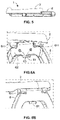
- FIG. 4 shows a perspective view of the device of FIG. 1 in its folded configuration
- FIG. 5 shows a lateral view of the device of FIG. 1 in the folded configuration
- FIGS. 6A and 6B show perspective views of an enlarged scale of a detail of the device of FIG. 1 (from front, and rear, respectively);
- FIGS. 7A and 7B show a locking mechanism of the device of FIG. 1 in two functional positions
- FIG. 8 shows an internal view of the locking mechanism of the device of FIG. 1 ;
- FIGS. 9A and 9B show inner views of the locking mechanism respectively shown in FIGS. 7A and 7B ;
- FIGS. 10A to 10C are views of an enlarged scale of a further locking mechanism in one of the legs of the device of FIG. 1 ;
- FIG. 11 shows further views of the device of FIG. 1 , with exemplary dimensions (in mm);
- FIG. 12 shows a perspective view of a device according to a second embodiment of the invention in its deployed (erect) configuration
- FIG. 13 shows an end view of the device according to the second embodiment in its deployed (erect) configuration
- FIG. 14 shows a side view of the device according to the second embodiment in its deployed (erect) configuration
- FIG. 15 shows a perspective view of the device according to the second embodiment in its folded configuration
- FIG. 16 shows a side view of the device according to the second embodiment in its folded configuration
- FIG. 17 shows the constituent parts of a locking mechanism employed in the device according to the second embodiment
- FIG. 18 shows a cutaway view of the locking mechanism employed in the device according to the second embodiment in a locked configuration
- FIG. 19 shows a sectional view of the locking mechanism employed in the device according to the second embodiment in the locked configuration
- FIG. 20 shows a cutaway view of the locking mechanism employed in the device according to the second embodiment in an unlocked configuration
- FIG. 21 shows a sectional view of the locking mechanism employed in the device according to the second embodiment in the unlocked configuration
- FIG. 22 shows a cutaway view of a part of a first end of a connecting element of the device according to the second embodiment when the locking mechanism is in the locked configuration
- FIG. 23 shows a cutaway view of the part of the first end of the connecting element of the device according to the second embodiment when the locking mechanism is in the unlocked configuration
- FIG. 24 shows a detail view of a portion of FIG. 23 .
- the toilet device 1 also referred to as a potty (or portable potty/travel potty), comprises a seat portion 2 which is a generally annular body having a profiled seating surface defining a central opening 3 .
- the seat portion 2 has a raised protuberance 4 defining the front of the toilet device 1 .
- the seat portion 2 is supported at opposite ends by a pair of leg portions 5 , 6 (side walls) of similar shape and substantially equal height.
- a first end of each leg portion is pivotally attached to its respective end.
- each leg portion has two feet portions 5 ′, 6 .
- the leg portions 5 , 6 are pivotally attached to the seat portion 2 such that they both fold towards the rear of the toilet device 1 as shown in FIGS. 4 and 5 .
- the pivotal attachment means is such that the leg portions 5 , 6 cannot fold in the opposite direction, towards the front of the toilet device 1 . It will be appreciated that this may be achieved in several ways, for example using ‘one-way’ hinges permitting unfolding in one direction only.
- the pivotal attachment means may include blocking elements to block the leg portions 5 , 6 from folding towards the front of the device.
- the leg portions 5 , 6 may be stopped by the profiling of the seat portion 2 itself.
- each leg portion 5 , 6 is pivotally attached to at least one connecting element 7 , 8 .
- the second end of one of the leg portions 5 , 6 is pivotally connected to a first end of the connecting element and the second end of the other leg portion is pivotally connected to a second end of the connecting element 7 , 8 .
- the feet portions 5 ′, 6 ′ are respectively pivotally connected by the connecting element, in this example two supporting beams 7 , 8 of substantially equal length.
- Each of the supporting beams 7 , 8 also referred to as braces, are located either end of the toilet device 1 (substantially parallel to the seat portion 1 ) and provide increased stability such that the toilet device does not wobble in the erect position.
- the feet portions 5 ′ of a leg portion may be additionally connected to each other by a further connecting element to increase stability.
- the leg portions 5 , 6 can have a D shape or be constructed as a single side wall In such configuration, one or more supporting beams can extend between the front and rear leg portions 5 , 6 , for example, with further supporting beam connecting the middle of the leg portions.
- the supporting beams 7 , 8 maintain the leg portions 5 , 6 parallel to each other at all times.
- the overall profile of the leg portions 5 , 6 and beams 7 , 8 arrangement can be regarded as a parallelogram, in both folded and unfolded (erect) positions, with the beams 7 , 8 being parallel to each other and the seat portion 2 .
- the supporting beams 7 , 8 are tucked to the either end of the seat portion 2 .
- the leg portions 5 , 6 and beams 7 , 8 arrangement increases the stability of the device 1 and allows the device to be unfolded in a quick manner.
- connecting the leg portions 5 , 6 allows them to unfold downwards in a synchronised manner, aided by gravity.
- the leg portions 5 , 6 are substantially parallel to each other so that the side profile of the toilet device 1 during the folding/unfolding operation is substantially a parallelogram.
- the side profile in use therefore may be regarded as a “collapsible parallelogram”.
- the leg portions 5 , 6 are secured in the folded position by a locking device or locking mechanism 60 included in the rear leg portion 6 .
- the locking mechanism 60 can be provided in the front leg portion 5 .
- the locking mechanism 60 has an operating element or button 61 which, when pressed, unlocks the rear leg portion 6 and gravity allows it to fall (connected to the front leg portion 5 ), away from the seat portion 2 , whilst the supporting beams maintain the relative distance between the front and rear feet portions 5 ′, 6 ′.
- FIGS. 7A to 9B A preferred embodiment of the locking mechanism 60 is now described with reference to FIGS. 7A to 9B .
- Pressing the button 61 upwards, towards the seat portion 2 of the device, causes at least one pivotable element 62 , to pivot around a fulcrum element 63 (a bolt).
- a fulcrum element 63 a bolt
- the bolt or pins 64 may have alternative orientations relative to the toilet seat portion 2 , for example they may be horizontal rather than vertical.
- the pins 61 protrude upwards from the rear leg 6 and engage with the seat portion 2 .
- the pins 61 can protrude in corresponding apertures (pin holes) 611 provided in the underside of the seat portion 2 .
- the button 61 is pressed, the pivotable elements 62 pivot around the bolts 63 causing the pins 62 to move downwards, retracting within the rear leg 6 . Accordingly, the pins are disengaged from the seat portion 2 , unlocking the rear leg portion 6 which fall downwards, towards the erect position.
- the rear and front leg portions 5 , 6 move together, being connected by beams 7 , 8 , forming a “collapsible parallelogram”.
- a user can quickly unfold the device 1 quickly, with one hand, by a flicking motion. After use, to fold back the device, the user can also unlock the rear leg portion 6 of the folded device 1 with one hand (holding the rear portion of the toilet device 1 and pressing the button 61 ). It is envisaged that the toilet device can be deployed in the unfolded (erect) position in a matter of seconds, preferably within 10 seconds, more preferably within 5 seconds.
- each of the pivotable elements 62 are biased by a torsion spring 65 (e.g. a metal spring) so that their ends engaging the button 61 (at the middle of the rear leg portion) are biased in a downward position and the pins 64 are biased upwards, as shown in FIG. 7A , FIG. 8 , FIG. 9A .
- a torsion spring 65 e.g. a metal spring
- the pins 64 can engage back with the underside of the seat portion, the locking mechanism 60 having a secondary latch for securing the toilet device 1 in the erect position and preventing it from collapsing
- the toilet device 1 can be unsecured from the erect position, by pressing button 61 and again, with one hand, the device can be folded very quickly with one hand into collapsed closed position).
- the pivotable elements 62 By pushing button 61 the pivotable elements 62 to swivel, retracting the pins 64 , therefore disengaging the rear leg portion 6 from the seat portion 2 .
- the leg portions 5 , 6 are folded back and the pins 64 engage back with the seat portion 2 , locking the toilet device in the folded position shown in FIG. 5 for example.
- a foot portion 6 ′ of the rear leg portion 6 has a rounded portion forming a hinge 70 connected to a connecting element 7 .
- the leg portion 6 ′ has aperture 80 for receiving a protrusion or detent element 85 provided in the hinge 70 .
- Protrusion or detent element 85 prevents gravity from allowing legs to drop thereby forcing rear upright leg portions 5 and 6 to be trapped behind the protrusion.
- the protrusion 85 is able to be flexed away therefore releasing rear upright and allowing gravity to allow the leg portions 5 , 6 to fall.
- the detent element 85 serves to increase stability of the toilet device 1 in its erect position, by securing the relative position of the beams 7 , 8 relative to the feet portions 5 ′, 6 ′.
- each of the four feet portions of the device is provided with detent locking means, although it will be appreciated that this is not essential.
- the device 100 includes a seat portion 102 , which is supported by a pair of leg portions 105 , 106 attached to opposite ends of the seat portion. A first end of each leg portion 105 , 106 is pivotally attached to its respective end of the seat portion 102 and the second end of each leg portion is connected to a connecting element 107 , whereby the device 100 can be moved between folded and unfolded (erect) positions like in the first embodiment.
- the construction of the leg portions of the second embodiment is different. Specifically, in FIG.
- one of the leg portions 105 , 106 is a side wall, and the other one of the leg portions comprises two leg components 109 extending from a transverse beam (not shown) in FIG. 12 .
- both leg portions 105 , 106 are sidewalls.
- the locking mechanism 110 of the device 100 of the second embodiment is also different with respect to the locking mechanism of the first embodiment. However, it will be noted that like the first embodiment the locking mechanism 110 is located at the rear of the device. In other words, when the leg portions 105 , 106 are flat and in the folded position the locking mechanism 110 is located at the end of the device to which the leg portions extend towards from the seat portion 102 .
- the locking mechanism 110 of the second embodiment is shown in greater detail in FIGS. 17 to 24 .
- the constituent parts of the locking mechanism of the second embodiment are shown in FIG. 17 .
- the locking mechanism 110 comprises a rear leg portion hub 116 provided on the leg portion located closest to the rear of the device 100 (the rear leg portion 106 ), coiled spring 118 , a locking plate 120 , a first end of the at least one connecting element 114 , a pin 124 and locking button 128 .
- the locking mechanism 110 is shown in the assembled state in a locked configuration.
- the at least one connecting element 107 is not permitted to pivot with respect to the rear leg portion 106 .
- the first end 114 of the connecting element 107 comprises an internal hub 132 .
- the internal hub 132 comprises an internal hub cylindrical portion 134 which projects from an internal wall 136 of the first end 114 of the connecting element 107 .
- the internal hub cylindrical portion 134 is located inside an inner cylindrical portion 138 of the rear leg portion hub 116 .
- the two cylindrical portions 134 , 138 are coupled to each other by way of the pin 124 and a washer 140 .
- the cylindrical portions 134 , 138 are located inside of a cylindrical passageway 142 provided in a ring portion 144 of the locking plate 120 .
- Lugs 122 project from the ring portion 114 of the locking plate 120 .
- the coiled spring 118 is arranged such that it urges the lug 122 into recesses 146 defined by the internal wall 136 .
- the locking mechanism 110 may be moved from the locked configuration to the unlocked configuration by pressing the locking button 126 .
- the locking mechanism 110 is shown in the unlocked configuration in FIGS. 20 and 21 .
- the locking button 126 comprises teeth 128 which are arranged to engage the locking plate 120 when the button 128 is pressed so as to urge the locking plate towards the coiled spring 118 such that the lugs 122 are expelled from the recesses 146 , thereby allowing the rear leg portion 106 to pivot with respect to the connecting element 107 .
- the teeth 128 are shown engaging the locking plate 120 in FIGS. 20 and 21 .
- the teeth 128 engage the locking plate 120 by passing through apertures 150 provided in the internal wall 136 . When the locking button 126 ceases to be pressed the teeth 128 ceased to engage the locking plate 120 and retreat backwards away from the locking plate 120 and coiled spring 118 .
- FIGS. 22 and 23 The apertures 150 in the internal wall 136 are shown in FIGS. 22 and 23 .
- the locking mechanism 110 is depicted in the locked configuration with the lugs 122 in the recesses 146 .
- FIG. 23 shows the lugs 122 not in the recesses 146 .
- the internal wall 136 has provided thereon a rib 162 .
- the rib 162 is arranged to engage with a groove 164 provided on an outer surface of an outer cylindrical portion 170 of the rear portion hub 116 , which surrounds the cylindrical portion 138 of the rear leg portion hub 116 .
- the rib 162 locates itself within the groove 164 .
- the rib 162 can only be removed from the groove 164 when the user applies sufficient force to the connecting element 107 and/or rear leg portion 106 .
- the rib 162 and groove 164 arrangement therefore prevent the device 100 from moving out of the folded position unintentionally.
- the rib 162 and groove 164 provide a “bump stop”.
- a plastic bag with handles may be placed in the opening 3 .
- the handles of the bag may be brought over the top of the seat portion 2 and attached to recess portions 7 a , 7 b , 8 a , 8 b of beams 7 , 8 labelled in FIG. 3 or tucked under the seat portion 2 .
- the recess portions span at least 50%, more preferably at least 80% of the height of the beams 7 , 8 , to secure a handle of the bag in place.
- the toilet device 1 may be pre-loaded with a bag, stored in the folded position and quickly deployed to the erect position as described above.
- the device of FIG. 12 may be used in a similar way with a plastic bag to that of the device of FIG. 1 .
- the toilet device 1 is usually made of a suitable material such as hard plastics, or any other suitable material.
- all components of the device 1 may be made from the same material, enabling the product to be recycled.
- the cover plate 63 ′ may need to be unscrewed and the metals removed.
- Exemplary dimensions (in mm) for a device usable as a potty for children toilet training are shown in FIG. 11 . It will be appreciated however that the dimensions of the device may vary and larger such portable toilet devices may be constructed for example, as suitable for adults in other use cases.
Abstract
Description
Claims (12)
Applications Claiming Priority (4)
| Application Number | Priority Date | Filing Date | Title |
|---|---|---|---|
| GB1810530.4 | 2018-06-27 | ||
| GBGB1810530.4A GB201810530D0 (en) | 2018-06-27 | 2018-06-27 | Toilet devices |
| GB1810530 | 2018-06-27 | ||
| PCT/GB2019/051827 WO2020002929A1 (en) | 2018-06-27 | 2019-06-27 | Toilet device |
Publications (2)
| Publication Number | Publication Date |
|---|---|
| US20210251439A1 US20210251439A1 (en) | 2021-08-19 |
| US11464372B2 true US11464372B2 (en) | 2022-10-11 |
Family
ID=63143658
Family Applications (1)
| Application Number | Title | Priority Date | Filing Date |
|---|---|---|---|
| US17/252,180 Active US11464372B2 (en) | 2018-06-27 | 2019-06-27 | Toilet device |
Country Status (5)
| Country | Link |
|---|---|
| US (1) | US11464372B2 (en) |
| EP (1) | EP3813620B1 (en) |
| CN (1) | CN112638221B (en) |
| GB (1) | GB201810530D0 (en) |
| WO (1) | WO2020002929A1 (en) |
Families Citing this family (1)
| Publication number | Priority date | Publication date | Assignee | Title |
|---|---|---|---|---|
| USD960334S1 (en) * | 2021-05-31 | 2022-08-09 | Danlin Pan | Travel potty |
Citations (12)
| Publication number | Priority date | Publication date | Assignee | Title |
|---|---|---|---|---|
| US2203076A (en) | 1939-03-17 | 1940-06-04 | Trimble Nurseryland Furniture | Infant's folding toilet seat |
| US3235884A (en) * | 1963-06-28 | 1966-02-22 | Rehsteiner Helene | Nursery chair |
| US3495277A (en) * | 1967-04-04 | 1970-02-17 | Herko Inc | Portable baby toilet training chair |
| US4052087A (en) * | 1976-11-22 | 1977-10-04 | Gagliardi Joseph A | Foldable caster chair for the handicapped |
| US4613994A (en) * | 1985-05-30 | 1986-09-30 | Oates Otto G | Collapsible portable enema seat |
| GB2184650A (en) | 1985-11-19 | 1987-07-01 | Geoffrey James Beer | Folding potty |
| US5161263A (en) * | 1991-05-07 | 1992-11-10 | Sassy, Inc. | Articulable training toilet apparatus |
| US6341386B1 (en) * | 1999-04-16 | 2002-01-29 | William A. Phillips | Portable potty apparatus |
| CN2910760Y (en) | 2006-07-07 | 2007-06-13 | 天津富士达自行车有限公司 | Folding casing used for folding bicycle |
| US20080005831A1 (en) | 2006-07-10 | 2008-01-10 | Seo Yong S | Handy Toilet Stool |
| GB2442198A (en) | 2006-09-29 | 2008-04-02 | Alan Frederick Sandy | Portable toilet seat/potty |
| US20150265109A1 (en) | 2014-03-21 | 2015-09-24 | Helen Of Troy Limited | Portable toilet device for a small child |
Family Cites Families (10)
| Publication number | Priority date | Publication date | Assignee | Title |
|---|---|---|---|---|
| US1163628A (en) * | 1915-02-18 | 1915-12-07 | William Henry Gibson | Child's seat. |
| US2679053A (en) * | 1950-10-19 | 1954-05-25 | Jr Dale P Smith | Infant's toilet seat |
| DE876587C (en) * | 1951-04-01 | 1953-05-15 | Berta Borack | Portable children's toilet |
| CN2059056U (en) * | 1989-09-29 | 1990-07-11 | 张胜利 | Folding chair for toilet |
| GB9707374D0 (en) * | 1997-04-11 | 1997-05-28 | Mangar International Ltd | Toilet aid for disabled and infirm persons |
| DE19839673C1 (en) * | 1998-09-01 | 1999-09-02 | Grammer Ag | Integral child seat for motor vehicle seat |
| WO2007085119A1 (en) * | 2006-01-26 | 2007-08-02 | Leung Cheung Siu | Portable closet |
| CN103405189B (en) * | 2013-09-05 | 2015-07-15 | 易欣 | Multipurpose children defecation device and children seat with overturning bracket |
| JP6645929B2 (en) * | 2016-08-01 | 2020-02-14 | アロン化成株式会社 | Portable toilet and leg rubber |
| CN107468137A (en) * | 2017-09-29 | 2017-12-15 | 中山市西区青原贸易代理服务部 | A kind of toilet seat for being easy to folding and carrying |
-
2018
- 2018-06-27 GB GBGB1810530.4A patent/GB201810530D0/en not_active Ceased
-
2019
- 2019-06-27 US US17/252,180 patent/US11464372B2/en active Active
- 2019-06-27 EP EP19736456.5A patent/EP3813620B1/en active Active
- 2019-06-27 WO PCT/GB2019/051827 patent/WO2020002929A1/en unknown
- 2019-06-27 CN CN201980043258.0A patent/CN112638221B/en active Active
Patent Citations (14)
| Publication number | Priority date | Publication date | Assignee | Title |
|---|---|---|---|---|
| US2203076A (en) | 1939-03-17 | 1940-06-04 | Trimble Nurseryland Furniture | Infant's folding toilet seat |
| US3235884A (en) * | 1963-06-28 | 1966-02-22 | Rehsteiner Helene | Nursery chair |
| US3495277A (en) * | 1967-04-04 | 1970-02-17 | Herko Inc | Portable baby toilet training chair |
| US4052087A (en) * | 1976-11-22 | 1977-10-04 | Gagliardi Joseph A | Foldable caster chair for the handicapped |
| US4613994A (en) * | 1985-05-30 | 1986-09-30 | Oates Otto G | Collapsible portable enema seat |
| GB2184650A (en) | 1985-11-19 | 1987-07-01 | Geoffrey James Beer | Folding potty |
| US5161263A (en) * | 1991-05-07 | 1992-11-10 | Sassy, Inc. | Articulable training toilet apparatus |
| US6341386B1 (en) * | 1999-04-16 | 2002-01-29 | William A. Phillips | Portable potty apparatus |
| CN2910760Y (en) | 2006-07-07 | 2007-06-13 | 天津富士达自行车有限公司 | Folding casing used for folding bicycle |
| US20080005831A1 (en) | 2006-07-10 | 2008-01-10 | Seo Yong S | Handy Toilet Stool |
| GB2442198A (en) | 2006-09-29 | 2008-04-02 | Alan Frederick Sandy | Portable toilet seat/potty |
| CN101516244A (en) | 2006-09-29 | 2009-08-26 | 艾伦·弗雷德里克·桑迪 | Toilet device |
| US20150265109A1 (en) | 2014-03-21 | 2015-09-24 | Helen Of Troy Limited | Portable toilet device for a small child |
| CN105979835A (en) | 2014-03-21 | 2016-09-28 | 特洛伊海伦有限公司 | Portable toilet device for a small child |
Non-Patent Citations (2)
| Title |
|---|
| Chinese Office Action for Application No. 201980043258.0, dated Nov. 19, 2021 (15 pages, including English translation). |
| International Search Report and Written Opinion on PCT Application No. PCT/GB2019/051827, dated Sep. 26, 2019 (13 pages). |
Also Published As
| Publication number | Publication date |
|---|---|
| EP3813620A1 (en) | 2021-05-05 |
| WO2020002929A1 (en) | 2020-01-02 |
| EP3813620B1 (en) | 2024-02-07 |
| CN112638221B (en) | 2022-08-09 |
| GB201810530D0 (en) | 2018-08-15 |
| CN112638221A (en) | 2021-04-09 |
| US20210251439A1 (en) | 2021-08-19 |
Similar Documents
| Publication | Publication Date | Title |
|---|---|---|
| US20220024508A1 (en) | Child stroller apparatus and child seat suitable for use on the same | |
| US8141895B2 (en) | Collapsible stroller and method of operating the same | |
| US4045045A (en) | Foldable child walker | |
| US6464242B2 (en) | Folding stroller | |
| US7334836B2 (en) | Foldable chair | |
| US10343704B2 (en) | Foldable stroller frame | |
| US10286940B2 (en) | Child stroller apparatus | |
| RU2643610C2 (en) | Frame with telescopic pushing handle for promenade or light perambulator and perambulator with such frame | |
| EP3095431A1 (en) | Double folding rollator | |
| GB2403898A (en) | Collapsible high chair for children | |
| JPS59106366A (en) | Baby car | |
| US20060237949A1 (en) | One hand release mechanism for stroller | |
| TWM550247U (en) | Cart easy to unfold and fix | |
| US6814368B2 (en) | Foldable stroller | |
| US11464372B2 (en) | Toilet device | |
| GB2386832A (en) | A foldable high chair | |
| CN108938339B (en) | Foldable walking aid | |
| WO2020029751A1 (en) | Baby stroller | |
| WO2020029456A1 (en) | Stroller | |
| WO2005080171A2 (en) | Push chair frame | |
| US7066099B2 (en) | Foldable article of furniture | |
| WO1999017707A1 (en) | Foldable walker with locking mechanism | |
| EP3624750A1 (en) | Foldable walker | |
| US20060107879A1 (en) | Foldable furniture device | |
| TWM286604U (en) | Foldable furniture featuring expandability and positionability |
Legal Events
| Date | Code | Title | Description |
|---|---|---|---|
| FEPP | Fee payment procedure |
Free format text: ENTITY STATUS SET TO UNDISCOUNTED (ORIGINAL EVENT CODE: BIG.); ENTITY STATUS OF PATENT OWNER: SMALL ENTITY |
|
| FEPP | Fee payment procedure |
Free format text: ENTITY STATUS SET TO SMALL (ORIGINAL EVENT CODE: SMAL); ENTITY STATUS OF PATENT OWNER: SMALL ENTITY |
|
| AS | Assignment |
Owner name: CONSTABLE GROUP LIMITED, UNITED KINGDOM Free format text: ASSIGNMENT OF ASSIGNORS INTEREST;ASSIGNOR:PERKINS, ANNE-MARIE;REEL/FRAME:055855/0889 Effective date: 20201222 |
|
| STPP | Information on status: patent application and granting procedure in general |
Free format text: APPLICATION DISPATCHED FROM PREEXAM, NOT YET DOCKETED |
|
| STPP | Information on status: patent application and granting procedure in general |
Free format text: DOCKETED NEW CASE - READY FOR EXAMINATION |
|
| STPP | Information on status: patent application and granting procedure in general |
Free format text: NON FINAL ACTION MAILED |
|
| STPP | Information on status: patent application and granting procedure in general |
Free format text: RESPONSE TO NON-FINAL OFFICE ACTION ENTERED AND FORWARDED TO EXAMINER |
|
| STPP | Information on status: patent application and granting procedure in general |
Free format text: NOTICE OF ALLOWANCE MAILED -- APPLICATION RECEIVED IN OFFICE OF PUBLICATIONS |
|
| STPP | Information on status: patent application and granting procedure in general |
Free format text: PUBLICATIONS -- ISSUE FEE PAYMENT RECEIVED |
|
| STPP | Information on status: patent application and granting procedure in general |
Free format text: PUBLICATIONS -- ISSUE FEE PAYMENT VERIFIED |
|
| STCF | Information on status: patent grant |
Free format text: PATENTED CASE |