US11462695B2 - Organic light emitting element - Google Patents
Organic light emitting element Download PDFInfo
- Publication number
- US11462695B2 US11462695B2 US16/495,087 US201816495087A US11462695B2 US 11462695 B2 US11462695 B2 US 11462695B2 US 201816495087 A US201816495087 A US 201816495087A US 11462695 B2 US11462695 B2 US 11462695B2
- Authority
- US
- United States
- Prior art keywords
- group
- substituted
- unsubstituted
- compound
- chemical formula
- Prior art date
- Legal status (The legal status is an assumption and is not a legal conclusion. Google has not performed a legal analysis and makes no representation as to the accuracy of the status listed.)
- Active, expires
Links
- 0 *C.CC.c1ccc2ncccc2c1 Chemical compound *C.CC.c1ccc2ncccc2c1 0.000 description 9
- KLSBNPSLEGBUSK-UHFFFAOYSA-N CCc1c2ccccc2c(C)c2ccccc12 Chemical compound CCc1c2ccccc2c(C)c2ccccc12 KLSBNPSLEGBUSK-UHFFFAOYSA-N 0.000 description 3
- XHPPLUYSNQCVFE-UHFFFAOYSA-N CC.CC.CC.CC.CCc1ccc2c(c1)C1(c3ccccc3O2)c2ccccc2-c2ccccc21.CCc1ccc2c(c1)Oc1ccccc1C21c2ccccc2-c2ccccc21.CCc1cccc2c1C1(c3ccccc3O2)c2ccccc2-c2ccccc21.CCc1cccc2c1Oc1ccccc1C21c2ccccc2-c2ccccc21 Chemical compound CC.CC.CC.CC.CCc1ccc2c(c1)C1(c3ccccc3O2)c2ccccc2-c2ccccc21.CCc1ccc2c(c1)Oc1ccccc1C21c2ccccc2-c2ccccc21.CCc1cccc2c1C1(c3ccccc3O2)c2ccccc2-c2ccccc21.CCc1cccc2c1Oc1ccccc1C21c2ccccc2-c2ccccc21 XHPPLUYSNQCVFE-UHFFFAOYSA-N 0.000 description 2
- OOVWBVSJFPNXHH-UHFFFAOYSA-N CC.CCC.c1ccc2c(c1)Oc1ccccc1C21c2ccccc2-c2ccccc21 Chemical compound CC.CCC.c1ccc2c(c1)Oc1ccccc1C21c2ccccc2-c2ccccc21 OOVWBVSJFPNXHH-UHFFFAOYSA-N 0.000 description 2
- HCKYWEUDLRWNKB-UHFFFAOYSA-N CC1=CC=C(C)C1.CC1=Nc2c(C)c(C)c(C)c(C)c2C1.Cc1c(C)c(C)c2c(cc3c4c(C)c(C)c(C)c(C)c4c4c(C)c(C)c(C)c(C)c4n32)c1C Chemical compound CC1=CC=C(C)C1.CC1=Nc2c(C)c(C)c(C)c(C)c2C1.Cc1c(C)c(C)c2c(cc3c4c(C)c(C)c(C)c(C)c4c4c(C)c(C)c(C)c(C)c4n32)c1C HCKYWEUDLRWNKB-UHFFFAOYSA-N 0.000 description 2
- PLEIKVRDHWKZHF-UHFFFAOYSA-N CC1=Nc2c(C)c(C)c(C)c(C)c2C1 Chemical compound CC1=Nc2c(C)c(C)c(C)c(C)c2C1 PLEIKVRDHWKZHF-UHFFFAOYSA-N 0.000 description 2
- TUTQONXOPMGQJT-UHFFFAOYSA-N Cc1c(C)c(C)c2c(c1C)Cc1c(C)c(C)c(C)c(C)c1N2C.Cc1cc(C)cc(C)c1.Cc1cc2c(C)c(C)c3cc(C)c(C)cc3c2cc1C.Cc1nc(C)c2c(C)c(C)c(C)c(C)c2c1C.Cc1nc(C)c2c(C)c(C)c(C)c(C)c2n1.Cc1nc2c(C)c(C)c(C)c(C)c2nc1C.Cc1nnc(C)c(C)c1C Chemical compound Cc1c(C)c(C)c2c(c1C)Cc1c(C)c(C)c(C)c(C)c1N2C.Cc1cc(C)cc(C)c1.Cc1cc2c(C)c(C)c3cc(C)c(C)cc3c2cc1C.Cc1nc(C)c2c(C)c(C)c(C)c(C)c2c1C.Cc1nc(C)c2c(C)c(C)c(C)c(C)c2n1.Cc1nc2c(C)c(C)c(C)c(C)c2nc1C.Cc1nnc(C)c(C)c1C TUTQONXOPMGQJT-UHFFFAOYSA-N 0.000 description 2
- SCNULLOICBOVJF-UHFFFAOYSA-N [C-]#[N+]c1ccccc1-c1ccc(-c2nc(-c3ccccc3)nc(-c3cccc4c3Oc3ccccc3C43c4ccccc4-c4ccccc43)n2)cc1.c1ccc(-c2nc(-c3ccc(-c4ccc5c(c4)C4(c6ccccc6O5)c5ccccc5-c5ccccc54)cc3)nc(-c3ccc(-n4c5ccccc5c5ccccc54)cc3)n2)cc1.c1ccc(-c2nc(-c3ccc(-c4ccc5c6ccccc6c6ccccc6c5c4)cc3)nc(-c3cccc4c3Oc3ccccc3C43c4ccccc4-c4ccccc43)n2)cc1.c1ccc(-c2nc(-c3ccc(-c4cccc5cccnc45)cc3)nc(-c3cccc(-c4ccc5c(c4)C4(c6ccccc6O5)c5ccccc5-c5ccccc54)c3)n2)cc1 Chemical compound [C-]#[N+]c1ccccc1-c1ccc(-c2nc(-c3ccccc3)nc(-c3cccc4c3Oc3ccccc3C43c4ccccc4-c4ccccc43)n2)cc1.c1ccc(-c2nc(-c3ccc(-c4ccc5c(c4)C4(c6ccccc6O5)c5ccccc5-c5ccccc54)cc3)nc(-c3ccc(-n4c5ccccc5c5ccccc54)cc3)n2)cc1.c1ccc(-c2nc(-c3ccc(-c4ccc5c6ccccc6c6ccccc6c5c4)cc3)nc(-c3cccc4c3Oc3ccccc3C43c4ccccc4-c4ccccc43)n2)cc1.c1ccc(-c2nc(-c3ccc(-c4cccc5cccnc45)cc3)nc(-c3cccc(-c4ccc5c(c4)C4(c6ccccc6O5)c5ccccc5-c5ccccc54)c3)n2)cc1 SCNULLOICBOVJF-UHFFFAOYSA-N 0.000 description 2
- ZNHUNSQDJPCAKM-UHFFFAOYSA-N c1cc(-c2ccc3ccccc3c2)cc(-c2c3ccccc3c(-c3cccc4ccccc34)c3ccccc23)c1.c1ccc2c(-c3ccc(-c4c5ccccc5c(-c5cccc6ccccc56)c5ccccc45)cc3)cccc2c1.c1ccc2cc(-c3ccc(-c4c5ccccc5c(-c5cccc6ccccc56)c5ccccc45)cc3)ccc2c1 Chemical compound c1cc(-c2ccc3ccccc3c2)cc(-c2c3ccccc3c(-c3cccc4ccccc34)c3ccccc23)c1.c1ccc2c(-c3ccc(-c4c5ccccc5c(-c5cccc6ccccc56)c5ccccc45)cc3)cccc2c1.c1ccc2cc(-c3ccc(-c4c5ccccc5c(-c5cccc6ccccc56)c5ccccc45)cc3)ccc2c1 ZNHUNSQDJPCAKM-UHFFFAOYSA-N 0.000 description 2
- BHVXPWGWMWLOEK-UHFFFAOYSA-N c1cc(-c2cccc3ccccc23)cc(-c2c3ccccc3c(-c3cccc4ccccc34)c3ccccc23)c1.c1ccc(-c2ccc(-c3c4ccccc4c(-c4ccc(-c5ccccc5)c5ccccc45)c4ccccc34)cc2)cc1.c1ccc(-c2ccc(-c3c4ccccc4c(-c4cccc5ccccc45)c4ccccc34)c3ccccc23)cc1.c1ccc(-c2ccc(-c3c4ccccc4c(-c4ccccc4)c4ccccc34)c3ccccc23)cc1 Chemical compound c1cc(-c2cccc3ccccc23)cc(-c2c3ccccc3c(-c3cccc4ccccc34)c3ccccc23)c1.c1ccc(-c2ccc(-c3c4ccccc4c(-c4ccc(-c5ccccc5)c5ccccc45)c4ccccc34)cc2)cc1.c1ccc(-c2ccc(-c3c4ccccc4c(-c4cccc5ccccc45)c4ccccc34)c3ccccc23)cc1.c1ccc(-c2ccc(-c3c4ccccc4c(-c4ccccc4)c4ccccc34)c3ccccc23)cc1 BHVXPWGWMWLOEK-UHFFFAOYSA-N 0.000 description 2
- UVRWHCAQFWSHQQ-UHFFFAOYSA-N c1ccc(-c2cc(-c3c4ccccc4c(-c4cccc5ccccc45)c4ccccc34)c3ccccc3c2)cc1.c1ccc(-c2cc(-c3c4ccccc4c(-c4ccccc4)c4ccccc34)c3ccccc3c2)cc1.c1ccc(-c2ccc(-c3c4ccccc4c(-c4ccc(-c5ccccc5)c5ccccc45)c4ccccc34)cc2)cc1 Chemical compound c1ccc(-c2cc(-c3c4ccccc4c(-c4cccc5ccccc45)c4ccccc34)c3ccccc3c2)cc1.c1ccc(-c2cc(-c3c4ccccc4c(-c4ccccc4)c4ccccc34)c3ccccc3c2)cc1.c1ccc(-c2ccc(-c3c4ccccc4c(-c4ccc(-c5ccccc5)c5ccccc45)c4ccccc34)cc2)cc1 UVRWHCAQFWSHQQ-UHFFFAOYSA-N 0.000 description 2
- BKSQSPHQCCSGRK-UHFFFAOYSA-N c1ccc(-c2cc(-c3ccccc3)cc(-c3c4ccccc4c(-c4cccc5ccccc45)c4ccccc34)c2)cc1.c1ccc(-c2ccc(-c3c4ccccc4c(-c4cc(-c5ccccc5)cc5ccccc45)c4ccccc34)cc2)cc1.c1ccc(-c2ccc(-c3ccc(-c4c5ccccc5c(-c5cccc6ccccc56)c5ccccc45)cc3)cc2)cc1 Chemical compound c1ccc(-c2cc(-c3ccccc3)cc(-c3c4ccccc4c(-c4cccc5ccccc45)c4ccccc34)c2)cc1.c1ccc(-c2ccc(-c3c4ccccc4c(-c4cc(-c5ccccc5)cc5ccccc45)c4ccccc34)cc2)cc1.c1ccc(-c2ccc(-c3ccc(-c4c5ccccc5c(-c5cccc6ccccc56)c5ccccc45)cc3)cc2)cc1 BKSQSPHQCCSGRK-UHFFFAOYSA-N 0.000 description 2
- GCIROIYNKOKSQG-UHFFFAOYSA-N c1ccc(-c2cc(-c3ccccc3)nc(-c3ccc(-c4ccccc4-c4cccc5c4Oc4ccccc4C54c5ccccc5-c5ccccc54)cc3)n2)cc1.c1ccc(-c2cc(-c3ccccc3)nc(-c3ccccc3-c3ccc(-c4cccc5c4Oc4ccccc4C54c5ccccc5-c5ccccc54)cc3)n2)cc1.c1ccc(-c2ccc(-c3cc(-c4ccccc4)nc(-c4cccc(-c5cccc(-c6cccc7c6Oc6ccccc6C76c7ccccc7-c7ccccc76)c5)c4)n3)cc2)cc1.c1ccc(-c2cccc(-c3cc(-c4ccccc4)nc(-c4cccc(-c5cccc(-c6cccc7c6Oc6ccccc6C76c7ccccc7-c7ccccc76)c5)c4)n3)c2)cc1 Chemical compound c1ccc(-c2cc(-c3ccccc3)nc(-c3ccc(-c4ccccc4-c4cccc5c4Oc4ccccc4C54c5ccccc5-c5ccccc54)cc3)n2)cc1.c1ccc(-c2cc(-c3ccccc3)nc(-c3ccccc3-c3ccc(-c4cccc5c4Oc4ccccc4C54c5ccccc5-c5ccccc54)cc3)n2)cc1.c1ccc(-c2ccc(-c3cc(-c4ccccc4)nc(-c4cccc(-c5cccc(-c6cccc7c6Oc6ccccc6C76c7ccccc7-c7ccccc76)c5)c4)n3)cc2)cc1.c1ccc(-c2cccc(-c3cc(-c4ccccc4)nc(-c4cccc(-c5cccc(-c6cccc7c6Oc6ccccc6C76c7ccccc7-c7ccccc76)c5)c4)n3)c2)cc1 GCIROIYNKOKSQG-UHFFFAOYSA-N 0.000 description 2
- MXJKIWBHUXNIMI-UHFFFAOYSA-N c1ccc(-c2cc(-c3ccccc3)nc(-c3cccc(-c4ccc(-c5cccc6c5Oc5ccccc5C65c6ccccc6-c6ccccc65)cc4)c3)n2)cc1.c1ccc(-c2cc(-c3ccccc3)nc(-c3cccc(-c4ccccc4-c4cccc5c4Oc4ccccc4C54c5ccccc5-c5ccccc54)c3)n2)cc1.c1ccc(-c2cc(-c3ccccc3)nc(-c3ccccc3-c3ccccc3-c3cccc4c3Oc3ccccc3C43c4ccccc4-c4ccccc43)n2)cc1 Chemical compound c1ccc(-c2cc(-c3ccccc3)nc(-c3cccc(-c4ccc(-c5cccc6c5Oc5ccccc5C65c6ccccc6-c6ccccc65)cc4)c3)n2)cc1.c1ccc(-c2cc(-c3ccccc3)nc(-c3cccc(-c4ccccc4-c4cccc5c4Oc4ccccc4C54c5ccccc5-c5ccccc54)c3)n2)cc1.c1ccc(-c2cc(-c3ccccc3)nc(-c3ccccc3-c3ccccc3-c3cccc4c3Oc3ccccc3C43c4ccccc4-c4ccccc43)n2)cc1 MXJKIWBHUXNIMI-UHFFFAOYSA-N 0.000 description 2
- OCHLZNISOZYFPP-UHFFFAOYSA-N c1ccc(-c2ccc(-c3c4ccccc4c(-c4ccc5ccccc5c4)c4ccccc34)cc2)cc1.c1ccc(-c2ccc(-c3c4ccccc4c(-c4cccc5ccccc45)c4ccccc34)cc2)cc1.c1ccc(-c2cccc(-c3c4ccccc4c(-c4ccc5ccccc5c4)c4ccccc34)c2)cc1.c1ccc(-c2cccc(-c3c4ccccc4c(-c4cccc5ccccc45)c4ccccc34)c2)cc1 Chemical compound c1ccc(-c2ccc(-c3c4ccccc4c(-c4ccc5ccccc5c4)c4ccccc34)cc2)cc1.c1ccc(-c2ccc(-c3c4ccccc4c(-c4cccc5ccccc45)c4ccccc34)cc2)cc1.c1ccc(-c2cccc(-c3c4ccccc4c(-c4ccc5ccccc5c4)c4ccccc34)c2)cc1.c1ccc(-c2cccc(-c3c4ccccc4c(-c4cccc5ccccc45)c4ccccc34)c2)cc1 OCHLZNISOZYFPP-UHFFFAOYSA-N 0.000 description 2
- NRNKIHQGRHOFEX-UHFFFAOYSA-N c1ccc(-c2ccc(-c3c4ccccc4c(-c4cccc5ccccc45)c4ccccc34)cc2-c2ccccc2)cc1.c1ccc(-c2cccc3cc(-c4c5ccccc5c(-c5ccccc5)c5ccccc45)ccc23)cc1 Chemical compound c1ccc(-c2ccc(-c3c4ccccc4c(-c4cccc5ccccc45)c4ccccc34)cc2-c2ccccc2)cc1.c1ccc(-c2cccc3cc(-c4c5ccccc5c(-c5ccccc5)c5ccccc45)ccc23)cc1 NRNKIHQGRHOFEX-UHFFFAOYSA-N 0.000 description 2
- OHNKROGITMADIQ-UHFFFAOYSA-N c1ccc(-c2ccc(-c3nc(-c4ccccc4)nc(-c4ccc(-c5cccc6c5C5(c7ccccc7O6)c6ccccc6-c6ccccc65)cc4)n3)cc2)cc1.c1ccc(-c2nc(-c3ccc(-c4cccc5c4Oc4ccccc4C54c5ccccc5-c5ccccc54)cc3)nc(-c3ccc4c5ccccc5c5ccccc5c4c3)n2)cc1.c1ccc(-c2nc(-c3ccc(-c4cccc5c4oc4ccccc45)cc3)nc(-c3cccc4c3C3(c5ccccc5O4)c4ccccc4-c4ccccc43)n2)cc1.c1ccc(-c2nc(-c3ccccc3)nc(-c3cccc4c3C3(c5ccccc5O4)c4ccccc4-c4ccccc43)n2)cc1 Chemical compound c1ccc(-c2ccc(-c3nc(-c4ccccc4)nc(-c4ccc(-c5cccc6c5C5(c7ccccc7O6)c6ccccc6-c6ccccc65)cc4)n3)cc2)cc1.c1ccc(-c2nc(-c3ccc(-c4cccc5c4Oc4ccccc4C54c5ccccc5-c5ccccc54)cc3)nc(-c3ccc4c5ccccc5c5ccccc5c4c3)n2)cc1.c1ccc(-c2nc(-c3ccc(-c4cccc5c4oc4ccccc45)cc3)nc(-c3cccc4c3C3(c5ccccc5O4)c4ccccc4-c4ccccc43)n2)cc1.c1ccc(-c2nc(-c3ccccc3)nc(-c3cccc4c3C3(c5ccccc5O4)c4ccccc4-c4ccccc43)n2)cc1 OHNKROGITMADIQ-UHFFFAOYSA-N 0.000 description 2
- QMZMFFRWGYVECQ-UHFFFAOYSA-N c1ccc(-c2ccc3cc(-c4c5ccccc5c(-c5ccc6ccccc6c5)c5ccccc45)ccc3c2)cc1.c1ccc(-c2ccc3cc(-c4c5ccccc5c(-c5cccc6ccccc56)c5ccccc45)ccc3c2)cc1.c1ccc(-c2cccc(-c3ccc(-c4c5ccccc5c(-c5cccc6ccccc56)c5ccccc45)cc3)c2)cc1 Chemical compound c1ccc(-c2ccc3cc(-c4c5ccccc5c(-c5ccc6ccccc6c5)c5ccccc45)ccc3c2)cc1.c1ccc(-c2ccc3cc(-c4c5ccccc5c(-c5cccc6ccccc56)c5ccccc45)ccc3c2)cc1.c1ccc(-c2cccc(-c3ccc(-c4c5ccccc5c(-c5cccc6ccccc56)c5ccccc45)cc3)c2)cc1 QMZMFFRWGYVECQ-UHFFFAOYSA-N 0.000 description 2
- ZWRGYULQWVIQHL-UHFFFAOYSA-N c1ccc(-c2ccc3cc(-c4c5ccccc5c(-c5ccccc5)c5ccccc45)ccc3c2)cc1.c1ccc(-c2cccc(-c3c4ccccc4c(-c4cc(-c5ccccc5)cc5ccccc45)c4ccccc34)c2)cc1.c1ccc2cc(-c3ccc(-c4c5ccccc5c(-c5ccc6ccccc6c5)c5ccccc45)cc3)ccc2c1 Chemical compound c1ccc(-c2ccc3cc(-c4c5ccccc5c(-c5ccccc5)c5ccccc45)ccc3c2)cc1.c1ccc(-c2cccc(-c3c4ccccc4c(-c4cc(-c5ccccc5)cc5ccccc45)c4ccccc34)c2)cc1.c1ccc2cc(-c3ccc(-c4c5ccccc5c(-c5ccc6ccccc6c5)c5ccccc45)cc3)ccc2c1 ZWRGYULQWVIQHL-UHFFFAOYSA-N 0.000 description 2
- SFOYPZGJEFUUTH-UHFFFAOYSA-N c1ccc(-c2ccc3cccc(-c4cccc5c4Oc4ccccc4C54c5ccccc5-c5ccccc54)c3n2)cc1.c1ccc(-c2nnc(-c3cccc4c3Oc3ccccc3C43c4ccccc4-c4ccccc43)s2)cc1.c1ccc2c(c1)Oc1c(-c3ccc(-c4cccc5ccccc45)nn3)cccc1C21c2ccccc2-c2ccccc21.c1ccc2c(c1)Oc1c(-c3ccc4c5ccccc5n5c6ccccc6nc5c4c3)cccc1C21c2ccccc2-c2ccccc21.c1ccc2c(c1)Oc1c(-c3nc(-c4cccc5ccccc45)c4ccccc4n3)cccc1C21c2ccccc2-c2ccccc21 Chemical compound c1ccc(-c2ccc3cccc(-c4cccc5c4Oc4ccccc4C54c5ccccc5-c5ccccc54)c3n2)cc1.c1ccc(-c2nnc(-c3cccc4c3Oc3ccccc3C43c4ccccc4-c4ccccc43)s2)cc1.c1ccc2c(c1)Oc1c(-c3ccc(-c4cccc5ccccc45)nn3)cccc1C21c2ccccc2-c2ccccc21.c1ccc2c(c1)Oc1c(-c3ccc4c5ccccc5n5c6ccccc6nc5c4c3)cccc1C21c2ccccc2-c2ccccc21.c1ccc2c(c1)Oc1c(-c3nc(-c4cccc5ccccc45)c4ccccc4n3)cccc1C21c2ccccc2-c2ccccc21 SFOYPZGJEFUUTH-UHFFFAOYSA-N 0.000 description 2
- GQMYSPIPEVBHJN-UHFFFAOYSA-N c1ccc(-c2nc(-c3ccc(-c4ccc(-n5c6ccccc6c6ccccc65)cc4)cc3)cc(-c3ccc4c(c3)C3(c5ccccc5O4)c4ccccc4-c4ccccc43)n2)cc1.c1ccc(-c2nc(-c3ccc(-c4ccc5c6ccccc6c6ccccc6c5c4)cc3)nc(-c3cccc4c3C3(c5ccccc5O4)c4ccccc4-c4ccccc43)n2)cc1.c1ccc(-c2nc(-c3ccc(-n4c5ccccc5c5ccccc54)cc3)cc(-c3ccc4c(c3)C3(c5ccccc5O4)c4ccccc4-c4ccccc43)n2)cc1.c1ccc(-c2nc(-c3ccccc3)nc(-c3cccc(-c4cccc5c4C4(c6ccccc6O5)c5ccccc5-c5ccccc54)c3)n2)cc1 Chemical compound c1ccc(-c2nc(-c3ccc(-c4ccc(-n5c6ccccc6c6ccccc65)cc4)cc3)cc(-c3ccc4c(c3)C3(c5ccccc5O4)c4ccccc4-c4ccccc43)n2)cc1.c1ccc(-c2nc(-c3ccc(-c4ccc5c6ccccc6c6ccccc6c5c4)cc3)nc(-c3cccc4c3C3(c5ccccc5O4)c4ccccc4-c4ccccc43)n2)cc1.c1ccc(-c2nc(-c3ccc(-n4c5ccccc5c5ccccc54)cc3)cc(-c3ccc4c(c3)C3(c5ccccc5O4)c4ccccc4-c4ccccc43)n2)cc1.c1ccc(-c2nc(-c3ccccc3)nc(-c3cccc(-c4cccc5c4C4(c6ccccc6O5)c5ccccc5-c5ccccc54)c3)n2)cc1 GQMYSPIPEVBHJN-UHFFFAOYSA-N 0.000 description 2
- GCHDETZMBIVUEG-UHFFFAOYSA-N Brc1cc(-c2ccccc2)cc(-c2ccccc2)n1.CC1(C)OB(c2ccc3c(c2)C2(c4ccccc4O3)c3ccccc3-c3ccccc32)OC1(C)C.c1ccc(-c2cc(-c3ccccc3)nc(-c3ccc4c(c3)C3(c5ccccc5O4)c4ccccc4-c4ccccc43)c2)cc1 Chemical compound Brc1cc(-c2ccccc2)cc(-c2ccccc2)n1.CC1(C)OB(c2ccc3c(c2)C2(c4ccccc4O3)c3ccccc3-c3ccccc32)OC1(C)C.c1ccc(-c2cc(-c3ccccc3)nc(-c3ccc4c(c3)C3(c5ccccc5O4)c4ccccc4-c4ccccc43)c2)cc1 GCHDETZMBIVUEG-UHFFFAOYSA-N 0.000 description 1
- VHFJDJJDKWHIHD-UHFFFAOYSA-N Brc1ccc(-c2nc3ccccc3n2-c2ccccc2)cc1.CC1(C)OB(c2ccc3c(c2)Oc2ccccc2C32c3ccccc3-c3ccccc32)OC1(C)C.c1ccc(-n2c(-c3ccc(-c4ccc5c(c4)Oc4ccccc4C54c5ccccc5-c5ccccc54)cc3)nc3ccccc32)cc1 Chemical compound Brc1ccc(-c2nc3ccccc3n2-c2ccccc2)cc1.CC1(C)OB(c2ccc3c(c2)Oc2ccccc2C32c3ccccc3-c3ccccc32)OC1(C)C.c1ccc(-n2c(-c3ccc(-c4ccc5c(c4)Oc4ccccc4C54c5ccccc5-c5ccccc54)cc3)nc3ccccc32)cc1 VHFJDJJDKWHIHD-UHFFFAOYSA-N 0.000 description 1
- NRMCSFJZGVVEEH-UHFFFAOYSA-N Brc1ccc2ccc3cccnc3c2n1.CC1(C)OB(c2cccc3c2Oc2ccccc2C32c3ccccc3-c3ccccc32)OC1(C)C.c1ccc2c(c1)Oc1c(-c3ccc4ccc5cccnc5c4n3)cccc1C21c2ccccc2-c2ccccc21 Chemical compound Brc1ccc2ccc3cccnc3c2n1.CC1(C)OB(c2cccc3c2Oc2ccccc2C32c3ccccc3-c3ccccc32)OC1(C)C.c1ccc2c(c1)Oc1c(-c3ccc4ccc5cccnc5c4n3)cccc1C21c2ccccc2-c2ccccc21 NRMCSFJZGVVEEH-UHFFFAOYSA-N 0.000 description 1
- DMGQLDZARSEGLX-UHFFFAOYSA-N Brc1cccc(-c2nc(-c3ccccc3)nc(-c3ccccc3)n2)c1.CC1(C)OB(c2ccc3c(c2)C2(c4ccccc4O3)c3ccccc3-c3ccccc32)OC1(C)C.c1ccc(-c2nc(-c3ccccc3)nc(-c3cccc(-c4ccc5c(c4)C4(c6ccccc6O5)c5ccccc5-c5ccccc54)c3)n2)cc1 Chemical compound Brc1cccc(-c2nc(-c3ccccc3)nc(-c3ccccc3)n2)c1.CC1(C)OB(c2ccc3c(c2)C2(c4ccccc4O3)c3ccccc3-c3ccccc32)OC1(C)C.c1ccc(-c2nc(-c3ccccc3)nc(-c3cccc(-c4ccc5c(c4)C4(c6ccccc6O5)c5ccccc5-c5ccccc54)c3)n2)cc1 DMGQLDZARSEGLX-UHFFFAOYSA-N 0.000 description 1
- BZBCHMZCOYPURB-UHFFFAOYSA-N Brc1cccc2ccc(-c3ccccc3)nc12.CC1(C)OB(c2ccc3c(c2)C2(c4ccccc4O3)c3ccccc3-c3ccccc32)OC1(C)C.c1ccc(-c2ccc3cccc(-c4ccc5c(c4)C4(c6ccccc6O5)c5ccccc5-c5ccccc54)c3n2)cc1 Chemical compound Brc1cccc2ccc(-c3ccccc3)nc12.CC1(C)OB(c2ccc3c(c2)C2(c4ccccc4O3)c3ccccc3-c3ccccc32)OC1(C)C.c1ccc(-c2ccc3cccc(-c4ccc5c(c4)C4(c6ccccc6O5)c5ccccc5-c5ccccc54)c3n2)cc1 BZBCHMZCOYPURB-UHFFFAOYSA-N 0.000 description 1
- JHCKMOAIFKCOMO-UHFFFAOYSA-N Brc1cccc2cnccc12.CC1(C)OB(c2ccc3c(c2)C2(c4ccccc4O3)c3ccccc3-c3ccccc32)OC1(C)C.c1ccc2c(c1)Oc1ccc(-c3cccc4cnccc34)cc1C21c2ccccc2-c2ccccc21 Chemical compound Brc1cccc2cnccc12.CC1(C)OB(c2ccc3c(c2)C2(c4ccccc4O3)c3ccccc3-c3ccccc32)OC1(C)C.c1ccc2c(c1)Oc1ccc(-c3cccc4cnccc34)cc1C21c2ccccc2-c2ccccc21 JHCKMOAIFKCOMO-UHFFFAOYSA-N 0.000 description 1
- ZOZCVZZDPIBUOJ-UHFFFAOYSA-N C.CC.CCC.c1ccc2c(c1)Oc1ccccc1C21c2ccccc2-c2ccccc21 Chemical compound C.CC.CCC.c1ccc2c(c1)Oc1ccccc1C21c2ccccc2-c2ccccc21 ZOZCVZZDPIBUOJ-UHFFFAOYSA-N 0.000 description 1
- YDOIJOIKIYULLB-UHFFFAOYSA-N C1=CC2=CC(c3nc(-c4ccccc4)nc(-c4ccc(-c5ccc6c(c5)Oc5ccccc5C65c6ccccc6-c6ccccc65)cc4)n3)=CC3C=CCC(=C1)C23.c1ccc(-c2cccc(-c3nc(-c4ccc(-c5ccc6c(c5)Oc5ccccc5C65c6ccccc6-c6ccccc65)cc4)nc(-c4cccc(-c5ccccc5)c4)n3)c2)cc1.c1ccc(-c2nc(-c3ccc(-c4ccc5c(c4)Oc4ccccc4C54c5ccccc5-c5ccccc54)cc3)nc(-c3ccc4c(ccc5ccccc54)c3)n2)cc1 Chemical compound C1=CC2=CC(c3nc(-c4ccccc4)nc(-c4ccc(-c5ccc6c(c5)Oc5ccccc5C65c6ccccc6-c6ccccc65)cc4)n3)=CC3C=CCC(=C1)C23.c1ccc(-c2cccc(-c3nc(-c4ccc(-c5ccc6c(c5)Oc5ccccc5C65c6ccccc6-c6ccccc65)cc4)nc(-c4cccc(-c5ccccc5)c4)n3)c2)cc1.c1ccc(-c2nc(-c3ccc(-c4ccc5c(c4)Oc4ccccc4C54c5ccccc5-c5ccccc54)cc3)nc(-c3ccc4c(ccc5ccccc54)c3)n2)cc1 YDOIJOIKIYULLB-UHFFFAOYSA-N 0.000 description 1
- VMLJUAMVBAKSMQ-UHFFFAOYSA-N C1=CCC(c2cc(-c3ccc(-c4ccc(-c5ccc6c(c5)C5(c7ccccc7O6)c6ccccc6-c6ccccc65)cc4)cc3)nc(-c3ccccc3)n2)C=C1.c1ccc(-c2cc(-c3c(-c4ccc5c(c4)C4(c6ccccc6O5)c5ccccc5-c5ccccc54)ccc4ccccc34)nc(-c3ccccc3)n2)cc1.c1ccc(-c2cc(-c3ccc(-c4ccc5c(c4)C4(c6ccccc6O5)c5ccccc5-c5ccccc54)nc3)nc(-c3ccccc3)n2)cc1.c1ccc(-c2cc(-c3ccc(-c4ccc5c(c4)C4(c6ccccc6O5)c5ccccc5-c5ccccc54)o3)nc(-c3ccccc3)n2)cc1.c1ccc(-c2cc(-c3ccc(-c4ccc5c(c4)C4(c6ccccc6O5)c5ccccc5-c5ccccc54)s3)nc(-c3ccccc3)n2)cc1.c1ccc(-c2cc(-c3cccc(-c4ccc5c(c4)C4(c6ccccc6O5)c5ccccc5-c5ccccc54)n3)nc(-c3ccccc3)n2)cc1.c1ccc(-c2cc(-c3cccnc3-c3ccc4c(c3)C3(c5ccccc5O4)c4ccccc4-c4ccccc43)nc(-c3ccccc3)n2)cc1.c1ccc(-c2nc(-c3cccc(-c4cccc(-c5ccc6c(c5)C5(c7ccccc7O6)c6ccccc6-c6ccccc65)c4)c3)cc(-c3ccccc3-c3ccccc3)n2)cc1 Chemical compound C1=CCC(c2cc(-c3ccc(-c4ccc(-c5ccc6c(c5)C5(c7ccccc7O6)c6ccccc6-c6ccccc65)cc4)cc3)nc(-c3ccccc3)n2)C=C1.c1ccc(-c2cc(-c3c(-c4ccc5c(c4)C4(c6ccccc6O5)c5ccccc5-c5ccccc54)ccc4ccccc34)nc(-c3ccccc3)n2)cc1.c1ccc(-c2cc(-c3ccc(-c4ccc5c(c4)C4(c6ccccc6O5)c5ccccc5-c5ccccc54)nc3)nc(-c3ccccc3)n2)cc1.c1ccc(-c2cc(-c3ccc(-c4ccc5c(c4)C4(c6ccccc6O5)c5ccccc5-c5ccccc54)o3)nc(-c3ccccc3)n2)cc1.c1ccc(-c2cc(-c3ccc(-c4ccc5c(c4)C4(c6ccccc6O5)c5ccccc5-c5ccccc54)s3)nc(-c3ccccc3)n2)cc1.c1ccc(-c2cc(-c3cccc(-c4ccc5c(c4)C4(c6ccccc6O5)c5ccccc5-c5ccccc54)n3)nc(-c3ccccc3)n2)cc1.c1ccc(-c2cc(-c3cccnc3-c3ccc4c(c3)C3(c5ccccc5O4)c4ccccc4-c4ccccc43)nc(-c3ccccc3)n2)cc1.c1ccc(-c2nc(-c3cccc(-c4cccc(-c5ccc6c(c5)C5(c7ccccc7O6)c6ccccc6-c6ccccc65)c4)c3)cc(-c3ccccc3-c3ccccc3)n2)cc1 VMLJUAMVBAKSMQ-UHFFFAOYSA-N 0.000 description 1
- JWUFKEPESYTNKF-UHFFFAOYSA-N C1=CCC(c2nc(-c3ccccc3)nc(-c3ccc(-c4ccc(-c5ccc6c(c5)C5(c7ccccc7O6)c6ccccc6-c6ccccc65)cc4)cc3)n2)C=C1.c1ccc(-c2ccc(-c3nc(-c4ccccc4)nc(-c4cccc(-c5cccc(-c6ccc7c(c6)C6(c8ccccc8O7)c7ccccc7-c7ccccc76)c5)c4)n3)cc2)cc1.c1ccc(-c2cccc(-c3nc(-c4ccccc4)nc(-c4cccc(-c5cccc(-c6ccc7c(c6)C6(c8ccccc8O7)c7ccccc7-c7ccccc76)c5)c4)n3)c2)cc1.c1ccc(-c2nc(-c3ccccc3)nc(-c3c(-c4ccc5c(c4)C4(c6ccccc6O5)c5ccccc5-c5ccccc54)ccc4ccccc34)n2)cc1.c1ccc(-c2nc(-c3ccccc3)nc(-c3ccc(-c4ccc5c(c4)C4(c6ccccc6O5)c5ccccc5-c5ccccc54)o3)n2)cc1.c1ccc(-c2nc(-c3ccccc3)nc(-c3ccc(-c4ccc5c(c4)C4(c6ccccc6O5)c5ccccc5-c5ccccc54)s3)n2)cc1 Chemical compound C1=CCC(c2nc(-c3ccccc3)nc(-c3ccc(-c4ccc(-c5ccc6c(c5)C5(c7ccccc7O6)c6ccccc6-c6ccccc65)cc4)cc3)n2)C=C1.c1ccc(-c2ccc(-c3nc(-c4ccccc4)nc(-c4cccc(-c5cccc(-c6ccc7c(c6)C6(c8ccccc8O7)c7ccccc7-c7ccccc76)c5)c4)n3)cc2)cc1.c1ccc(-c2cccc(-c3nc(-c4ccccc4)nc(-c4cccc(-c5cccc(-c6ccc7c(c6)C6(c8ccccc8O7)c7ccccc7-c7ccccc76)c5)c4)n3)c2)cc1.c1ccc(-c2nc(-c3ccccc3)nc(-c3c(-c4ccc5c(c4)C4(c6ccccc6O5)c5ccccc5-c5ccccc54)ccc4ccccc34)n2)cc1.c1ccc(-c2nc(-c3ccccc3)nc(-c3ccc(-c4ccc5c(c4)C4(c6ccccc6O5)c5ccccc5-c5ccccc54)o3)n2)cc1.c1ccc(-c2nc(-c3ccccc3)nc(-c3ccc(-c4ccc5c(c4)C4(c6ccccc6O5)c5ccccc5-c5ccccc54)s3)n2)cc1 JWUFKEPESYTNKF-UHFFFAOYSA-N 0.000 description 1
- PYPCGOFWYZRUGX-UHFFFAOYSA-N C1=Cc2cc(-c3cc(-c4ccc(-c5ccc6c(c5)C5(c7ccccc7O6)c6ccccc6-c6ccccc65)cc4)nc(-c4ccccc4)n3)cc3cccc(c23)C1.CC1(C)c2ccccc2-c2ccc(-c3cc(-c4ccc(-c5ccc6c(c5)C5(c7ccccc7O6)c6ccccc6-c6ccccc65)cc4)nc(-c4ccccc4)n3)cc21.c1ccc(-c2cc(-c3cccc(-c4ccc5c(c4)C4(c6ccccc6O5)c5ccccc5-c5ccccc54)c3)nc(-c3ccccc3)n2)cc1.c1ccc(-c2ccc(-c3cc(-c4cccc(-c5ccc6c(c5)C5(c7ccccc7O6)c6ccccc6-c6ccccc65)c4)nc(-c4ccc(-c5ccccc5)cc4)n3)cc2)cc1.c1ccc(-c2ccc(-c3cc(-c4cccc(-c5ccc6c(c5)C5(c7ccccc7O6)c6ccccc6-c6ccccc65)c4)nc(-c4ccccc4)n3)cc2)cc1.c1ccc(-c2cccc(-c3cc(-c4ccc(-c5ccc6c(c5)C5(c7ccccc7O6)c6ccccc6-c6ccccc65)cc4)nc(-c4cccc(-c5ccccc5)c4)n3)c2)cc1.c1ccc(-c2cccc(-c3cc(-c4cccc(-c5ccc6c(c5)C5(c7ccccc7O6)c6ccccc6-c6ccccc65)c4)nc(-c4ccccc4)n3)c2)cc1.c1ccc(-c2nc(-c3ccc(-c4ccc5c(c4)C4(c6ccccc6O5)c5ccccc5-c5ccccc54)cc3)cc(-c3ccc4c(ccc5ccccc54)c3)n2)cc1 Chemical compound C1=Cc2cc(-c3cc(-c4ccc(-c5ccc6c(c5)C5(c7ccccc7O6)c6ccccc6-c6ccccc65)cc4)nc(-c4ccccc4)n3)cc3cccc(c23)C1.CC1(C)c2ccccc2-c2ccc(-c3cc(-c4ccc(-c5ccc6c(c5)C5(c7ccccc7O6)c6ccccc6-c6ccccc65)cc4)nc(-c4ccccc4)n3)cc21.c1ccc(-c2cc(-c3cccc(-c4ccc5c(c4)C4(c6ccccc6O5)c5ccccc5-c5ccccc54)c3)nc(-c3ccccc3)n2)cc1.c1ccc(-c2ccc(-c3cc(-c4cccc(-c5ccc6c(c5)C5(c7ccccc7O6)c6ccccc6-c6ccccc65)c4)nc(-c4ccc(-c5ccccc5)cc4)n3)cc2)cc1.c1ccc(-c2ccc(-c3cc(-c4cccc(-c5ccc6c(c5)C5(c7ccccc7O6)c6ccccc6-c6ccccc65)c4)nc(-c4ccccc4)n3)cc2)cc1.c1ccc(-c2cccc(-c3cc(-c4ccc(-c5ccc6c(c5)C5(c7ccccc7O6)c6ccccc6-c6ccccc65)cc4)nc(-c4cccc(-c5ccccc5)c4)n3)c2)cc1.c1ccc(-c2cccc(-c3cc(-c4cccc(-c5ccc6c(c5)C5(c7ccccc7O6)c6ccccc6-c6ccccc65)c4)nc(-c4ccccc4)n3)c2)cc1.c1ccc(-c2nc(-c3ccc(-c4ccc5c(c4)C4(c6ccccc6O5)c5ccccc5-c5ccccc54)cc3)cc(-c3ccc4c(ccc5ccccc54)c3)n2)cc1 PYPCGOFWYZRUGX-UHFFFAOYSA-N 0.000 description 1
- GUSKUOFURMBDSZ-UHFFFAOYSA-N C1=Cc2cc(-c3cc(-c4ccc(-c5ccc6c(c5)C5(c7ccccc7O6)c6ccccc6-c6ccccc65)cc4)nc(-c4ccccc4)n3)cc3cccc(c23)C1.CC1(C)c2ccccc2-c2ccc(-c3cc(-c4ccc(-c5ccc6c(c5)C5(c7ccccc7O6)c6ccccc6-c6ccccc65)cc4)nc(-c4ccccc4)n3)cc21.c1ccc(-c2cccc(-c3cc(-c4ccc(-c5ccc6c(c5)C5(c7ccccc7O6)c6ccccc6-c6ccccc65)cc4)nc(-c4cccc(-c5ccccc5)c4)n3)c2)cc1.c1ccc(-c2nc(-c3ccc(-c4ccc5c(c4)C4(c6ccccc6O5)c5ccccc5-c5ccccc54)cc3)cc(-c3ccc4c(ccc5ccccc54)c3)n2)cc1 Chemical compound C1=Cc2cc(-c3cc(-c4ccc(-c5ccc6c(c5)C5(c7ccccc7O6)c6ccccc6-c6ccccc65)cc4)nc(-c4ccccc4)n3)cc3cccc(c23)C1.CC1(C)c2ccccc2-c2ccc(-c3cc(-c4ccc(-c5ccc6c(c5)C5(c7ccccc7O6)c6ccccc6-c6ccccc65)cc4)nc(-c4ccccc4)n3)cc21.c1ccc(-c2cccc(-c3cc(-c4ccc(-c5ccc6c(c5)C5(c7ccccc7O6)c6ccccc6-c6ccccc65)cc4)nc(-c4cccc(-c5ccccc5)c4)n3)c2)cc1.c1ccc(-c2nc(-c3ccc(-c4ccc5c(c4)C4(c6ccccc6O5)c5ccccc5-c5ccccc54)cc3)cc(-c3ccc4c(ccc5ccccc54)c3)n2)cc1 GUSKUOFURMBDSZ-UHFFFAOYSA-N 0.000 description 1
- BZJPYFIXPOXHTF-UHFFFAOYSA-N C1=Cc2cc(-c3cc(-c4ccc(-c5ccc6c(c5)Oc5ccccc5C65c6ccccc6-c6ccccc65)cc4)nc(-c4ccccc4)n3)cc3cccc(c23)C1.c1ccc(-c2cccc(-c3cc(-c4ccc(-c5ccc6c(c5)Oc5ccccc5C65c6ccccc6-c6ccccc65)cc4)nc(-c4cccc(-c5ccccc5)c4)n3)c2)cc1.c1ccc(-c2nc(-c3ccc(-c4ccc5c(c4)Oc4ccccc4C54c5ccccc5-c5ccccc54)cc3)cc(-c3ccc(-c4cccc5c4oc4ccccc45)cc3)n2)cc1.c1ccc(-c2nc(-c3ccc(-c4ccc5c(c4)Oc4ccccc4C54c5ccccc5-c5ccccc54)cc3)cc(-c3ccc4c(ccc5ccccc54)c3)n2)cc1 Chemical compound C1=Cc2cc(-c3cc(-c4ccc(-c5ccc6c(c5)Oc5ccccc5C65c6ccccc6-c6ccccc65)cc4)nc(-c4ccccc4)n3)cc3cccc(c23)C1.c1ccc(-c2cccc(-c3cc(-c4ccc(-c5ccc6c(c5)Oc5ccccc5C65c6ccccc6-c6ccccc65)cc4)nc(-c4cccc(-c5ccccc5)c4)n3)c2)cc1.c1ccc(-c2nc(-c3ccc(-c4ccc5c(c4)Oc4ccccc4C54c5ccccc5-c5ccccc54)cc3)cc(-c3ccc(-c4cccc5c4oc4ccccc45)cc3)n2)cc1.c1ccc(-c2nc(-c3ccc(-c4ccc5c(c4)Oc4ccccc4C54c5ccccc5-c5ccccc54)cc3)cc(-c3ccc4c(ccc5ccccc54)c3)n2)cc1 BZJPYFIXPOXHTF-UHFFFAOYSA-N 0.000 description 1
- MLEOYKTXOFWGFM-UHFFFAOYSA-N C1=Cc2cc(-c3cc(-c4ccc(-c5ccc6c(c5)Oc5ccccc5C65c6ccccc6-c6ccccc65)cc4)nc(-c4ccccc4)n3)cc3cccc(c23)C1.c1ccc(-c2cccc(-c3cc(-c4ccc(-c5ccc6c(c5)Oc5ccccc5C65c6ccccc6-c6ccccc65)cc4)nc(-c4cccc(-c5ccccc5)c4)n3)c2)cc1.c1ccc(-c2nc(-c3ccc(-c4ccc5c(c4)Oc4ccccc4C54c5ccccc5-c5ccccc54)cc3)cc(-c3ccc4c(ccc5ccccc54)c3)n2)cc1 Chemical compound C1=Cc2cc(-c3cc(-c4ccc(-c5ccc6c(c5)Oc5ccccc5C65c6ccccc6-c6ccccc65)cc4)nc(-c4ccccc4)n3)cc3cccc(c23)C1.c1ccc(-c2cccc(-c3cc(-c4ccc(-c5ccc6c(c5)Oc5ccccc5C65c6ccccc6-c6ccccc65)cc4)nc(-c4cccc(-c5ccccc5)c4)n3)c2)cc1.c1ccc(-c2nc(-c3ccc(-c4ccc5c(c4)Oc4ccccc4C54c5ccccc5-c5ccccc54)cc3)cc(-c3ccc4c(ccc5ccccc54)c3)n2)cc1 MLEOYKTXOFWGFM-UHFFFAOYSA-N 0.000 description 1
- AISABVIPUVIWFM-UHFFFAOYSA-N C1=Cc2cc(-c3cc(-c4ccc(-c5cccc6c5Oc5ccccc5C65c6ccccc6-c6ccccc65)cc4)nc(-c4ccccc4)n3)cc3cccc(c23)C1.CC1(C)c2ccccc2-c2ccc(-c3cc(-c4ccc(-c5cccc6c5Oc5ccccc5C65c6ccccc6-c6ccccc65)cc4)nc(-c4ccccc4)n3)cc21 Chemical compound C1=Cc2cc(-c3cc(-c4ccc(-c5cccc6c5Oc5ccccc5C65c6ccccc6-c6ccccc65)cc4)nc(-c4ccccc4)n3)cc3cccc(c23)C1.CC1(C)c2ccccc2-c2ccc(-c3cc(-c4ccc(-c5cccc6c5Oc5ccccc5C65c6ccccc6-c6ccccc65)cc4)nc(-c4ccccc4)n3)cc21 AISABVIPUVIWFM-UHFFFAOYSA-N 0.000 description 1
- IESVYGXTTYCFOE-UHFFFAOYSA-N C1=Cc2cc(-c3cc(-c4ccc(-c5cccc6c5Oc5ccccc5C65c6ccccc6-c6ccccc65)cc4)nc(-c4ccccc4)n3)cc3cccc(c23)C1.c1ccc(-c2cccc(-c3cc(-c4ccc(-c5cccc6c5Oc5ccccc5C65c6ccccc6-c6ccccc65)cc4)nc(-c4cccc(-c5ccccc5)c4)n3)c2)cc1.c1ccc(-c2nc(-c3ccc(-c4cccc5c4Oc4ccccc4C54c5ccccc5-c5ccccc54)cc3)cc(-c3ccc4c(ccc5ccccc54)c3)n2)cc1 Chemical compound C1=Cc2cc(-c3cc(-c4ccc(-c5cccc6c5Oc5ccccc5C65c6ccccc6-c6ccccc65)cc4)nc(-c4ccccc4)n3)cc3cccc(c23)C1.c1ccc(-c2cccc(-c3cc(-c4ccc(-c5cccc6c5Oc5ccccc5C65c6ccccc6-c6ccccc65)cc4)nc(-c4cccc(-c5ccccc5)c4)n3)c2)cc1.c1ccc(-c2nc(-c3ccc(-c4cccc5c4Oc4ccccc4C54c5ccccc5-c5ccccc54)cc3)cc(-c3ccc4c(ccc5ccccc54)c3)n2)cc1 IESVYGXTTYCFOE-UHFFFAOYSA-N 0.000 description 1
- QDIJMRXNMQZGRF-UHFFFAOYSA-N C1=Cc2cc(-c3cc(-c4ccc5c(c4)C4(c6ccccc6O5)c5ccccc5-c5ccccc54)nc(-c4ccccc4)n3)cc3cccc(c23)C1.CC1(C)c2ccccc2-c2ccc(-c3cc(-c4ccc5c(c4)C4(c6ccccc6O5)c5ccccc5-c5ccccc54)nc(-c4ccccc4)n3)cc21.c1ccc(-c2cc(-c3ccc(-c4ccc5c(c4)C4(c6ccccc6O5)c5ccccc5-c5ccccc54)cc3)nc(-c3ccccc3)n2)cc1.c1ccc(-c2ccc(-c3cc(-c4ccc(-c5ccc6c(c5)C5(c7ccccc7O6)c6ccccc6-c6ccccc65)cc4)nc(-c4ccc(-c5ccccc5)cc4)n3)cc2)cc1.c1ccc(-c2ccc(-c3cc(-c4ccc(-c5ccc6c(c5)C5(c7ccccc7O6)c6ccccc6-c6ccccc65)cc4)nc(-c4ccccc4)n3)cc2)cc1.c1ccc(-c2cccc(-c3cc(-c4ccc(-c5ccc6c(c5)C5(c7ccccc7O6)c6ccccc6-c6ccccc65)cc4)nc(-c4ccccc4)n3)c2)cc1.c1ccc(-c2nc(-c3ccc(-c4ccc5c(c4)C4(c6ccccc6O5)c5ccccc5-c5ccccc54)cc3)cc(-c3ccc4ccccc4c3)n2)cc1.c1ccc(-c2nc(-c3ccc(-c4ccc5c(c4)C4(c6ccccc6O5)c5ccccc5-c5ccccc54)cc3)cc(-c3ccccc3-c3ccccc3)n2)cc1 Chemical compound C1=Cc2cc(-c3cc(-c4ccc5c(c4)C4(c6ccccc6O5)c5ccccc5-c5ccccc54)nc(-c4ccccc4)n3)cc3cccc(c23)C1.CC1(C)c2ccccc2-c2ccc(-c3cc(-c4ccc5c(c4)C4(c6ccccc6O5)c5ccccc5-c5ccccc54)nc(-c4ccccc4)n3)cc21.c1ccc(-c2cc(-c3ccc(-c4ccc5c(c4)C4(c6ccccc6O5)c5ccccc5-c5ccccc54)cc3)nc(-c3ccccc3)n2)cc1.c1ccc(-c2ccc(-c3cc(-c4ccc(-c5ccc6c(c5)C5(c7ccccc7O6)c6ccccc6-c6ccccc65)cc4)nc(-c4ccc(-c5ccccc5)cc4)n3)cc2)cc1.c1ccc(-c2ccc(-c3cc(-c4ccc(-c5ccc6c(c5)C5(c7ccccc7O6)c6ccccc6-c6ccccc65)cc4)nc(-c4ccccc4)n3)cc2)cc1.c1ccc(-c2cccc(-c3cc(-c4ccc(-c5ccc6c(c5)C5(c7ccccc7O6)c6ccccc6-c6ccccc65)cc4)nc(-c4ccccc4)n3)c2)cc1.c1ccc(-c2nc(-c3ccc(-c4ccc5c(c4)C4(c6ccccc6O5)c5ccccc5-c5ccccc54)cc3)cc(-c3ccc4ccccc4c3)n2)cc1.c1ccc(-c2nc(-c3ccc(-c4ccc5c(c4)C4(c6ccccc6O5)c5ccccc5-c5ccccc54)cc3)cc(-c3ccccc3-c3ccccc3)n2)cc1 QDIJMRXNMQZGRF-UHFFFAOYSA-N 0.000 description 1
- PZGOIDIXMVPGGX-UHFFFAOYSA-N C1=Cc2cc(-c3cc(-c4ccc5c(c4)C4(c6ccccc6O5)c5ccccc5-c5ccccc54)nc(-c4ccccc4)n3)cc3cccc(c23)C1.CC1(C)c2ccccc2-c2ccc(-c3cc(-c4ccc5c(c4)C4(c6ccccc6O5)c5ccccc5-c5ccccc54)nc(-c4ccccc4)n3)cc21.c1ccc(-c2cccc(-c3cc(-c4ccc5c(c4)C4(c6ccccc6O5)c5ccccc5-c5ccccc54)nc(-c4cccc(-c5ccccc5)c4)n3)c2)cc1.c1ccc(-c2nc(-c3ccc4c(c3)C3(c5ccccc5O4)c4ccccc4-c4ccccc43)cc(-c3ccc4c(ccc5ccccc54)c3)n2)cc1 Chemical compound C1=Cc2cc(-c3cc(-c4ccc5c(c4)C4(c6ccccc6O5)c5ccccc5-c5ccccc54)nc(-c4ccccc4)n3)cc3cccc(c23)C1.CC1(C)c2ccccc2-c2ccc(-c3cc(-c4ccc5c(c4)C4(c6ccccc6O5)c5ccccc5-c5ccccc54)nc(-c4ccccc4)n3)cc21.c1ccc(-c2cccc(-c3cc(-c4ccc5c(c4)C4(c6ccccc6O5)c5ccccc5-c5ccccc54)nc(-c4cccc(-c5ccccc5)c4)n3)c2)cc1.c1ccc(-c2nc(-c3ccc4c(c3)C3(c5ccccc5O4)c4ccccc4-c4ccccc43)cc(-c3ccc4c(ccc5ccccc54)c3)n2)cc1 PZGOIDIXMVPGGX-UHFFFAOYSA-N 0.000 description 1
- NDBYTGYNDPYHOY-UHFFFAOYSA-N C1=Cc2cc(-c3cc(-c4ccc5c(c4)Oc4ccccc4C54c5ccccc5-c5ccccc54)nc(-c4ccccc4)n3)cc3cccc(c23)C1.CC1(C)c2ccccc2-c2ccc(-c3cc(-c4ccc5c(c4)Oc4ccccc4C54c5ccccc5-c5ccccc54)nc(-c4ccccc4)n3)cc21.c1ccc(-c2cc(-c3ccc(-c4ccc5c(c4)Oc4ccccc4C54c5ccccc5-c5ccccc54)cc3)nc(-c3ccccc3)n2)cc1.c1ccc(-c2ccc(-c3cc(-c4ccc(-c5ccc6c(c5)Oc5ccccc5C65c6ccccc6-c6ccccc65)cc4)nc(-c4ccccc4)n3)cc2)cc1.c1ccc(-c2cccc(-c3cc(-c4ccc5c(c4)Oc4ccccc4C54c5ccccc5-c5ccccc54)nc(-c4cccc(-c5ccccc5)c4)n3)c2)cc1.c1ccc(-c2nc(-c3ccc4c(c3)Oc3ccccc3C43c4ccccc4-c4ccccc43)cc(-c3ccc4c(ccc5ccccc54)c3)n2)cc1 Chemical compound C1=Cc2cc(-c3cc(-c4ccc5c(c4)Oc4ccccc4C54c5ccccc5-c5ccccc54)nc(-c4ccccc4)n3)cc3cccc(c23)C1.CC1(C)c2ccccc2-c2ccc(-c3cc(-c4ccc5c(c4)Oc4ccccc4C54c5ccccc5-c5ccccc54)nc(-c4ccccc4)n3)cc21.c1ccc(-c2cc(-c3ccc(-c4ccc5c(c4)Oc4ccccc4C54c5ccccc5-c5ccccc54)cc3)nc(-c3ccccc3)n2)cc1.c1ccc(-c2ccc(-c3cc(-c4ccc(-c5ccc6c(c5)Oc5ccccc5C65c6ccccc6-c6ccccc65)cc4)nc(-c4ccccc4)n3)cc2)cc1.c1ccc(-c2cccc(-c3cc(-c4ccc5c(c4)Oc4ccccc4C54c5ccccc5-c5ccccc54)nc(-c4cccc(-c5ccccc5)c4)n3)c2)cc1.c1ccc(-c2nc(-c3ccc4c(c3)Oc3ccccc3C43c4ccccc4-c4ccccc43)cc(-c3ccc4c(ccc5ccccc54)c3)n2)cc1 NDBYTGYNDPYHOY-UHFFFAOYSA-N 0.000 description 1
- HQMAWVFEWIHHRJ-UHFFFAOYSA-N C1=Cc2cc(-c3cc(-c4ccc5c(c4)Oc4ccccc4C54c5ccccc5-c5ccccc54)nc(-c4ccccc4)n3)cc3cccc(c23)C1.CC1(C)c2ccccc2-c2ccc(-c3cc(-c4ccc5c(c4)Oc4ccccc4C54c5ccccc5-c5ccccc54)nc(-c4ccccc4)n3)cc21.c1ccc(-c2nc(-c3ccc4c(c3)Oc3ccccc3C43c4ccccc4-c4ccccc43)cc(-c3ccc4c(ccc5ccccc54)c3)n2)cc1 Chemical compound C1=Cc2cc(-c3cc(-c4ccc5c(c4)Oc4ccccc4C54c5ccccc5-c5ccccc54)nc(-c4ccccc4)n3)cc3cccc(c23)C1.CC1(C)c2ccccc2-c2ccc(-c3cc(-c4ccc5c(c4)Oc4ccccc4C54c5ccccc5-c5ccccc54)nc(-c4ccccc4)n3)cc21.c1ccc(-c2nc(-c3ccc4c(c3)Oc3ccccc3C43c4ccccc4-c4ccccc43)cc(-c3ccc4c(ccc5ccccc54)c3)n2)cc1 HQMAWVFEWIHHRJ-UHFFFAOYSA-N 0.000 description 1
- SIDLBXZIQJHULZ-UHFFFAOYSA-N C1=Cc2cc(-c3cc(-c4cccc(-c5ccc6c(c5)C5(c7ccccc7O6)c6ccccc6-c6ccccc65)c4)nc(-c4ccccc4)n3)cc3cccc(c23)C1.CC1(C)c2ccccc2-c2ccc(-c3cc(-c4cccc(-c5ccc6c(c5)C5(c7ccccc7O6)c6ccccc6-c6ccccc65)c4)nc(-c4ccccc4)n3)cc21.c1ccc(-c2cc(-c3ccccc3-c3ccc4c(c3)C3(c5ccccc5O4)c4ccccc4-c4ccccc43)nc(-c3ccccc3)n2)cc1.c1ccc(-c2ccc(-c3cc(-c4ccccc4-c4ccc5c(c4)C4(c6ccccc6O5)c5ccccc5-c5ccccc54)nc(-c4ccc(-c5ccccc5)cc4)n3)cc2)cc1.c1ccc(-c2ccc(-c3cc(-c4ccccc4-c4ccc5c(c4)C4(c6ccccc6O5)c5ccccc5-c5ccccc54)nc(-c4ccccc4)n3)cc2)cc1.c1ccc(-c2cccc(-c3cc(-c4cccc(-c5ccc6c(c5)C5(c7ccccc7O6)c6ccccc6-c6ccccc65)c4)nc(-c4cccc(-c5ccccc5)c4)n3)c2)cc1.c1ccc(-c2nc(-c3cccc(-c4ccc5c(c4)C4(c6ccccc6O5)c5ccccc5-c5ccccc54)c3)cc(-c3ccc4c(ccc5ccccc54)c3)n2)cc1 Chemical compound C1=Cc2cc(-c3cc(-c4cccc(-c5ccc6c(c5)C5(c7ccccc7O6)c6ccccc6-c6ccccc65)c4)nc(-c4ccccc4)n3)cc3cccc(c23)C1.CC1(C)c2ccccc2-c2ccc(-c3cc(-c4cccc(-c5ccc6c(c5)C5(c7ccccc7O6)c6ccccc6-c6ccccc65)c4)nc(-c4ccccc4)n3)cc21.c1ccc(-c2cc(-c3ccccc3-c3ccc4c(c3)C3(c5ccccc5O4)c4ccccc4-c4ccccc43)nc(-c3ccccc3)n2)cc1.c1ccc(-c2ccc(-c3cc(-c4ccccc4-c4ccc5c(c4)C4(c6ccccc6O5)c5ccccc5-c5ccccc54)nc(-c4ccc(-c5ccccc5)cc4)n3)cc2)cc1.c1ccc(-c2ccc(-c3cc(-c4ccccc4-c4ccc5c(c4)C4(c6ccccc6O5)c5ccccc5-c5ccccc54)nc(-c4ccccc4)n3)cc2)cc1.c1ccc(-c2cccc(-c3cc(-c4cccc(-c5ccc6c(c5)C5(c7ccccc7O6)c6ccccc6-c6ccccc65)c4)nc(-c4cccc(-c5ccccc5)c4)n3)c2)cc1.c1ccc(-c2nc(-c3cccc(-c4ccc5c(c4)C4(c6ccccc6O5)c5ccccc5-c5ccccc54)c3)cc(-c3ccc4c(ccc5ccccc54)c3)n2)cc1 SIDLBXZIQJHULZ-UHFFFAOYSA-N 0.000 description 1
- DTMRUFWPCDHGSB-UHFFFAOYSA-N C1=Cc2cc(-c3cc(-c4cccc(-c5ccc6c(c5)C5(c7ccccc7O6)c6ccccc6-c6ccccc65)c4)nc(-c4ccccc4)n3)cc3cccc(c23)C1.CC1(C)c2ccccc2-c2ccc(-c3cc(-c4cccc(-c5ccc6c(c5)C5(c7ccccc7O6)c6ccccc6-c6ccccc65)c4)nc(-c4ccccc4)n3)cc21.c1ccc(-c2cccc(-c3cc(-c4cccc(-c5ccc6c(c5)C5(c7ccccc7O6)c6ccccc6-c6ccccc65)c4)nc(-c4cccc(-c5ccccc5)c4)n3)c2)cc1.c1ccc(-c2nc(-c3cccc(-c4ccc5c(c4)C4(c6ccccc6O5)c5ccccc5-c5ccccc54)c3)cc(-c3ccc4c(ccc5ccccc54)c3)n2)cc1 Chemical compound C1=Cc2cc(-c3cc(-c4cccc(-c5ccc6c(c5)C5(c7ccccc7O6)c6ccccc6-c6ccccc65)c4)nc(-c4ccccc4)n3)cc3cccc(c23)C1.CC1(C)c2ccccc2-c2ccc(-c3cc(-c4cccc(-c5ccc6c(c5)C5(c7ccccc7O6)c6ccccc6-c6ccccc65)c4)nc(-c4ccccc4)n3)cc21.c1ccc(-c2cccc(-c3cc(-c4cccc(-c5ccc6c(c5)C5(c7ccccc7O6)c6ccccc6-c6ccccc65)c4)nc(-c4cccc(-c5ccccc5)c4)n3)c2)cc1.c1ccc(-c2nc(-c3cccc(-c4ccc5c(c4)C4(c6ccccc6O5)c5ccccc5-c5ccccc54)c3)cc(-c3ccc4c(ccc5ccccc54)c3)n2)cc1 DTMRUFWPCDHGSB-UHFFFAOYSA-N 0.000 description 1
- DPVMXZSQFSLYHP-UHFFFAOYSA-N C1=Cc2cc(-c3cc(-c4cccc(-c5ccc6c(c5)Oc5ccccc5C65c6ccccc6-c6ccccc65)c4)nc(-c4ccccc4)n3)cc3cccc(c23)C1.CC1(C)c2ccccc2-c2ccc(-c3cc(-c4cccc(-c5ccc6c(c5)Oc5ccccc5C65c6ccccc6-c6ccccc65)c4)nc(-c4ccccc4)n3)cc21.c1ccc(-c2cc(-c3ccccc3-c3ccc4c(c3)Oc3ccccc3C43c4ccccc4-c4ccccc43)nc(-c3ccccc3)n2)cc1.c1ccc(-c2cccc(-c3cc(-c4cccc(-c5ccc6c(c5)Oc5ccccc5C65c6ccccc6-c6ccccc65)c4)nc(-c4cccc(-c5ccccc5)c4)n3)c2)cc1.c1ccc(-c2nc(-c3ccc(-c4cccc5c4oc4ccccc45)cc3)cc(-c3cccc(-c4ccc5c(c4)Oc4ccccc4C54c5ccccc5-c5ccccc54)c3)n2)cc1.c1ccc(-c2nc(-c3cccc(-c4ccc5c(c4)Oc4ccccc4C54c5ccccc5-c5ccccc54)c3)cc(-c3ccc4c(ccc5ccccc54)c3)n2)cc1 Chemical compound C1=Cc2cc(-c3cc(-c4cccc(-c5ccc6c(c5)Oc5ccccc5C65c6ccccc6-c6ccccc65)c4)nc(-c4ccccc4)n3)cc3cccc(c23)C1.CC1(C)c2ccccc2-c2ccc(-c3cc(-c4cccc(-c5ccc6c(c5)Oc5ccccc5C65c6ccccc6-c6ccccc65)c4)nc(-c4ccccc4)n3)cc21.c1ccc(-c2cc(-c3ccccc3-c3ccc4c(c3)Oc3ccccc3C43c4ccccc4-c4ccccc43)nc(-c3ccccc3)n2)cc1.c1ccc(-c2cccc(-c3cc(-c4cccc(-c5ccc6c(c5)Oc5ccccc5C65c6ccccc6-c6ccccc65)c4)nc(-c4cccc(-c5ccccc5)c4)n3)c2)cc1.c1ccc(-c2nc(-c3ccc(-c4cccc5c4oc4ccccc45)cc3)cc(-c3cccc(-c4ccc5c(c4)Oc4ccccc4C54c5ccccc5-c5ccccc54)c3)n2)cc1.c1ccc(-c2nc(-c3cccc(-c4ccc5c(c4)Oc4ccccc4C54c5ccccc5-c5ccccc54)c3)cc(-c3ccc4c(ccc5ccccc54)c3)n2)cc1 DPVMXZSQFSLYHP-UHFFFAOYSA-N 0.000 description 1
- UZJYPSOSNHPBTM-UHFFFAOYSA-N C1=Cc2cc(-c3cc(-c4cccc(-c5ccc6c(c5)Oc5ccccc5C65c6ccccc6-c6ccccc65)c4)nc(-c4ccccc4)n3)cc3cccc(c23)C1.CC1(C)c2ccccc2-c2ccc(-c3cc(-c4cccc(-c5ccc6c(c5)Oc5ccccc5C65c6ccccc6-c6ccccc65)c4)nc(-c4ccccc4)n3)cc21.c1ccc(-c2cccc(-c3cc(-c4cccc(-c5ccc6c(c5)Oc5ccccc5C65c6ccccc6-c6ccccc65)c4)nc(-c4cccc(-c5ccccc5)c4)n3)c2)cc1.c1ccc(-c2nc(-c3cccc(-c4ccc5c(c4)Oc4ccccc4C54c5ccccc5-c5ccccc54)c3)cc(-c3ccc4c(ccc5ccccc54)c3)n2)cc1 Chemical compound C1=Cc2cc(-c3cc(-c4cccc(-c5ccc6c(c5)Oc5ccccc5C65c6ccccc6-c6ccccc65)c4)nc(-c4ccccc4)n3)cc3cccc(c23)C1.CC1(C)c2ccccc2-c2ccc(-c3cc(-c4cccc(-c5ccc6c(c5)Oc5ccccc5C65c6ccccc6-c6ccccc65)c4)nc(-c4ccccc4)n3)cc21.c1ccc(-c2cccc(-c3cc(-c4cccc(-c5ccc6c(c5)Oc5ccccc5C65c6ccccc6-c6ccccc65)c4)nc(-c4cccc(-c5ccccc5)c4)n3)c2)cc1.c1ccc(-c2nc(-c3cccc(-c4ccc5c(c4)Oc4ccccc4C54c5ccccc5-c5ccccc54)c3)cc(-c3ccc4c(ccc5ccccc54)c3)n2)cc1 UZJYPSOSNHPBTM-UHFFFAOYSA-N 0.000 description 1
- XJCHKVAHSFTGLG-UHFFFAOYSA-N C1=Cc2cc(-c3cc(-c4cccc(-c5cccc6c5Oc5ccccc5C65c6ccccc6-c6ccccc65)c4)nc(-c4ccccc4)n3)cc3cccc(c23)C1.CC1(C)c2ccccc2-c2ccc(-c3cc(-c4cccc(-c5cccc6c5Oc5ccccc5C65c6ccccc6-c6ccccc65)c4)nc(-c4ccccc4)n3)cc21.c1ccc(-c2cc(-c3ccccc3-c3cccc4c3Oc3ccccc3C43c4ccccc4-c4ccccc43)nc(-c3ccccc3)n2)cc1 Chemical compound C1=Cc2cc(-c3cc(-c4cccc(-c5cccc6c5Oc5ccccc5C65c6ccccc6-c6ccccc65)c4)nc(-c4ccccc4)n3)cc3cccc(c23)C1.CC1(C)c2ccccc2-c2ccc(-c3cc(-c4cccc(-c5cccc6c5Oc5ccccc5C65c6ccccc6-c6ccccc65)c4)nc(-c4ccccc4)n3)cc21.c1ccc(-c2cc(-c3ccccc3-c3cccc4c3Oc3ccccc3C43c4ccccc4-c4ccccc43)nc(-c3ccccc3)n2)cc1 XJCHKVAHSFTGLG-UHFFFAOYSA-N 0.000 description 1
- MJZZKASHOXNBAL-UHFFFAOYSA-N C1=Cc2cc(-c3cc(-c4cccc(-c5cccc6c5Oc5ccccc5C65c6ccccc6-c6ccccc65)c4)nc(-c4ccccc4)n3)cc3cccc(c23)C1.c1ccc(-c2cccc(-c3cc(-c4cccc(-c5cccc6c5Oc5ccccc5C65c6ccccc6-c6ccccc65)c4)nc(-c4cccc(-c5ccccc5)c4)n3)c2)cc1.c1ccc(-c2nc(-c3cccc(-c4cccc5c4Oc4ccccc4C54c5ccccc5-c5ccccc54)c3)cc(-c3ccc4c(ccc5ccccc54)c3)n2)cc1 Chemical compound C1=Cc2cc(-c3cc(-c4cccc(-c5cccc6c5Oc5ccccc5C65c6ccccc6-c6ccccc65)c4)nc(-c4ccccc4)n3)cc3cccc(c23)C1.c1ccc(-c2cccc(-c3cc(-c4cccc(-c5cccc6c5Oc5ccccc5C65c6ccccc6-c6ccccc65)c4)nc(-c4cccc(-c5ccccc5)c4)n3)c2)cc1.c1ccc(-c2nc(-c3cccc(-c4cccc5c4Oc4ccccc4C54c5ccccc5-c5ccccc54)c3)cc(-c3ccc4c(ccc5ccccc54)c3)n2)cc1 MJZZKASHOXNBAL-UHFFFAOYSA-N 0.000 description 1
- RDVHIDCMHYZXNW-UHFFFAOYSA-N C1=Cc2cc(-c3cc(-c4cccc5c4Oc4ccccc4C54c5ccccc5-c5ccccc54)nc(-c4ccccc4)n3)cc3cccc(c23)C1.CC1(C)c2ccccc2-c2ccc(-c3cc(-c4cccc5c4Oc4ccccc4C54c5ccccc5-c5ccccc54)nc(-c4ccccc4)n3)cc21.c1ccc(-c2cc(-c3ccc(-c4cccc5c4Oc4ccccc4C54c5ccccc5-c5ccccc54)cc3)nc(-c3ccccc3)n2)cc1.c1ccc(-c2cccc(-c3cc(-c4cccc5c4Oc4ccccc4C54c5ccccc5-c5ccccc54)nc(-c4cccc(-c5ccccc5)c4)n3)c2)cc1.c1ccc(-c2nc(-c3ccc(-c4cccc5c4oc4ccccc45)cc3)cc(-c3cccc4c3Oc3ccccc3C43c4ccccc4-c4ccccc43)n2)cc1.c1ccc(-c2nc(-c3ccc4c(ccc5ccccc54)c3)cc(-c3cccc4c3Oc3ccccc3C43c4ccccc4-c4ccccc43)n2)cc1 Chemical compound C1=Cc2cc(-c3cc(-c4cccc5c4Oc4ccccc4C54c5ccccc5-c5ccccc54)nc(-c4ccccc4)n3)cc3cccc(c23)C1.CC1(C)c2ccccc2-c2ccc(-c3cc(-c4cccc5c4Oc4ccccc4C54c5ccccc5-c5ccccc54)nc(-c4ccccc4)n3)cc21.c1ccc(-c2cc(-c3ccc(-c4cccc5c4Oc4ccccc4C54c5ccccc5-c5ccccc54)cc3)nc(-c3ccccc3)n2)cc1.c1ccc(-c2cccc(-c3cc(-c4cccc5c4Oc4ccccc4C54c5ccccc5-c5ccccc54)nc(-c4cccc(-c5ccccc5)c4)n3)c2)cc1.c1ccc(-c2nc(-c3ccc(-c4cccc5c4oc4ccccc45)cc3)cc(-c3cccc4c3Oc3ccccc3C43c4ccccc4-c4ccccc43)n2)cc1.c1ccc(-c2nc(-c3ccc4c(ccc5ccccc54)c3)cc(-c3cccc4c3Oc3ccccc3C43c4ccccc4-c4ccccc43)n2)cc1 RDVHIDCMHYZXNW-UHFFFAOYSA-N 0.000 description 1
- WNQPFQIKTVNMCV-UHFFFAOYSA-N C1=Cc2cc(-c3cc(-c4cccc5c4Oc4ccccc4C54c5ccccc5-c5ccccc54)nc(-c4ccccc4)n3)cc3cccc(c23)C1.CC1(C)c2ccccc2-c2ccc(-c3cc(-c4cccc5c4Oc4ccccc4C54c5ccccc5-c5ccccc54)nc(-c4ccccc4)n3)cc21.c1ccc(-c2nc(-c3ccc4c(ccc5ccccc54)c3)cc(-c3cccc4c3Oc3ccccc3C43c4ccccc4-c4ccccc43)n2)cc1 Chemical compound C1=Cc2cc(-c3cc(-c4cccc5c4Oc4ccccc4C54c5ccccc5-c5ccccc54)nc(-c4ccccc4)n3)cc3cccc(c23)C1.CC1(C)c2ccccc2-c2ccc(-c3cc(-c4cccc5c4Oc4ccccc4C54c5ccccc5-c5ccccc54)nc(-c4ccccc4)n3)cc21.c1ccc(-c2nc(-c3ccc4c(ccc5ccccc54)c3)cc(-c3cccc4c3Oc3ccccc3C43c4ccccc4-c4ccccc43)n2)cc1 WNQPFQIKTVNMCV-UHFFFAOYSA-N 0.000 description 1
- KIFQFZAPMSPMNC-UHFFFAOYSA-N C1=Cc2cc(-c3cc(-c4ccccc4)nc(-c4ccc(-c5ccc6c(c5)C5(c7ccccc7O6)c6ccccc6-c6ccccc65)cc4)n3)cc3cccc(c23)C1.CC1(C)c2ccccc2-c2ccc(-c3cc(-c4ccccc4)nc(-c4ccc(-c5ccc6c(c5)C5(c7ccccc7O6)c6ccccc6-c6ccccc65)cc4)n3)cc21.c1ccc(-c2cc(-c3ccc4c(ccc5ccccc54)c3)nc(-c3ccc(-c4ccc5c(c4)C4(c6ccccc6O5)c5ccccc5-c5ccccc54)cc3)n2)cc1.c1ccc(-c2cccc(-c3cc(-c4cccc(-c5ccccc5)c4)nc(-c4ccc(-c5ccc6c(c5)C5(c7ccccc7O6)c6ccccc6-c6ccccc65)cc4)n3)c2)cc1 Chemical compound C1=Cc2cc(-c3cc(-c4ccccc4)nc(-c4ccc(-c5ccc6c(c5)C5(c7ccccc7O6)c6ccccc6-c6ccccc65)cc4)n3)cc3cccc(c23)C1.CC1(C)c2ccccc2-c2ccc(-c3cc(-c4ccccc4)nc(-c4ccc(-c5ccc6c(c5)C5(c7ccccc7O6)c6ccccc6-c6ccccc65)cc4)n3)cc21.c1ccc(-c2cc(-c3ccc4c(ccc5ccccc54)c3)nc(-c3ccc(-c4ccc5c(c4)C4(c6ccccc6O5)c5ccccc5-c5ccccc54)cc3)n2)cc1.c1ccc(-c2cccc(-c3cc(-c4cccc(-c5ccccc5)c4)nc(-c4ccc(-c5ccc6c(c5)C5(c7ccccc7O6)c6ccccc6-c6ccccc65)cc4)n3)c2)cc1 KIFQFZAPMSPMNC-UHFFFAOYSA-N 0.000 description 1
- QQLSQNZZSVWSKB-UHFFFAOYSA-N C1=Cc2cc(-c3cc(-c4ccccc4)nc(-c4ccc(-c5ccc6c(c5)C5(c7ccccc7O6)c6ccccc6-c6ccccc65)cc4)n3)cc3cccc(c23)C1.CC1(C)c2ccccc2-c2ccc(-c3cc(-c4ccccc4)nc(-c4ccc(-c5ccc6c(c5)C5(c7ccccc7O6)c6ccccc6-c6ccccc65)cc4)n3)cc21.c1ccc(-c2cc(-c3ccc4ccccc4c3)nc(-c3cccc(-c4ccc5c(c4)C4(c6ccccc6O5)c5ccccc5-c5ccccc54)c3)n2)cc1.c1ccc(-c2cc(-c3ccccc3)nc(-c3cccc(-c4ccc5c(c4)C4(c6ccccc6O5)c5ccccc5-c5ccccc54)c3)n2)cc1.c1ccc(-c2cc(-c3ccccc3-c3ccccc3)nc(-c3cccc(-c4ccc5c(c4)C4(c6ccccc6O5)c5ccccc5-c5ccccc54)c3)n2)cc1.c1ccc(-c2ccc(-c3cc(-c4ccc(-c5ccccc5)cc4)nc(-c4cccc(-c5ccc6c(c5)C5(c7ccccc7O6)c6ccccc6-c6ccccc65)c4)n3)cc2)cc1.c1ccc(-c2ccc(-c3cc(-c4ccccc4)nc(-c4cccc(-c5ccc6c(c5)C5(c7ccccc7O6)c6ccccc6-c6ccccc65)c4)n3)cc2)cc1.c1ccc(-c2cccc(-c3cc(-c4ccccc4)nc(-c4cccc(-c5ccc6c(c5)C5(c7ccccc7O6)c6ccccc6-c6ccccc65)c4)n3)c2)cc1 Chemical compound C1=Cc2cc(-c3cc(-c4ccccc4)nc(-c4ccc(-c5ccc6c(c5)C5(c7ccccc7O6)c6ccccc6-c6ccccc65)cc4)n3)cc3cccc(c23)C1.CC1(C)c2ccccc2-c2ccc(-c3cc(-c4ccccc4)nc(-c4ccc(-c5ccc6c(c5)C5(c7ccccc7O6)c6ccccc6-c6ccccc65)cc4)n3)cc21.c1ccc(-c2cc(-c3ccc4ccccc4c3)nc(-c3cccc(-c4ccc5c(c4)C4(c6ccccc6O5)c5ccccc5-c5ccccc54)c3)n2)cc1.c1ccc(-c2cc(-c3ccccc3)nc(-c3cccc(-c4ccc5c(c4)C4(c6ccccc6O5)c5ccccc5-c5ccccc54)c3)n2)cc1.c1ccc(-c2cc(-c3ccccc3-c3ccccc3)nc(-c3cccc(-c4ccc5c(c4)C4(c6ccccc6O5)c5ccccc5-c5ccccc54)c3)n2)cc1.c1ccc(-c2ccc(-c3cc(-c4ccc(-c5ccccc5)cc4)nc(-c4cccc(-c5ccc6c(c5)C5(c7ccccc7O6)c6ccccc6-c6ccccc65)c4)n3)cc2)cc1.c1ccc(-c2ccc(-c3cc(-c4ccccc4)nc(-c4cccc(-c5ccc6c(c5)C5(c7ccccc7O6)c6ccccc6-c6ccccc65)c4)n3)cc2)cc1.c1ccc(-c2cccc(-c3cc(-c4ccccc4)nc(-c4cccc(-c5ccc6c(c5)C5(c7ccccc7O6)c6ccccc6-c6ccccc65)c4)n3)c2)cc1 QQLSQNZZSVWSKB-UHFFFAOYSA-N 0.000 description 1
- ZYMPDCWQMXKEIU-UHFFFAOYSA-N C1=Cc2cc(-c3cc(-c4ccccc4)nc(-c4ccc(-c5ccc6c(c5)Oc5ccccc5C65c6ccccc6-c6ccccc65)cc4)n3)cc3cccc(c23)C1.CC1(C)c2ccccc2-c2ccc(-c3cc(-c4ccccc4)nc(-c4ccc(-c5ccc6c(c5)Oc5ccccc5C65c6ccccc6-c6ccccc65)cc4)n3)cc21.c1ccc(-c2cc(-c3ccc4c(ccc5ccccc54)c3)nc(-c3ccc(-c4ccc5c(c4)Oc4ccccc4C54c5ccccc5-c5ccccc54)cc3)n2)cc1.c1ccc(-c2cc(-c3ccccc3)nc(-c3cccc(-c4ccc5c(c4)Oc4ccccc4C54c5ccccc5-c5ccccc54)c3)n2)cc1.c1ccc(-c2ccc(-c3cc(-c4ccccc4)nc(-c4cccc(-c5ccc6c(c5)Oc5ccccc5C65c6ccccc6-c6ccccc65)c4)n3)cc2)cc1 Chemical compound C1=Cc2cc(-c3cc(-c4ccccc4)nc(-c4ccc(-c5ccc6c(c5)Oc5ccccc5C65c6ccccc6-c6ccccc65)cc4)n3)cc3cccc(c23)C1.CC1(C)c2ccccc2-c2ccc(-c3cc(-c4ccccc4)nc(-c4ccc(-c5ccc6c(c5)Oc5ccccc5C65c6ccccc6-c6ccccc65)cc4)n3)cc21.c1ccc(-c2cc(-c3ccc4c(ccc5ccccc54)c3)nc(-c3ccc(-c4ccc5c(c4)Oc4ccccc4C54c5ccccc5-c5ccccc54)cc3)n2)cc1.c1ccc(-c2cc(-c3ccccc3)nc(-c3cccc(-c4ccc5c(c4)Oc4ccccc4C54c5ccccc5-c5ccccc54)c3)n2)cc1.c1ccc(-c2ccc(-c3cc(-c4ccccc4)nc(-c4cccc(-c5ccc6c(c5)Oc5ccccc5C65c6ccccc6-c6ccccc65)c4)n3)cc2)cc1 ZYMPDCWQMXKEIU-UHFFFAOYSA-N 0.000 description 1
- BTBPSQWRZGNCMQ-UHFFFAOYSA-N C1=Cc2cc(-c3cc(-c4ccccc4)nc(-c4ccc(-c5ccc6c(c5)Oc5ccccc5C65c6ccccc6-c6ccccc65)cc4)n3)cc3cccc(c23)C1.c1ccc(-c2cc(-c3ccc4c(ccc5ccccc54)c3)nc(-c3ccc(-c4ccc5c(c4)Oc4ccccc4C54c5ccccc5-c5ccccc54)cc3)n2)cc1.c1ccc(-c2cccc(-c3cc(-c4cccc(-c5ccccc5)c4)nc(-c4ccc(-c5ccc6c(c5)Oc5ccccc5C65c6ccccc6-c6ccccc65)cc4)n3)c2)cc1 Chemical compound C1=Cc2cc(-c3cc(-c4ccccc4)nc(-c4ccc(-c5ccc6c(c5)Oc5ccccc5C65c6ccccc6-c6ccccc65)cc4)n3)cc3cccc(c23)C1.c1ccc(-c2cc(-c3ccc4c(ccc5ccccc54)c3)nc(-c3ccc(-c4ccc5c(c4)Oc4ccccc4C54c5ccccc5-c5ccccc54)cc3)n2)cc1.c1ccc(-c2cccc(-c3cc(-c4cccc(-c5ccccc5)c4)nc(-c4ccc(-c5ccc6c(c5)Oc5ccccc5C65c6ccccc6-c6ccccc65)cc4)n3)c2)cc1 BTBPSQWRZGNCMQ-UHFFFAOYSA-N 0.000 description 1
- AEABJBUENKDWKJ-UHFFFAOYSA-N C1=Cc2cc(-c3cc(-c4ccccc4)nc(-c4ccc(-c5cccc6c5Oc5ccccc5C65c6ccccc6-c6ccccc65)cc4)n3)cc3cccc(c23)C1.CC1(C)c2ccccc2-c2ccc(-c3cc(-c4ccccc4)nc(-c4ccc(-c5cccc6c5Oc5ccccc5C65c6ccccc6-c6ccccc65)cc4)n3)cc21.c1ccc(-c2cc(-c3ccc4c(ccc5ccccc54)c3)nc(-c3ccc(-c4cccc5c4Oc4ccccc4C54c5ccccc5-c5ccccc54)cc3)n2)cc1 Chemical compound C1=Cc2cc(-c3cc(-c4ccccc4)nc(-c4ccc(-c5cccc6c5Oc5ccccc5C65c6ccccc6-c6ccccc65)cc4)n3)cc3cccc(c23)C1.CC1(C)c2ccccc2-c2ccc(-c3cc(-c4ccccc4)nc(-c4ccc(-c5cccc6c5Oc5ccccc5C65c6ccccc6-c6ccccc65)cc4)n3)cc21.c1ccc(-c2cc(-c3ccc4c(ccc5ccccc54)c3)nc(-c3ccc(-c4cccc5c4Oc4ccccc4C54c5ccccc5-c5ccccc54)cc3)n2)cc1 AEABJBUENKDWKJ-UHFFFAOYSA-N 0.000 description 1
- LXACCEUIIGZSTB-UHFFFAOYSA-N C1=Cc2cc(-c3cc(-c4ccccc4)nc(-c4ccc(-c5cccc6c5Oc5ccccc5C65c6ccccc6-c6ccccc65)cc4)n3)cc3cccc(c23)C1.c1ccc(-c2cc(-c3ccc4c(ccc5ccccc54)c3)nc(-c3ccc(-c4cccc5c4Oc4ccccc4C54c5ccccc5-c5ccccc54)cc3)n2)cc1.c1ccc(-c2cccc(-c3cc(-c4cccc(-c5ccccc5)c4)nc(-c4ccc(-c5cccc6c5Oc5ccccc5C65c6ccccc6-c6ccccc65)cc4)n3)c2)cc1 Chemical compound C1=Cc2cc(-c3cc(-c4ccccc4)nc(-c4ccc(-c5cccc6c5Oc5ccccc5C65c6ccccc6-c6ccccc65)cc4)n3)cc3cccc(c23)C1.c1ccc(-c2cc(-c3ccc4c(ccc5ccccc54)c3)nc(-c3ccc(-c4cccc5c4Oc4ccccc4C54c5ccccc5-c5ccccc54)cc3)n2)cc1.c1ccc(-c2cccc(-c3cc(-c4cccc(-c5ccccc5)c4)nc(-c4ccc(-c5cccc6c5Oc5ccccc5C65c6ccccc6-c6ccccc65)cc4)n3)c2)cc1 LXACCEUIIGZSTB-UHFFFAOYSA-N 0.000 description 1
- MJHJJAUJSPJGSR-UHFFFAOYSA-N C1=Cc2cc(-c3cc(-c4ccccc4)nc(-c4ccc5c(c4)C4(c6ccccc6O5)c5ccccc5-c5ccccc54)n3)cc3cccc(c23)C1.CC1(C)c2ccccc2-c2ccc(-c3cc(-c4ccccc4)nc(-c4ccc5c(c4)C4(c6ccccc6O5)c5ccccc5-c5ccccc54)n3)cc21.c1ccc(-c2cc(-c3ccc(-c4cccc5c4oc4ccccc45)cc3)nc(-c3ccc4c(c3)C3(c5ccccc5O4)c4ccccc4-c4ccccc43)n2)cc1.c1ccc(-c2cc(-c3ccc4c(c3)oc3ccccc34)nc(-c3ccc4c(c3)C3(c5ccccc5O4)c4ccccc4-c4ccccc43)n2)cc1.c1ccc(-c2cc(-c3ccc4c(c3)sc3ccccc34)nc(-c3ccc4c(c3)C3(c5ccccc5O4)c4ccccc4-c4ccccc43)n2)cc1.c1ccc(-c2cc(-c3ccc4c(ccc5ccccc54)c3)nc(-c3ccc4c(c3)C3(c5ccccc5O4)c4ccccc4-c4ccccc43)n2)cc1.c1ccc(-c2cc(-c3ccccn3)nc(-c3ccc4c(c3)C3(c5ccccc5O4)c4ccccc4-c4ccccc43)n2)cc1.c1ccc(-c2cccc(-c3cc(-c4cccc(-c5ccccc5)c4)nc(-c4ccc5c(c4)C4(c6ccccc6O5)c5ccccc5-c5ccccc54)n3)c2)cc1 Chemical compound C1=Cc2cc(-c3cc(-c4ccccc4)nc(-c4ccc5c(c4)C4(c6ccccc6O5)c5ccccc5-c5ccccc54)n3)cc3cccc(c23)C1.CC1(C)c2ccccc2-c2ccc(-c3cc(-c4ccccc4)nc(-c4ccc5c(c4)C4(c6ccccc6O5)c5ccccc5-c5ccccc54)n3)cc21.c1ccc(-c2cc(-c3ccc(-c4cccc5c4oc4ccccc45)cc3)nc(-c3ccc4c(c3)C3(c5ccccc5O4)c4ccccc4-c4ccccc43)n2)cc1.c1ccc(-c2cc(-c3ccc4c(c3)oc3ccccc34)nc(-c3ccc4c(c3)C3(c5ccccc5O4)c4ccccc4-c4ccccc43)n2)cc1.c1ccc(-c2cc(-c3ccc4c(c3)sc3ccccc34)nc(-c3ccc4c(c3)C3(c5ccccc5O4)c4ccccc4-c4ccccc43)n2)cc1.c1ccc(-c2cc(-c3ccc4c(ccc5ccccc54)c3)nc(-c3ccc4c(c3)C3(c5ccccc5O4)c4ccccc4-c4ccccc43)n2)cc1.c1ccc(-c2cc(-c3ccccn3)nc(-c3ccc4c(c3)C3(c5ccccc5O4)c4ccccc4-c4ccccc43)n2)cc1.c1ccc(-c2cccc(-c3cc(-c4cccc(-c5ccccc5)c4)nc(-c4ccc5c(c4)C4(c6ccccc6O5)c5ccccc5-c5ccccc54)n3)c2)cc1 MJHJJAUJSPJGSR-UHFFFAOYSA-N 0.000 description 1
- CUVWJYNOUTYDBV-UHFFFAOYSA-N C1=Cc2cc(-c3cc(-c4ccccc4)nc(-c4ccc5c(c4)C4(c6ccccc6O5)c5ccccc5-c5ccccc54)n3)cc3cccc(c23)C1.CC1(C)c2ccccc2-c2ccc(-c3cc(-c4ccccc4)nc(-c4ccc5c(c4)C4(c6ccccc6O5)c5ccccc5-c5ccccc54)n3)cc21.c1ccc(-c2cc(-c3ccc4c(ccc5ccccc54)c3)nc(-c3ccc4c(c3)C3(c5ccccc5O4)c4ccccc4-c4ccccc43)n2)cc1.c1ccc(-c2cccc(-c3cc(-c4cccc(-c5ccccc5)c4)nc(-c4ccc5c(c4)C4(c6ccccc6O5)c5ccccc5-c5ccccc54)n3)c2)cc1 Chemical compound C1=Cc2cc(-c3cc(-c4ccccc4)nc(-c4ccc5c(c4)C4(c6ccccc6O5)c5ccccc5-c5ccccc54)n3)cc3cccc(c23)C1.CC1(C)c2ccccc2-c2ccc(-c3cc(-c4ccccc4)nc(-c4ccc5c(c4)C4(c6ccccc6O5)c5ccccc5-c5ccccc54)n3)cc21.c1ccc(-c2cc(-c3ccc4c(ccc5ccccc54)c3)nc(-c3ccc4c(c3)C3(c5ccccc5O4)c4ccccc4-c4ccccc43)n2)cc1.c1ccc(-c2cccc(-c3cc(-c4cccc(-c5ccccc5)c4)nc(-c4ccc5c(c4)C4(c6ccccc6O5)c5ccccc5-c5ccccc54)n3)c2)cc1 CUVWJYNOUTYDBV-UHFFFAOYSA-N 0.000 description 1
- IWVFHRUUXOYPAI-UHFFFAOYSA-N C1=Cc2cc(-c3cc(-c4ccccc4)nc(-c4ccc5c(c4)Oc4ccccc4C54c5ccccc5-c5ccccc54)n3)cc3cccc(c23)C1.CC1(C)c2ccccc2-c2ccc(-c3cc(-c4ccccc4)nc(-c4ccc5c(c4)Oc4ccccc4C54c5ccccc5-c5ccccc54)n3)cc21.c1ccc(-c2cc(-c3ccc(-c4cccc5c4oc4ccccc45)cc3)nc(-c3ccc4c(c3)Oc3ccccc3C43c4ccccc4-c4ccccc43)n2)cc1.c1ccc(-c2cc(-c3ccc4c(ccc5ccccc54)c3)nc(-c3ccc4c(c3)Oc3ccccc3C43c4ccccc4-c4ccccc43)n2)cc1.c1ccc(-c2cc(-c3ccccc3)nc(-c3ccc(-c4ccc5c(c4)Oc4ccccc4C54c5ccccc5-c5ccccc54)cc3)n2)cc1.c1ccc(-c2cccc(-c3cc(-c4cccc(-c5ccccc5)c4)nc(-c4ccc5c(c4)Oc4ccccc4C54c5ccccc5-c5ccccc54)n3)c2)cc1 Chemical compound C1=Cc2cc(-c3cc(-c4ccccc4)nc(-c4ccc5c(c4)Oc4ccccc4C54c5ccccc5-c5ccccc54)n3)cc3cccc(c23)C1.CC1(C)c2ccccc2-c2ccc(-c3cc(-c4ccccc4)nc(-c4ccc5c(c4)Oc4ccccc4C54c5ccccc5-c5ccccc54)n3)cc21.c1ccc(-c2cc(-c3ccc(-c4cccc5c4oc4ccccc45)cc3)nc(-c3ccc4c(c3)Oc3ccccc3C43c4ccccc4-c4ccccc43)n2)cc1.c1ccc(-c2cc(-c3ccc4c(ccc5ccccc54)c3)nc(-c3ccc4c(c3)Oc3ccccc3C43c4ccccc4-c4ccccc43)n2)cc1.c1ccc(-c2cc(-c3ccccc3)nc(-c3ccc(-c4ccc5c(c4)Oc4ccccc4C54c5ccccc5-c5ccccc54)cc3)n2)cc1.c1ccc(-c2cccc(-c3cc(-c4cccc(-c5ccccc5)c4)nc(-c4ccc5c(c4)Oc4ccccc4C54c5ccccc5-c5ccccc54)n3)c2)cc1 IWVFHRUUXOYPAI-UHFFFAOYSA-N 0.000 description 1
- KCROEEUHFGEDTC-UHFFFAOYSA-N C1=Cc2cc(-c3cc(-c4ccccc4)nc(-c4ccc5c(c4)Oc4ccccc4C54c5ccccc5-c5ccccc54)n3)cc3cccc(c23)C1.CC1(C)c2ccccc2-c2ccc(-c3cc(-c4ccccc4)nc(-c4ccc5c(c4)Oc4ccccc4C54c5ccccc5-c5ccccc54)n3)cc21.c1ccc(-c2cc(-c3ccc4c(ccc5ccccc54)c3)nc(-c3ccc4c(c3)Oc3ccccc3C43c4ccccc4-c4ccccc43)n2)cc1 Chemical compound C1=Cc2cc(-c3cc(-c4ccccc4)nc(-c4ccc5c(c4)Oc4ccccc4C54c5ccccc5-c5ccccc54)n3)cc3cccc(c23)C1.CC1(C)c2ccccc2-c2ccc(-c3cc(-c4ccccc4)nc(-c4ccc5c(c4)Oc4ccccc4C54c5ccccc5-c5ccccc54)n3)cc21.c1ccc(-c2cc(-c3ccc4c(ccc5ccccc54)c3)nc(-c3ccc4c(c3)Oc3ccccc3C43c4ccccc4-c4ccccc43)n2)cc1 KCROEEUHFGEDTC-UHFFFAOYSA-N 0.000 description 1
- FRPYMYWMYYRBTD-UHFFFAOYSA-N C1=Cc2cc(-c3cc(-c4ccccc4)nc(-c4cccc(-c5ccc6c(c5)C5(c7ccccc7O6)c6ccccc6-c6ccccc65)c4)n3)cc3cccc(c23)C1.CC1(C)c2ccccc2-c2ccc(-c3cc(-c4ccccc4)nc(-c4cccc(-c5ccc6c(c5)C5(c7ccccc7O6)c6ccccc6-c6ccccc65)c4)n3)cc21.c1ccc(-c2cc(-c3ccc4c(ccc5ccccc54)c3)nc(-c3cccc(-c4ccc5c(c4)C4(c6ccccc6O5)c5ccccc5-c5ccccc54)c3)n2)cc1.c1ccc(-c2cc(-c3ccccc3)nc(-c3ccccc3-c3ccc4c(c3)C3(c5ccccc5O4)c4ccccc4-c4ccccc43)n2)cc1.c1ccc(-c2cc(-c3ccccc3-c3ccccc3)nc(-c3ccccc3-c3ccc4c(c3)C3(c5ccccc5O4)c4ccccc4-c4ccccc43)n2)cc1.c1ccc(-c2ccc(-c3cc(-c4ccc(-c5ccccc5)cc4)nc(-c4ccccc4-c4ccc5c(c4)C4(c6ccccc6O5)c5ccccc5-c5ccccc54)n3)cc2)cc1.c1ccc(-c2ccc(-c3cc(-c4ccccc4)nc(-c4ccccc4-c4ccc5c(c4)C4(c6ccccc6O5)c5ccccc5-c5ccccc54)n3)cc2)cc1.c1ccc(-c2cccc(-c3cc(-c4ccccc4)nc(-c4ccccc4-c4ccc5c(c4)C4(c6ccccc6O5)c5ccccc5-c5ccccc54)n3)c2)cc1 Chemical compound C1=Cc2cc(-c3cc(-c4ccccc4)nc(-c4cccc(-c5ccc6c(c5)C5(c7ccccc7O6)c6ccccc6-c6ccccc65)c4)n3)cc3cccc(c23)C1.CC1(C)c2ccccc2-c2ccc(-c3cc(-c4ccccc4)nc(-c4cccc(-c5ccc6c(c5)C5(c7ccccc7O6)c6ccccc6-c6ccccc65)c4)n3)cc21.c1ccc(-c2cc(-c3ccc4c(ccc5ccccc54)c3)nc(-c3cccc(-c4ccc5c(c4)C4(c6ccccc6O5)c5ccccc5-c5ccccc54)c3)n2)cc1.c1ccc(-c2cc(-c3ccccc3)nc(-c3ccccc3-c3ccc4c(c3)C3(c5ccccc5O4)c4ccccc4-c4ccccc43)n2)cc1.c1ccc(-c2cc(-c3ccccc3-c3ccccc3)nc(-c3ccccc3-c3ccc4c(c3)C3(c5ccccc5O4)c4ccccc4-c4ccccc43)n2)cc1.c1ccc(-c2ccc(-c3cc(-c4ccc(-c5ccccc5)cc4)nc(-c4ccccc4-c4ccc5c(c4)C4(c6ccccc6O5)c5ccccc5-c5ccccc54)n3)cc2)cc1.c1ccc(-c2ccc(-c3cc(-c4ccccc4)nc(-c4ccccc4-c4ccc5c(c4)C4(c6ccccc6O5)c5ccccc5-c5ccccc54)n3)cc2)cc1.c1ccc(-c2cccc(-c3cc(-c4ccccc4)nc(-c4ccccc4-c4ccc5c(c4)C4(c6ccccc6O5)c5ccccc5-c5ccccc54)n3)c2)cc1 FRPYMYWMYYRBTD-UHFFFAOYSA-N 0.000 description 1
- IKIDACIVVYSRGF-UHFFFAOYSA-N C1=Cc2cc(-c3cc(-c4ccccc4)nc(-c4cccc(-c5ccc6c(c5)C5(c7ccccc7O6)c6ccccc6-c6ccccc65)c4)n3)cc3cccc(c23)C1.CC1(C)c2ccccc2-c2ccc(-c3cc(-c4ccccc4)nc(-c4cccc(-c5ccc6c(c5)C5(c7ccccc7O6)c6ccccc6-c6ccccc65)c4)n3)cc21.c1ccc(-c2cc(-c3ccc4c(ccc5ccccc54)c3)nc(-c3cccc(-c4ccc5c(c4)C4(c6ccccc6O5)c5ccccc5-c5ccccc54)c3)n2)cc1.c1ccc(-c2cccc(-c3cc(-c4cccc(-c5ccccc5)c4)nc(-c4cccc(-c5ccc6c(c5)C5(c7ccccc7O6)c6ccccc6-c6ccccc65)c4)n3)c2)cc1 Chemical compound C1=Cc2cc(-c3cc(-c4ccccc4)nc(-c4cccc(-c5ccc6c(c5)C5(c7ccccc7O6)c6ccccc6-c6ccccc65)c4)n3)cc3cccc(c23)C1.CC1(C)c2ccccc2-c2ccc(-c3cc(-c4ccccc4)nc(-c4cccc(-c5ccc6c(c5)C5(c7ccccc7O6)c6ccccc6-c6ccccc65)c4)n3)cc21.c1ccc(-c2cc(-c3ccc4c(ccc5ccccc54)c3)nc(-c3cccc(-c4ccc5c(c4)C4(c6ccccc6O5)c5ccccc5-c5ccccc54)c3)n2)cc1.c1ccc(-c2cccc(-c3cc(-c4cccc(-c5ccccc5)c4)nc(-c4cccc(-c5ccc6c(c5)C5(c7ccccc7O6)c6ccccc6-c6ccccc65)c4)n3)c2)cc1 IKIDACIVVYSRGF-UHFFFAOYSA-N 0.000 description 1
- HEPWHDYRTIOCIF-UHFFFAOYSA-N C1=Cc2cc(-c3cc(-c4ccccc4)nc(-c4cccc(-c5ccc6c(c5)Oc5ccccc5C65c6ccccc6-c6ccccc65)c4)n3)cc3cccc(c23)C1.CC1(C)c2ccccc2-c2ccc(-c3cc(-c4ccccc4)nc(-c4cccc(-c5ccc6c(c5)Oc5ccccc5C65c6ccccc6-c6ccccc65)c4)n3)cc21.c1ccc(-c2cc(-c3ccc4c(ccc5ccccc54)c3)nc(-c3cccc(-c4ccc5c(c4)Oc4ccccc4C54c5ccccc5-c5ccccc54)c3)n2)cc1.c1ccc(-c2cc(-c3ccccc3)nc(-c3ccccc3-c3ccc4c(c3)Oc3ccccc3C43c4ccccc4-c4ccccc43)n2)cc1.c1ccc(-c2ccc(-c3cc(-c4ccc(-c5ccccc5)cc4)nc(-c4ccccc4-c4ccc5c(c4)Oc4ccccc4C54c5ccccc5-c5ccccc54)n3)cc2)cc1.c1ccc(-c2ccc(-c3cc(-c4ccccc4)nc(-c4ccccc4-c4ccc5c(c4)Oc4ccccc4C54c5ccccc5-c5ccccc54)n3)cc2)cc1 Chemical compound C1=Cc2cc(-c3cc(-c4ccccc4)nc(-c4cccc(-c5ccc6c(c5)Oc5ccccc5C65c6ccccc6-c6ccccc65)c4)n3)cc3cccc(c23)C1.CC1(C)c2ccccc2-c2ccc(-c3cc(-c4ccccc4)nc(-c4cccc(-c5ccc6c(c5)Oc5ccccc5C65c6ccccc6-c6ccccc65)c4)n3)cc21.c1ccc(-c2cc(-c3ccc4c(ccc5ccccc54)c3)nc(-c3cccc(-c4ccc5c(c4)Oc4ccccc4C54c5ccccc5-c5ccccc54)c3)n2)cc1.c1ccc(-c2cc(-c3ccccc3)nc(-c3ccccc3-c3ccc4c(c3)Oc3ccccc3C43c4ccccc4-c4ccccc43)n2)cc1.c1ccc(-c2ccc(-c3cc(-c4ccc(-c5ccccc5)cc4)nc(-c4ccccc4-c4ccc5c(c4)Oc4ccccc4C54c5ccccc5-c5ccccc54)n3)cc2)cc1.c1ccc(-c2ccc(-c3cc(-c4ccccc4)nc(-c4ccccc4-c4ccc5c(c4)Oc4ccccc4C54c5ccccc5-c5ccccc54)n3)cc2)cc1 HEPWHDYRTIOCIF-UHFFFAOYSA-N 0.000 description 1
- IUGWQHIWHJBASA-UHFFFAOYSA-N C1=Cc2cc(-c3cc(-c4ccccc4)nc(-c4cccc(-c5ccc6c(c5)Oc5ccccc5C65c6ccccc6-c6ccccc65)c4)n3)cc3cccc(c23)C1.CC1(C)c2ccccc2-c2ccc(-c3cc(-c4ccccc4)nc(-c4cccc(-c5ccc6c(c5)Oc5ccccc5C65c6ccccc6-c6ccccc65)c4)n3)cc21.c1ccc(-c2cc(-c3ccc4c(ccc5ccccc54)c3)nc(-c3cccc(-c4ccc5c(c4)Oc4ccccc4C54c5ccccc5-c5ccccc54)c3)n2)cc1.c1ccc(-c2cccc(-c3cc(-c4cccc(-c5ccccc5)c4)nc(-c4cccc(-c5ccc6c(c5)Oc5ccccc5C65c6ccccc6-c6ccccc65)c4)n3)c2)cc1 Chemical compound C1=Cc2cc(-c3cc(-c4ccccc4)nc(-c4cccc(-c5ccc6c(c5)Oc5ccccc5C65c6ccccc6-c6ccccc65)c4)n3)cc3cccc(c23)C1.CC1(C)c2ccccc2-c2ccc(-c3cc(-c4ccccc4)nc(-c4cccc(-c5ccc6c(c5)Oc5ccccc5C65c6ccccc6-c6ccccc65)c4)n3)cc21.c1ccc(-c2cc(-c3ccc4c(ccc5ccccc54)c3)nc(-c3cccc(-c4ccc5c(c4)Oc4ccccc4C54c5ccccc5-c5ccccc54)c3)n2)cc1.c1ccc(-c2cccc(-c3cc(-c4cccc(-c5ccccc5)c4)nc(-c4cccc(-c5ccc6c(c5)Oc5ccccc5C65c6ccccc6-c6ccccc65)c4)n3)c2)cc1 IUGWQHIWHJBASA-UHFFFAOYSA-N 0.000 description 1
- BJARSIZFSGMDOE-UHFFFAOYSA-N C1=Cc2cc(-c3cc(-c4ccccc4)nc(-c4cccc(-c5cccc6c5Oc5ccccc5C65c6ccccc6-c6ccccc65)c4)n3)cc3cccc(c23)C1.CC1(C)c2ccccc2-c2ccc(-c3cc(-c4ccccc4)nc(-c4cccc(-c5cccc6c5Oc5ccccc5C65c6ccccc6-c6ccccc65)c4)n3)cc21.c1ccc(-c2cc(-c3ccccc3)nc(-c3ccccc3-c3cccc4c3Oc3ccccc3C43c4ccccc4-c4ccccc43)n2)cc1.c1ccc(-c2ccc(-c3cc(-c4ccccc4)nc(-c4ccccc4-c4cccc5c4Oc4ccccc4C54c5ccccc5-c5ccccc54)n3)cc2)cc1 Chemical compound C1=Cc2cc(-c3cc(-c4ccccc4)nc(-c4cccc(-c5cccc6c5Oc5ccccc5C65c6ccccc6-c6ccccc65)c4)n3)cc3cccc(c23)C1.CC1(C)c2ccccc2-c2ccc(-c3cc(-c4ccccc4)nc(-c4cccc(-c5cccc6c5Oc5ccccc5C65c6ccccc6-c6ccccc65)c4)n3)cc21.c1ccc(-c2cc(-c3ccccc3)nc(-c3ccccc3-c3cccc4c3Oc3ccccc3C43c4ccccc4-c4ccccc43)n2)cc1.c1ccc(-c2ccc(-c3cc(-c4ccccc4)nc(-c4ccccc4-c4cccc5c4Oc4ccccc4C54c5ccccc5-c5ccccc54)n3)cc2)cc1 BJARSIZFSGMDOE-UHFFFAOYSA-N 0.000 description 1
- UKWSBRDXEAJEMR-UHFFFAOYSA-N C1=Cc2cc(-c3cc(-c4ccccc4)nc(-c4cccc(-c5cccc6c5Oc5ccccc5C65c6ccccc6-c6ccccc65)c4)n3)cc3cccc(c23)C1.c1ccc(-c2cc(-c3ccc4c(ccc5ccccc54)c3)nc(-c3cccc(-c4cccc5c4Oc4ccccc4C54c5ccccc5-c5ccccc54)c3)n2)cc1.c1ccc(-c2cccc(-c3cc(-c4cccc(-c5ccccc5)c4)nc(-c4cccc(-c5cccc6c5Oc5ccccc5C65c6ccccc6-c6ccccc65)c4)n3)c2)cc1 Chemical compound C1=Cc2cc(-c3cc(-c4ccccc4)nc(-c4cccc(-c5cccc6c5Oc5ccccc5C65c6ccccc6-c6ccccc65)c4)n3)cc3cccc(c23)C1.c1ccc(-c2cc(-c3ccc4c(ccc5ccccc54)c3)nc(-c3cccc(-c4cccc5c4Oc4ccccc4C54c5ccccc5-c5ccccc54)c3)n2)cc1.c1ccc(-c2cccc(-c3cc(-c4cccc(-c5ccccc5)c4)nc(-c4cccc(-c5cccc6c5Oc5ccccc5C65c6ccccc6-c6ccccc65)c4)n3)c2)cc1 UKWSBRDXEAJEMR-UHFFFAOYSA-N 0.000 description 1
- XRRXVBMYZDEUMW-UHFFFAOYSA-N C1=Cc2cc(-c3cc(-c4ccccc4)nc(-c4cccc5c4Oc4ccccc4C54c5ccccc5-c5ccccc54)n3)cc3cccc(c23)C1.CC1(C)c2ccccc2-c2ccc(-c3cc(-c4ccccc4)nc(-c4cccc5c4Oc4ccccc4C54c5ccccc5-c5ccccc54)n3)cc21.c1ccc(-c2cc(-c3ccc4c(ccc5ccccc54)c3)nc(-c3cccc4c3Oc3ccccc3C43c4ccccc4-c4ccccc43)n2)cc1.c1ccc(-c2cccc(-c3cc(-c4cccc(-c5ccccc5)c4)nc(-c4cccc5c4Oc4ccccc4C54c5ccccc5-c5ccccc54)n3)c2)cc1 Chemical compound C1=Cc2cc(-c3cc(-c4ccccc4)nc(-c4cccc5c4Oc4ccccc4C54c5ccccc5-c5ccccc54)n3)cc3cccc(c23)C1.CC1(C)c2ccccc2-c2ccc(-c3cc(-c4ccccc4)nc(-c4cccc5c4Oc4ccccc4C54c5ccccc5-c5ccccc54)n3)cc21.c1ccc(-c2cc(-c3ccc4c(ccc5ccccc54)c3)nc(-c3cccc4c3Oc3ccccc3C43c4ccccc4-c4ccccc43)n2)cc1.c1ccc(-c2cccc(-c3cc(-c4cccc(-c5ccccc5)c4)nc(-c4cccc5c4Oc4ccccc4C54c5ccccc5-c5ccccc54)n3)c2)cc1 XRRXVBMYZDEUMW-UHFFFAOYSA-N 0.000 description 1
- DTHLCWSGTLRDNT-UHFFFAOYSA-N C1=Cc2cc(-c3cc(-c4ccccc4)nc(-c4cccc5c4Oc4ccccc4C54c5ccccc5-c5ccccc54)n3)cc3cccc(c23)C1.CC1(C)c2ccccc2-c2ccc(-c3cc(-c4ccccc4)nc(-c4cccc5c4Oc4ccccc4C54c5ccccc5-c5ccccc54)n3)cc21.c1ccc(-c2cc(-c3ccccc3)nc(-c3ccc(-c4cccc5c4Oc4ccccc4C54c5ccccc5-c5ccccc54)cc3)n2)cc1 Chemical compound C1=Cc2cc(-c3cc(-c4ccccc4)nc(-c4cccc5c4Oc4ccccc4C54c5ccccc5-c5ccccc54)n3)cc3cccc(c23)C1.CC1(C)c2ccccc2-c2ccc(-c3cc(-c4ccccc4)nc(-c4cccc5c4Oc4ccccc4C54c5ccccc5-c5ccccc54)n3)cc21.c1ccc(-c2cc(-c3ccccc3)nc(-c3ccc(-c4cccc5c4Oc4ccccc4C54c5ccccc5-c5ccccc54)cc3)n2)cc1 DTHLCWSGTLRDNT-UHFFFAOYSA-N 0.000 description 1
- WEEMGCCCWIJQKC-UHFFFAOYSA-N C1=Cc2cc(-c3cc(-c4ccccc4)nc(-c4ccccc4-c4ccc5c(c4)C4(c6ccccc6O5)c5ccccc5-c5ccccc54)n3)cc3cccc(c23)C1.CC1(C)c2ccccc2-c2ccc(-c3cc(-c4ccccc4)nc(-c4ccccc4-c4ccc5c(c4)C4(c6ccccc6O5)c5ccccc5-c5ccccc54)n3)cc21.c1ccc(-c2cc(-c3ccc4c(ccc5ccccc54)c3)nc(-c3ccccc3-c3ccc4c(c3)C3(c5ccccc5O4)c4ccccc4-c4ccccc43)n2)cc1.c1ccc(-c2cc(-c3ccccc3)nc(-c3cccc(-c4ccc(-c5ccc6c(c5)C5(c7ccccc7O6)c6ccccc6-c6ccccc65)cc4)c3)n2)cc1.c1ccc(-c2cc(-c3ccccc3)nc(-c3cccc(-c4cccc(-c5ccc6c(c5)C5(c7ccccc7O6)c6ccccc6-c6ccccc65)c4)c3)n2)cc1.c1ccc(-c2cc(-c3ccccc3)nc(-c3cccc(-c4ccccc4-c4ccc5c(c4)C4(c6ccccc6O5)c5ccccc5-c5ccccc54)c3)n2)cc1.c1ccc(-c2cc(-c3ccccc3)nc(-c3ccccc3-c3ccc(-c4ccc5c(c4)C4(c6ccccc6O5)c5ccccc5-c5ccccc54)cc3)n2)cc1.c1ccc(-c2cc(-c3ccccc3)nc(-c3ccccc3-c3ccccc3-c3ccc4c(c3)C3(c5ccccc5O4)c4ccccc4-c4ccccc43)n2)cc1 Chemical compound C1=Cc2cc(-c3cc(-c4ccccc4)nc(-c4ccccc4-c4ccc5c(c4)C4(c6ccccc6O5)c5ccccc5-c5ccccc54)n3)cc3cccc(c23)C1.CC1(C)c2ccccc2-c2ccc(-c3cc(-c4ccccc4)nc(-c4ccccc4-c4ccc5c(c4)C4(c6ccccc6O5)c5ccccc5-c5ccccc54)n3)cc21.c1ccc(-c2cc(-c3ccc4c(ccc5ccccc54)c3)nc(-c3ccccc3-c3ccc4c(c3)C3(c5ccccc5O4)c4ccccc4-c4ccccc43)n2)cc1.c1ccc(-c2cc(-c3ccccc3)nc(-c3cccc(-c4ccc(-c5ccc6c(c5)C5(c7ccccc7O6)c6ccccc6-c6ccccc65)cc4)c3)n2)cc1.c1ccc(-c2cc(-c3ccccc3)nc(-c3cccc(-c4cccc(-c5ccc6c(c5)C5(c7ccccc7O6)c6ccccc6-c6ccccc65)c4)c3)n2)cc1.c1ccc(-c2cc(-c3ccccc3)nc(-c3cccc(-c4ccccc4-c4ccc5c(c4)C4(c6ccccc6O5)c5ccccc5-c5ccccc54)c3)n2)cc1.c1ccc(-c2cc(-c3ccccc3)nc(-c3ccccc3-c3ccc(-c4ccc5c(c4)C4(c6ccccc6O5)c5ccccc5-c5ccccc54)cc3)n2)cc1.c1ccc(-c2cc(-c3ccccc3)nc(-c3ccccc3-c3ccccc3-c3ccc4c(c3)C3(c5ccccc5O4)c4ccccc4-c4ccccc43)n2)cc1 WEEMGCCCWIJQKC-UHFFFAOYSA-N 0.000 description 1
- VNVAMWIVYMTUEP-UHFFFAOYSA-N C1=Cc2cc(-c3cc(-c4ccccc4)nc(-c4ccccc4-c4ccc5c(c4)C4(c6ccccc6O5)c5ccccc5-c5ccccc54)n3)cc3cccc(c23)C1.CC1(C)c2ccccc2-c2ccc(-c3cc(-c4ccccc4)nc(-c4ccccc4-c4ccc5c(c4)C4(c6ccccc6O5)c5ccccc5-c5ccccc54)n3)cc21.c1ccc(-c2cc(-c3ccc4c(ccc5ccccc54)c3)nc(-c3ccccc3-c3ccc4c(c3)C3(c5ccccc5O4)c4ccccc4-c4ccccc43)n2)cc1.c1ccc(-c2cccc(-c3cc(-c4cccc(-c5ccccc5)c4)nc(-c4ccccc4-c4ccc5c(c4)C4(c6ccccc6O5)c5ccccc5-c5ccccc54)n3)c2)cc1 Chemical compound C1=Cc2cc(-c3cc(-c4ccccc4)nc(-c4ccccc4-c4ccc5c(c4)C4(c6ccccc6O5)c5ccccc5-c5ccccc54)n3)cc3cccc(c23)C1.CC1(C)c2ccccc2-c2ccc(-c3cc(-c4ccccc4)nc(-c4ccccc4-c4ccc5c(c4)C4(c6ccccc6O5)c5ccccc5-c5ccccc54)n3)cc21.c1ccc(-c2cc(-c3ccc4c(ccc5ccccc54)c3)nc(-c3ccccc3-c3ccc4c(c3)C3(c5ccccc5O4)c4ccccc4-c4ccccc43)n2)cc1.c1ccc(-c2cccc(-c3cc(-c4cccc(-c5ccccc5)c4)nc(-c4ccccc4-c4ccc5c(c4)C4(c6ccccc6O5)c5ccccc5-c5ccccc54)n3)c2)cc1 VNVAMWIVYMTUEP-UHFFFAOYSA-N 0.000 description 1
- KDPUKXREBRUUNH-UHFFFAOYSA-N C1=Cc2cc(-c3cc(-c4ccccc4)nc(-c4ccccc4-c4ccc5c(c4)Oc4ccccc4C54c5ccccc5-c5ccccc54)n3)cc3cccc(c23)C1.CC1(C)c2ccccc2-c2ccc(-c3cc(-c4ccccc4)nc(-c4ccccc4-c4ccc5c(c4)Oc4ccccc4C54c5ccccc5-c5ccccc54)n3)cc21.c1ccc(-c2cc(-c3ccc4c(ccc5ccccc54)c3)nc(-c3ccccc3-c3ccc4c(c3)Oc3ccccc3C43c4ccccc4-c4ccccc43)n2)cc1 Chemical compound C1=Cc2cc(-c3cc(-c4ccccc4)nc(-c4ccccc4-c4ccc5c(c4)Oc4ccccc4C54c5ccccc5-c5ccccc54)n3)cc3cccc(c23)C1.CC1(C)c2ccccc2-c2ccc(-c3cc(-c4ccccc4)nc(-c4ccccc4-c4ccc5c(c4)Oc4ccccc4C54c5ccccc5-c5ccccc54)n3)cc21.c1ccc(-c2cc(-c3ccc4c(ccc5ccccc54)c3)nc(-c3ccccc3-c3ccc4c(c3)Oc3ccccc3C43c4ccccc4-c4ccccc43)n2)cc1 KDPUKXREBRUUNH-UHFFFAOYSA-N 0.000 description 1
- AKRHTXLSBMSQGL-UHFFFAOYSA-N C1=Cc2cc(-c3cc(-c4ccccc4)nc(-c4ccccc4-c4ccc5c(c4)Oc4ccccc4C54c5ccccc5-c5ccccc54)n3)cc3cccc(c23)C1.CC1(C)c2ccccc2-c2ccc(-c3cc(-c4ccccc4)nc(-c4ccccc4-c4ccc5c(c4)Oc4ccccc4C54c5ccccc5-c5ccccc54)n3)cc21.c1ccc(-c2cc(-c3ccccc3)nc(-c3cccc(-c4ccc(-c5ccc6c(c5)Oc5ccccc5C65c6ccccc6-c6ccccc65)cc4)c3)n2)cc1.c1ccc(-c2cc(-c3ccccc3)nc(-c3cccc(-c4cccc(-c5ccc6c(c5)Oc5ccccc5C65c6ccccc6-c6ccccc65)c4)c3)n2)cc1.c1ccc(-c2cc(-c3ccccc3)nc(-c3cccc(-c4ccccc4-c4ccc5c(c4)Oc4ccccc4C54c5ccccc5-c5ccccc54)c3)n2)cc1.c1ccc(-c2cc(-c3ccccc3)nc(-c3ccccc3-c3ccccc3-c3ccc4c(c3)Oc3ccccc3C43c4ccccc4-c4ccccc43)n2)cc1 Chemical compound C1=Cc2cc(-c3cc(-c4ccccc4)nc(-c4ccccc4-c4ccc5c(c4)Oc4ccccc4C54c5ccccc5-c5ccccc54)n3)cc3cccc(c23)C1.CC1(C)c2ccccc2-c2ccc(-c3cc(-c4ccccc4)nc(-c4ccccc4-c4ccc5c(c4)Oc4ccccc4C54c5ccccc5-c5ccccc54)n3)cc21.c1ccc(-c2cc(-c3ccccc3)nc(-c3cccc(-c4ccc(-c5ccc6c(c5)Oc5ccccc5C65c6ccccc6-c6ccccc65)cc4)c3)n2)cc1.c1ccc(-c2cc(-c3ccccc3)nc(-c3cccc(-c4cccc(-c5ccc6c(c5)Oc5ccccc5C65c6ccccc6-c6ccccc65)c4)c3)n2)cc1.c1ccc(-c2cc(-c3ccccc3)nc(-c3cccc(-c4ccccc4-c4ccc5c(c4)Oc4ccccc4C54c5ccccc5-c5ccccc54)c3)n2)cc1.c1ccc(-c2cc(-c3ccccc3)nc(-c3ccccc3-c3ccccc3-c3ccc4c(c3)Oc3ccccc3C43c4ccccc4-c4ccccc43)n2)cc1 AKRHTXLSBMSQGL-UHFFFAOYSA-N 0.000 description 1
- LQGQIWIMLOERCS-UHFFFAOYSA-N C1=Cc2cc(-c3cc(-c4ccccc4)nc(-c4ccccc4-c4cccc5c4Oc4ccccc4C54c5ccccc5-c5ccccc54)n3)cc3cccc(c23)C1.CC1(C)c2ccccc2-c2ccc(-c3cc(-c4ccccc4)nc(-c4ccccc4-c4cccc5c4Oc4ccccc4C54c5ccccc5-c5ccccc54)n3)cc21.c1ccc(-c2cc(-c3ccc4c(ccc5ccccc54)c3)nc(-c3ccccc3-c3cccc4c3Oc3ccccc3C43c4ccccc4-c4ccccc43)n2)cc1.c1ccc(-c2cc(-c3ccccc3)nc(-c3cccc(-c4cccc(-c5cccc6c5Oc5ccccc5C65c6ccccc6-c6ccccc65)c4)c3)n2)cc1 Chemical compound C1=Cc2cc(-c3cc(-c4ccccc4)nc(-c4ccccc4-c4cccc5c4Oc4ccccc4C54c5ccccc5-c5ccccc54)n3)cc3cccc(c23)C1.CC1(C)c2ccccc2-c2ccc(-c3cc(-c4ccccc4)nc(-c4ccccc4-c4cccc5c4Oc4ccccc4C54c5ccccc5-c5ccccc54)n3)cc21.c1ccc(-c2cc(-c3ccc4c(ccc5ccccc54)c3)nc(-c3ccccc3-c3cccc4c3Oc3ccccc3C43c4ccccc4-c4ccccc43)n2)cc1.c1ccc(-c2cc(-c3ccccc3)nc(-c3cccc(-c4cccc(-c5cccc6c5Oc5ccccc5C65c6ccccc6-c6ccccc65)c4)c3)n2)cc1 LQGQIWIMLOERCS-UHFFFAOYSA-N 0.000 description 1
- RBJLFGCKKBRURZ-UHFFFAOYSA-N C1=Cc2cc(-c3cc(-c4ccccc4)nc(-c4ccccc4-c4cccc5c4Oc4ccccc4C54c5ccccc5-c5ccccc54)n3)cc3cccc(c23)C1.CC1(C)c2ccccc2-c2ccc(-c3cc(-c4ccccc4)nc(-c4ccccc4-c4cccc5c4Oc4ccccc4C54c5ccccc5-c5ccccc54)n3)cc21.c1ccc(-c2cc(-c3ccccc3)nc(-c3cccc(-c4cccc(-c5cccc6c5Oc5ccccc5C65c6ccccc6-c6ccccc65)c4)c3)n2)cc1 Chemical compound C1=Cc2cc(-c3cc(-c4ccccc4)nc(-c4ccccc4-c4cccc5c4Oc4ccccc4C54c5ccccc5-c5ccccc54)n3)cc3cccc(c23)C1.CC1(C)c2ccccc2-c2ccc(-c3cc(-c4ccccc4)nc(-c4ccccc4-c4cccc5c4Oc4ccccc4C54c5ccccc5-c5ccccc54)n3)cc21.c1ccc(-c2cc(-c3ccccc3)nc(-c3cccc(-c4cccc(-c5cccc6c5Oc5ccccc5C65c6ccccc6-c6ccccc65)c4)c3)n2)cc1 RBJLFGCKKBRURZ-UHFFFAOYSA-N 0.000 description 1
- CLDDJZMVZGXBQU-UHFFFAOYSA-N C1=Cc2cc(-c3cc(-c4ccccc4-c4ccc5c(c4)C4(c6ccccc6O5)c5ccccc5-c5ccccc54)nc(-c4ccccc4)n3)cc3cccc(c23)C1.CC1(C)c2ccccc2-c2ccc(-c3cc(-c4ccccc4-c4ccc5c(c4)C4(c6ccccc6O5)c5ccccc5-c5ccccc54)nc(-c4ccccc4)n3)cc21.c1ccc(-c2cc(-c3cccc(-c4ccc(-c5ccc6c(c5)C5(c7ccccc7O6)c6ccccc6-c6ccccc65)cc4)c3)nc(-c3ccccc3)n2)cc1.c1ccc(-c2cc(-c3cccc(-c4cccc(-c5ccc6c(c5)C5(c7ccccc7O6)c6ccccc6-c6ccccc65)c4)c3)nc(-c3ccccc3)n2)cc1.c1ccc(-c2cccc(-c3cc(-c4ccccc4-c4ccc5c(c4)C4(c6ccccc6O5)c5ccccc5-c5ccccc54)nc(-c4cccc(-c5ccccc5)c4)n3)c2)cc1.c1ccc(-c2nc(-c3ccc(-c4cccc5c4oc4ccccc45)cc3)cc(-c3ccccc3-c3ccc4c(c3)C3(c5ccccc5O4)c4ccccc4-c4ccccc43)n2)cc1.c1ccc(-c2nc(-c3ccc4c(ccc5ccccc54)c3)cc(-c3ccccc3-c3ccc4c(c3)C3(c5ccccc5O4)c4ccccc4-c4ccccc43)n2)cc1 Chemical compound C1=Cc2cc(-c3cc(-c4ccccc4-c4ccc5c(c4)C4(c6ccccc6O5)c5ccccc5-c5ccccc54)nc(-c4ccccc4)n3)cc3cccc(c23)C1.CC1(C)c2ccccc2-c2ccc(-c3cc(-c4ccccc4-c4ccc5c(c4)C4(c6ccccc6O5)c5ccccc5-c5ccccc54)nc(-c4ccccc4)n3)cc21.c1ccc(-c2cc(-c3cccc(-c4ccc(-c5ccc6c(c5)C5(c7ccccc7O6)c6ccccc6-c6ccccc65)cc4)c3)nc(-c3ccccc3)n2)cc1.c1ccc(-c2cc(-c3cccc(-c4cccc(-c5ccc6c(c5)C5(c7ccccc7O6)c6ccccc6-c6ccccc65)c4)c3)nc(-c3ccccc3)n2)cc1.c1ccc(-c2cccc(-c3cc(-c4ccccc4-c4ccc5c(c4)C4(c6ccccc6O5)c5ccccc5-c5ccccc54)nc(-c4cccc(-c5ccccc5)c4)n3)c2)cc1.c1ccc(-c2nc(-c3ccc(-c4cccc5c4oc4ccccc45)cc3)cc(-c3ccccc3-c3ccc4c(c3)C3(c5ccccc5O4)c4ccccc4-c4ccccc43)n2)cc1.c1ccc(-c2nc(-c3ccc4c(ccc5ccccc54)c3)cc(-c3ccccc3-c3ccc4c(c3)C3(c5ccccc5O4)c4ccccc4-c4ccccc43)n2)cc1 CLDDJZMVZGXBQU-UHFFFAOYSA-N 0.000 description 1
- QQSJSQGGGIFAKN-UHFFFAOYSA-N C1=Cc2cc(-c3cc(-c4ccccc4-c4ccc5c(c4)C4(c6ccccc6O5)c5ccccc5-c5ccccc54)nc(-c4ccccc4)n3)cc3cccc(c23)C1.CC1(C)c2ccccc2-c2ccc(-c3cc(-c4ccccc4-c4ccc5c(c4)C4(c6ccccc6O5)c5ccccc5-c5ccccc54)nc(-c4ccccc4)n3)cc21.c1ccc(-c2cccc(-c3cc(-c4ccccc4-c4ccc5c(c4)C4(c6ccccc6O5)c5ccccc5-c5ccccc54)nc(-c4cccc(-c5ccccc5)c4)n3)c2)cc1.c1ccc(-c2nc(-c3ccc4c(ccc5ccccc54)c3)cc(-c3ccccc3-c3ccc4c(c3)C3(c5ccccc5O4)c4ccccc4-c4ccccc43)n2)cc1 Chemical compound C1=Cc2cc(-c3cc(-c4ccccc4-c4ccc5c(c4)C4(c6ccccc6O5)c5ccccc5-c5ccccc54)nc(-c4ccccc4)n3)cc3cccc(c23)C1.CC1(C)c2ccccc2-c2ccc(-c3cc(-c4ccccc4-c4ccc5c(c4)C4(c6ccccc6O5)c5ccccc5-c5ccccc54)nc(-c4ccccc4)n3)cc21.c1ccc(-c2cccc(-c3cc(-c4ccccc4-c4ccc5c(c4)C4(c6ccccc6O5)c5ccccc5-c5ccccc54)nc(-c4cccc(-c5ccccc5)c4)n3)c2)cc1.c1ccc(-c2nc(-c3ccc4c(ccc5ccccc54)c3)cc(-c3ccccc3-c3ccc4c(c3)C3(c5ccccc5O4)c4ccccc4-c4ccccc43)n2)cc1 QQSJSQGGGIFAKN-UHFFFAOYSA-N 0.000 description 1
- PEGCVBYOWWDKDM-UHFFFAOYSA-N C1=Cc2cc(-c3cc(-c4ccccc4-c4ccc5c(c4)Oc4ccccc4C54c5ccccc5-c5ccccc54)nc(-c4ccccc4)n3)cc3cccc(c23)C1.CC1(C)c2ccccc2-c2ccc(-c3cc(-c4ccccc4-c4ccc5c(c4)Oc4ccccc4C54c5ccccc5-c5ccccc54)nc(-c4ccccc4)n3)cc21.c1ccc(-c2cc(-c3cccc(-c4cccc(-c5ccc6c(c5)Oc5ccccc5C65c6ccccc6-c6ccccc65)c4)c3)nc(-c3ccccc3)n2)cc1.c1ccc(-c2cccc(-c3cc(-c4ccccc4-c4ccc5c(c4)Oc4ccccc4C54c5ccccc5-c5ccccc54)nc(-c4cccc(-c5ccccc5)c4)n3)c2)cc1.c1ccc(-c2nc(-c3ccc4c(ccc5ccccc54)c3)cc(-c3ccccc3-c3ccc4c(c3)Oc3ccccc3C43c4ccccc4-c4ccccc43)n2)cc1 Chemical compound C1=Cc2cc(-c3cc(-c4ccccc4-c4ccc5c(c4)Oc4ccccc4C54c5ccccc5-c5ccccc54)nc(-c4ccccc4)n3)cc3cccc(c23)C1.CC1(C)c2ccccc2-c2ccc(-c3cc(-c4ccccc4-c4ccc5c(c4)Oc4ccccc4C54c5ccccc5-c5ccccc54)nc(-c4ccccc4)n3)cc21.c1ccc(-c2cc(-c3cccc(-c4cccc(-c5ccc6c(c5)Oc5ccccc5C65c6ccccc6-c6ccccc65)c4)c3)nc(-c3ccccc3)n2)cc1.c1ccc(-c2cccc(-c3cc(-c4ccccc4-c4ccc5c(c4)Oc4ccccc4C54c5ccccc5-c5ccccc54)nc(-c4cccc(-c5ccccc5)c4)n3)c2)cc1.c1ccc(-c2nc(-c3ccc4c(ccc5ccccc54)c3)cc(-c3ccccc3-c3ccc4c(c3)Oc3ccccc3C43c4ccccc4-c4ccccc43)n2)cc1 PEGCVBYOWWDKDM-UHFFFAOYSA-N 0.000 description 1
- YHLMDOWQXXPFJF-UHFFFAOYSA-N C1=Cc2cc(-c3cc(-c4ccccc4-c4ccc5c(c4)Oc4ccccc4C54c5ccccc5-c5ccccc54)nc(-c4ccccc4)n3)cc3cccc(c23)C1.CC1(C)c2ccccc2-c2ccc(-c3cc(-c4ccccc4-c4ccc5c(c4)Oc4ccccc4C54c5ccccc5-c5ccccc54)nc(-c4ccccc4)n3)cc21.c1ccc(-c2nc(-c3ccc4c(ccc5ccccc54)c3)cc(-c3ccccc3-c3ccc4c(c3)Oc3ccccc3C43c4ccccc4-c4ccccc43)n2)cc1 Chemical compound C1=Cc2cc(-c3cc(-c4ccccc4-c4ccc5c(c4)Oc4ccccc4C54c5ccccc5-c5ccccc54)nc(-c4ccccc4)n3)cc3cccc(c23)C1.CC1(C)c2ccccc2-c2ccc(-c3cc(-c4ccccc4-c4ccc5c(c4)Oc4ccccc4C54c5ccccc5-c5ccccc54)nc(-c4ccccc4)n3)cc21.c1ccc(-c2nc(-c3ccc4c(ccc5ccccc54)c3)cc(-c3ccccc3-c3ccc4c(c3)Oc3ccccc3C43c4ccccc4-c4ccccc43)n2)cc1 YHLMDOWQXXPFJF-UHFFFAOYSA-N 0.000 description 1
- LJUMVOZMFCUPEE-UHFFFAOYSA-N C1=Cc2cc(-c3cc(-c4ccccc4-c4cccc5c4Oc4ccccc4C54c5ccccc5-c5ccccc54)nc(-c4ccccc4)n3)cc3cccc(c23)C1.CC1(C)c2ccccc2-c2ccc(-c3cc(-c4ccccc4-c4cccc5c4Oc4ccccc4C54c5ccccc5-c5ccccc54)nc(-c4ccccc4)n3)cc21 Chemical compound C1=Cc2cc(-c3cc(-c4ccccc4-c4cccc5c4Oc4ccccc4C54c5ccccc5-c5ccccc54)nc(-c4ccccc4)n3)cc3cccc(c23)C1.CC1(C)c2ccccc2-c2ccc(-c3cc(-c4ccccc4-c4cccc5c4Oc4ccccc4C54c5ccccc5-c5ccccc54)nc(-c4ccccc4)n3)cc21 LJUMVOZMFCUPEE-UHFFFAOYSA-N 0.000 description 1
- VHEJILWNRBAQSP-UHFFFAOYSA-N C1=Cc2cc(-c3cc(-c4ccccc4-c4cccc5c4Oc4ccccc4C54c5ccccc5-c5ccccc54)nc(-c4ccccc4)n3)cc3cccc(c23)C1.CC1(C)c2ccccc2-c2ccc(-c3cc(-c4ccccc4-c4cccc5c4Oc4ccccc4C54c5ccccc5-c5ccccc54)nc(-c4ccccc4)n3)cc21.c1ccc(-c2cc(-c3cccc(-c4cccc(-c5cccc6c5Oc5ccccc5C65c6ccccc6-c6ccccc65)c4)c3)nc(-c3ccccc3)n2)cc1.c1ccc(-c2nc(-c3ccc4c(ccc5ccccc54)c3)cc(-c3ccccc3-c3cccc4c3Oc3ccccc3C43c4ccccc4-c4ccccc43)n2)cc1 Chemical compound C1=Cc2cc(-c3cc(-c4ccccc4-c4cccc5c4Oc4ccccc4C54c5ccccc5-c5ccccc54)nc(-c4ccccc4)n3)cc3cccc(c23)C1.CC1(C)c2ccccc2-c2ccc(-c3cc(-c4ccccc4-c4cccc5c4Oc4ccccc4C54c5ccccc5-c5ccccc54)nc(-c4ccccc4)n3)cc21.c1ccc(-c2cc(-c3cccc(-c4cccc(-c5cccc6c5Oc5ccccc5C65c6ccccc6-c6ccccc65)c4)c3)nc(-c3ccccc3)n2)cc1.c1ccc(-c2nc(-c3ccc4c(ccc5ccccc54)c3)cc(-c3ccccc3-c3cccc4c3Oc3ccccc3C43c4ccccc4-c4ccccc43)n2)cc1 VHEJILWNRBAQSP-UHFFFAOYSA-N 0.000 description 1
- UFTHRBOISXPKLD-UHFFFAOYSA-N C1=Cc2cc(-c3nc(-c4ccccc4)nc(-c4ccc(-c5ccc6c(c5)C5(c7ccccc7O6)c6ccccc6-c6ccccc65)cc4)n3)cc3cccc(c23)C1.CC1(C)c2ccccc2-c2ccc(-c3nc(-c4ccccc4)nc(-c4ccc(-c5ccc6c(c5)C5(c7ccccc7O6)c6ccccc6-c6ccccc65)cc4)n3)cc21.c1ccc(-c2cccc(-c3nc(-c4ccc(-c5ccc6c(c5)C5(c7ccccc7O6)c6ccccc6-c6ccccc65)cc4)nc(-c4cccc(-c5ccccc5)c4)n3)c2)cc1.c1ccc(-c2nc(-c3ccc(-c4ccc5c(c4)C4(c6ccccc6O5)c5ccccc5-c5ccccc54)cc3)nc(-c3ccc(-c4cccc5c4oc4ccccc45)cc3)n2)cc1.c1ccc(-c2nc(-c3ccc(-c4ccc5c(c4)C4(c6ccccc6O5)c5ccccc5-c5ccccc54)cc3)nc(-c3ccc4c(c3)sc3ccccc34)n2)cc1.c1ccc(-c2nc(-c3ccc(-c4ccc5c(c4)C4(c6ccccc6O5)c5ccccc5-c5ccccc54)cc3)nc(-c3ccc4c(ccc5ccccc54)c3)n2)cc1.c1ccc(-c2nc(-c3ccc(-c4ccc5c(c4)C4(c6ccccc6O5)c5ccccc5-c5ccccc54)cc3)nc(-c3ccccn3)n2)cc1 Chemical compound C1=Cc2cc(-c3nc(-c4ccccc4)nc(-c4ccc(-c5ccc6c(c5)C5(c7ccccc7O6)c6ccccc6-c6ccccc65)cc4)n3)cc3cccc(c23)C1.CC1(C)c2ccccc2-c2ccc(-c3nc(-c4ccccc4)nc(-c4ccc(-c5ccc6c(c5)C5(c7ccccc7O6)c6ccccc6-c6ccccc65)cc4)n3)cc21.c1ccc(-c2cccc(-c3nc(-c4ccc(-c5ccc6c(c5)C5(c7ccccc7O6)c6ccccc6-c6ccccc65)cc4)nc(-c4cccc(-c5ccccc5)c4)n3)c2)cc1.c1ccc(-c2nc(-c3ccc(-c4ccc5c(c4)C4(c6ccccc6O5)c5ccccc5-c5ccccc54)cc3)nc(-c3ccc(-c4cccc5c4oc4ccccc45)cc3)n2)cc1.c1ccc(-c2nc(-c3ccc(-c4ccc5c(c4)C4(c6ccccc6O5)c5ccccc5-c5ccccc54)cc3)nc(-c3ccc4c(c3)sc3ccccc34)n2)cc1.c1ccc(-c2nc(-c3ccc(-c4ccc5c(c4)C4(c6ccccc6O5)c5ccccc5-c5ccccc54)cc3)nc(-c3ccc4c(ccc5ccccc54)c3)n2)cc1.c1ccc(-c2nc(-c3ccc(-c4ccc5c(c4)C4(c6ccccc6O5)c5ccccc5-c5ccccc54)cc3)nc(-c3ccccn3)n2)cc1 UFTHRBOISXPKLD-UHFFFAOYSA-N 0.000 description 1
- OIUDRZBVFFDSFM-UHFFFAOYSA-N C1=Cc2cc(-c3nc(-c4ccccc4)nc(-c4ccc(-c5ccc6c(c5)C5(c7ccccc7O6)c6ccccc6-c6ccccc65)cc4)n3)cc3cccc(c23)C1.CC1(C)c2ccccc2-c2ccc(-c3nc(-c4ccccc4)nc(-c4ccc(-c5ccc6c(c5)C5(c7ccccc7O6)c6ccccc6-c6ccccc65)cc4)n3)cc21.c1ccc(-c2nc(-c3ccc(-c4ccc5c(c4)C4(c6ccccc6O5)c5ccccc5-c5ccccc54)cc3)nc(-c3ccc4c(ccc5ccccc54)c3)n2)cc1.c1ccc(-c2nc(-c3ccccc3)nc(-c3cccc(-c4ccc5c(c4)C4(c6ccccc6O5)c5ccccc5-c5ccccc54)c3)n2)cc1 Chemical compound C1=Cc2cc(-c3nc(-c4ccccc4)nc(-c4ccc(-c5ccc6c(c5)C5(c7ccccc7O6)c6ccccc6-c6ccccc65)cc4)n3)cc3cccc(c23)C1.CC1(C)c2ccccc2-c2ccc(-c3nc(-c4ccccc4)nc(-c4ccc(-c5ccc6c(c5)C5(c7ccccc7O6)c6ccccc6-c6ccccc65)cc4)n3)cc21.c1ccc(-c2nc(-c3ccc(-c4ccc5c(c4)C4(c6ccccc6O5)c5ccccc5-c5ccccc54)cc3)nc(-c3ccc4c(ccc5ccccc54)c3)n2)cc1.c1ccc(-c2nc(-c3ccccc3)nc(-c3cccc(-c4ccc5c(c4)C4(c6ccccc6O5)c5ccccc5-c5ccccc54)c3)n2)cc1 OIUDRZBVFFDSFM-UHFFFAOYSA-N 0.000 description 1
- NYTIDCFBQSCPGW-UHFFFAOYSA-N C1=Cc2cc(-c3nc(-c4ccccc4)nc(-c4ccc(-c5ccc6c(c5)Oc5ccccc5C65c6ccccc6-c6ccccc65)cc4)n3)cc3cccc(c23)C1.CC1(C)c2ccccc2-c2ccc(-c3nc(-c4ccccc4)nc(-c4ccc(-c5ccc6c(c5)Oc5ccccc5C65c6ccccc6-c6ccccc65)cc4)n3)cc21.c1ccc(-c2ccc(-c3nc(-c4ccc(-c5ccccc5)cc4)nc(-c4cccc(-c5ccc6c(c5)Oc5ccccc5C65c6ccccc6-c6ccccc65)c4)n3)cc2)cc1.c1ccc(-c2ccc(-c3nc(-c4ccccc4)nc(-c4cccc(-c5ccc6c(c5)Oc5ccccc5C65c6ccccc6-c6ccccc65)c4)n3)cc2)cc1.c1ccc(-c2nc(-c3ccc(-c4ccc5c(c4)Oc4ccccc4C54c5ccccc5-c5ccccc54)cc3)nc(-c3ccc4c(ccc5ccccc54)c3)n2)cc1.c1ccc(-c2nc(-c3ccccc3)nc(-c3cccc(-c4ccc5c(c4)Oc4ccccc4C54c5ccccc5-c5ccccc54)c3)n2)cc1 Chemical compound C1=Cc2cc(-c3nc(-c4ccccc4)nc(-c4ccc(-c5ccc6c(c5)Oc5ccccc5C65c6ccccc6-c6ccccc65)cc4)n3)cc3cccc(c23)C1.CC1(C)c2ccccc2-c2ccc(-c3nc(-c4ccccc4)nc(-c4ccc(-c5ccc6c(c5)Oc5ccccc5C65c6ccccc6-c6ccccc65)cc4)n3)cc21.c1ccc(-c2ccc(-c3nc(-c4ccc(-c5ccccc5)cc4)nc(-c4cccc(-c5ccc6c(c5)Oc5ccccc5C65c6ccccc6-c6ccccc65)c4)n3)cc2)cc1.c1ccc(-c2ccc(-c3nc(-c4ccccc4)nc(-c4cccc(-c5ccc6c(c5)Oc5ccccc5C65c6ccccc6-c6ccccc65)c4)n3)cc2)cc1.c1ccc(-c2nc(-c3ccc(-c4ccc5c(c4)Oc4ccccc4C54c5ccccc5-c5ccccc54)cc3)nc(-c3ccc4c(ccc5ccccc54)c3)n2)cc1.c1ccc(-c2nc(-c3ccccc3)nc(-c3cccc(-c4ccc5c(c4)Oc4ccccc4C54c5ccccc5-c5ccccc54)c3)n2)cc1 NYTIDCFBQSCPGW-UHFFFAOYSA-N 0.000 description 1
- RZPJUNLNCIFHMT-UHFFFAOYSA-N C1=Cc2cc(-c3nc(-c4ccccc4)nc(-c4ccc(-c5cccc6c5Oc5ccccc5C65c6ccccc6-c6ccccc65)cc4)n3)cc3cccc(c23)C1.CC1(C)c2ccccc2-c2ccc(-c3nc(-c4ccccc4)nc(-c4ccc(-c5cccc6c5Oc5ccccc5C65c6ccccc6-c6ccccc65)cc4)n3)cc21.c1ccc(-c2ccc(-c3nc(-c4ccc(-c5ccccc5)cc4)nc(-c4cccc(-c5cccc6c5Oc5ccccc5C65c6ccccc6-c6ccccc65)c4)n3)cc2)cc1.c1ccc(-c2ccc(-c3nc(-c4ccccc4)nc(-c4cccc(-c5cccc6c5Oc5ccccc5C65c6ccccc6-c6ccccc65)c4)n3)cc2)cc1.c1ccc(-c2nc(-c3ccc(-c4cccc5c4Oc4ccccc4C54c5ccccc5-c5ccccc54)cc3)nc(-c3ccc4c(ccc5ccccc54)c3)n2)cc1.c1ccc(-c2nc(-c3ccccc3)nc(-c3cccc(-c4cccc5c4Oc4ccccc4C54c5ccccc5-c5ccccc54)c3)n2)cc1 Chemical compound C1=Cc2cc(-c3nc(-c4ccccc4)nc(-c4ccc(-c5cccc6c5Oc5ccccc5C65c6ccccc6-c6ccccc65)cc4)n3)cc3cccc(c23)C1.CC1(C)c2ccccc2-c2ccc(-c3nc(-c4ccccc4)nc(-c4ccc(-c5cccc6c5Oc5ccccc5C65c6ccccc6-c6ccccc65)cc4)n3)cc21.c1ccc(-c2ccc(-c3nc(-c4ccc(-c5ccccc5)cc4)nc(-c4cccc(-c5cccc6c5Oc5ccccc5C65c6ccccc6-c6ccccc65)c4)n3)cc2)cc1.c1ccc(-c2ccc(-c3nc(-c4ccccc4)nc(-c4cccc(-c5cccc6c5Oc5ccccc5C65c6ccccc6-c6ccccc65)c4)n3)cc2)cc1.c1ccc(-c2nc(-c3ccc(-c4cccc5c4Oc4ccccc4C54c5ccccc5-c5ccccc54)cc3)nc(-c3ccc4c(ccc5ccccc54)c3)n2)cc1.c1ccc(-c2nc(-c3ccccc3)nc(-c3cccc(-c4cccc5c4Oc4ccccc4C54c5ccccc5-c5ccccc54)c3)n2)cc1 RZPJUNLNCIFHMT-UHFFFAOYSA-N 0.000 description 1
- DXQVDWCLDHGCTH-UHFFFAOYSA-N C1=Cc2cc(-c3nc(-c4ccccc4)nc(-c4ccc(-c5cccc6c5Oc5ccccc5C65c6ccccc6-c6ccccc65)cc4)n3)cc3cccc(c23)C1.CC1(C)c2ccccc2-c2ccc(-c3nc(-c4ccccc4)nc(-c4ccc(-c5cccc6c5Oc5ccccc5C65c6ccccc6-c6ccccc65)cc4)n3)cc21.c1ccc(-c2nc(-c3ccc(-c4cccc5c4Oc4ccccc4C54c5ccccc5-c5ccccc54)cc3)nc(-c3ccc4c(ccc5ccccc54)c3)n2)cc1 Chemical compound C1=Cc2cc(-c3nc(-c4ccccc4)nc(-c4ccc(-c5cccc6c5Oc5ccccc5C65c6ccccc6-c6ccccc65)cc4)n3)cc3cccc(c23)C1.CC1(C)c2ccccc2-c2ccc(-c3nc(-c4ccccc4)nc(-c4ccc(-c5cccc6c5Oc5ccccc5C65c6ccccc6-c6ccccc65)cc4)n3)cc21.c1ccc(-c2nc(-c3ccc(-c4cccc5c4Oc4ccccc4C54c5ccccc5-c5ccccc54)cc3)nc(-c3ccc4c(ccc5ccccc54)c3)n2)cc1 DXQVDWCLDHGCTH-UHFFFAOYSA-N 0.000 description 1
- ZVJMOTDLYATEKK-UHFFFAOYSA-N C1=Cc2cc(-c3nc(-c4ccccc4)nc(-c4ccc5c(c4)C4(c6ccccc6O5)c5ccccc5-c5ccccc54)n3)cc3cccc(c23)C1.c1ccc(-c2ccc(-c3nc(-c4ccccc4)nc(-c4ccc(-c5ccc6c(c5)C5(c7ccccc7O6)c6ccccc6-c6ccccc65)cc4)n3)cc2)cc1.c1ccc(-c2cccc(-c3nc(-c4cccc(-c5ccccc5)c4)nc(-c4ccc5c(c4)C4(c6ccccc6O5)c5ccccc5-c5ccccc54)n3)c2)cc1.c1ccc(-c2nc(-c3ccc(-c4cccc5c4oc4ccccc45)cc3)nc(-c3ccc4c(c3)C3(c5ccccc5O4)c4ccccc4-c4ccccc43)n2)cc1.c1ccc(-c2nc(-c3ccc(-c4ccccn4)cc3)nc(-c3ccc4c(c3)C3(c5ccccc5O4)c4ccccc4-c4ccccc43)n2)cc1.c1ccc(-c2nc(-c3ccc4c(c3)C3(c5ccccc5O4)c4ccccc4-c4ccccc43)nc(-c3ccc4c(ccc5ccccc54)c3)n2)cc1.c1ccc(-c2nc(-c3ccc4c(c3)C3(c5ccccc5O4)c4ccccc4-c4ccccc43)nc(-c3ccccn3)n2)cc1.c1ccc(-c2nc(-c3ccccc3)nc(-c3ccc(-c4ccc5c(c4)C4(c6ccccc6O5)c5ccccc5-c5ccccc54)cc3)n2)cc1 Chemical compound C1=Cc2cc(-c3nc(-c4ccccc4)nc(-c4ccc5c(c4)C4(c6ccccc6O5)c5ccccc5-c5ccccc54)n3)cc3cccc(c23)C1.c1ccc(-c2ccc(-c3nc(-c4ccccc4)nc(-c4ccc(-c5ccc6c(c5)C5(c7ccccc7O6)c6ccccc6-c6ccccc65)cc4)n3)cc2)cc1.c1ccc(-c2cccc(-c3nc(-c4cccc(-c5ccccc5)c4)nc(-c4ccc5c(c4)C4(c6ccccc6O5)c5ccccc5-c5ccccc54)n3)c2)cc1.c1ccc(-c2nc(-c3ccc(-c4cccc5c4oc4ccccc45)cc3)nc(-c3ccc4c(c3)C3(c5ccccc5O4)c4ccccc4-c4ccccc43)n2)cc1.c1ccc(-c2nc(-c3ccc(-c4ccccn4)cc3)nc(-c3ccc4c(c3)C3(c5ccccc5O4)c4ccccc4-c4ccccc43)n2)cc1.c1ccc(-c2nc(-c3ccc4c(c3)C3(c5ccccc5O4)c4ccccc4-c4ccccc43)nc(-c3ccc4c(ccc5ccccc54)c3)n2)cc1.c1ccc(-c2nc(-c3ccc4c(c3)C3(c5ccccc5O4)c4ccccc4-c4ccccc43)nc(-c3ccccn3)n2)cc1.c1ccc(-c2nc(-c3ccccc3)nc(-c3ccc(-c4ccc5c(c4)C4(c6ccccc6O5)c5ccccc5-c5ccccc54)cc3)n2)cc1 ZVJMOTDLYATEKK-UHFFFAOYSA-N 0.000 description 1
- WTQLFQIRFVZSRV-UHFFFAOYSA-N C1=Cc2cc(-c3nc(-c4ccccc4)nc(-c4ccc5c(c4)C4(c6ccccc6O5)c5ccccc5-c5ccccc54)n3)cc3cccc(c23)C1.c1ccc(-c2ccc(-c3nc(-c4ccccc4)nc(-c4ccc(-c5ccc6c(c5)C5(c7ccccc7O6)c6ccccc6-c6ccccc65)cc4)n3)cc2)cc1.c1ccc(-c2nc(-c3ccc(-c4ccccn4)cc3)nc(-c3ccc4c(c3)C3(c5ccccc5O4)c4ccccc4-c4ccccc43)n2)cc1.c1ccc(-c2nc(-c3ccccc3)nc(-c3ccc(-c4ccc5c(c4)C4(c6ccccc6O5)c5ccccc5-c5ccccc54)cc3)n2)cc1 Chemical compound C1=Cc2cc(-c3nc(-c4ccccc4)nc(-c4ccc5c(c4)C4(c6ccccc6O5)c5ccccc5-c5ccccc54)n3)cc3cccc(c23)C1.c1ccc(-c2ccc(-c3nc(-c4ccccc4)nc(-c4ccc(-c5ccc6c(c5)C5(c7ccccc7O6)c6ccccc6-c6ccccc65)cc4)n3)cc2)cc1.c1ccc(-c2nc(-c3ccc(-c4ccccn4)cc3)nc(-c3ccc4c(c3)C3(c5ccccc5O4)c4ccccc4-c4ccccc43)n2)cc1.c1ccc(-c2nc(-c3ccccc3)nc(-c3ccc(-c4ccc5c(c4)C4(c6ccccc6O5)c5ccccc5-c5ccccc54)cc3)n2)cc1 WTQLFQIRFVZSRV-UHFFFAOYSA-N 0.000 description 1
- DDOXLJJDAJLTHT-UHFFFAOYSA-N C1=Cc2cc(-c3nc(-c4ccccc4)nc(-c4ccc5c(c4)Oc4ccccc4C54c5ccccc5-c5ccccc54)n3)cc3cccc(c23)C1.CC1(C)c2ccccc2-c2ccc(-c3nc(-c4ccccc4)nc(-c4ccc5c(c4)Oc4ccccc4C54c5ccccc5-c5ccccc54)n3)cc21.c1ccc(-c2ccc(-c3nc(-c4ccccc4)nc(-c4ccc(-c5ccc6c(c5)Oc5ccccc5C65c6ccccc6-c6ccccc65)cc4)n3)cc2)cc1.c1ccc(-c2nc(-c3ccc4c(c3)Oc3ccccc3C43c4ccccc4-c4ccccc43)nc(-c3ccc4c(ccc5ccccc54)c3)n2)cc1.c1ccc(-c2nc(-c3ccccc3)nc(-c3ccc(-c4ccc5c(c4)Oc4ccccc4C54c5ccccc5-c5ccccc54)cc3)n2)cc1 Chemical compound C1=Cc2cc(-c3nc(-c4ccccc4)nc(-c4ccc5c(c4)Oc4ccccc4C54c5ccccc5-c5ccccc54)n3)cc3cccc(c23)C1.CC1(C)c2ccccc2-c2ccc(-c3nc(-c4ccccc4)nc(-c4ccc5c(c4)Oc4ccccc4C54c5ccccc5-c5ccccc54)n3)cc21.c1ccc(-c2ccc(-c3nc(-c4ccccc4)nc(-c4ccc(-c5ccc6c(c5)Oc5ccccc5C65c6ccccc6-c6ccccc65)cc4)n3)cc2)cc1.c1ccc(-c2nc(-c3ccc4c(c3)Oc3ccccc3C43c4ccccc4-c4ccccc43)nc(-c3ccc4c(ccc5ccccc54)c3)n2)cc1.c1ccc(-c2nc(-c3ccccc3)nc(-c3ccc(-c4ccc5c(c4)Oc4ccccc4C54c5ccccc5-c5ccccc54)cc3)n2)cc1 DDOXLJJDAJLTHT-UHFFFAOYSA-N 0.000 description 1
- BKQRPZMUSFCZAG-UHFFFAOYSA-N C1=Cc2cc(-c3nc(-c4ccccc4)nc(-c4ccc5c(c4)Oc4ccccc4C54c5ccccc5-c5ccccc54)n3)cc3cccc(c23)C1.CC1(C)c2ccccc2-c2ccc(-c3nc(-c4ccccc4)nc(-c4ccc5c(c4)Oc4ccccc4C54c5ccccc5-c5ccccc54)n3)cc21.c1ccc(-c2nc(-c3ccc4c(c3)Oc3ccccc3C43c4ccccc4-c4ccccc43)nc(-c3ccc4c(ccc5ccccc54)c3)n2)cc1 Chemical compound C1=Cc2cc(-c3nc(-c4ccccc4)nc(-c4ccc5c(c4)Oc4ccccc4C54c5ccccc5-c5ccccc54)n3)cc3cccc(c23)C1.CC1(C)c2ccccc2-c2ccc(-c3nc(-c4ccccc4)nc(-c4ccc5c(c4)Oc4ccccc4C54c5ccccc5-c5ccccc54)n3)cc21.c1ccc(-c2nc(-c3ccc4c(c3)Oc3ccccc3C43c4ccccc4-c4ccccc43)nc(-c3ccc4c(ccc5ccccc54)c3)n2)cc1 BKQRPZMUSFCZAG-UHFFFAOYSA-N 0.000 description 1
- ORLZEYJAXIZGIR-UHFFFAOYSA-N C1=Cc2cc(-c3nc(-c4ccccc4)nc(-c4cccc(-c5ccc6c(c5)C5(c7ccccc7O6)c6ccccc6-c6ccccc65)c4)n3)cc3cccc(c23)C1.CC1(C)c2ccccc2-c2ccc(-c3nc(-c4ccccc4)nc(-c4cccc(-c5ccc6c(c5)C5(c7ccccc7O6)c6ccccc6-c6ccccc65)c4)n3)cc21.c1ccc(-c2cccc(-c3nc(-c4cccc(-c5ccccc5)c4)nc(-c4cccc(-c5ccc6c(c5)C5(c7ccccc7O6)c6ccccc6-c6ccccc65)c4)n3)c2)cc1.c1ccc(-c2nc(-c3cccc(-c4ccc5c(c4)C4(c6ccccc6O5)c5ccccc5-c5ccccc54)c3)nc(-c3ccc4c(ccc5ccccc54)c3)n2)cc1 Chemical compound C1=Cc2cc(-c3nc(-c4ccccc4)nc(-c4cccc(-c5ccc6c(c5)C5(c7ccccc7O6)c6ccccc6-c6ccccc65)c4)n3)cc3cccc(c23)C1.CC1(C)c2ccccc2-c2ccc(-c3nc(-c4ccccc4)nc(-c4cccc(-c5ccc6c(c5)C5(c7ccccc7O6)c6ccccc6-c6ccccc65)c4)n3)cc21.c1ccc(-c2cccc(-c3nc(-c4cccc(-c5ccccc5)c4)nc(-c4cccc(-c5ccc6c(c5)C5(c7ccccc7O6)c6ccccc6-c6ccccc65)c4)n3)c2)cc1.c1ccc(-c2nc(-c3cccc(-c4ccc5c(c4)C4(c6ccccc6O5)c5ccccc5-c5ccccc54)c3)nc(-c3ccc4c(ccc5ccccc54)c3)n2)cc1 ORLZEYJAXIZGIR-UHFFFAOYSA-N 0.000 description 1
- NRIIDOJOKVMOGE-UHFFFAOYSA-N C1=Cc2cc(-c3nc(-c4ccccc4)nc(-c4cccc(-c5ccc6c(c5)C5(c7ccccc7O6)c6ccccc6-c6ccccc65)c4)n3)cc3cccc(c23)C1.c1ccc(-c2cccc(-c3nc(-c4cccc(-c5ccccc5)c4)nc(-c4cccc(-c5ccc6c(c5)C5(c7ccccc7O6)c6ccccc6-c6ccccc65)c4)n3)c2)cc1.c1ccc(-c2nc(-c3ccc(-c4cccc5c4oc4ccccc45)cc3)nc(-c3cccc(-c4ccc5c(c4)C4(c6ccccc6O5)c5ccccc5-c5ccccc54)c3)n2)cc1.c1ccc(-c2nc(-c3cccc(-c4ccc5c(c4)C4(c6ccccc6O5)c5ccccc5-c5ccccc54)c3)nc(-c3ccc4c(c3)oc3ccccc34)n2)cc1.c1ccc(-c2nc(-c3cccc(-c4ccc5c(c4)C4(c6ccccc6O5)c5ccccc5-c5ccccc54)c3)nc(-c3ccc4c(c3)sc3ccccc34)n2)cc1.c1ccc(-c2nc(-c3cccc(-c4ccc5c(c4)C4(c6ccccc6O5)c5ccccc5-c5ccccc54)c3)nc(-c3ccc4c(ccc5ccccc54)c3)n2)cc1.c1ccc(-c2nc(-c3cccc(-c4ccc5c(c4)C4(c6ccccc6O5)c5ccccc5-c5ccccc54)c3)nc(-c3ccccn3)n2)cc1 Chemical compound C1=Cc2cc(-c3nc(-c4ccccc4)nc(-c4cccc(-c5ccc6c(c5)C5(c7ccccc7O6)c6ccccc6-c6ccccc65)c4)n3)cc3cccc(c23)C1.c1ccc(-c2cccc(-c3nc(-c4cccc(-c5ccccc5)c4)nc(-c4cccc(-c5ccc6c(c5)C5(c7ccccc7O6)c6ccccc6-c6ccccc65)c4)n3)c2)cc1.c1ccc(-c2nc(-c3ccc(-c4cccc5c4oc4ccccc45)cc3)nc(-c3cccc(-c4ccc5c(c4)C4(c6ccccc6O5)c5ccccc5-c5ccccc54)c3)n2)cc1.c1ccc(-c2nc(-c3cccc(-c4ccc5c(c4)C4(c6ccccc6O5)c5ccccc5-c5ccccc54)c3)nc(-c3ccc4c(c3)oc3ccccc34)n2)cc1.c1ccc(-c2nc(-c3cccc(-c4ccc5c(c4)C4(c6ccccc6O5)c5ccccc5-c5ccccc54)c3)nc(-c3ccc4c(c3)sc3ccccc34)n2)cc1.c1ccc(-c2nc(-c3cccc(-c4ccc5c(c4)C4(c6ccccc6O5)c5ccccc5-c5ccccc54)c3)nc(-c3ccc4c(ccc5ccccc54)c3)n2)cc1.c1ccc(-c2nc(-c3cccc(-c4ccc5c(c4)C4(c6ccccc6O5)c5ccccc5-c5ccccc54)c3)nc(-c3ccccn3)n2)cc1 NRIIDOJOKVMOGE-UHFFFAOYSA-N 0.000 description 1
- QXFTZKCVHYUVOB-UHFFFAOYSA-N C1=Cc2cc(-c3nc(-c4ccccc4)nc(-c4cccc(-c5ccc6c(c5)Oc5ccccc5C65c6ccccc6-c6ccccc65)c4)n3)cc3cccc(c23)C1.CC1(C)c2ccccc2-c2ccc(-c3nc(-c4ccccc4)nc(-c4cccc(-c5ccc6c(c5)Oc5ccccc5C65c6ccccc6-c6ccccc65)c4)n3)cc21.c1ccc(-c2ccc(-c3nc(-c4ccc(-c5ccccc5)cc4)nc(-c4ccccc4-c4ccc5c(c4)Oc4ccccc4C54c5ccccc5-c5ccccc54)n3)cc2)cc1.c1ccc(-c2ccc(-c3nc(-c4ccccc4)nc(-c4ccccc4-c4ccc5c(c4)Oc4ccccc4C54c5ccccc5-c5ccccc54)n3)cc2)cc1.c1ccc(-c2cccc(-c3nc(-c4cccc(-c5ccccc5)c4)nc(-c4cccc(-c5ccc6c(c5)Oc5ccccc5C65c6ccccc6-c6ccccc65)c4)n3)c2)cc1.c1ccc(-c2nc(-c3ccc(-c4cccc5c4oc4ccccc45)cc3)nc(-c3cccc(-c4ccc5c(c4)Oc4ccccc4C54c5ccccc5-c5ccccc54)c3)n2)cc1.c1ccc(-c2nc(-c3cccc(-c4ccc5c(c4)Oc4ccccc4C54c5ccccc5-c5ccccc54)c3)nc(-c3ccc4c(ccc5ccccc54)c3)n2)cc1.c1ccc(-c2nc(-c3ccccc3)nc(-c3ccccc3-c3ccc4c(c3)Oc3ccccc3C43c4ccccc4-c4ccccc43)n2)cc1 Chemical compound C1=Cc2cc(-c3nc(-c4ccccc4)nc(-c4cccc(-c5ccc6c(c5)Oc5ccccc5C65c6ccccc6-c6ccccc65)c4)n3)cc3cccc(c23)C1.CC1(C)c2ccccc2-c2ccc(-c3nc(-c4ccccc4)nc(-c4cccc(-c5ccc6c(c5)Oc5ccccc5C65c6ccccc6-c6ccccc65)c4)n3)cc21.c1ccc(-c2ccc(-c3nc(-c4ccc(-c5ccccc5)cc4)nc(-c4ccccc4-c4ccc5c(c4)Oc4ccccc4C54c5ccccc5-c5ccccc54)n3)cc2)cc1.c1ccc(-c2ccc(-c3nc(-c4ccccc4)nc(-c4ccccc4-c4ccc5c(c4)Oc4ccccc4C54c5ccccc5-c5ccccc54)n3)cc2)cc1.c1ccc(-c2cccc(-c3nc(-c4cccc(-c5ccccc5)c4)nc(-c4cccc(-c5ccc6c(c5)Oc5ccccc5C65c6ccccc6-c6ccccc65)c4)n3)c2)cc1.c1ccc(-c2nc(-c3ccc(-c4cccc5c4oc4ccccc45)cc3)nc(-c3cccc(-c4ccc5c(c4)Oc4ccccc4C54c5ccccc5-c5ccccc54)c3)n2)cc1.c1ccc(-c2nc(-c3cccc(-c4ccc5c(c4)Oc4ccccc4C54c5ccccc5-c5ccccc54)c3)nc(-c3ccc4c(ccc5ccccc54)c3)n2)cc1.c1ccc(-c2nc(-c3ccccc3)nc(-c3ccccc3-c3ccc4c(c3)Oc3ccccc3C43c4ccccc4-c4ccccc43)n2)cc1 QXFTZKCVHYUVOB-UHFFFAOYSA-N 0.000 description 1
- JOQAHWZRAWRTBE-UHFFFAOYSA-N C1=Cc2cc(-c3nc(-c4ccccc4)nc(-c4cccc(-c5ccc6c(c5)Oc5ccccc5C65c6ccccc6-c6ccccc65)c4)n3)cc3cccc(c23)C1.c1ccc(-c2cccc(-c3nc(-c4cccc(-c5ccccc5)c4)nc(-c4cccc(-c5ccc6c(c5)Oc5ccccc5C65c6ccccc6-c6ccccc65)c4)n3)c2)cc1.c1ccc(-c2nc(-c3ccc(-c4cccc5c4oc4ccccc45)cc3)nc(-c3cccc(-c4ccc5c(c4)Oc4ccccc4C54c5ccccc5-c5ccccc54)c3)n2)cc1.c1ccc(-c2nc(-c3cccc(-c4ccc5c(c4)Oc4ccccc4C54c5ccccc5-c5ccccc54)c3)nc(-c3ccc4c(ccc5ccccc54)c3)n2)cc1 Chemical compound C1=Cc2cc(-c3nc(-c4ccccc4)nc(-c4cccc(-c5ccc6c(c5)Oc5ccccc5C65c6ccccc6-c6ccccc65)c4)n3)cc3cccc(c23)C1.c1ccc(-c2cccc(-c3nc(-c4cccc(-c5ccccc5)c4)nc(-c4cccc(-c5ccc6c(c5)Oc5ccccc5C65c6ccccc6-c6ccccc65)c4)n3)c2)cc1.c1ccc(-c2nc(-c3ccc(-c4cccc5c4oc4ccccc45)cc3)nc(-c3cccc(-c4ccc5c(c4)Oc4ccccc4C54c5ccccc5-c5ccccc54)c3)n2)cc1.c1ccc(-c2nc(-c3cccc(-c4ccc5c(c4)Oc4ccccc4C54c5ccccc5-c5ccccc54)c3)nc(-c3ccc4c(ccc5ccccc54)c3)n2)cc1 JOQAHWZRAWRTBE-UHFFFAOYSA-N 0.000 description 1
- NSZWLIHXFHUQAG-UHFFFAOYSA-N C1=Cc2cc(-c3nc(-c4ccccc4)nc(-c4cccc(-c5cccc6c5Oc5ccccc5C65c6ccccc6-c6ccccc65)c4)n3)cc3cccc(c23)C1.c1ccc(-c2cccc(-c3nc(-c4cccc(-c5ccccc5)c4)nc(-c4cccc(-c5cccc6c5Oc5ccccc5C65c6ccccc6-c6ccccc65)c4)n3)c2)cc1.c1ccc(-c2nc(-c3ccc(-c4cccc5c4oc4ccccc45)cc3)nc(-c3cccc(-c4cccc5c4Oc4ccccc4C54c5ccccc5-c5ccccc54)c3)n2)cc1.c1ccc(-c2nc(-c3cccc(-c4cccc5c4Oc4ccccc4C54c5ccccc5-c5ccccc54)c3)nc(-c3ccc4c(c3)sc3ccccc34)n2)cc1.c1ccc(-c2nc(-c3cccc(-c4cccc5c4Oc4ccccc4C54c5ccccc5-c5ccccc54)c3)nc(-c3ccc4c(ccc5ccccc54)c3)n2)cc1.c1ccc(-c2nc(-c3cccc(-c4cccc5c4Oc4ccccc4C54c5ccccc5-c5ccccc54)c3)nc(-c3ccccn3)n2)cc1 Chemical compound C1=Cc2cc(-c3nc(-c4ccccc4)nc(-c4cccc(-c5cccc6c5Oc5ccccc5C65c6ccccc6-c6ccccc65)c4)n3)cc3cccc(c23)C1.c1ccc(-c2cccc(-c3nc(-c4cccc(-c5ccccc5)c4)nc(-c4cccc(-c5cccc6c5Oc5ccccc5C65c6ccccc6-c6ccccc65)c4)n3)c2)cc1.c1ccc(-c2nc(-c3ccc(-c4cccc5c4oc4ccccc45)cc3)nc(-c3cccc(-c4cccc5c4Oc4ccccc4C54c5ccccc5-c5ccccc54)c3)n2)cc1.c1ccc(-c2nc(-c3cccc(-c4cccc5c4Oc4ccccc4C54c5ccccc5-c5ccccc54)c3)nc(-c3ccc4c(c3)sc3ccccc34)n2)cc1.c1ccc(-c2nc(-c3cccc(-c4cccc5c4Oc4ccccc4C54c5ccccc5-c5ccccc54)c3)nc(-c3ccc4c(ccc5ccccc54)c3)n2)cc1.c1ccc(-c2nc(-c3cccc(-c4cccc5c4Oc4ccccc4C54c5ccccc5-c5ccccc54)c3)nc(-c3ccccn3)n2)cc1 NSZWLIHXFHUQAG-UHFFFAOYSA-N 0.000 description 1
- NAXIPPJHZIGABY-UHFFFAOYSA-N C1=Cc2cc(-c3nc(-c4ccccc4)nc(-c4cccc(-c5cccc6c5Oc5ccccc5C65c6ccccc6-c6ccccc65)c4)n3)cc3cccc(c23)C1.c1ccc(-c2cccc(-c3nc(-c4cccc(-c5ccccc5)c4)nc(-c4cccc(-c5cccc6c5Oc5ccccc5C65c6ccccc6-c6ccccc65)c4)n3)c2)cc1.c1ccc(-c2nc(-c3cccc(-c4cccc5c4Oc4ccccc4C54c5ccccc5-c5ccccc54)c3)nc(-c3ccc4c(ccc5ccccc54)c3)n2)cc1 Chemical compound C1=Cc2cc(-c3nc(-c4ccccc4)nc(-c4cccc(-c5cccc6c5Oc5ccccc5C65c6ccccc6-c6ccccc65)c4)n3)cc3cccc(c23)C1.c1ccc(-c2cccc(-c3nc(-c4cccc(-c5ccccc5)c4)nc(-c4cccc(-c5cccc6c5Oc5ccccc5C65c6ccccc6-c6ccccc65)c4)n3)c2)cc1.c1ccc(-c2nc(-c3cccc(-c4cccc5c4Oc4ccccc4C54c5ccccc5-c5ccccc54)c3)nc(-c3ccc4c(ccc5ccccc54)c3)n2)cc1 NAXIPPJHZIGABY-UHFFFAOYSA-N 0.000 description 1
- SUSOKEUHCUESCE-UHFFFAOYSA-N C1=Cc2cc(-c3nc(-c4ccccc4)nc(-c4cccc5c4Oc4ccccc4C54c5ccccc5-c5ccccc54)n3)cc3cccc(c23)C1.CC1(C)c2ccccc2-c2ccc(-c3nc(-c4ccccc4)nc(-c4cccc5c4Oc4ccccc4C54c5ccccc5-c5ccccc54)n3)cc21.c1ccc(-c2cccc(-c3nc(-c4cccc(-c5ccccc5)c4)nc(-c4cccc5c4Oc4ccccc4C54c5ccccc5-c5ccccc54)n3)c2)cc1.c1ccc(-c2nc(-c3ccc(-c4cccc5c4oc4ccccc45)cc3)nc(-c3cccc4c3Oc3ccccc3C43c4ccccc4-c4ccccc43)n2)cc1.c1ccc(-c2nc(-c3ccc4c(c3)oc3ccccc34)nc(-c3cccc4c3Oc3ccccc3C43c4ccccc4-c4ccccc43)n2)cc1.c1ccc(-c2nc(-c3ccc4c(c3)sc3ccccc34)nc(-c3cccc4c3Oc3ccccc3C43c4ccccc4-c4ccccc43)n2)cc1.c1ccc(-c2nc(-c3ccc4c(ccc5ccccc54)c3)nc(-c3cccc4c3Oc3ccccc3C43c4ccccc4-c4ccccc43)n2)cc1.c1ccc(-c2nc(-c3ccccn3)nc(-c3cccc4c3Oc3ccccc3C43c4ccccc4-c4ccccc43)n2)cc1 Chemical compound C1=Cc2cc(-c3nc(-c4ccccc4)nc(-c4cccc5c4Oc4ccccc4C54c5ccccc5-c5ccccc54)n3)cc3cccc(c23)C1.CC1(C)c2ccccc2-c2ccc(-c3nc(-c4ccccc4)nc(-c4cccc5c4Oc4ccccc4C54c5ccccc5-c5ccccc54)n3)cc21.c1ccc(-c2cccc(-c3nc(-c4cccc(-c5ccccc5)c4)nc(-c4cccc5c4Oc4ccccc4C54c5ccccc5-c5ccccc54)n3)c2)cc1.c1ccc(-c2nc(-c3ccc(-c4cccc5c4oc4ccccc45)cc3)nc(-c3cccc4c3Oc3ccccc3C43c4ccccc4-c4ccccc43)n2)cc1.c1ccc(-c2nc(-c3ccc4c(c3)oc3ccccc34)nc(-c3cccc4c3Oc3ccccc3C43c4ccccc4-c4ccccc43)n2)cc1.c1ccc(-c2nc(-c3ccc4c(c3)sc3ccccc34)nc(-c3cccc4c3Oc3ccccc3C43c4ccccc4-c4ccccc43)n2)cc1.c1ccc(-c2nc(-c3ccc4c(ccc5ccccc54)c3)nc(-c3cccc4c3Oc3ccccc3C43c4ccccc4-c4ccccc43)n2)cc1.c1ccc(-c2nc(-c3ccccn3)nc(-c3cccc4c3Oc3ccccc3C43c4ccccc4-c4ccccc43)n2)cc1 SUSOKEUHCUESCE-UHFFFAOYSA-N 0.000 description 1
- UFQWYCQTWZJJBI-UHFFFAOYSA-N C1=Cc2cc(-c3nc(-c4ccccc4)nc(-c4cccc5c4Oc4ccccc4C54c5ccccc5-c5ccccc54)n3)cc3cccc(c23)C1.CC1(C)c2ccccc2-c2ccc(-c3nc(-c4ccccc4)nc(-c4cccc5c4Oc4ccccc4C54c5ccccc5-c5ccccc54)n3)cc21.c1ccc(-c2nc(-c3ccccc3)nc(-c3ccc(-c4cccc5c4Oc4ccccc4C54c5ccccc5-c5ccccc54)cc3)n2)cc1 Chemical compound C1=Cc2cc(-c3nc(-c4ccccc4)nc(-c4cccc5c4Oc4ccccc4C54c5ccccc5-c5ccccc54)n3)cc3cccc(c23)C1.CC1(C)c2ccccc2-c2ccc(-c3nc(-c4ccccc4)nc(-c4cccc5c4Oc4ccccc4C54c5ccccc5-c5ccccc54)n3)cc21.c1ccc(-c2nc(-c3ccccc3)nc(-c3ccc(-c4cccc5c4Oc4ccccc4C54c5ccccc5-c5ccccc54)cc3)n2)cc1 UFQWYCQTWZJJBI-UHFFFAOYSA-N 0.000 description 1
- RZMCHRGRDHDJME-UHFFFAOYSA-N C1=Cc2cc(-c3nc(-c4ccccc4)nc(-c4ccccc4-c4ccc5c(c4)C4(c6ccccc6O5)c5ccccc5-c5ccccc54)n3)cc3cccc(c23)C1.CC1(C)c2ccccc2-c2ccc(-c3nc(-c4ccccc4)nc(-c4ccccc4-c4ccc5c(c4)C4(c6ccccc6O5)c5ccccc5-c5ccccc54)n3)cc21.c1ccc(-c2cccc(-c3nc(-c4cccc(-c5ccccc5)c4)nc(-c4ccccc4-c4ccc5c(c4)C4(c6ccccc6O5)c5ccccc5-c5ccccc54)n3)c2)cc1.c1ccc(-c2nc(-c3ccc4c(ccc5ccccc54)c3)nc(-c3ccccc3-c3ccc4c(c3)C3(c5ccccc5O4)c4ccccc4-c4ccccc43)n2)cc1 Chemical compound C1=Cc2cc(-c3nc(-c4ccccc4)nc(-c4ccccc4-c4ccc5c(c4)C4(c6ccccc6O5)c5ccccc5-c5ccccc54)n3)cc3cccc(c23)C1.CC1(C)c2ccccc2-c2ccc(-c3nc(-c4ccccc4)nc(-c4ccccc4-c4ccc5c(c4)C4(c6ccccc6O5)c5ccccc5-c5ccccc54)n3)cc21.c1ccc(-c2cccc(-c3nc(-c4cccc(-c5ccccc5)c4)nc(-c4ccccc4-c4ccc5c(c4)C4(c6ccccc6O5)c5ccccc5-c5ccccc54)n3)c2)cc1.c1ccc(-c2nc(-c3ccc4c(ccc5ccccc54)c3)nc(-c3ccccc3-c3ccc4c(c3)C3(c5ccccc5O4)c4ccccc4-c4ccccc43)n2)cc1 RZMCHRGRDHDJME-UHFFFAOYSA-N 0.000 description 1
- PSXHUJIRTYRLAC-UHFFFAOYSA-N C1=Cc2cc(-c3nc(-c4ccccc4)nc(-c4ccccc4-c4ccc5c(c4)C4(c6ccccc6O5)c5ccccc5-c5ccccc54)n3)cc3cccc(c23)C1.c1ccc(-c2cccc(-c3nc(-c4cccc(-c5ccccc5)c4)nc(-c4ccccc4-c4ccc5c(c4)C4(c6ccccc6O5)c5ccccc5-c5ccccc54)n3)c2)cc1.c1ccc(-c2nc(-c3ccc(-c4cccc5c4oc4ccccc45)cc3)nc(-c3ccccc3-c3ccc4c(c3)C3(c5ccccc5O4)c4ccccc4-c4ccccc43)n2)cc1.c1ccc(-c2nc(-c3ccc4c(c3)oc3ccccc34)nc(-c3ccccc3-c3ccc4c(c3)C3(c5ccccc5O4)c4ccccc4-c4ccccc43)n2)cc1.c1ccc(-c2nc(-c3ccc4c(c3)sc3ccccc34)nc(-c3ccccc3-c3ccc4c(c3)C3(c5ccccc5O4)c4ccccc4-c4ccccc43)n2)cc1.c1ccc(-c2nc(-c3ccc4c(ccc5ccccc54)c3)nc(-c3ccccc3-c3ccc4c(c3)C3(c5ccccc5O4)c4ccccc4-c4ccccc43)n2)cc1.c1ccc(-c2nc(-c3ccccc3-c3ccc4c(c3)C3(c5ccccc5O4)c4ccccc4-c4ccccc43)nc(-c3ccc(-c4ccccc4)c4ccccc34)n2)cc1.c1ccc(-c2nc(-c3ccccn3)nc(-c3ccccc3-c3ccc4c(c3)C3(c5ccccc5O4)c4ccccc4-c4ccccc43)n2)cc1 Chemical compound C1=Cc2cc(-c3nc(-c4ccccc4)nc(-c4ccccc4-c4ccc5c(c4)C4(c6ccccc6O5)c5ccccc5-c5ccccc54)n3)cc3cccc(c23)C1.c1ccc(-c2cccc(-c3nc(-c4cccc(-c5ccccc5)c4)nc(-c4ccccc4-c4ccc5c(c4)C4(c6ccccc6O5)c5ccccc5-c5ccccc54)n3)c2)cc1.c1ccc(-c2nc(-c3ccc(-c4cccc5c4oc4ccccc45)cc3)nc(-c3ccccc3-c3ccc4c(c3)C3(c5ccccc5O4)c4ccccc4-c4ccccc43)n2)cc1.c1ccc(-c2nc(-c3ccc4c(c3)oc3ccccc34)nc(-c3ccccc3-c3ccc4c(c3)C3(c5ccccc5O4)c4ccccc4-c4ccccc43)n2)cc1.c1ccc(-c2nc(-c3ccc4c(c3)sc3ccccc34)nc(-c3ccccc3-c3ccc4c(c3)C3(c5ccccc5O4)c4ccccc4-c4ccccc43)n2)cc1.c1ccc(-c2nc(-c3ccc4c(ccc5ccccc54)c3)nc(-c3ccccc3-c3ccc4c(c3)C3(c5ccccc5O4)c4ccccc4-c4ccccc43)n2)cc1.c1ccc(-c2nc(-c3ccccc3-c3ccc4c(c3)C3(c5ccccc5O4)c4ccccc4-c4ccccc43)nc(-c3ccc(-c4ccccc4)c4ccccc34)n2)cc1.c1ccc(-c2nc(-c3ccccn3)nc(-c3ccccc3-c3ccc4c(c3)C3(c5ccccc5O4)c4ccccc4-c4ccccc43)n2)cc1 PSXHUJIRTYRLAC-UHFFFAOYSA-N 0.000 description 1
- KSLUPKMPNFGWPD-UHFFFAOYSA-N C1=Cc2cc(-c3nc(-c4ccccc4)nc(-c4ccccc4-c4ccc5c(c4)Oc4ccccc4C54c5ccccc5-c5ccccc54)n3)cc3cccc(c23)C1.CC1(C)c2ccccc2-c2ccc(-c3nc(-c4ccccc4)nc(-c4ccccc4-c4ccc5c(c4)Oc4ccccc4C54c5ccccc5-c5ccccc54)n3)cc21.c1ccc(-c2cccc(-c3nc(-c4cccc(-c5ccccc5)c4)nc(-c4ccccc4-c4ccc5c(c4)Oc4ccccc4C54c5ccccc5-c5ccccc54)n3)c2)cc1.c1ccc(-c2nc(-c3ccc(-c4cccc5c4oc4ccccc45)cc3)nc(-c3ccccc3-c3ccc4c(c3)Oc3ccccc3C43c4ccccc4-c4ccccc43)n2)cc1.c1ccc(-c2nc(-c3ccc4c(ccc5ccccc54)c3)nc(-c3ccccc3-c3ccc4c(c3)Oc3ccccc3C43c4ccccc4-c4ccccc43)n2)cc1.c1ccc(-c2nc(-c3ccccc3)nc(-c3cccc(-c4ccc(-c5ccc6c(c5)Oc5ccccc5C65c6ccccc6-c6ccccc65)cc4)c3)n2)cc1.c1ccc(-c2nc(-c3ccccc3)nc(-c3cccc(-c4cccc(-c5ccc6c(c5)Oc5ccccc5C65c6ccccc6-c6ccccc65)c4)c3)n2)cc1.c1ccc(-c2nc(-c3ccccc3)nc(-c3cccc(-c4ccccc4-c4ccc5c(c4)Oc4ccccc4C54c5ccccc5-c5ccccc54)c3)n2)cc1 Chemical compound C1=Cc2cc(-c3nc(-c4ccccc4)nc(-c4ccccc4-c4ccc5c(c4)Oc4ccccc4C54c5ccccc5-c5ccccc54)n3)cc3cccc(c23)C1.CC1(C)c2ccccc2-c2ccc(-c3nc(-c4ccccc4)nc(-c4ccccc4-c4ccc5c(c4)Oc4ccccc4C54c5ccccc5-c5ccccc54)n3)cc21.c1ccc(-c2cccc(-c3nc(-c4cccc(-c5ccccc5)c4)nc(-c4ccccc4-c4ccc5c(c4)Oc4ccccc4C54c5ccccc5-c5ccccc54)n3)c2)cc1.c1ccc(-c2nc(-c3ccc(-c4cccc5c4oc4ccccc45)cc3)nc(-c3ccccc3-c3ccc4c(c3)Oc3ccccc3C43c4ccccc4-c4ccccc43)n2)cc1.c1ccc(-c2nc(-c3ccc4c(ccc5ccccc54)c3)nc(-c3ccccc3-c3ccc4c(c3)Oc3ccccc3C43c4ccccc4-c4ccccc43)n2)cc1.c1ccc(-c2nc(-c3ccccc3)nc(-c3cccc(-c4ccc(-c5ccc6c(c5)Oc5ccccc5C65c6ccccc6-c6ccccc65)cc4)c3)n2)cc1.c1ccc(-c2nc(-c3ccccc3)nc(-c3cccc(-c4cccc(-c5ccc6c(c5)Oc5ccccc5C65c6ccccc6-c6ccccc65)c4)c3)n2)cc1.c1ccc(-c2nc(-c3ccccc3)nc(-c3cccc(-c4ccccc4-c4ccc5c(c4)Oc4ccccc4C54c5ccccc5-c5ccccc54)c3)n2)cc1 KSLUPKMPNFGWPD-UHFFFAOYSA-N 0.000 description 1
- DEFPLGYGJAZXCU-UHFFFAOYSA-N C1=Cc2cc(-c3nc(-c4ccccc4)nc(-c4ccccc4-c4ccc5c(c4)Oc4ccccc4C54c5ccccc5-c5ccccc54)n3)cc3cccc(c23)C1.c1ccc(-c2cccc(-c3nc(-c4cccc(-c5ccccc5)c4)nc(-c4ccccc4-c4ccc5c(c4)Oc4ccccc4C54c5ccccc5-c5ccccc54)n3)c2)cc1.c1ccc(-c2nc(-c3ccc(-c4cccc5c4oc4ccccc45)cc3)nc(-c3ccccc3-c3ccc4c(c3)Oc3ccccc3C43c4ccccc4-c4ccccc43)n2)cc1.c1ccc(-c2nc(-c3ccc4c(ccc5ccccc54)c3)nc(-c3ccccc3-c3ccc4c(c3)Oc3ccccc3C43c4ccccc4-c4ccccc43)n2)cc1 Chemical compound C1=Cc2cc(-c3nc(-c4ccccc4)nc(-c4ccccc4-c4ccc5c(c4)Oc4ccccc4C54c5ccccc5-c5ccccc54)n3)cc3cccc(c23)C1.c1ccc(-c2cccc(-c3nc(-c4cccc(-c5ccccc5)c4)nc(-c4ccccc4-c4ccc5c(c4)Oc4ccccc4C54c5ccccc5-c5ccccc54)n3)c2)cc1.c1ccc(-c2nc(-c3ccc(-c4cccc5c4oc4ccccc45)cc3)nc(-c3ccccc3-c3ccc4c(c3)Oc3ccccc3C43c4ccccc4-c4ccccc43)n2)cc1.c1ccc(-c2nc(-c3ccc4c(ccc5ccccc54)c3)nc(-c3ccccc3-c3ccc4c(c3)Oc3ccccc3C43c4ccccc4-c4ccccc43)n2)cc1 DEFPLGYGJAZXCU-UHFFFAOYSA-N 0.000 description 1
- DQBQRPDEZYDVRP-UHFFFAOYSA-N C1=Cc2cc(-c3nc(-c4ccccc4)nc(-c4ccccc4-c4cccc5c4Oc4ccccc4C54c5ccccc5-c5ccccc54)n3)cc3cccc(c23)C1.CC1(C)c2ccccc2-c2ccc(-c3nc(-c4ccccc4)nc(-c4ccccc4-c4cccc5c4Oc4ccccc4C54c5ccccc5-c5ccccc54)n3)cc21.c1ccc(-c2cccc(-c3nc(-c4cccc(-c5ccccc5)c4)nc(-c4ccccc4-c4cccc5c4Oc4ccccc4C54c5ccccc5-c5ccccc54)n3)c2)cc1.c1ccc(-c2nc(-c3ccc(-c4cccc5c4oc4ccccc45)cc3)nc(-c3ccccc3-c3cccc4c3Oc3ccccc3C43c4ccccc4-c4ccccc43)n2)cc1.c1ccc(-c2nc(-c3ccc4c(ccc5ccccc54)c3)nc(-c3ccccc3-c3cccc4c3Oc3ccccc3C43c4ccccc4-c4ccccc43)n2)cc1.c1ccc(-c2nc(-c3ccccn3)nc(-c3ccccc3-c3cccc4c3Oc3ccccc3C43c4ccccc4-c4ccccc43)n2)cc1 Chemical compound C1=Cc2cc(-c3nc(-c4ccccc4)nc(-c4ccccc4-c4cccc5c4Oc4ccccc4C54c5ccccc5-c5ccccc54)n3)cc3cccc(c23)C1.CC1(C)c2ccccc2-c2ccc(-c3nc(-c4ccccc4)nc(-c4ccccc4-c4cccc5c4Oc4ccccc4C54c5ccccc5-c5ccccc54)n3)cc21.c1ccc(-c2cccc(-c3nc(-c4cccc(-c5ccccc5)c4)nc(-c4ccccc4-c4cccc5c4Oc4ccccc4C54c5ccccc5-c5ccccc54)n3)c2)cc1.c1ccc(-c2nc(-c3ccc(-c4cccc5c4oc4ccccc45)cc3)nc(-c3ccccc3-c3cccc4c3Oc3ccccc3C43c4ccccc4-c4ccccc43)n2)cc1.c1ccc(-c2nc(-c3ccc4c(ccc5ccccc54)c3)nc(-c3ccccc3-c3cccc4c3Oc3ccccc3C43c4ccccc4-c4ccccc43)n2)cc1.c1ccc(-c2nc(-c3ccccn3)nc(-c3ccccc3-c3cccc4c3Oc3ccccc3C43c4ccccc4-c4ccccc43)n2)cc1 DQBQRPDEZYDVRP-UHFFFAOYSA-N 0.000 description 1
- CRGQVVJFWBOJBT-UHFFFAOYSA-N C1=Cc2cc(-c3nc(-c4ccccc4)nc(-c4ccccc4-c4cccc5c4Oc4ccccc4C54c5ccccc5-c5ccccc54)n3)cc3cccc(c23)C1.c1ccc(-c2cccc(-c3nc(-c4cccc(-c5ccccc5)c4)nc(-c4ccccc4-c4cccc5c4Oc4ccccc4C54c5ccccc5-c5ccccc54)n3)c2)cc1.c1ccc(-c2nc(-c3ccc4c(ccc5ccccc54)c3)nc(-c3ccccc3-c3cccc4c3Oc3ccccc3C43c4ccccc4-c4ccccc43)n2)cc1 Chemical compound C1=Cc2cc(-c3nc(-c4ccccc4)nc(-c4ccccc4-c4cccc5c4Oc4ccccc4C54c5ccccc5-c5ccccc54)n3)cc3cccc(c23)C1.c1ccc(-c2cccc(-c3nc(-c4cccc(-c5ccccc5)c4)nc(-c4ccccc4-c4cccc5c4Oc4ccccc4C54c5ccccc5-c5ccccc54)n3)c2)cc1.c1ccc(-c2nc(-c3ccc4c(ccc5ccccc54)c3)nc(-c3ccccc3-c3cccc4c3Oc3ccccc3C43c4ccccc4-c4ccccc43)n2)cc1 CRGQVVJFWBOJBT-UHFFFAOYSA-N 0.000 description 1
- JQOFKEWBVFTWOW-UHFFFAOYSA-N CC(=O)C(C)(C)C.CC(C)(C)C(=O)C1CCCC1.CC(C)(C)C(=O)Cc1ccccc1.CC(C)(C)C(=O)c1ccccc1.CC(C)C(=O)C(C)(C)C.CCC(=O)C(C)(C)C.[H]C(=O)C(C)(C)C Chemical compound CC(=O)C(C)(C)C.CC(C)(C)C(=O)C1CCCC1.CC(C)(C)C(=O)Cc1ccccc1.CC(C)(C)C(=O)c1ccccc1.CC(C)C(=O)C(C)(C)C.CCC(=O)C(C)(C)C.[H]C(=O)C(C)(C)C JQOFKEWBVFTWOW-UHFFFAOYSA-N 0.000 description 1
- NLRUXYIWARRWGF-UHFFFAOYSA-N CC(=O)N(C(C)=O)C(C)(C)C.CC(=O)N(C)C(=O)C(C)(C)C.CCC(=O)N(CC)C(=O)C(C)(C)C.CN(C(=O)C1CCCC1)C(=O)C(C)(C)C.CN(C(=O)c1ccccc1)C(=O)C(C)(C)C Chemical compound CC(=O)N(C(C)=O)C(C)(C)C.CC(=O)N(C)C(=O)C(C)(C)C.CCC(=O)N(CC)C(=O)C(C)(C)C.CN(C(=O)C1CCCC1)C(=O)C(C)(C)C.CN(C(=O)c1ccccc1)C(=O)C(C)(C)C NLRUXYIWARRWGF-UHFFFAOYSA-N 0.000 description 1
- XFJZWYLSJGJAQW-UHFFFAOYSA-N CC(=O)OC(C)(C)C.CC(C)(C)C(=O)OC1CCCC1.CC(C)(C)C(=O)Oc1ccccc1.CC(C)(C)OC(=O)C1CCCC1.CC(C)(C)OC(=O)c1ccccc1.CC(C)C(=O)OC(C)(C)C.CC(C)OC(=O)C(C)(C)C.CCC(=O)OC(C)(C)C.CCOC(=O)C(C)(C)C.COC(=O)C(C)(C)C Chemical compound CC(=O)OC(C)(C)C.CC(C)(C)C(=O)OC1CCCC1.CC(C)(C)C(=O)Oc1ccccc1.CC(C)(C)OC(=O)C1CCCC1.CC(C)(C)OC(=O)c1ccccc1.CC(C)C(=O)OC(C)(C)C.CC(C)OC(=O)C(C)(C)C.CCC(=O)OC(C)(C)C.CCOC(=O)C(C)(C)C.COC(=O)C(C)(C)C XFJZWYLSJGJAQW-UHFFFAOYSA-N 0.000 description 1
- XRWDRKOQSNVERR-UHFFFAOYSA-N CC(C)(C)C(=O)N1CCCC1.CC(C)(C)C(=O)NC1CCCC1.CC(C)(C)C(=O)NCc1ccccc1.CC(C)(C)C(=O)Nc1ccccc1.CC(C)(C)C(N)=O.CC(C)NC(=O)C(C)(C)C.CCNC(=O)C(C)(C)C.CNC(=O)C(C)(C)C Chemical compound CC(C)(C)C(=O)N1CCCC1.CC(C)(C)C(=O)NC1CCCC1.CC(C)(C)C(=O)NCc1ccccc1.CC(C)(C)C(=O)Nc1ccccc1.CC(C)(C)C(N)=O.CC(C)NC(=O)C(C)(C)C.CCNC(=O)C(C)(C)C.CNC(=O)C(C)(C)C XRWDRKOQSNVERR-UHFFFAOYSA-N 0.000 description 1
- TUUATSOODRNFKC-UHFFFAOYSA-N CC.CC.CC.CC.CC.CC.CC.CC.CC.CC.CC.CC.CC.CC.CC.CC.CC.CC.CC.CC.CC.CC.CC.CC.CC.CC.CC.CC.CC.CC.CC.CC.CC1(C)c2ccccc2-c2ccccc21.CC1(c2ccccc2)c2ccccc2-c2ccccc21.Cc1cc(C)c2oc3ccccc3c2c1.Cc1cc(C)c2sc3ccccc3c2c1.c1cc2ccc3cccc4ccc(c1)c2c34.c1ccc(-c2ccc(-c3ccc(-c4ccccc4)cc3)cc2)cc1.c1ccc(-c2ccc(-c3ccccc3)cc2)cc1.c1ccc(-c2ccccc2)cc1.c1ccc(-n2c3ccccc3c3ccccc32)cc1.c1ccc(C2(c3ccccc3)c3ccccc3-c3ccccc32)cc1.c1ccc2c(c1)-c1ccccc1C21CCCC1.c1ccc2c(c1)c1ccccc1c1ccccc21.c1ccc2c(c1)ccc1ccccc12.c1ccc2c(c1)oc1ccccc12.c1ccc2c(c1)sc1ccccc12.c1ccc2cc3ccccc3cc2c1.c1ccc2ccccc2c1.c1ccccc1 Chemical compound CC.CC.CC.CC.CC.CC.CC.CC.CC.CC.CC.CC.CC.CC.CC.CC.CC.CC.CC.CC.CC.CC.CC.CC.CC.CC.CC.CC.CC.CC.CC.CC.CC1(C)c2ccccc2-c2ccccc21.CC1(c2ccccc2)c2ccccc2-c2ccccc21.Cc1cc(C)c2oc3ccccc3c2c1.Cc1cc(C)c2sc3ccccc3c2c1.c1cc2ccc3cccc4ccc(c1)c2c34.c1ccc(-c2ccc(-c3ccc(-c4ccccc4)cc3)cc2)cc1.c1ccc(-c2ccc(-c3ccccc3)cc2)cc1.c1ccc(-c2ccccc2)cc1.c1ccc(-n2c3ccccc3c3ccccc32)cc1.c1ccc(C2(c3ccccc3)c3ccccc3-c3ccccc32)cc1.c1ccc2c(c1)-c1ccccc1C21CCCC1.c1ccc2c(c1)c1ccccc1c1ccccc21.c1ccc2c(c1)ccc1ccccc12.c1ccc2c(c1)oc1ccccc12.c1ccc2c(c1)sc1ccccc12.c1ccc2cc3ccccc3cc2c1.c1ccc2ccccc2c1.c1ccccc1 TUUATSOODRNFKC-UHFFFAOYSA-N 0.000 description 1
- CACATMYKTNDJEO-UHFFFAOYSA-N CC.CC.CC.CC.c1ccncc1.c1ccoc1 Chemical compound CC.CC.CC.CC.c1ccncc1.c1ccoc1 CACATMYKTNDJEO-UHFFFAOYSA-N 0.000 description 1
- HKBBPNHBQVWAIU-UHFFFAOYSA-N CC1(C)OB(c2c3ccccc3c(-c3ccccc3)c3ccccc23)OC1(C)C.FF.O=S(=O)(Oc1cc(-c2ccccc2)cc2ccccc12)C(F)(F)C(F)(F)C(F)(F)C(F)(F)F.c1ccc(-c2cc(-c3c4ccccc4c(-c4ccccc4)c4ccccc34)c3ccccc3c2)cc1 Chemical compound CC1(C)OB(c2c3ccccc3c(-c3ccccc3)c3ccccc23)OC1(C)C.FF.O=S(=O)(Oc1cc(-c2ccccc2)cc2ccccc12)C(F)(F)C(F)(F)C(F)(F)C(F)(F)F.c1ccc(-c2cc(-c3c4ccccc4c(-c4ccccc4)c4ccccc34)c3ccccc3c2)cc1 HKBBPNHBQVWAIU-UHFFFAOYSA-N 0.000 description 1
- YGRDDTWLLJJPJJ-UHFFFAOYSA-N CC1(C)OB(c2ccc3c(c2)C2(c4ccccc4O3)c3ccccc3-c3ccccc32)OC1(C)C.Clc1ccc(-c2nc(-c3ccccc3)c3ccccc3n2)cc1.c1ccc(-c2nc(-c3ccc(-c4ccc5c(c4)C4(c6ccccc6O5)c5ccccc5-c5ccccc54)cc3)nc3ccccc23)cc1 Chemical compound CC1(C)OB(c2ccc3c(c2)C2(c4ccccc4O3)c3ccccc3-c3ccccc32)OC1(C)C.Clc1ccc(-c2nc(-c3ccccc3)c3ccccc3n2)cc1.c1ccc(-c2nc(-c3ccc(-c4ccc5c(c4)C4(c6ccccc6O5)c5ccccc5-c5ccccc54)cc3)nc3ccccc23)cc1 YGRDDTWLLJJPJJ-UHFFFAOYSA-N 0.000 description 1
- WAAJQVPBMAMZSR-UHFFFAOYSA-N CC1(C)OB(c2ccc3c(c2)C2(c4ccccc4O3)c3ccccc3-c3ccccc32)OC1(C)C.Clc1ccc(-c2nc(-c3ccccc3)nc(-c3ccccc3)n2)cn1.c1ccc(-c2cc(-c3ccc(-c4ccc5c(c4)C4(c6ccccc6O5)c5ccccc5-c5ccccc54)nc3)nc(-c3ccccc3)n2)cc1 Chemical compound CC1(C)OB(c2ccc3c(c2)C2(c4ccccc4O3)c3ccccc3-c3ccccc32)OC1(C)C.Clc1ccc(-c2nc(-c3ccccc3)nc(-c3ccccc3)n2)cn1.c1ccc(-c2cc(-c3ccc(-c4ccc5c(c4)C4(c6ccccc6O5)c5ccccc5-c5ccccc54)nc3)nc(-c3ccccc3)n2)cc1 WAAJQVPBMAMZSR-UHFFFAOYSA-N 0.000 description 1
- DLYFGINPMCPSTE-UHFFFAOYSA-N CC1(C)OB(c2ccc3c(c2)C2(c4ccccc4O3)c3ccccc3-c3ccccc32)OC1(C)C.Clc1cccc(-c2cccc(-c3nc(-c4ccccc4)nc(-c4ccccc4)n3)c2)c1.c1ccc(-c2nc(-c3ccccc3)nc(-c3cccc(-c4cccc(-c5ccc6c(c5)C5(c7ccccc7O6)c6ccccc6-c6ccccc65)c4)c3)n2)cc1 Chemical compound CC1(C)OB(c2ccc3c(c2)C2(c4ccccc4O3)c3ccccc3-c3ccccc32)OC1(C)C.Clc1cccc(-c2cccc(-c3nc(-c4ccccc4)nc(-c4ccccc4)n3)c2)c1.c1ccc(-c2nc(-c3ccccc3)nc(-c3cccc(-c4cccc(-c5ccc6c(c5)C5(c7ccccc7O6)c6ccccc6-c6ccccc65)c4)c3)n2)cc1 DLYFGINPMCPSTE-UHFFFAOYSA-N 0.000 description 1
- UZHJRCFNTRBJOZ-UHFFFAOYSA-N CC1(C)OB(c2ccc3c(c2)C2(c4ccccc4O3)c3ccccc3-c3ccccc32)OC1(C)C.Clc1nc(-c2ccc(-c3ccccc3)cc2)nc(-c2ccc(-c3ccccc3)cc2)n1.c1ccc(-c2ccc(-c3nc(-c4ccc(-c5ccccc5)cc4)nc(-c4ccc5c(c4)C4(c6ccccc6O5)c5ccccc5-c5ccccc54)n3)cc2)cc1 Chemical compound CC1(C)OB(c2ccc3c(c2)C2(c4ccccc4O3)c3ccccc3-c3ccccc32)OC1(C)C.Clc1nc(-c2ccc(-c3ccccc3)cc2)nc(-c2ccc(-c3ccccc3)cc2)n1.c1ccc(-c2ccc(-c3nc(-c4ccc(-c5ccccc5)cc4)nc(-c4ccc5c(c4)C4(c6ccccc6O5)c5ccccc5-c5ccccc54)n3)cc2)cc1 UZHJRCFNTRBJOZ-UHFFFAOYSA-N 0.000 description 1
- RRKXHHWTXHUCPK-UHFFFAOYSA-N CC1(C)OB(c2ccc3c(c2)C2(c4ccccc4O3)c3ccccc3-c3ccccc32)OC1(C)C.Clc1nc(-c2ccccc2)nc(-c2ccc(-c3ccc4c(c3)sc3ccccc34)cc2)n1.c1ccc(-c2nc(-c3ccc(-c4ccc5c(c4)sc4ccccc45)cc3)nc(-c3ccc4c(c3)C3(c5ccccc5O4)c4ccccc4-c4ccccc43)n2)cc1 Chemical compound CC1(C)OB(c2ccc3c(c2)C2(c4ccccc4O3)c3ccccc3-c3ccccc32)OC1(C)C.Clc1nc(-c2ccccc2)nc(-c2ccc(-c3ccc4c(c3)sc3ccccc34)cc2)n1.c1ccc(-c2nc(-c3ccc(-c4ccc5c(c4)sc4ccccc45)cc3)nc(-c3ccc4c(c3)C3(c5ccccc5O4)c4ccccc4-c4ccccc43)n2)cc1 RRKXHHWTXHUCPK-UHFFFAOYSA-N 0.000 description 1
- KZYHXCPANHPODV-UHFFFAOYSA-N CC1(C)OB(c2ccc3c(c2)C2(c4ccccc4O3)c3ccccc3-c3ccccc32)OC1(C)C.Clc1nc(-c2ccccc2)nc(-c2ccc(-c3ccccc3)cc2)n1.c1ccc(-c2ccc(-c3nc(-c4ccccc4)nc(-c4ccc5c(c4)C4(c6ccccc6O5)c5ccccc5-c5ccccc54)n3)cc2)cc1 Chemical compound CC1(C)OB(c2ccc3c(c2)C2(c4ccccc4O3)c3ccccc3-c3ccccc32)OC1(C)C.Clc1nc(-c2ccccc2)nc(-c2ccc(-c3ccccc3)cc2)n1.c1ccc(-c2ccc(-c3nc(-c4ccccc4)nc(-c4ccc5c(c4)C4(c6ccccc6O5)c5ccccc5-c5ccccc54)n3)cc2)cc1 KZYHXCPANHPODV-UHFFFAOYSA-N 0.000 description 1
- BZVFYKZAWDGBIR-UHFFFAOYSA-N CC1(C)OB(c2ccc3c(c2)C2(c4ccccc4O3)c3ccccc3-c3ccccc32)OC1(C)C.Clc1nc(-c2ccccc2)nc(-c2ccc(-n3c4ccccc4c4ccccc43)cc2)n1.c1ccc(-c2nc(-c3ccc(-n4c5ccccc5c5ccccc54)cc3)nc(-c3ccc4c(c3)C3(c5ccccc5O4)c4ccccc4-c4ccccc43)n2)cc1 Chemical compound CC1(C)OB(c2ccc3c(c2)C2(c4ccccc4O3)c3ccccc3-c3ccccc32)OC1(C)C.Clc1nc(-c2ccccc2)nc(-c2ccc(-n3c4ccccc4c4ccccc43)cc2)n1.c1ccc(-c2nc(-c3ccc(-n4c5ccccc5c5ccccc54)cc3)nc(-c3ccc4c(c3)C3(c5ccccc5O4)c4ccccc4-c4ccccc43)n2)cc1 BZVFYKZAWDGBIR-UHFFFAOYSA-N 0.000 description 1
- QOVHXAMCCZUWIG-UHFFFAOYSA-N CC1(C)OB(c2ccc3c(c2)C2(c4ccccc4O3)c3ccccc3-c3ccccc32)OC1(C)C.Clc1nnc(-c2ccccc2)o1.c1ccc(-c2nnc(-c3ccc4c(c3)C3(c5ccccc5O4)c4ccccc4-c4ccccc43)o2)cc1 Chemical compound CC1(C)OB(c2ccc3c(c2)C2(c4ccccc4O3)c3ccccc3-c3ccccc32)OC1(C)C.Clc1nnc(-c2ccccc2)o1.c1ccc(-c2nnc(-c3ccc4c(c3)C3(c5ccccc5O4)c4ccccc4-c4ccccc43)o2)cc1 QOVHXAMCCZUWIG-UHFFFAOYSA-N 0.000 description 1
- PFPFRLLOKSAUTM-UHFFFAOYSA-N CC1(C)OB(c2ccc3c(c2)Oc2ccccc2C32c3ccccc3-c3ccccc32)OC1(C)C.Clc1ccc(-c2nc(-c3ccccc3)cc(-c3ccccn3)n2)cc1.c1ccc(-c2cc(-c3ccccn3)nc(-c3ccc(-c4ccc5c(c4)Oc4ccccc4C54c5ccccc5-c5ccccc54)cc3)n2)cc1 Chemical compound CC1(C)OB(c2ccc3c(c2)Oc2ccccc2C32c3ccccc3-c3ccccc32)OC1(C)C.Clc1ccc(-c2nc(-c3ccccc3)cc(-c3ccccn3)n2)cc1.c1ccc(-c2cc(-c3ccccn3)nc(-c3ccc(-c4ccc5c(c4)Oc4ccccc4C54c5ccccc5-c5ccccc54)cc3)n2)cc1 PFPFRLLOKSAUTM-UHFFFAOYSA-N 0.000 description 1
- TXYNGPVXIZNWRK-UHFFFAOYSA-N CC1(C)OB(c2ccc3c(c2)Oc2ccccc2C32c3ccccc3-c3ccccc32)OC1(C)C.Clc1nc(-c2ccccc2)nc(-c2ccc(-c3cccc4c3oc3ccccc34)cc2)n1.c1ccc(-c2nc(-c3ccc(-c4cccc5c4oc4ccccc45)cc3)nc(-c3ccc4c(c3)Oc3ccccc3C43c4ccccc4-c4ccccc43)n2)cc1 Chemical compound CC1(C)OB(c2ccc3c(c2)Oc2ccccc2C32c3ccccc3-c3ccccc32)OC1(C)C.Clc1nc(-c2ccccc2)nc(-c2ccc(-c3cccc4c3oc3ccccc34)cc2)n1.c1ccc(-c2nc(-c3ccc(-c4cccc5c4oc4ccccc45)cc3)nc(-c3ccc4c(c3)Oc3ccccc3C43c4ccccc4-c4ccccc43)n2)cc1 TXYNGPVXIZNWRK-UHFFFAOYSA-N 0.000 description 1
- ZOVFDHSUVDCRBJ-UHFFFAOYSA-N CC1(C)OB(c2ccc3c(c2)Oc2ccccc2C32c3ccccc3-c3ccccc32)OC1(C)C.Clc1nc(-c2ccccc2)nc(-c2cccc(-c3ccc4c5ccccc5c5ccccc5c4c3)c2)n1.c1ccc(-c2nc(-c3cccc(-c4ccc5c6ccccc6c6ccccc6c5c4)c3)nc(-c3ccc4c(c3)Oc3ccccc3C43c4ccccc4-c4ccccc43)n2)cc1 Chemical compound CC1(C)OB(c2ccc3c(c2)Oc2ccccc2C32c3ccccc3-c3ccccc32)OC1(C)C.Clc1nc(-c2ccccc2)nc(-c2cccc(-c3ccc4c5ccccc5c5ccccc5c4c3)c2)n1.c1ccc(-c2nc(-c3cccc(-c4ccc5c6ccccc6c6ccccc6c5c4)c3)nc(-c3ccc4c(c3)Oc3ccccc3C43c4ccccc4-c4ccccc43)n2)cc1 ZOVFDHSUVDCRBJ-UHFFFAOYSA-N 0.000 description 1
- DTVOTRBJKLTHFK-UHFFFAOYSA-N CC1(C)OB(c2ccc3c(c2)Oc2ccccc2C32c3ccccc3-c3ccccc32)OC1(C)C.Clc1nc2ccccc2nc1-c1ccccc1.c1ccc(-c2nc3ccccc3nc2-c2ccc3c(c2)Oc2ccccc2C32c3ccccc3-c3ccccc32)cc1 Chemical compound CC1(C)OB(c2ccc3c(c2)Oc2ccccc2C32c3ccccc3-c3ccccc32)OC1(C)C.Clc1nc2ccccc2nc1-c1ccccc1.c1ccc(-c2nc3ccccc3nc2-c2ccc3c(c2)Oc2ccccc2C32c3ccccc3-c3ccccc32)cc1 DTVOTRBJKLTHFK-UHFFFAOYSA-N 0.000 description 1
- CKOYDOBFMQQNHK-UHFFFAOYSA-N CC1(C)OB(c2cccc3c2Oc2ccccc2C32c3ccccc3-c3ccccc32)OC1(C)C.Clc1cc(-c2ccc(-n3c4ccccc4c4ccccc43)cc2)nc(-c2ccccc2)n1.c1ccc(-c2nc(-c3ccc(-n4c5ccccc5c5ccccc54)cc3)nc(-c3cccc4c3Oc3ccccc3C43c4ccccc4-c4ccccc43)n2)cc1 Chemical compound CC1(C)OB(c2cccc3c2Oc2ccccc2C32c3ccccc3-c3ccccc32)OC1(C)C.Clc1cc(-c2ccc(-n3c4ccccc4c4ccccc43)cc2)nc(-c2ccccc2)n1.c1ccc(-c2nc(-c3ccc(-n4c5ccccc5c5ccccc54)cc3)nc(-c3cccc4c3Oc3ccccc3C43c4ccccc4-c4ccccc43)n2)cc1 CKOYDOBFMQQNHK-UHFFFAOYSA-N 0.000 description 1
- MDQLSODUPBGWLT-UHFFFAOYSA-N CC1(C)OB(c2cccc3c2Oc2ccccc2C32c3ccccc3-c3ccccc32)OC1(C)C.Clc1ccc(-c2ccccc2)nn1.c1ccc(-c2ccc(-c3cccc4c3Oc3ccccc3C43c4ccccc4-c4ccccc43)nn2)cc1 Chemical compound CC1(C)OB(c2cccc3c2Oc2ccccc2C32c3ccccc3-c3ccccc32)OC1(C)C.Clc1ccc(-c2ccccc2)nn1.c1ccc(-c2ccc(-c3cccc4c3Oc3ccccc3C43c4ccccc4-c4ccccc43)nn2)cc1 MDQLSODUPBGWLT-UHFFFAOYSA-N 0.000 description 1
- WCBHWOPWBSCOGH-UHFFFAOYSA-N CC1(C)OB(c2cccc3c2Oc2ccccc2C32c3ccccc3-c3ccccc32)OC1(C)C.Clc1ccc(-c2nc(-c3ccccc3)nc(-c3ccc(-c4ccccc4)cc3)n2)cc1.c1ccc(-c2ccc(-c3nc(-c4ccccc4)nc(-c4ccc(-c5cccc6c5Oc5ccccc5C65c6ccccc6-c6ccccc65)cc4)n3)cc2)cc1 Chemical compound CC1(C)OB(c2cccc3c2Oc2ccccc2C32c3ccccc3-c3ccccc32)OC1(C)C.Clc1ccc(-c2nc(-c3ccccc3)nc(-c3ccc(-c4ccccc4)cc3)n2)cc1.c1ccc(-c2ccc(-c3nc(-c4ccccc4)nc(-c4ccc(-c5cccc6c5Oc5ccccc5C65c6ccccc6-c6ccccc65)cc4)n3)cc2)cc1 WCBHWOPWBSCOGH-UHFFFAOYSA-N 0.000 description 1
- ADMHEIGZWMDJFI-UHFFFAOYSA-N CC1(C)OB(c2cccc3c2Oc2ccccc2C32c3ccccc3-c3ccccc32)OC1(C)C.Clc1nc(-c2ccccc2)nc(-c2ccc(-c3ccccc3)cc2)n1.c1ccc(-c2ccc(-c3nc(-c4ccccc4)nc(-c4cccc5c4Oc4ccccc4C54c5ccccc5-c5ccccc54)n3)cc2)cc1 Chemical compound CC1(C)OB(c2cccc3c2Oc2ccccc2C32c3ccccc3-c3ccccc32)OC1(C)C.Clc1nc(-c2ccccc2)nc(-c2ccc(-c3ccccc3)cc2)n1.c1ccc(-c2ccc(-c3nc(-c4ccccc4)nc(-c4cccc5c4Oc4ccccc4C54c5ccccc5-c5ccccc54)n3)cc2)cc1 ADMHEIGZWMDJFI-UHFFFAOYSA-N 0.000 description 1
- XGNBINYTKTUFGJ-UHFFFAOYSA-N CC1(C)OB(c2cccc3c2Oc2ccccc2C32c3ccccc3-c3ccccc32)OC1(C)C.Clc1nc(-c2ccccc2)nc(-c2ccc(-c3ccccn3)cc2)n1.c1ccc(-c2nc(-c3ccc(-c4ccccn4)cc3)nc(-c3cccc4c3Oc3ccccc3C43c4ccccc4-c4ccccc43)n2)cc1 Chemical compound CC1(C)OB(c2cccc3c2Oc2ccccc2C32c3ccccc3-c3ccccc32)OC1(C)C.Clc1nc(-c2ccccc2)nc(-c2ccc(-c3ccccn3)cc2)n1.c1ccc(-c2nc(-c3ccc(-c4ccccn4)cc3)nc(-c3cccc4c3Oc3ccccc3C43c4ccccc4-c4ccccc43)n2)cc1 XGNBINYTKTUFGJ-UHFFFAOYSA-N 0.000 description 1
- GDTDLLKZGJYHIY-UHFFFAOYSA-N CC1(C)c2ccccc2-c2ccc(-c3cc(-c4ccc(-c5ccc6c(c5)Oc5ccccc5C65c6ccccc6-c6ccccc65)cc4)nc(-c4ccccc4)n3)cc21.c1ccc(-c2cc(-c3cccc(-c4ccc5c(c4)Oc4ccccc4C54c5ccccc5-c5ccccc54)c3)nc(-c3ccccc3)n2)cc1.c1ccc(-c2ccc(-c3cc(-c4cccc(-c5ccc6c(c5)Oc5ccccc5C65c6ccccc6-c6ccccc65)c4)nc(-c4ccc(-c5ccccc5)cc4)n3)cc2)cc1.c1ccc(-c2ccc(-c3cc(-c4cccc(-c5ccc6c(c5)Oc5ccccc5C65c6ccccc6-c6ccccc65)c4)nc(-c4ccccc4)n3)cc2)cc1 Chemical compound CC1(C)c2ccccc2-c2ccc(-c3cc(-c4ccc(-c5ccc6c(c5)Oc5ccccc5C65c6ccccc6-c6ccccc65)cc4)nc(-c4ccccc4)n3)cc21.c1ccc(-c2cc(-c3cccc(-c4ccc5c(c4)Oc4ccccc4C54c5ccccc5-c5ccccc54)c3)nc(-c3ccccc3)n2)cc1.c1ccc(-c2ccc(-c3cc(-c4cccc(-c5ccc6c(c5)Oc5ccccc5C65c6ccccc6-c6ccccc65)c4)nc(-c4ccc(-c5ccccc5)cc4)n3)cc2)cc1.c1ccc(-c2ccc(-c3cc(-c4cccc(-c5ccc6c(c5)Oc5ccccc5C65c6ccccc6-c6ccccc65)c4)nc(-c4ccccc4)n3)cc2)cc1 GDTDLLKZGJYHIY-UHFFFAOYSA-N 0.000 description 1
- AQQGCTDVFOZYPW-UHFFFAOYSA-N CC1(C)c2ccccc2-c2ccc(-c3cc(-c4ccc(-c5ccc6c(c5)Oc5ccccc5C65c6ccccc6-c6ccccc65)cc4)nc(-c4ccccc4)n3)cc21.c1ccc(-c2cc(-c3cccc(-c4ccc5c(c4)Oc4ccccc4C54c5ccccc5-c5ccccc54)c3)nc(-c3ccccc3)n2)cc1.c1ccc(-c2ccc(-c3cc(-c4cccc(-c5ccc6c(c5)Oc5ccccc5C65c6ccccc6-c6ccccc65)c4)nc(-c4ccc(-c5ccccc5)cc4)n3)cc2)cc1.c1ccc(-c2ccc(-c3cc(-c4cccc(-c5ccc6c(c5)Oc5ccccc5C65c6ccccc6-c6ccccc65)c4)nc(-c4ccccc4)n3)cc2)cc1.c1ccc(-c2cccc(-c3cc(-c4cccc(-c5ccc6c(c5)Oc5ccccc5C65c6ccccc6-c6ccccc65)c4)nc(-c4ccccc4)n3)c2)cc1.c1ccc(-c2nc(-c3cccc(-c4ccc5c(c4)Oc4ccccc4C54c5ccccc5-c5ccccc54)c3)cc(-c3ccc4ccccc4c3)n2)cc1.c1ccc(-c2nc(-c3cccc(-c4ccc5c(c4)Oc4ccccc4C54c5ccccc5-c5ccccc54)c3)cc(-c3ccccc3-c3ccccc3)n2)cc1 Chemical compound CC1(C)c2ccccc2-c2ccc(-c3cc(-c4ccc(-c5ccc6c(c5)Oc5ccccc5C65c6ccccc6-c6ccccc65)cc4)nc(-c4ccccc4)n3)cc21.c1ccc(-c2cc(-c3cccc(-c4ccc5c(c4)Oc4ccccc4C54c5ccccc5-c5ccccc54)c3)nc(-c3ccccc3)n2)cc1.c1ccc(-c2ccc(-c3cc(-c4cccc(-c5ccc6c(c5)Oc5ccccc5C65c6ccccc6-c6ccccc65)c4)nc(-c4ccc(-c5ccccc5)cc4)n3)cc2)cc1.c1ccc(-c2ccc(-c3cc(-c4cccc(-c5ccc6c(c5)Oc5ccccc5C65c6ccccc6-c6ccccc65)c4)nc(-c4ccccc4)n3)cc2)cc1.c1ccc(-c2cccc(-c3cc(-c4cccc(-c5ccc6c(c5)Oc5ccccc5C65c6ccccc6-c6ccccc65)c4)nc(-c4ccccc4)n3)c2)cc1.c1ccc(-c2nc(-c3cccc(-c4ccc5c(c4)Oc4ccccc4C54c5ccccc5-c5ccccc54)c3)cc(-c3ccc4ccccc4c3)n2)cc1.c1ccc(-c2nc(-c3cccc(-c4ccc5c(c4)Oc4ccccc4C54c5ccccc5-c5ccccc54)c3)cc(-c3ccccc3-c3ccccc3)n2)cc1 AQQGCTDVFOZYPW-UHFFFAOYSA-N 0.000 description 1
- SLMPHVMDTJMITH-UHFFFAOYSA-N CC1(C)c2ccccc2-c2ccc(-c3cc(-c4ccc(-c5cccc6c5Oc5ccccc5C65c6ccccc6-c6ccccc65)cc4)nc(-c4ccccc4)n3)cc21.c1ccc(-c2cc(-c3cccc(-c4cccc5c4Oc4ccccc4C54c5ccccc5-c5ccccc54)c3)nc(-c3ccccc3)n2)cc1.c1ccc(-c2ccc(-c3nc(-c4ccccc4)cc(-c4cccc(-c5cccc6c5Oc5ccccc5C65c6ccccc6-c6ccccc65)c4)n3)cc2)cc1 Chemical compound CC1(C)c2ccccc2-c2ccc(-c3cc(-c4ccc(-c5cccc6c5Oc5ccccc5C65c6ccccc6-c6ccccc65)cc4)nc(-c4ccccc4)n3)cc21.c1ccc(-c2cc(-c3cccc(-c4cccc5c4Oc4ccccc4C54c5ccccc5-c5ccccc54)c3)nc(-c3ccccc3)n2)cc1.c1ccc(-c2ccc(-c3nc(-c4ccccc4)cc(-c4cccc(-c5cccc6c5Oc5ccccc5C65c6ccccc6-c6ccccc65)c4)n3)cc2)cc1 SLMPHVMDTJMITH-UHFFFAOYSA-N 0.000 description 1
- XALJAACWHRALIB-UHFFFAOYSA-N CC1(C)c2ccccc2-c2ccc(-c3cc(-c4cccc(-c5cccc6c5Oc5ccccc5C65c6ccccc6-c6ccccc65)c4)nc(-c4ccccc4)n3)cc21.c1ccc(-c2cc(-c3ccccc3-c3cccc4c3Oc3ccccc3C43c4ccccc4-c4ccccc43)nc(-c3ccccc3)n2)cc1.c1ccc(-c2ccc(-c3cc(-c4ccccc4-c4cccc5c4Oc4ccccc4C54c5ccccc5-c5ccccc54)nc(-c4ccc(-c5ccccc5)cc4)n3)cc2)cc1.c1ccc(-c2ccc(-c3cc(-c4ccccc4-c4cccc5c4Oc4ccccc4C54c5ccccc5-c5ccccc54)nc(-c4ccccc4)n3)cc2)cc1 Chemical compound CC1(C)c2ccccc2-c2ccc(-c3cc(-c4cccc(-c5cccc6c5Oc5ccccc5C65c6ccccc6-c6ccccc65)c4)nc(-c4ccccc4)n3)cc21.c1ccc(-c2cc(-c3ccccc3-c3cccc4c3Oc3ccccc3C43c4ccccc4-c4ccccc43)nc(-c3ccccc3)n2)cc1.c1ccc(-c2ccc(-c3cc(-c4ccccc4-c4cccc5c4Oc4ccccc4C54c5ccccc5-c5ccccc54)nc(-c4ccc(-c5ccccc5)cc4)n3)cc2)cc1.c1ccc(-c2ccc(-c3cc(-c4ccccc4-c4cccc5c4Oc4ccccc4C54c5ccccc5-c5ccccc54)nc(-c4ccccc4)n3)cc2)cc1 XALJAACWHRALIB-UHFFFAOYSA-N 0.000 description 1
- MKRVTZCGIKLACZ-UHFFFAOYSA-N CC1(C)c2ccccc2-c2ccc(-c3cc(-c4ccccc4)nc(-c4ccc(-c5ccc6c(c5)Oc5ccccc5C65c6ccccc6-c6ccccc65)cc4)n3)cc21.c1ccc(-c2cc(-c3ccccc3)nc(-c3cccc(-c4ccc5c(c4)Oc4ccccc4C54c5ccccc5-c5ccccc54)c3)n2)cc1.c1ccc(-c2ccc(-c3cc(-c4ccc(-c5ccccc5)cc4)nc(-c4cccc(-c5ccc6c(c5)Oc5ccccc5C65c6ccccc6-c6ccccc65)c4)n3)cc2)cc1.c1ccc(-c2ccc(-c3cc(-c4ccccc4)nc(-c4cccc(-c5ccc6c(c5)Oc5ccccc5C65c6ccccc6-c6ccccc65)c4)n3)cc2)cc1 Chemical compound CC1(C)c2ccccc2-c2ccc(-c3cc(-c4ccccc4)nc(-c4ccc(-c5ccc6c(c5)Oc5ccccc5C65c6ccccc6-c6ccccc65)cc4)n3)cc21.c1ccc(-c2cc(-c3ccccc3)nc(-c3cccc(-c4ccc5c(c4)Oc4ccccc4C54c5ccccc5-c5ccccc54)c3)n2)cc1.c1ccc(-c2ccc(-c3cc(-c4ccc(-c5ccccc5)cc4)nc(-c4cccc(-c5ccc6c(c5)Oc5ccccc5C65c6ccccc6-c6ccccc65)c4)n3)cc2)cc1.c1ccc(-c2ccc(-c3cc(-c4ccccc4)nc(-c4cccc(-c5ccc6c(c5)Oc5ccccc5C65c6ccccc6-c6ccccc65)c4)n3)cc2)cc1 MKRVTZCGIKLACZ-UHFFFAOYSA-N 0.000 description 1
- YAZIEZIQAGXTQF-UHFFFAOYSA-N CC1(C)c2ccccc2-c2ccc(-c3cc(-c4ccccc4)nc(-c4ccc(-c5cccc6c5Oc5ccccc5C65c6ccccc6-c6ccccc65)cc4)n3)cc21.c1ccc(-c2cc(-c3ccccc3)nc(-c3cccc(-c4cccc5c4Oc4ccccc4C54c5ccccc5-c5ccccc54)c3)n2)cc1.c1ccc(-c2ccc(-c3cc(-c4ccccc4)nc(-c4cccc(-c5cccc6c5Oc5ccccc5C65c6ccccc6-c6ccccc65)c4)n3)cc2)cc1 Chemical compound CC1(C)c2ccccc2-c2ccc(-c3cc(-c4ccccc4)nc(-c4ccc(-c5cccc6c5Oc5ccccc5C65c6ccccc6-c6ccccc65)cc4)n3)cc21.c1ccc(-c2cc(-c3ccccc3)nc(-c3cccc(-c4cccc5c4Oc4ccccc4C54c5ccccc5-c5ccccc54)c3)n2)cc1.c1ccc(-c2ccc(-c3cc(-c4ccccc4)nc(-c4cccc(-c5cccc6c5Oc5ccccc5C65c6ccccc6-c6ccccc65)c4)n3)cc2)cc1 YAZIEZIQAGXTQF-UHFFFAOYSA-N 0.000 description 1
- RZAOCNRHCQAQAT-UHFFFAOYSA-N CC1(C)c2ccccc2-c2ccc(-c3cc(-c4ccccc4)nc(-c4cccc(-c5cccc6c5Oc5ccccc5C65c6ccccc6-c6ccccc65)c4)n3)cc21.c1ccc(-c2cc(-c3ccccc3)nc(-c3ccccc3-c3cccc4c3Oc3ccccc3C43c4ccccc4-c4ccccc43)n2)cc1.c1ccc(-c2ccc(-c3cc(-c4ccccc4)nc(-c4ccccc4-c4cccc5c4Oc4ccccc4C54c5ccccc5-c5ccccc54)n3)cc2)cc1 Chemical compound CC1(C)c2ccccc2-c2ccc(-c3cc(-c4ccccc4)nc(-c4cccc(-c5cccc6c5Oc5ccccc5C65c6ccccc6-c6ccccc65)c4)n3)cc21.c1ccc(-c2cc(-c3ccccc3)nc(-c3ccccc3-c3cccc4c3Oc3ccccc3C43c4ccccc4-c4ccccc43)n2)cc1.c1ccc(-c2ccc(-c3cc(-c4ccccc4)nc(-c4ccccc4-c4cccc5c4Oc4ccccc4C54c5ccccc5-c5ccccc54)n3)cc2)cc1 RZAOCNRHCQAQAT-UHFFFAOYSA-N 0.000 description 1
- UILNCYJPJQBEMJ-UHFFFAOYSA-N CC1(C)c2ccccc2-c2ccc(-c3nc(-c4ccccc4)nc(-c4ccc(-c5ccc6c(c5)Oc5ccccc5C65c6ccccc6-c6ccccc65)cc4)n3)cc21.c1ccc(-c2ccc(-c3nc(-c4ccc(-c5ccccc5)cc4)nc(-c4cccc(-c5ccc6c(c5)Oc5ccccc5C65c6ccccc6-c6ccccc65)c4)n3)cc2)cc1.c1ccc(-c2ccc(-c3nc(-c4ccccc4)nc(-c4cccc(-c5ccc6c(c5)Oc5ccccc5C65c6ccccc6-c6ccccc65)c4)n3)cc2)cc1.c1ccc(-c2nc(-c3ccccc3)nc(-c3cccc(-c4ccc5c(c4)Oc4ccccc4C54c5ccccc5-c5ccccc54)c3)n2)cc1 Chemical compound CC1(C)c2ccccc2-c2ccc(-c3nc(-c4ccccc4)nc(-c4ccc(-c5ccc6c(c5)Oc5ccccc5C65c6ccccc6-c6ccccc65)cc4)n3)cc21.c1ccc(-c2ccc(-c3nc(-c4ccc(-c5ccccc5)cc4)nc(-c4cccc(-c5ccc6c(c5)Oc5ccccc5C65c6ccccc6-c6ccccc65)c4)n3)cc2)cc1.c1ccc(-c2ccc(-c3nc(-c4ccccc4)nc(-c4cccc(-c5ccc6c(c5)Oc5ccccc5C65c6ccccc6-c6ccccc65)c4)n3)cc2)cc1.c1ccc(-c2nc(-c3ccccc3)nc(-c3cccc(-c4ccc5c(c4)Oc4ccccc4C54c5ccccc5-c5ccccc54)c3)n2)cc1 UILNCYJPJQBEMJ-UHFFFAOYSA-N 0.000 description 1
- JYRXDNTZDOXTEW-UHFFFAOYSA-N CC1(C)c2ccccc2-c2ccc(-c3nc(-c4ccccc4)nc(-c4cccc(-c5ccc6c(c5)C5(c7ccccc7O6)c6ccccc6-c6ccccc65)c4)n3)cc21.c1ccc(-c2ccc(-c3nc(-c4ccc(-c5ccccc5)cc4)nc(-c4ccccc4-c4ccc5c(c4)C4(c6ccccc6O5)c5ccccc5-c5ccccc54)n3)cc2)cc1.c1ccc(-c2ccc(-c3nc(-c4ccccc4)nc(-c4ccccc4-c4ccc5c(c4)C4(c6ccccc6O5)c5ccccc5-c5ccccc54)n3)cc2)cc1.c1ccc(-c2cccc(-c3nc(-c4ccccc4)nc(-c4ccccc4-c4ccc5c(c4)C4(c6ccccc6O5)c5ccccc5-c5ccccc54)n3)c2)cc1.c1ccc(-c2nc(-c3ccc4ccccc4c3)nc(-c3ccccc3-c3ccc4c(c3)C3(c5ccccc5O4)c4ccccc4-c4ccccc43)n2)cc1.c1ccc(-c2nc(-c3ccccc3)nc(-c3ccccc3-c3ccc4c(c3)C3(c5ccccc5O4)c4ccccc4-c4ccccc43)n2)cc1.c1ccc(-c2nc(-c3ccccc3-c3ccc4c(c3)C3(c5ccccc5O4)c4ccccc4-c4ccccc43)nc(-c3cccc4ccccc34)n2)cc1.c1ccc(-c2nc(-c3ccccc3-c3ccccc3)nc(-c3ccccc3-c3ccc4c(c3)C3(c5ccccc5O4)c4ccccc4-c4ccccc43)n2)cc1 Chemical compound CC1(C)c2ccccc2-c2ccc(-c3nc(-c4ccccc4)nc(-c4cccc(-c5ccc6c(c5)C5(c7ccccc7O6)c6ccccc6-c6ccccc65)c4)n3)cc21.c1ccc(-c2ccc(-c3nc(-c4ccc(-c5ccccc5)cc4)nc(-c4ccccc4-c4ccc5c(c4)C4(c6ccccc6O5)c5ccccc5-c5ccccc54)n3)cc2)cc1.c1ccc(-c2ccc(-c3nc(-c4ccccc4)nc(-c4ccccc4-c4ccc5c(c4)C4(c6ccccc6O5)c5ccccc5-c5ccccc54)n3)cc2)cc1.c1ccc(-c2cccc(-c3nc(-c4ccccc4)nc(-c4ccccc4-c4ccc5c(c4)C4(c6ccccc6O5)c5ccccc5-c5ccccc54)n3)c2)cc1.c1ccc(-c2nc(-c3ccc4ccccc4c3)nc(-c3ccccc3-c3ccc4c(c3)C3(c5ccccc5O4)c4ccccc4-c4ccccc43)n2)cc1.c1ccc(-c2nc(-c3ccccc3)nc(-c3ccccc3-c3ccc4c(c3)C3(c5ccccc5O4)c4ccccc4-c4ccccc43)n2)cc1.c1ccc(-c2nc(-c3ccccc3-c3ccc4c(c3)C3(c5ccccc5O4)c4ccccc4-c4ccccc43)nc(-c3cccc4ccccc34)n2)cc1.c1ccc(-c2nc(-c3ccccc3-c3ccccc3)nc(-c3ccccc3-c3ccc4c(c3)C3(c5ccccc5O4)c4ccccc4-c4ccccc43)n2)cc1 JYRXDNTZDOXTEW-UHFFFAOYSA-N 0.000 description 1
- FQKMVFVZOCHXRM-UHFFFAOYSA-N CC1(C)c2ccccc2-c2ccc(-c3nc(-c4ccccc4)nc(-c4cccc(-c5ccc6c(c5)Oc5ccccc5C65c6ccccc6-c6ccccc65)c4)n3)cc21.c1ccc(-c2ccc(-c3nc(-c4ccc(-c5ccccc5)cc4)nc(-c4ccccc4-c4ccc5c(c4)Oc4ccccc4C54c5ccccc5-c5ccccc54)n3)cc2)cc1.c1ccc(-c2ccc(-c3nc(-c4ccccc4)nc(-c4ccccc4-c4ccc5c(c4)Oc4ccccc4C54c5ccccc5-c5ccccc54)n3)cc2)cc1.c1ccc(-c2nc(-c3ccccc3)nc(-c3ccccc3-c3ccc4c(c3)Oc3ccccc3C43c4ccccc4-c4ccccc43)n2)cc1 Chemical compound CC1(C)c2ccccc2-c2ccc(-c3nc(-c4ccccc4)nc(-c4cccc(-c5ccc6c(c5)Oc5ccccc5C65c6ccccc6-c6ccccc65)c4)n3)cc21.c1ccc(-c2ccc(-c3nc(-c4ccc(-c5ccccc5)cc4)nc(-c4ccccc4-c4ccc5c(c4)Oc4ccccc4C54c5ccccc5-c5ccccc54)n3)cc2)cc1.c1ccc(-c2ccc(-c3nc(-c4ccccc4)nc(-c4ccccc4-c4ccc5c(c4)Oc4ccccc4C54c5ccccc5-c5ccccc54)n3)cc2)cc1.c1ccc(-c2nc(-c3ccccc3)nc(-c3ccccc3-c3ccc4c(c3)Oc3ccccc3C43c4ccccc4-c4ccccc43)n2)cc1 FQKMVFVZOCHXRM-UHFFFAOYSA-N 0.000 description 1
- CKBSXVNEOGIOMK-UHFFFAOYSA-N CC1(C)c2ccccc2-c2ccc(-c3nc(-c4ccccc4)nc(-c4cccc(-c5cccc6c5Oc5ccccc5C65c6ccccc6-c6ccccc65)c4)n3)cc21.c1ccc(-c2ccc(-c3nc(-c4ccc(-c5ccccc5)cc4)nc(-c4ccccc4-c4cccc5c4Oc4ccccc4C54c5ccccc5-c5ccccc54)n3)cc2)cc1.c1ccc(-c2ccc(-c3nc(-c4ccccc4)nc(-c4ccccc4-c4cccc5c4Oc4ccccc4C54c5ccccc5-c5ccccc54)n3)cc2)cc1.c1ccc(-c2cccc(-c3nc(-c4ccccc4)nc(-c4ccccc4-c4cccc5c4Oc4ccccc4C54c5ccccc5-c5ccccc54)n3)c2)cc1.c1ccc(-c2nc(-c3ccccc3)nc(-c3ccccc3-c3cccc4c3Oc3ccccc3C43c4ccccc4-c4ccccc43)n2)cc1 Chemical compound CC1(C)c2ccccc2-c2ccc(-c3nc(-c4ccccc4)nc(-c4cccc(-c5cccc6c5Oc5ccccc5C65c6ccccc6-c6ccccc65)c4)n3)cc21.c1ccc(-c2ccc(-c3nc(-c4ccc(-c5ccccc5)cc4)nc(-c4ccccc4-c4cccc5c4Oc4ccccc4C54c5ccccc5-c5ccccc54)n3)cc2)cc1.c1ccc(-c2ccc(-c3nc(-c4ccccc4)nc(-c4ccccc4-c4cccc5c4Oc4ccccc4C54c5ccccc5-c5ccccc54)n3)cc2)cc1.c1ccc(-c2cccc(-c3nc(-c4ccccc4)nc(-c4ccccc4-c4cccc5c4Oc4ccccc4C54c5ccccc5-c5ccccc54)n3)c2)cc1.c1ccc(-c2nc(-c3ccccc3)nc(-c3ccccc3-c3cccc4c3Oc3ccccc3C43c4ccccc4-c4ccccc43)n2)cc1 CKBSXVNEOGIOMK-UHFFFAOYSA-N 0.000 description 1
- PSEXZNWAMRXLTK-UHFFFAOYSA-N CC1(C)c2ccccc2-c2ccc(-c3nc(-c4ccccc4)nc(-c4cccc(-c5cccc6c5Oc5ccccc5C65c6ccccc6-c6ccccc65)c4)n3)cc21.c1ccc(-c2ccc(-c3nc(-c4ccc(-c5ccccc5)cc4)nc(-c4ccccc4-c4cccc5c4Oc4ccccc4C54c5ccccc5-c5ccccc54)n3)cc2)cc1.c1ccc(-c2ccc(-c3nc(-c4ccccc4)nc(-c4ccccc4-c4cccc5c4Oc4ccccc4C54c5ccccc5-c5ccccc54)n3)cc2)cc1.c1ccc(-c2nc(-c3ccccc3)nc(-c3ccccc3-c3cccc4c3Oc3ccccc3C43c4ccccc4-c4ccccc43)n2)cc1 Chemical compound CC1(C)c2ccccc2-c2ccc(-c3nc(-c4ccccc4)nc(-c4cccc(-c5cccc6c5Oc5ccccc5C65c6ccccc6-c6ccccc65)c4)n3)cc21.c1ccc(-c2ccc(-c3nc(-c4ccc(-c5ccccc5)cc4)nc(-c4ccccc4-c4cccc5c4Oc4ccccc4C54c5ccccc5-c5ccccc54)n3)cc2)cc1.c1ccc(-c2ccc(-c3nc(-c4ccccc4)nc(-c4ccccc4-c4cccc5c4Oc4ccccc4C54c5ccccc5-c5ccccc54)n3)cc2)cc1.c1ccc(-c2nc(-c3ccccc3)nc(-c3ccccc3-c3cccc4c3Oc3ccccc3C43c4ccccc4-c4ccccc43)n2)cc1 PSEXZNWAMRXLTK-UHFFFAOYSA-N 0.000 description 1
- JHSWJEBPCWGQDW-UHFFFAOYSA-N CC1(C)c2ccccc2-c2ccc(-c3nc(-c4ccccc4)nc(-c4ccccc4-c4ccc5c(c4)C4(c6ccccc6O5)c5ccccc5-c5ccccc54)n3)cc21.c1ccc(-c2nc(-c3ccccc3)nc(-c3ccc(-c4ccccc4-c4ccc5c(c4)C4(c6ccccc6O5)c5ccccc5-c5ccccc54)cc3)n2)cc1.c1ccc(-c2nc(-c3ccccc3)nc(-c3cccc(-c4ccc(-c5ccc6c(c5)C5(c7ccccc7O6)c6ccccc6-c6ccccc65)cc4)c3)n2)cc1.c1ccc(-c2nc(-c3ccccc3)nc(-c3cccc(-c4cccc(-c5ccc6c(c5)C5(c7ccccc7O6)c6ccccc6-c6ccccc65)c4)c3)n2)cc1.c1ccc(-c2nc(-c3ccccc3)nc(-c3cccc(-c4ccccc4-c4ccc5c(c4)C4(c6ccccc6O5)c5ccccc5-c5ccccc54)c3)n2)cc1.c1ccc(-c2nc(-c3ccccc3)nc(-c3ccccc3-c3ccc(-c4ccc5c(c4)C4(c6ccccc6O5)c5ccccc5-c5ccccc54)cc3)n2)cc1.c1ccc(-c2nc(-c3ccccc3)nc(-c3ccccc3-c3ccccc3-c3ccc4c(c3)C3(c5ccccc5O4)c4ccccc4-c4ccccc43)n2)cc1 Chemical compound CC1(C)c2ccccc2-c2ccc(-c3nc(-c4ccccc4)nc(-c4ccccc4-c4ccc5c(c4)C4(c6ccccc6O5)c5ccccc5-c5ccccc54)n3)cc21.c1ccc(-c2nc(-c3ccccc3)nc(-c3ccc(-c4ccccc4-c4ccc5c(c4)C4(c6ccccc6O5)c5ccccc5-c5ccccc54)cc3)n2)cc1.c1ccc(-c2nc(-c3ccccc3)nc(-c3cccc(-c4ccc(-c5ccc6c(c5)C5(c7ccccc7O6)c6ccccc6-c6ccccc65)cc4)c3)n2)cc1.c1ccc(-c2nc(-c3ccccc3)nc(-c3cccc(-c4cccc(-c5ccc6c(c5)C5(c7ccccc7O6)c6ccccc6-c6ccccc65)c4)c3)n2)cc1.c1ccc(-c2nc(-c3ccccc3)nc(-c3cccc(-c4ccccc4-c4ccc5c(c4)C4(c6ccccc6O5)c5ccccc5-c5ccccc54)c3)n2)cc1.c1ccc(-c2nc(-c3ccccc3)nc(-c3ccccc3-c3ccc(-c4ccc5c(c4)C4(c6ccccc6O5)c5ccccc5-c5ccccc54)cc3)n2)cc1.c1ccc(-c2nc(-c3ccccc3)nc(-c3ccccc3-c3ccccc3-c3ccc4c(c3)C3(c5ccccc5O4)c4ccccc4-c4ccccc43)n2)cc1 JHSWJEBPCWGQDW-UHFFFAOYSA-N 0.000 description 1
- SZKJEKDWSCBEFM-UHFFFAOYSA-N CC1(C)c2ccccc2-c2ccc(-c3nc(-c4ccccc4)nc(-c4ccccc4-c4cccc5c4Oc4ccccc4C54c5ccccc5-c5ccccc54)n3)cc21.c1ccc(-c2nc(-c3ccccc3)nc(-c3cccc(-c4ccc(-c5cccc6c5Oc5ccccc5C65c6ccccc6-c6ccccc65)cc4)c3)n2)cc1.c1ccc(-c2nc(-c3ccccc3)nc(-c3cccc(-c4cccc(-c5cccc6c5Oc5ccccc5C65c6ccccc6-c6ccccc65)c4)c3)n2)cc1 Chemical compound CC1(C)c2ccccc2-c2ccc(-c3nc(-c4ccccc4)nc(-c4ccccc4-c4cccc5c4Oc4ccccc4C54c5ccccc5-c5ccccc54)n3)cc21.c1ccc(-c2nc(-c3ccccc3)nc(-c3cccc(-c4ccc(-c5cccc6c5Oc5ccccc5C65c6ccccc6-c6ccccc65)cc4)c3)n2)cc1.c1ccc(-c2nc(-c3ccccc3)nc(-c3cccc(-c4cccc(-c5cccc6c5Oc5ccccc5C65c6ccccc6-c6ccccc65)c4)c3)n2)cc1 SZKJEKDWSCBEFM-UHFFFAOYSA-N 0.000 description 1
- XSLXWRDUHKXJIF-UHFFFAOYSA-N CC1(C)c2ccccc2-c2ccccc21.c1ccc(C2(c3ccccc3)c3ccccc3-c3ccccc32)cc1.c1ccc2c(c1)-c1ccccc1C21CCCC1.c1ccc2c(c1)-c1ccccc1C21c2ccccc2-c2c1c1ccccc1c1ccccc21.c1ccc2c(c1)-c1ccccc1C21c2ccccc2-c2cccc3cccc1c23.c1ccc2c(c1)-c1ccccc1C21c2ccccc2-c2ccccc21.c1ccc2c(c1)-c1ccccc1C21c2ccccc2-n2c3ccccc3c3cccc1c32.c1ccc2c(c1)-c1ccccc1C21c2ccccc2C2(c3ccccc3-c3ccccc32)c2ccccc21 Chemical compound CC1(C)c2ccccc2-c2ccccc21.c1ccc(C2(c3ccccc3)c3ccccc3-c3ccccc32)cc1.c1ccc2c(c1)-c1ccccc1C21CCCC1.c1ccc2c(c1)-c1ccccc1C21c2ccccc2-c2c1c1ccccc1c1ccccc21.c1ccc2c(c1)-c1ccccc1C21c2ccccc2-c2cccc3cccc1c23.c1ccc2c(c1)-c1ccccc1C21c2ccccc2-c2ccccc21.c1ccc2c(c1)-c1ccccc1C21c2ccccc2-n2c3ccccc3c3cccc1c32.c1ccc2c(c1)-c1ccccc1C21c2ccccc2C2(c3ccccc3-c3ccccc32)c2ccccc21 XSLXWRDUHKXJIF-UHFFFAOYSA-N 0.000 description 1
- TVJARVDQMCIWDX-UHFFFAOYSA-N CC1(C)c2ccccc2N(c2ccc(-c3nc(-c4ccccc4)nc(-c4cccc5c4Oc4ccccc4C54c5ccccc5-c5ccccc54)n3)cc2)c2ccccc21.c1ccc(-c2cc(-c3ccccc3)cc(-c3nc(-c4ccccc4)nc(-c4cccc5c4Oc4ccccc4C54c5ccccc5-c5ccccc54)n3)c2)cc1.c1ccc(-c2nc(-c3ccc(-c4cccc5cccnc45)cc3)nc(-c3cccc4c3Oc3ccccc3C43c4ccccc4-c4ccccc43)n2)cc1.c1ccc(-c2nc(-c3ccc(N4c5ccccc5Sc5ccccc54)cc3)nc(-c3cccc4c3Oc3ccccc3C43c4ccccc4-c4ccccc43)n2)cc1 Chemical compound CC1(C)c2ccccc2N(c2ccc(-c3nc(-c4ccccc4)nc(-c4cccc5c4Oc4ccccc4C54c5ccccc5-c5ccccc54)n3)cc2)c2ccccc21.c1ccc(-c2cc(-c3ccccc3)cc(-c3nc(-c4ccccc4)nc(-c4cccc5c4Oc4ccccc4C54c5ccccc5-c5ccccc54)n3)c2)cc1.c1ccc(-c2nc(-c3ccc(-c4cccc5cccnc45)cc3)nc(-c3cccc4c3Oc3ccccc3C43c4ccccc4-c4ccccc43)n2)cc1.c1ccc(-c2nc(-c3ccc(N4c5ccccc5Sc5ccccc54)cc3)nc(-c3cccc4c3Oc3ccccc3C43c4ccccc4-c4ccccc43)n2)cc1 TVJARVDQMCIWDX-UHFFFAOYSA-N 0.000 description 1
- YZKRPGCOJQZATH-UHFFFAOYSA-N CC1(C)c2ccccc2N(c2ccc(-c3nc(-c4ccccc4)nc(-c4cccc5c4Oc4ccccc4C54c5ccccc5-c5ccccc54)n3)cc2)c2ccccc21.c1ccc(-c2nc(-c3ccc(-c4cccc5cccnc45)cc3)nc(-c3cccc4c3Oc3ccccc3C43c4ccccc4-c4ccccc43)n2)cc1.c1ccc(-c2nc(-c3ccc(N4c5ccccc5Sc5ccccc54)cc3)nc(-c3cccc4c3Oc3ccccc3C43c4ccccc4-c4ccccc43)n2)cc1 Chemical compound CC1(C)c2ccccc2N(c2ccc(-c3nc(-c4ccccc4)nc(-c4cccc5c4Oc4ccccc4C54c5ccccc5-c5ccccc54)n3)cc2)c2ccccc21.c1ccc(-c2nc(-c3ccc(-c4cccc5cccnc45)cc3)nc(-c3cccc4c3Oc3ccccc3C43c4ccccc4-c4ccccc43)n2)cc1.c1ccc(-c2nc(-c3ccc(N4c5ccccc5Sc5ccccc54)cc3)nc(-c3cccc4c3Oc3ccccc3C43c4ccccc4-c4ccccc43)n2)cc1 YZKRPGCOJQZATH-UHFFFAOYSA-N 0.000 description 1
- MLLDULPCZRCGNY-UHFFFAOYSA-N CC1=Nc2c(C)c(C)c(C)c(C)c2C1(C)C.Cc1c(C)c(C)c2c(nc(C)n2C)c1C.Cc1nc2c(C)c(C)c(C)c(C)c2o1.Cc1nc2c(C)c(C)c(C)c(C)c2s1 Chemical compound CC1=Nc2c(C)c(C)c(C)c(C)c2C1(C)C.Cc1c(C)c(C)c2c(nc(C)n2C)c1C.Cc1nc2c(C)c(C)c(C)c(C)c2o1.Cc1nc2c(C)c(C)c(C)c(C)c2s1 MLLDULPCZRCGNY-UHFFFAOYSA-N 0.000 description 1
- CGACHUREVMHTEG-UHFFFAOYSA-N F.O=S(=O)(Oc1ccc(-c2ccc3ccccc3c2)cc1)C(F)(F)C(F)(F)C(F)(F)C(F)(F)F.OB(O)c1c2ccccc2c(-c2cccc3ccccc23)c2ccccc12.c1ccc2cc(-c3ccc(-c4c5ccccc5c(-c5cccc6ccccc56)c5ccccc45)cc3)ccc2c1 Chemical compound F.O=S(=O)(Oc1ccc(-c2ccc3ccccc3c2)cc1)C(F)(F)C(F)(F)C(F)(F)C(F)(F)F.OB(O)c1c2ccccc2c(-c2cccc3ccccc23)c2ccccc12.c1ccc2cc(-c3ccc(-c4c5ccccc5c(-c5cccc6ccccc56)c5ccccc45)cc3)ccc2c1 CGACHUREVMHTEG-UHFFFAOYSA-N 0.000 description 1
- VYTULEJZTATRAD-UHFFFAOYSA-N FC(F)(F)Oc1ccc(-c2cc(-c3ccc(OC(F)(F)F)cc3)cc(-c3ccc4c(c3)C3(c5ccccc5O4)c4ccccc4-c4ccccc43)c2)cc1.c1ccc(-c2nc(-c3ccc(-c4ccc(-n5c6ccccc6c6ccccc65)cc4)cc3)nc(-c3ccc4c(c3)Oc3ccccc3C43c4ccccc4-c4ccccc43)n2)cc1.c1ccc(-c2nc(-c3ccc(-c4ccc5c(c4)sc4ccccc45)cc3)nc(-c3ccc4c(c3)C3(c5ccccc5O4)c4ccccc4-c4ccccc43)n2)cc1.c1ccc(-c2nc(-c3ccc(-n4c5ccccc5c5ccccc54)cc3)nc(-c3ccc4c(c3)Oc3ccccc3C43c4ccccc4-c4ccccc43)n2)cc1.c1ccc(-c2nc(-c3cccc(-n4c5ccccc5c5c6ccccc6ccc54)c3)nc(-c3ccc4c(c3)C3(c5ccccc5O4)c4ccccc4-c4ccccc43)n2)cc1 Chemical compound FC(F)(F)Oc1ccc(-c2cc(-c3ccc(OC(F)(F)F)cc3)cc(-c3ccc4c(c3)C3(c5ccccc5O4)c4ccccc4-c4ccccc43)c2)cc1.c1ccc(-c2nc(-c3ccc(-c4ccc(-n5c6ccccc6c6ccccc65)cc4)cc3)nc(-c3ccc4c(c3)Oc3ccccc3C43c4ccccc4-c4ccccc43)n2)cc1.c1ccc(-c2nc(-c3ccc(-c4ccc5c(c4)sc4ccccc45)cc3)nc(-c3ccc4c(c3)C3(c5ccccc5O4)c4ccccc4-c4ccccc43)n2)cc1.c1ccc(-c2nc(-c3ccc(-n4c5ccccc5c5ccccc54)cc3)nc(-c3ccc4c(c3)Oc3ccccc3C43c4ccccc4-c4ccccc43)n2)cc1.c1ccc(-c2nc(-c3cccc(-n4c5ccccc5c5c6ccccc6ccc54)c3)nc(-c3ccc4c(c3)C3(c5ccccc5O4)c4ccccc4-c4ccccc43)n2)cc1 VYTULEJZTATRAD-UHFFFAOYSA-N 0.000 description 1
- LIGGLPYRAYFGGP-UHFFFAOYSA-N FC(F)(F)Oc1ccc(-c2cc(-c3ccc(OC(F)(F)F)cc3)cc(-c3ccc4c(c3)C3(c5ccccc5O4)c4ccccc4-c4ccccc43)c2)cc1.c1ccc(-c2nc(-c3ccc(-c4ccc5c(c4)sc4ccccc45)cc3)nc(-c3ccc4c(c3)C3(c5ccccc5O4)c4ccccc4-c4ccccc43)n2)cc1.c1ccc(-c2nc(-c3ccc(-c4ccccn4)cc3)nc(-c3ccc4c(c3)C3(c5ccccc5O4)c4ccccc4-c4ccccc43)n2)cc1.c1ccc(-c2nc(-c3ccc(-n4c5ccccc5c5ccccc54)cc3)nc(-c3ccc4c(c3)Oc3ccccc3C43c4ccccc4-c4ccccc43)n2)cc1.c1ccc(-c2nc(-c3cccc(-n4c5ccccc5c5c6ccccc6ccc54)c3)nc(-c3ccc4c(c3)C3(c5ccccc5O4)c4ccccc4-c4ccccc43)n2)cc1 Chemical compound FC(F)(F)Oc1ccc(-c2cc(-c3ccc(OC(F)(F)F)cc3)cc(-c3ccc4c(c3)C3(c5ccccc5O4)c4ccccc4-c4ccccc43)c2)cc1.c1ccc(-c2nc(-c3ccc(-c4ccc5c(c4)sc4ccccc45)cc3)nc(-c3ccc4c(c3)C3(c5ccccc5O4)c4ccccc4-c4ccccc43)n2)cc1.c1ccc(-c2nc(-c3ccc(-c4ccccn4)cc3)nc(-c3ccc4c(c3)C3(c5ccccc5O4)c4ccccc4-c4ccccc43)n2)cc1.c1ccc(-c2nc(-c3ccc(-n4c5ccccc5c5ccccc54)cc3)nc(-c3ccc4c(c3)Oc3ccccc3C43c4ccccc4-c4ccccc43)n2)cc1.c1ccc(-c2nc(-c3cccc(-n4c5ccccc5c5c6ccccc6ccc54)c3)nc(-c3ccc4c(c3)C3(c5ccccc5O4)c4ccccc4-c4ccccc43)n2)cc1 LIGGLPYRAYFGGP-UHFFFAOYSA-N 0.000 description 1
- WTVCUOVMNMOVNZ-UHFFFAOYSA-N FC(F)(F)Oc1ccc(-c2cc(-c3ccc(OC(F)(F)F)cc3)cc(-c3ccc4c(c3)Oc3ccccc3C43c4ccccc4-c4ccccc43)c2)cc1.c1ccc(-c2nc(-c3ccc(-c4ccc5c(c4)-c4cccc6cccc-5c46)cc3)nc(-c3ccc4c(c3)Oc3ccccc3C43c4ccccc4-c4ccccc43)n2)cc1.c1ccc(-c2nc(-c3ccc(-c4ccc5c(c4)sc4ccccc45)cc3)nc(-c3ccc4c(c3)Oc3ccccc3C43c4ccccc4-c4ccccc43)n2)cc1.c1ccc(-c2nc(-c3ccc(-c4ccccn4)cc3)nc(-c3ccc4c(c3)Oc3ccccc3C43c4ccccc4-c4ccccc43)n2)cc1 Chemical compound FC(F)(F)Oc1ccc(-c2cc(-c3ccc(OC(F)(F)F)cc3)cc(-c3ccc4c(c3)Oc3ccccc3C43c4ccccc4-c4ccccc43)c2)cc1.c1ccc(-c2nc(-c3ccc(-c4ccc5c(c4)-c4cccc6cccc-5c46)cc3)nc(-c3ccc4c(c3)Oc3ccccc3C43c4ccccc4-c4ccccc43)n2)cc1.c1ccc(-c2nc(-c3ccc(-c4ccc5c(c4)sc4ccccc45)cc3)nc(-c3ccc4c(c3)Oc3ccccc3C43c4ccccc4-c4ccccc43)n2)cc1.c1ccc(-c2nc(-c3ccc(-c4ccccn4)cc3)nc(-c3ccc4c(c3)Oc3ccccc3C43c4ccccc4-c4ccccc43)n2)cc1 WTVCUOVMNMOVNZ-UHFFFAOYSA-N 0.000 description 1
- ONGPXAAQTRWCBE-UHFFFAOYSA-N FC(F)(F)Oc1ccc(-c2cc(-c3ccc(OC(F)(F)F)cc3)cc(-c3ccc4c(c3)Oc3ccccc3C43c4ccccc4-c4ccccc43)c2)cc1.c1ccc(-c2nc(-c3ccc(-c4ccc5c(c4)sc4ccccc45)cc3)nc(-c3ccc4c(c3)Oc3ccccc3C43c4ccccc4-c4ccccc43)n2)cc1.c1ccc(-c2nc(-c3ccc(-c4ccccn4)cc3)nc(-c3ccc4c(c3)Oc3ccccc3C43c4ccccc4-c4ccccc43)n2)cc1.c1ccc(-c2nc(-c3cccc(-n4c5ccccc5c5c6ccccc6ccc54)c3)nc(-c3ccc4c(c3)Oc3ccccc3C43c4ccccc4-c4ccccc43)n2)cc1 Chemical compound FC(F)(F)Oc1ccc(-c2cc(-c3ccc(OC(F)(F)F)cc3)cc(-c3ccc4c(c3)Oc3ccccc3C43c4ccccc4-c4ccccc43)c2)cc1.c1ccc(-c2nc(-c3ccc(-c4ccc5c(c4)sc4ccccc45)cc3)nc(-c3ccc4c(c3)Oc3ccccc3C43c4ccccc4-c4ccccc43)n2)cc1.c1ccc(-c2nc(-c3ccc(-c4ccccn4)cc3)nc(-c3ccc4c(c3)Oc3ccccc3C43c4ccccc4-c4ccccc43)n2)cc1.c1ccc(-c2nc(-c3cccc(-n4c5ccccc5c5c6ccccc6ccc54)c3)nc(-c3ccc4c(c3)Oc3ccccc3C43c4ccccc4-c4ccccc43)n2)cc1 ONGPXAAQTRWCBE-UHFFFAOYSA-N 0.000 description 1
- IGPMTEXAXPDWTJ-UHFFFAOYSA-N N#CC1=CC=C=CC1c1ccc2c(c1)C1(c3ccccc3O2)c2ccccc2-c2ccccc21.N#Cc1ccc(-c2ccc3c(c2)C2(c4ccccc4O3)c3ccccc3-c3ccccc32)cc1.N#Cc1cccc(-c2ccc3c(c2)C2(c4ccccc4O3)c3ccccc3-c3ccccc32)c1.c1ccc(-c2cc(-c3ccccc3)nc(-c3ccc(-c4ccc5c(c4)C4(c6ccccc6O5)c5ccccc5-c5ccccc54)nc3)n2)cc1.c1ccc(-c2cc(-c3ccccc3)nc(-c3cccc(-c4ccc5c(c4)C4(c6ccccc6O5)c5ccccc5-c5ccccc54)n3)n2)cc1.c1ccc(-c2cc(-c3ccccc3-c3ccccc3)nc(-c3cccc(-c4cccc(-c5ccc6c(c5)C5(c7ccccc7O6)c6ccccc6-c6ccccc65)c4)c3)n2)cc1.c1ccc(-c2nc(-c3ccc4c(c3)C3(c5ccccc5O4)c4ccccc4-c4ccccc43)c3ccccc3n2)cc1.c1ccc(-c2nc(-c3ccc4c(c3)C3(c5ccccc5O4)c4ccccc4-c4ccccc43)nc3ccccc23)cc1.c1ccc(-c2nnc(-c3ccc4c(c3)C3(c5ccccc5O4)c4ccccc4-c4ccccc43)o2)cc1.c1ccc(-n2c(-c3ccc4c(c3)C3(c5ccccc5O4)c4ccccc4-c4ccccc43)nc3ccccc32)cc1.c1ccc2c(c1)Oc1ccc(-c3ccc4ccc5cccnc5c4n3)cc1C21c2ccccc2-c2ccccc21 Chemical compound N#CC1=CC=C=CC1c1ccc2c(c1)C1(c3ccccc3O2)c2ccccc2-c2ccccc21.N#Cc1ccc(-c2ccc3c(c2)C2(c4ccccc4O3)c3ccccc3-c3ccccc32)cc1.N#Cc1cccc(-c2ccc3c(c2)C2(c4ccccc4O3)c3ccccc3-c3ccccc32)c1.c1ccc(-c2cc(-c3ccccc3)nc(-c3ccc(-c4ccc5c(c4)C4(c6ccccc6O5)c5ccccc5-c5ccccc54)nc3)n2)cc1.c1ccc(-c2cc(-c3ccccc3)nc(-c3cccc(-c4ccc5c(c4)C4(c6ccccc6O5)c5ccccc5-c5ccccc54)n3)n2)cc1.c1ccc(-c2cc(-c3ccccc3-c3ccccc3)nc(-c3cccc(-c4cccc(-c5ccc6c(c5)C5(c7ccccc7O6)c6ccccc6-c6ccccc65)c4)c3)n2)cc1.c1ccc(-c2nc(-c3ccc4c(c3)C3(c5ccccc5O4)c4ccccc4-c4ccccc43)c3ccccc3n2)cc1.c1ccc(-c2nc(-c3ccc4c(c3)C3(c5ccccc5O4)c4ccccc4-c4ccccc43)nc3ccccc23)cc1.c1ccc(-c2nnc(-c3ccc4c(c3)C3(c5ccccc5O4)c4ccccc4-c4ccccc43)o2)cc1.c1ccc(-n2c(-c3ccc4c(c3)C3(c5ccccc5O4)c4ccccc4-c4ccccc43)nc3ccccc32)cc1.c1ccc2c(c1)Oc1ccc(-c3ccc4ccc5cccnc5c4n3)cc1C21c2ccccc2-c2ccccc21 IGPMTEXAXPDWTJ-UHFFFAOYSA-N 0.000 description 1
- XCWIAVSGXHQHBE-UHFFFAOYSA-N N#CC1=CCCCC1c1ccc2c(c1)C1(c3ccccc3O2)c2ccccc2-c2ccccc21.c1ccc(-c2ccc(-c3ccc4c(c3)C3(c5ccccc5O4)c4ccccc4-c4ccccc43)nn2)cc1.c1ccc(-c2ccc(-c3nc(-c4ccc5c(c4)C4(c6ccccc6O5)c5ccccc5-c5ccccc54)nc4ccccc34)cc2)cc1.c1ccc(-c2nnc(-c3ccc4c(c3)C3(c5ccccc5O4)c4ccccc4-c4ccccc43)o2)cc1.c1ccc2c(c1)Oc1ccc(-c3ccc(-c4cccc5ccccc45)nn3)cc1C21c2ccccc2-c2ccccc21.c1ccc2c(c1)Oc1ccc(-c3nc(-c4cccc5ccccc45)c4ccccc4n3)cc1C21c2ccccc2-c2ccccc21 Chemical compound N#CC1=CCCCC1c1ccc2c(c1)C1(c3ccccc3O2)c2ccccc2-c2ccccc21.c1ccc(-c2ccc(-c3ccc4c(c3)C3(c5ccccc5O4)c4ccccc4-c4ccccc43)nn2)cc1.c1ccc(-c2ccc(-c3nc(-c4ccc5c(c4)C4(c6ccccc6O5)c5ccccc5-c5ccccc54)nc4ccccc34)cc2)cc1.c1ccc(-c2nnc(-c3ccc4c(c3)C3(c5ccccc5O4)c4ccccc4-c4ccccc43)o2)cc1.c1ccc2c(c1)Oc1ccc(-c3ccc(-c4cccc5ccccc45)nn3)cc1C21c2ccccc2-c2ccccc21.c1ccc2c(c1)Oc1ccc(-c3nc(-c4cccc5ccccc45)c4ccccc4n3)cc1C21c2ccccc2-c2ccccc21 XCWIAVSGXHQHBE-UHFFFAOYSA-N 0.000 description 1
- IHEAXSKJPRGALH-UHFFFAOYSA-N N#Cc1ccc(-c2ccc(-c3ccc4c(c3)C3(c5ccccc5O4)c4ccccc4-c4ccccc43)cc2)cc1.N#Cc1cccc(-c2ccc(-c3ccc4c(c3)C3(c5ccccc5O4)c4ccccc4-c4ccccc43)cc2)c1.[C-]#[N+]c1ccccc1-c1ccc(-c2ccc3c(c2)C2(c4ccccc4O3)c3ccccc3-c3ccccc32)cc1.c1ccc(-c2ccc(-c3ccc(-c4ccc5c(c4)C4(c6ccccc6O5)c5ccccc5-c5ccccc54)cc3)nn2)cc1.c1ccc(-c2ccc(-c3nc(-c4ccc(-c5ccc6c(c5)C5(c7ccccc7O6)c6ccccc6-c6ccccc65)cc4)nc4ccccc34)cc2)cc1.c1ccc(-c2nnc(-c3ccc(-c4ccc5c(c4)C4(c6ccccc6O5)c5ccccc5-c5ccccc54)cc3)o2)cc1 Chemical compound N#Cc1ccc(-c2ccc(-c3ccc4c(c3)C3(c5ccccc5O4)c4ccccc4-c4ccccc43)cc2)cc1.N#Cc1cccc(-c2ccc(-c3ccc4c(c3)C3(c5ccccc5O4)c4ccccc4-c4ccccc43)cc2)c1.[C-]#[N+]c1ccccc1-c1ccc(-c2ccc3c(c2)C2(c4ccccc4O3)c3ccccc3-c3ccccc32)cc1.c1ccc(-c2ccc(-c3ccc(-c4ccc5c(c4)C4(c6ccccc6O5)c5ccccc5-c5ccccc54)cc3)nn2)cc1.c1ccc(-c2ccc(-c3nc(-c4ccc(-c5ccc6c(c5)C5(c7ccccc7O6)c6ccccc6-c6ccccc65)cc4)nc4ccccc34)cc2)cc1.c1ccc(-c2nnc(-c3ccc(-c4ccc5c(c4)C4(c6ccccc6O5)c5ccccc5-c5ccccc54)cc3)o2)cc1 IHEAXSKJPRGALH-UHFFFAOYSA-N 0.000 description 1
- KMEMVBQMBTXEGE-UHFFFAOYSA-N N#Cc1ccc(-c2ccc(-c3ccc4c(c3)C3(c5ccccc5O4)c4ccccc4-c4ccccc43)cc2)cc1.N#Cc1cccc(-c2ccc(-c3ccc4c(c3)C3(c5ccccc5O4)c4ccccc4-c4ccccc43)cc2)c1.[C-]#[N+]c1ccccc1-c1ccc(-c2ccc3c(c2)C2(c4ccccc4O3)c3ccccc3-c3ccccc32)cc1.c1ccc(-c2ccc(-c3ccc(-c4ccc5c(c4)C4(c6ccccc6O5)c5ccccc5-c5ccccc54)cc3)nn2)cc1.c1ccc(-c2ccc(-c3nc(-c4ccc(-c5ccc6c(c5)C5(c7ccccc7O6)c6ccccc6-c6ccccc65)cc4)nc4ccccc34)cc2)cc1.c1ccc(-c2nnc(-c3ccc(-c4ccc5c(c4)C4(c6ccccc6O5)c5ccccc5-c5ccccc54)cc3)o2)cc1.c1ccc(-n2c(-c3ccc(-c4ccc5c(c4)C4(c6ccccc6O5)c5ccccc5-c5ccccc54)cc3)nc3ccccc32)cc1.c1ccc2c(c1)Oc1ccc(-c3ccc(-c4ccc(-c5cccc6ccccc56)nn4)cc3)cc1C21c2ccccc2-c2ccccc21.c1ccc2c(c1)Oc1ccc(-c3ccc(-c4ccc5ccc6cccnc6c5n4)cc3)cc1C21c2ccccc2-c2ccccc21.c1ccc2c(c1)Oc1ccc(-c3ccc(-c4nc(-c5cccc6ccccc56)c5ccccc5n4)cc3)cc1C21c2ccccc2-c2ccccc21 Chemical compound N#Cc1ccc(-c2ccc(-c3ccc4c(c3)C3(c5ccccc5O4)c4ccccc4-c4ccccc43)cc2)cc1.N#Cc1cccc(-c2ccc(-c3ccc4c(c3)C3(c5ccccc5O4)c4ccccc4-c4ccccc43)cc2)c1.[C-]#[N+]c1ccccc1-c1ccc(-c2ccc3c(c2)C2(c4ccccc4O3)c3ccccc3-c3ccccc32)cc1.c1ccc(-c2ccc(-c3ccc(-c4ccc5c(c4)C4(c6ccccc6O5)c5ccccc5-c5ccccc54)cc3)nn2)cc1.c1ccc(-c2ccc(-c3nc(-c4ccc(-c5ccc6c(c5)C5(c7ccccc7O6)c6ccccc6-c6ccccc65)cc4)nc4ccccc34)cc2)cc1.c1ccc(-c2nnc(-c3ccc(-c4ccc5c(c4)C4(c6ccccc6O5)c5ccccc5-c5ccccc54)cc3)o2)cc1.c1ccc(-n2c(-c3ccc(-c4ccc5c(c4)C4(c6ccccc6O5)c5ccccc5-c5ccccc54)cc3)nc3ccccc32)cc1.c1ccc2c(c1)Oc1ccc(-c3ccc(-c4ccc(-c5cccc6ccccc56)nn4)cc3)cc1C21c2ccccc2-c2ccccc21.c1ccc2c(c1)Oc1ccc(-c3ccc(-c4ccc5ccc6cccnc6c5n4)cc3)cc1C21c2ccccc2-c2ccccc21.c1ccc2c(c1)Oc1ccc(-c3ccc(-c4nc(-c5cccc6ccccc56)c5ccccc5n4)cc3)cc1C21c2ccccc2-c2ccccc21 KMEMVBQMBTXEGE-UHFFFAOYSA-N 0.000 description 1
- HJTPLAPOUUDLKD-UHFFFAOYSA-N N#Cc1ccc(-c2ccc(-c3ccc4c(c3)C3(c5ccccc5O4)c4ccccc4-c4ccccc43)o2)cc1.O=P(c1ccccc1)(c1ccccc1)c1cccc(-c2cccc(-c3ccc4c(c3)C3(c5ccccc5O4)c4ccccc4-c4ccccc43)c2)c1.c1ccc(-c2ccc(-c3ccc(-c4ccc5c(c4)C4(c6ccccc6O5)c5ccccc5-c5ccccc54)s3)nn2)cc1.c1ccc(-c2ccc(-c3cccc(-c4ccc5c(c4)C4(c6ccccc6O5)c5ccccc5-c5ccccc54)n3)nn2)cc1.c1ccc(-c2ccc(-c3nc(-c4ccccc4)nc(-c4ccc5c(c4)Oc4ccccc4C54c5ccccc5-c5ccccc54)n3)cc2)cc1.c1ccc(-c2nc(-c3ccccc3)nc(-c3ccc4c(c3)Oc3ccccc3C43c4ccccc4-c4ccccc43)n2)cc1.c1ccc(-c2nc(-c3cccnc3-c3ccc4c(c3)C3(c5ccccc5O4)c4ccccc4-c4ccccc43)nc3ccccc23)cc1.c1ccc(-c2nnc(-c3ccc(-c4ccc5c(c4)C4(c6ccccc6O5)c5ccccc5-c5ccccc54)nc3)o2)cc1 Chemical compound N#Cc1ccc(-c2ccc(-c3ccc4c(c3)C3(c5ccccc5O4)c4ccccc4-c4ccccc43)o2)cc1.O=P(c1ccccc1)(c1ccccc1)c1cccc(-c2cccc(-c3ccc4c(c3)C3(c5ccccc5O4)c4ccccc4-c4ccccc43)c2)c1.c1ccc(-c2ccc(-c3ccc(-c4ccc5c(c4)C4(c6ccccc6O5)c5ccccc5-c5ccccc54)s3)nn2)cc1.c1ccc(-c2ccc(-c3cccc(-c4ccc5c(c4)C4(c6ccccc6O5)c5ccccc5-c5ccccc54)n3)nn2)cc1.c1ccc(-c2ccc(-c3nc(-c4ccccc4)nc(-c4ccc5c(c4)Oc4ccccc4C54c5ccccc5-c5ccccc54)n3)cc2)cc1.c1ccc(-c2nc(-c3ccccc3)nc(-c3ccc4c(c3)Oc3ccccc3C43c4ccccc4-c4ccccc43)n2)cc1.c1ccc(-c2nc(-c3cccnc3-c3ccc4c(c3)C3(c5ccccc5O4)c4ccccc4-c4ccccc43)nc3ccccc23)cc1.c1ccc(-c2nnc(-c3ccc(-c4ccc5c(c4)C4(c6ccccc6O5)c5ccccc5-c5ccccc54)nc3)o2)cc1 HJTPLAPOUUDLKD-UHFFFAOYSA-N 0.000 description 1
- OAQFTMHWAFAFLL-UHFFFAOYSA-N N#Cc1ccc(-c2ccc(-c3ccc4c(c3)C3(c5ccccc5O4)c4ccccc4-c4ccccc43)o2)cc1.c1ccc(-c2ccc(-c3ccc(-c4ccc5c(c4)C4(c6ccccc6O5)c5ccccc5-c5ccccc54)s3)nn2)cc1.c1ccc(-c2nc(-c3ccc(-c4ccc(-c5ccc6c(c5)C5(c7ccccc7O6)c6ccccc6-c6ccccc65)cc4)cc3)nc3ccccc23)cc1.c1ccc(-c2nnc(-c3c(-c4ccc5c(c4)C4(c6ccccc6O5)c5ccccc5-c5ccccc54)ccc4ccccc34)o2)cc1 Chemical compound N#Cc1ccc(-c2ccc(-c3ccc4c(c3)C3(c5ccccc5O4)c4ccccc4-c4ccccc43)o2)cc1.c1ccc(-c2ccc(-c3ccc(-c4ccc5c(c4)C4(c6ccccc6O5)c5ccccc5-c5ccccc54)s3)nn2)cc1.c1ccc(-c2nc(-c3ccc(-c4ccc(-c5ccc6c(c5)C5(c7ccccc7O6)c6ccccc6-c6ccccc65)cc4)cc3)nc3ccccc23)cc1.c1ccc(-c2nnc(-c3c(-c4ccc5c(c4)C4(c6ccccc6O5)c5ccccc5-c5ccccc54)ccc4ccccc34)o2)cc1 OAQFTMHWAFAFLL-UHFFFAOYSA-N 0.000 description 1
- KUUXLGVXHTYVOH-UHFFFAOYSA-N N#Cc1ccc(-c2ccc(-c3ccc4c(c3)Oc3ccccc3C43c4ccccc4-c4ccccc43)cc2)cc1.N#Cc1cccc(-c2ccc(-c3ccc4c(c3)Oc3ccccc3C43c4ccccc4-c4ccccc43)cc2)c1.N#Cc1ccccc1-c1ccc(-c2ccc3c(c2)Oc2ccccc2C32c3ccccc3-c3ccccc32)cc1.O=P(c1ccccc1)(c1ccccc1)c1ccc2c(c1)Oc1ccccc1C21c2ccccc2-c2ccccc21.c1ccc(-c2nc(-c3ccc(-c4ccc5c(c4)Oc4ccccc4C54c5ccccc5-c5ccccc54)cc3)c3ccccc3n2)cc1.c1ccc(-c2nc(-c3ccc(-c4ccc5c(c4)Oc4ccccc4C54c5ccccc5-c5ccccc54)cc3)nc3ccccc23)cc1.c1ccc(-n2c(-c3ccc(-c4ccc5c(c4)Oc4ccccc4C54c5ccccc5-c5ccccc54)cc3)nc3ccccc32)cc1.c1ccc2c(c1)Oc1cc(-c3ccc(-c4ccc5ccc6cccnc6c5n4)cc3)ccc1C21c2ccccc2-c2ccccc21 Chemical compound N#Cc1ccc(-c2ccc(-c3ccc4c(c3)Oc3ccccc3C43c4ccccc4-c4ccccc43)cc2)cc1.N#Cc1cccc(-c2ccc(-c3ccc4c(c3)Oc3ccccc3C43c4ccccc4-c4ccccc43)cc2)c1.N#Cc1ccccc1-c1ccc(-c2ccc3c(c2)Oc2ccccc2C32c3ccccc3-c3ccccc32)cc1.O=P(c1ccccc1)(c1ccccc1)c1ccc2c(c1)Oc1ccccc1C21c2ccccc2-c2ccccc21.c1ccc(-c2nc(-c3ccc(-c4ccc5c(c4)Oc4ccccc4C54c5ccccc5-c5ccccc54)cc3)c3ccccc3n2)cc1.c1ccc(-c2nc(-c3ccc(-c4ccc5c(c4)Oc4ccccc4C54c5ccccc5-c5ccccc54)cc3)nc3ccccc23)cc1.c1ccc(-n2c(-c3ccc(-c4ccc5c(c4)Oc4ccccc4C54c5ccccc5-c5ccccc54)cc3)nc3ccccc32)cc1.c1ccc2c(c1)Oc1cc(-c3ccc(-c4ccc5ccc6cccnc6c5n4)cc3)ccc1C21c2ccccc2-c2ccccc21 KUUXLGVXHTYVOH-UHFFFAOYSA-N 0.000 description 1
- FNKLQMVGWTUNLQ-UHFFFAOYSA-N N#Cc1ccc(-c2ccc(-c3ccc4c(c3)Oc3ccccc3C43c4ccccc4-c4ccccc43)cc2)cc1.N#Cc1cccc(-c2ccc(-c3ccc4c(c3)Oc3ccccc3C43c4ccccc4-c4ccccc43)cc2)c1.N#Cc1ccccc1-c1ccc(-c2ccc3c(c2)Oc2ccccc2C32c3ccccc3-c3ccccc32)cc1.c1ccc(-n2c(-c3ccc(-c4ccc5c(c4)Oc4ccccc4C54c5ccccc5-c5ccccc54)cc3)nc3ccccc32)cc1.c1ccc2c(c1)Oc1cc(-c3ccc(-c4ccc5ccc6cccnc6c5n4)cc3)ccc1C21c2ccccc2-c2ccccc21 Chemical compound N#Cc1ccc(-c2ccc(-c3ccc4c(c3)Oc3ccccc3C43c4ccccc4-c4ccccc43)cc2)cc1.N#Cc1cccc(-c2ccc(-c3ccc4c(c3)Oc3ccccc3C43c4ccccc4-c4ccccc43)cc2)c1.N#Cc1ccccc1-c1ccc(-c2ccc3c(c2)Oc2ccccc2C32c3ccccc3-c3ccccc32)cc1.c1ccc(-n2c(-c3ccc(-c4ccc5c(c4)Oc4ccccc4C54c5ccccc5-c5ccccc54)cc3)nc3ccccc32)cc1.c1ccc2c(c1)Oc1cc(-c3ccc(-c4ccc5ccc6cccnc6c5n4)cc3)ccc1C21c2ccccc2-c2ccccc21 FNKLQMVGWTUNLQ-UHFFFAOYSA-N 0.000 description 1
- ORUXZTQSHRZPNA-UHFFFAOYSA-N N#Cc1ccc(-c2ccc(-c3ccc4c(c3)Oc3ccccc3C43c4ccccc4-c4ccccc43)o2)cc1.c1ccc(-c2ccc(-c3ccc(-c4ccc5c(c4)Oc4ccccc4C54c5ccccc5-c5ccccc54)s3)nn2)cc1.c1ccc(-c2ccc(-c3cccc(-c4ccc5c(c4)Oc4ccccc4C54c5ccccc5-c5ccccc54)n3)nn2)cc1.c1ccc(-c2nc(-c3ccc(-c4ccc(-c5ccc6c(c5)Oc5ccccc5C65c6ccccc6-c6ccccc65)cc4)cc3)nc3ccccc23)cc1.c1ccc(-c2nc(-c3cccnc3-c3ccc4c(c3)Oc3ccccc3C43c4ccccc4-c4ccccc43)nc3ccccc23)cc1.c1ccc(-c2nnc(-c3c(-c4ccc5c(c4)Oc4ccccc4C54c5ccccc5-c5ccccc54)ccc4ccccc34)o2)cc1.c1ccc(-c2nnc(-c3ccc(-c4ccc5c(c4)Oc4ccccc4C54c5ccccc5-c5ccccc54)nc3)o2)cc1 Chemical compound N#Cc1ccc(-c2ccc(-c3ccc4c(c3)Oc3ccccc3C43c4ccccc4-c4ccccc43)o2)cc1.c1ccc(-c2ccc(-c3ccc(-c4ccc5c(c4)Oc4ccccc4C54c5ccccc5-c5ccccc54)s3)nn2)cc1.c1ccc(-c2ccc(-c3cccc(-c4ccc5c(c4)Oc4ccccc4C54c5ccccc5-c5ccccc54)n3)nn2)cc1.c1ccc(-c2nc(-c3ccc(-c4ccc(-c5ccc6c(c5)Oc5ccccc5C65c6ccccc6-c6ccccc65)cc4)cc3)nc3ccccc23)cc1.c1ccc(-c2nc(-c3cccnc3-c3ccc4c(c3)Oc3ccccc3C43c4ccccc4-c4ccccc43)nc3ccccc23)cc1.c1ccc(-c2nnc(-c3c(-c4ccc5c(c4)Oc4ccccc4C54c5ccccc5-c5ccccc54)ccc4ccccc34)o2)cc1.c1ccc(-c2nnc(-c3ccc(-c4ccc5c(c4)Oc4ccccc4C54c5ccccc5-c5ccccc54)nc3)o2)cc1 ORUXZTQSHRZPNA-UHFFFAOYSA-N 0.000 description 1
- QKTKNNNWNHQFEZ-UHFFFAOYSA-N N#Cc1ccc(-c2ccc(-c3ccc4c(c3)Oc3ccccc3C43c4ccccc4-c4ccccc43)o2)cc1.c1ccc(-c2ccc(-c3ccc(-c4ccc5c(c4)Oc4ccccc4C54c5ccccc5-c5ccccc54)s3)nn2)cc1.c1ccc(-c2nc(-c3ccc(-c4ccc(-c5ccc6c(c5)Oc5ccccc5C65c6ccccc6-c6ccccc65)cc4)cc3)nc3ccccc23)cc1.c1ccc(-c2nc(-c3cccnc3-c3ccc4c(c3)Oc3ccccc3C43c4ccccc4-c4ccccc43)nc3ccccc23)cc1.c1ccc(-c2nnc(-c3c(-c4ccc5c(c4)Oc4ccccc4C54c5ccccc5-c5ccccc54)ccc4ccccc34)o2)cc1 Chemical compound N#Cc1ccc(-c2ccc(-c3ccc4c(c3)Oc3ccccc3C43c4ccccc4-c4ccccc43)o2)cc1.c1ccc(-c2ccc(-c3ccc(-c4ccc5c(c4)Oc4ccccc4C54c5ccccc5-c5ccccc54)s3)nn2)cc1.c1ccc(-c2nc(-c3ccc(-c4ccc(-c5ccc6c(c5)Oc5ccccc5C65c6ccccc6-c6ccccc65)cc4)cc3)nc3ccccc23)cc1.c1ccc(-c2nc(-c3cccnc3-c3ccc4c(c3)Oc3ccccc3C43c4ccccc4-c4ccccc43)nc3ccccc23)cc1.c1ccc(-c2nnc(-c3c(-c4ccc5c(c4)Oc4ccccc4C54c5ccccc5-c5ccccc54)ccc4ccccc34)o2)cc1 QKTKNNNWNHQFEZ-UHFFFAOYSA-N 0.000 description 1
- KXSRRXBRWYCZQQ-UHFFFAOYSA-N N#Cc1ccc(-c2ccc(-c3cccc4c3Oc3ccccc3C43c4ccccc4-c4ccccc43)cc2)cc1.N#Cc1cccc(-c2ccc(-c3cccc4c3Oc3ccccc3C43c4ccccc4-c4ccccc43)cc2)c1.N#Cc1ccccc1-c1ccc(-c2cccc3c2Oc2ccccc2C32c3ccccc3-c3ccccc32)cc1.c1ccc(-c2ccc(-c3ccc(-c4cccc5c4Oc4ccccc4C54c5ccccc5-c5ccccc54)cc3)nn2)cc1.c1ccc(-c2nnc(-c3ccc(-c4cccc5c4Oc4ccccc4C54c5ccccc5-c5ccccc54)cc3)o2)cc1 Chemical compound N#Cc1ccc(-c2ccc(-c3cccc4c3Oc3ccccc3C43c4ccccc4-c4ccccc43)cc2)cc1.N#Cc1cccc(-c2ccc(-c3cccc4c3Oc3ccccc3C43c4ccccc4-c4ccccc43)cc2)c1.N#Cc1ccccc1-c1ccc(-c2cccc3c2Oc2ccccc2C32c3ccccc3-c3ccccc32)cc1.c1ccc(-c2ccc(-c3ccc(-c4cccc5c4Oc4ccccc4C54c5ccccc5-c5ccccc54)cc3)nn2)cc1.c1ccc(-c2nnc(-c3ccc(-c4cccc5c4Oc4ccccc4C54c5ccccc5-c5ccccc54)cc3)o2)cc1 KXSRRXBRWYCZQQ-UHFFFAOYSA-N 0.000 description 1
- HEGUIDUUDLCEQV-UHFFFAOYSA-N N#Cc1ccc(-c2ccc(-c3cccc4c3Oc3ccccc3C43c4ccccc4-c4ccccc43)cc2)cc1.N#Cc1cccc(-c2ccc(-c3cccc4c3Oc3ccccc3C43c4ccccc4-c4ccccc43)cc2)c1.N#Cc1ccccc1-c1ccc(-c2cccc3c2Oc2ccccc2C32c3ccccc3-c3ccccc32)cc1.c1ccc(-n2c(-c3ccc(-c4cccc5c4Oc4ccccc4C54c5ccccc5-c5ccccc54)cc3)nc3ccccc32)cc1 Chemical compound N#Cc1ccc(-c2ccc(-c3cccc4c3Oc3ccccc3C43c4ccccc4-c4ccccc43)cc2)cc1.N#Cc1cccc(-c2ccc(-c3cccc4c3Oc3ccccc3C43c4ccccc4-c4ccccc43)cc2)c1.N#Cc1ccccc1-c1ccc(-c2cccc3c2Oc2ccccc2C32c3ccccc3-c3ccccc32)cc1.c1ccc(-n2c(-c3ccc(-c4cccc5c4Oc4ccccc4C54c5ccccc5-c5ccccc54)cc3)nc3ccccc32)cc1 HEGUIDUUDLCEQV-UHFFFAOYSA-N 0.000 description 1
- ANOOWCPKQRYKKK-UHFFFAOYSA-N N#Cc1ccc(-c2ccc(-c3cccc4c3Oc3ccccc3C43c4ccccc4-c4ccccc43)o2)cc1.c1ccc(-c2ccc(-c3ccc(-c4cccc5c4Oc4ccccc4C54c5ccccc5-c5ccccc54)s3)nn2)cc1.c1ccc(-c2nc(-c3cccnc3-c3cccc4c3Oc3ccccc3C43c4ccccc4-c4ccccc43)nc3ccccc23)cc1.c1ccc(-c2nnc(-c3c(-c4cccc5c4Oc4ccccc4C54c5ccccc5-c5ccccc54)ccc4ccccc34)o2)cc1 Chemical compound N#Cc1ccc(-c2ccc(-c3cccc4c3Oc3ccccc3C43c4ccccc4-c4ccccc43)o2)cc1.c1ccc(-c2ccc(-c3ccc(-c4cccc5c4Oc4ccccc4C54c5ccccc5-c5ccccc54)s3)nn2)cc1.c1ccc(-c2nc(-c3cccnc3-c3cccc4c3Oc3ccccc3C43c4ccccc4-c4ccccc43)nc3ccccc23)cc1.c1ccc(-c2nnc(-c3c(-c4cccc5c4Oc4ccccc4C54c5ccccc5-c5ccccc54)ccc4ccccc34)o2)cc1 ANOOWCPKQRYKKK-UHFFFAOYSA-N 0.000 description 1
- BEQPQZSHUWIXHS-UHFFFAOYSA-N N#Cc1ccc(-c2ccc(-c3cccc4c3Oc3ccccc3C43c4ccccc4-c4ccccc43)o2)cc1.c1ccc(-c2ccc(-c3ccc(-c4cccc5c4Oc4ccccc4C54c5ccccc5-c5ccccc54)s3)nn2)cc1.c1ccc(-c2nc(-c3cccnc3-c3cccc4c3Oc3ccccc3C43c4ccccc4-c4ccccc43)nc3ccccc23)cc1.c1ccc(-c2nnc(-c3ccc(-c4cccc5c4Oc4ccccc4C54c5ccccc5-c5ccccc54)nc3)o2)cc1 Chemical compound N#Cc1ccc(-c2ccc(-c3cccc4c3Oc3ccccc3C43c4ccccc4-c4ccccc43)o2)cc1.c1ccc(-c2ccc(-c3ccc(-c4cccc5c4Oc4ccccc4C54c5ccccc5-c5ccccc54)s3)nn2)cc1.c1ccc(-c2nc(-c3cccnc3-c3cccc4c3Oc3ccccc3C43c4ccccc4-c4ccccc43)nc3ccccc23)cc1.c1ccc(-c2nnc(-c3ccc(-c4cccc5c4Oc4ccccc4C54c5ccccc5-c5ccccc54)nc3)o2)cc1 BEQPQZSHUWIXHS-UHFFFAOYSA-N 0.000 description 1
- XOKCOBPYIAKNOR-UHFFFAOYSA-N N#Cc1ccc(-c2ccc3c(c2)C2(c4ccccc4O3)c3ccccc3-c3ccccc32)cc1.N#Cc1cccc(-c2ccc3c(c2)C2(c4ccccc4O3)c3ccccc3-c3ccccc32)c1.c1ccc(-c2nc(-c3ccc4c(c3)C3(c5ccccc5O4)c4ccccc4-c4ccccc43)c3ccccc3n2)cc1.c1ccc(-c2nc(-c3ccc4c(c3)C3(c5ccccc5O4)c4ccccc4-c4ccccc43)nc3ccccc23)cc1.c1ccc(-n2c(-c3ccc4c(c3)C3(c5ccccc5O4)c4ccccc4-c4ccccc43)nc3ccccc32)cc1.c1ccc2c(c1)Oc1ccc(-c3ccc4ccc5cccnc5c4n3)cc1C21c2ccccc2-c2ccccc21 Chemical compound N#Cc1ccc(-c2ccc3c(c2)C2(c4ccccc4O3)c3ccccc3-c3ccccc32)cc1.N#Cc1cccc(-c2ccc3c(c2)C2(c4ccccc4O3)c3ccccc3-c3ccccc32)c1.c1ccc(-c2nc(-c3ccc4c(c3)C3(c5ccccc5O4)c4ccccc4-c4ccccc43)c3ccccc3n2)cc1.c1ccc(-c2nc(-c3ccc4c(c3)C3(c5ccccc5O4)c4ccccc4-c4ccccc43)nc3ccccc23)cc1.c1ccc(-n2c(-c3ccc4c(c3)C3(c5ccccc5O4)c4ccccc4-c4ccccc43)nc3ccccc32)cc1.c1ccc2c(c1)Oc1ccc(-c3ccc4ccc5cccnc5c4n3)cc1C21c2ccccc2-c2ccccc21 XOKCOBPYIAKNOR-UHFFFAOYSA-N 0.000 description 1
- MJMJYXGFTGCOBA-UHFFFAOYSA-N N#Cc1ccc(-c2ccc3c(c2)Oc2ccccc2C32c3ccccc3-c3ccccc32)cc1.N#Cc1cccc(-c2ccc3c(c2)Oc2ccccc2C32c3ccccc3-c3ccccc32)c1.[C-]#[N+]c1ccccc1-c1ccc2c(c1)Oc1ccccc1C21c2ccccc2-c2ccccc21.c1ccc(-c2ccc(-c3ccc4c(c3)Oc3ccccc3C43c4ccccc4-c4ccccc43)nn2)cc1.c1ccc(-c2nc(-c3ccc4c(c3)Oc3ccccc3C43c4ccccc4-c4ccccc43)c3ccccc3n2)cc1.c1ccc(-c2nnc(-c3ccc4c(c3)Oc3ccccc3C43c4ccccc4-c4ccccc43)o2)cc1.c1ccc(-n2c(-c3ccc4c(c3)Oc3ccccc3C43c4ccccc4-c4ccccc43)nc3ccccc32)cc1.c1ccc2c(c1)Oc1cc(-c3ccc4ccc5cccnc5c4n3)ccc1C21c2ccccc2-c2ccccc21 Chemical compound N#Cc1ccc(-c2ccc3c(c2)Oc2ccccc2C32c3ccccc3-c3ccccc32)cc1.N#Cc1cccc(-c2ccc3c(c2)Oc2ccccc2C32c3ccccc3-c3ccccc32)c1.[C-]#[N+]c1ccccc1-c1ccc2c(c1)Oc1ccccc1C21c2ccccc2-c2ccccc21.c1ccc(-c2ccc(-c3ccc4c(c3)Oc3ccccc3C43c4ccccc4-c4ccccc43)nn2)cc1.c1ccc(-c2nc(-c3ccc4c(c3)Oc3ccccc3C43c4ccccc4-c4ccccc43)c3ccccc3n2)cc1.c1ccc(-c2nnc(-c3ccc4c(c3)Oc3ccccc3C43c4ccccc4-c4ccccc43)o2)cc1.c1ccc(-n2c(-c3ccc4c(c3)Oc3ccccc3C43c4ccccc4-c4ccccc43)nc3ccccc32)cc1.c1ccc2c(c1)Oc1cc(-c3ccc4ccc5cccnc5c4n3)ccc1C21c2ccccc2-c2ccccc21 MJMJYXGFTGCOBA-UHFFFAOYSA-N 0.000 description 1
- GCWUTQRWYDJSEF-UHFFFAOYSA-N N#Cc1ccc(-c2ccc3c(c2)Oc2ccccc2C32c3ccccc3-c3ccccc32)cc1.N#Cc1cccc(-c2ccc3c(c2)Oc2ccccc2C32c3ccccc3-c3ccccc32)c1.[C-]#[N+]c1ccccc1-c1ccc2c(c1)Oc1ccccc1C21c2ccccc2-c2ccccc21.c1ccc(-c2ccc(-c3ccc4c(c3)Oc3ccccc3C43c4ccccc4-c4ccccc43)nn2)cc1.c1ccc(-c2nnc(-c3ccc4c(c3)Oc3ccccc3C43c4ccccc4-c4ccccc43)o2)cc1 Chemical compound N#Cc1ccc(-c2ccc3c(c2)Oc2ccccc2C32c3ccccc3-c3ccccc32)cc1.N#Cc1cccc(-c2ccc3c(c2)Oc2ccccc2C32c3ccccc3-c3ccccc32)c1.[C-]#[N+]c1ccccc1-c1ccc2c(c1)Oc1ccccc1C21c2ccccc2-c2ccccc21.c1ccc(-c2ccc(-c3ccc4c(c3)Oc3ccccc3C43c4ccccc4-c4ccccc43)nn2)cc1.c1ccc(-c2nnc(-c3ccc4c(c3)Oc3ccccc3C43c4ccccc4-c4ccccc43)o2)cc1 GCWUTQRWYDJSEF-UHFFFAOYSA-N 0.000 description 1
- XJZIFBRFTLVNHK-UHFFFAOYSA-N N#Cc1ccc(-c2cccc(-c3cc(-c4ccc5c(c4)C4(c6ccccc6O5)c5ccccc5-c5ccccc54)nc(-c4ccccc4)n3)c2)cc1.c1ccc(-c2nc(-c3ccc(-c4ccc5c(c4)-c4cccc6cccc-5c46)cc3)cc(-c3ccc4c(c3)C3(c5ccccc5O4)c4ccccc4-c4ccccc43)n2)cc1.c1ccc(-c2nc(-c3ccc(-c4ccc5c(c4)sc4ccccc45)cc3)cc(-c3ccc4c(c3)C3(c5ccccc5O4)c4ccccc4-c4ccccc43)n2)cc1.c1ccc(-c2nc(-c3ccc(-c4ccccn4)cc3)cc(-c3ccc4c(c3)C3(c5ccccc5O4)c4ccccc4-c4ccccc43)n2)cc1.c1ccc(-c2nc(-c3cccc(-c4ccc(-n5c6ccccc6c6ccccc65)cc4)c3)cc(-c3ccc4c(c3)C3(c5ccccc5O4)c4ccccc4-c4ccccc43)n2)cc1.c1ccc(-c2nc(-c3cccc(-c4ccc5c6ccccc6c6ccccc6c5c4)c3)cc(-c3ccc4c(c3)C3(c5ccccc5O4)c4ccccc4-c4ccccc43)n2)cc1 Chemical compound N#Cc1ccc(-c2cccc(-c3cc(-c4ccc5c(c4)C4(c6ccccc6O5)c5ccccc5-c5ccccc54)nc(-c4ccccc4)n3)c2)cc1.c1ccc(-c2nc(-c3ccc(-c4ccc5c(c4)-c4cccc6cccc-5c46)cc3)cc(-c3ccc4c(c3)C3(c5ccccc5O4)c4ccccc4-c4ccccc43)n2)cc1.c1ccc(-c2nc(-c3ccc(-c4ccc5c(c4)sc4ccccc45)cc3)cc(-c3ccc4c(c3)C3(c5ccccc5O4)c4ccccc4-c4ccccc43)n2)cc1.c1ccc(-c2nc(-c3ccc(-c4ccccn4)cc3)cc(-c3ccc4c(c3)C3(c5ccccc5O4)c4ccccc4-c4ccccc43)n2)cc1.c1ccc(-c2nc(-c3cccc(-c4ccc(-n5c6ccccc6c6ccccc65)cc4)c3)cc(-c3ccc4c(c3)C3(c5ccccc5O4)c4ccccc4-c4ccccc43)n2)cc1.c1ccc(-c2nc(-c3cccc(-c4ccc5c6ccccc6c6ccccc6c5c4)c3)cc(-c3ccc4c(c3)C3(c5ccccc5O4)c4ccccc4-c4ccccc43)n2)cc1 XJZIFBRFTLVNHK-UHFFFAOYSA-N 0.000 description 1
- RNIDYDVFGCCKGV-UHFFFAOYSA-N N#Cc1ccc(-c2cccc(-c3cc(-c4ccc5c(c4)C4(c6ccccc6O5)c5ccccc5-c5ccccc54)nc(-c4ccccc4)n3)c2)cc1.c1ccc(-c2nc(-c3ccc(-c4ccccn4)cc3)cc(-c3ccc4c(c3)C3(c5ccccc5O4)c4ccccc4-c4ccccc43)n2)cc1.c1ccc(-c2nc(-c3ccc(N4c5ccccc5Sc5ccccc54)cc3)cc(-c3ccc4c(c3)C3(c5ccccc5O4)c4ccccc4-c4ccccc43)n2)cc1.c1ccc(-c2nc(-c3cccc(-c4ccc(-n5c6ccccc6c6ccccc65)cc4)c3)cc(-c3ccc4c(c3)C3(c5ccccc5O4)c4ccccc4-c4ccccc43)n2)cc1.c1ccc(-c2nc(-c3cccc(-c4ccc5c6ccccc6c6ccccc6c5c4)c3)cc(-c3ccc4c(c3)C3(c5ccccc5O4)c4ccccc4-c4ccccc43)n2)cc1 Chemical compound N#Cc1ccc(-c2cccc(-c3cc(-c4ccc5c(c4)C4(c6ccccc6O5)c5ccccc5-c5ccccc54)nc(-c4ccccc4)n3)c2)cc1.c1ccc(-c2nc(-c3ccc(-c4ccccn4)cc3)cc(-c3ccc4c(c3)C3(c5ccccc5O4)c4ccccc4-c4ccccc43)n2)cc1.c1ccc(-c2nc(-c3ccc(N4c5ccccc5Sc5ccccc54)cc3)cc(-c3ccc4c(c3)C3(c5ccccc5O4)c4ccccc4-c4ccccc43)n2)cc1.c1ccc(-c2nc(-c3cccc(-c4ccc(-n5c6ccccc6c6ccccc65)cc4)c3)cc(-c3ccc4c(c3)C3(c5ccccc5O4)c4ccccc4-c4ccccc43)n2)cc1.c1ccc(-c2nc(-c3cccc(-c4ccc5c6ccccc6c6ccccc6c5c4)c3)cc(-c3ccc4c(c3)C3(c5ccccc5O4)c4ccccc4-c4ccccc43)n2)cc1 RNIDYDVFGCCKGV-UHFFFAOYSA-N 0.000 description 1
- RQSQTDXHLFJMQI-UHFFFAOYSA-N N#Cc1ccc(-c2cccc(-c3ccc4c(c3)C3(c5ccccc5O4)c4ccccc4-c4ccccc43)c2)cc1.N#Cc1ccccc1-c1cccc(-c2ccc3c(c2)C2(c4ccccc4O3)c3ccccc3-c3ccccc32)c1.[C-]#[N+]c1cccc(-c2cccc(-c3ccc4c(c3)C3(c5ccccc5O4)c4ccccc4-c4ccccc43)c2)c1.c1cc(-c2ccc3c(c2)C2(c4ccccc4O3)c3ccccc3-c3ccccc32)cc(-c2nc(-c3cccc4ccccc34)c3ccccc3n2)c1.c1ccc(-c2ccc(-c3cccc(-c4ccc5c(c4)C4(c6ccccc6O5)c5ccccc5-c5ccccc54)c3)nn2)cc1.c1ccc(-c2ccc(-c3nc(-c4cccc(-c5ccc6c(c5)C5(c7ccccc7O6)c6ccccc6-c6ccccc65)c4)nc4ccccc34)cc2)cc1.c1ccc(-c2nnc(-c3cccc(-c4ccc5c(c4)C4(c6ccccc6O5)c5ccccc5-c5ccccc54)c3)o2)cc1 Chemical compound N#Cc1ccc(-c2cccc(-c3ccc4c(c3)C3(c5ccccc5O4)c4ccccc4-c4ccccc43)c2)cc1.N#Cc1ccccc1-c1cccc(-c2ccc3c(c2)C2(c4ccccc4O3)c3ccccc3-c3ccccc32)c1.[C-]#[N+]c1cccc(-c2cccc(-c3ccc4c(c3)C3(c5ccccc5O4)c4ccccc4-c4ccccc43)c2)c1.c1cc(-c2ccc3c(c2)C2(c4ccccc4O3)c3ccccc3-c3ccccc32)cc(-c2nc(-c3cccc4ccccc34)c3ccccc3n2)c1.c1ccc(-c2ccc(-c3cccc(-c4ccc5c(c4)C4(c6ccccc6O5)c5ccccc5-c5ccccc54)c3)nn2)cc1.c1ccc(-c2ccc(-c3nc(-c4cccc(-c5ccc6c(c5)C5(c7ccccc7O6)c6ccccc6-c6ccccc65)c4)nc4ccccc34)cc2)cc1.c1ccc(-c2nnc(-c3cccc(-c4ccc5c(c4)C4(c6ccccc6O5)c5ccccc5-c5ccccc54)c3)o2)cc1 RQSQTDXHLFJMQI-UHFFFAOYSA-N 0.000 description 1
- YXVVSLXDKMHURR-UHFFFAOYSA-N N#Cc1ccc(-c2cccc(-c3ccc4c(c3)C3(c5ccccc5O4)c4ccccc4-c4ccccc43)c2)cc1.N#Cc1ccccc1-c1cccc(-c2ccc3c(c2)C2(c4ccccc4O3)c3ccccc3-c3ccccc32)c1.[C-]#[N+]c1cccc(-c2cccc(-c3ccc4c(c3)C3(c5ccccc5O4)c4ccccc4-c4ccccc43)c2)c1.c1ccc(-c2nc3ccccc3n2-c2cccc(-c3ccc4c(c3)C3(c5ccccc5O4)c4ccccc4-c4ccccc43)c2)cc1.c1ccc(-c2nnc(-c3cccc(-c4ccc5c(c4)C4(c6ccccc6O5)c5ccccc5-c5ccccc54)c3)o2)cc1 Chemical compound N#Cc1ccc(-c2cccc(-c3ccc4c(c3)C3(c5ccccc5O4)c4ccccc4-c4ccccc43)c2)cc1.N#Cc1ccccc1-c1cccc(-c2ccc3c(c2)C2(c4ccccc4O3)c3ccccc3-c3ccccc32)c1.[C-]#[N+]c1cccc(-c2cccc(-c3ccc4c(c3)C3(c5ccccc5O4)c4ccccc4-c4ccccc43)c2)c1.c1ccc(-c2nc3ccccc3n2-c2cccc(-c3ccc4c(c3)C3(c5ccccc5O4)c4ccccc4-c4ccccc43)c2)cc1.c1ccc(-c2nnc(-c3cccc(-c4ccc5c(c4)C4(c6ccccc6O5)c5ccccc5-c5ccccc54)c3)o2)cc1 YXVVSLXDKMHURR-UHFFFAOYSA-N 0.000 description 1
- LYPSOVDHIKLBIY-UHFFFAOYSA-N N#Cc1ccc(-c2cccc(-c3ccc4c(c3)Oc3ccccc3C43c4ccccc4-c4ccccc43)c2)cc1.N#Cc1cccc(-c2cccc(-c3ccc4c(c3)Oc3ccccc3C43c4ccccc4-c4ccccc43)c2)c1.c1cc(-c2ccc3c(c2)Oc2ccccc2C32c3ccccc3-c3ccccc32)cc(-c2ccc3ccc4cccnc4c3n2)c1.c1ccc(-c2nc(-c3cccc(-c4ccc5c(c4)Oc4ccccc4C54c5ccccc5-c5ccccc54)c3)c3ccccc3n2)cc1.c1ccc(-c2nc3ccccc3n2-c2cccc(-c3ccc4c(c3)Oc3ccccc3C43c4ccccc4-c4ccccc43)c2)cc1 Chemical compound N#Cc1ccc(-c2cccc(-c3ccc4c(c3)Oc3ccccc3C43c4ccccc4-c4ccccc43)c2)cc1.N#Cc1cccc(-c2cccc(-c3ccc4c(c3)Oc3ccccc3C43c4ccccc4-c4ccccc43)c2)c1.c1cc(-c2ccc3c(c2)Oc2ccccc2C32c3ccccc3-c3ccccc32)cc(-c2ccc3ccc4cccnc4c3n2)c1.c1ccc(-c2nc(-c3cccc(-c4ccc5c(c4)Oc4ccccc4C54c5ccccc5-c5ccccc54)c3)c3ccccc3n2)cc1.c1ccc(-c2nc3ccccc3n2-c2cccc(-c3ccc4c(c3)Oc3ccccc3C43c4ccccc4-c4ccccc43)c2)cc1 LYPSOVDHIKLBIY-UHFFFAOYSA-N 0.000 description 1
- HAFGJYGEQMJMFT-UHFFFAOYSA-N N#Cc1ccc(-c2cccc(-c3ccc4c(c3)Oc3ccccc3C43c4ccccc4-c4ccccc43)c2)cc1.O=P(c1ccccc1)(c1ccccc1)c1ccc(-c2ccc3c(c2)Oc2ccccc2C32c3ccccc3-c3ccccc32)cc1.c1cc(-c2ccc3c(c2)Oc2ccccc2C32c3ccccc3-c3ccccc32)cc(-c2ccc3ccc4cccnc4c3n2)c1.c1ccc(-c2nc(-c3cccc(-c4ccc5c(c4)Oc4ccccc4C54c5ccccc5-c5ccccc54)c3)c3ccccc3n2)cc1.c1ccc(-c2nc(-c3cccc(-c4ccc5c(c4)Oc4ccccc4C54c5ccccc5-c5ccccc54)c3)nc3ccccc23)cc1.c1ccc(-c2nc3ccccc3n2-c2cccc(-c3ccc4c(c3)Oc3ccccc3C43c4ccccc4-c4ccccc43)c2)cc1.c1ccc(-c2nnc(-c3ccc(-c4ccc5c(c4)Oc4ccccc4C54c5ccccc5-c5ccccc54)cc3)s2)cc1.c1ccc2c(c1)Oc1cc(-c3ccc(-c4cccc5cccnc45)cc3)ccc1C21c2ccccc2-c2ccccc21 Chemical compound N#Cc1ccc(-c2cccc(-c3ccc4c(c3)Oc3ccccc3C43c4ccccc4-c4ccccc43)c2)cc1.O=P(c1ccccc1)(c1ccccc1)c1ccc(-c2ccc3c(c2)Oc2ccccc2C32c3ccccc3-c3ccccc32)cc1.c1cc(-c2ccc3c(c2)Oc2ccccc2C32c3ccccc3-c3ccccc32)cc(-c2ccc3ccc4cccnc4c3n2)c1.c1ccc(-c2nc(-c3cccc(-c4ccc5c(c4)Oc4ccccc4C54c5ccccc5-c5ccccc54)c3)c3ccccc3n2)cc1.c1ccc(-c2nc(-c3cccc(-c4ccc5c(c4)Oc4ccccc4C54c5ccccc5-c5ccccc54)c3)nc3ccccc23)cc1.c1ccc(-c2nc3ccccc3n2-c2cccc(-c3ccc4c(c3)Oc3ccccc3C43c4ccccc4-c4ccccc43)c2)cc1.c1ccc(-c2nnc(-c3ccc(-c4ccc5c(c4)Oc4ccccc4C54c5ccccc5-c5ccccc54)cc3)s2)cc1.c1ccc2c(c1)Oc1cc(-c3ccc(-c4cccc5cccnc45)cc3)ccc1C21c2ccccc2-c2ccccc21 HAFGJYGEQMJMFT-UHFFFAOYSA-N 0.000 description 1
- NHXPLDOMKRPHBP-UHFFFAOYSA-N N#Cc1ccc(-c2cccc(-c3cccc4c3Oc3ccccc3C43c4ccccc4-c4ccccc43)c2)cc1.N#Cc1cccc(-c2cccc(-c3cccc4c3Oc3ccccc3C43c4ccccc4-c4ccccc43)c2)c1.N#Cc1ccccc1-c1cccc(-c2cccc3c2Oc2ccccc2C32c3ccccc3-c3ccccc32)c1.c1ccc(-c2ccc(-c3cccc(-c4cccc5c4Oc4ccccc4C54c5ccccc5-c5ccccc54)c3)nn2)cc1.c1ccc(-c2nnc(-c3cccc(-c4cccc5c4Oc4ccccc4C54c5ccccc5-c5ccccc54)c3)o2)cc1 Chemical compound N#Cc1ccc(-c2cccc(-c3cccc4c3Oc3ccccc3C43c4ccccc4-c4ccccc43)c2)cc1.N#Cc1cccc(-c2cccc(-c3cccc4c3Oc3ccccc3C43c4ccccc4-c4ccccc43)c2)c1.N#Cc1ccccc1-c1cccc(-c2cccc3c2Oc2ccccc2C32c3ccccc3-c3ccccc32)c1.c1ccc(-c2ccc(-c3cccc(-c4cccc5c4Oc4ccccc4C54c5ccccc5-c5ccccc54)c3)nn2)cc1.c1ccc(-c2nnc(-c3cccc(-c4cccc5c4Oc4ccccc4C54c5ccccc5-c5ccccc54)c3)o2)cc1 NHXPLDOMKRPHBP-UHFFFAOYSA-N 0.000 description 1
- PDYXHMMMOUSXJH-UHFFFAOYSA-N N#Cc1ccc(-c2cccc(-c3cccc4c3Oc3ccccc3C43c4ccccc4-c4ccccc43)c2)cc1.N#Cc1cccc(-c2cccc(-c3cccc4c3Oc3ccccc3C43c4ccccc4-c4ccccc43)c2)c1.N#Cc1ccccc1-c1cccc(-c2cccc3c2Oc2ccccc2C32c3ccccc3-c3ccccc32)c1.c1ccc(-c2nnc(-c3cccc(-c4cccc5c4Oc4ccccc4C54c5ccccc5-c5ccccc54)c3)o2)cc1 Chemical compound N#Cc1ccc(-c2cccc(-c3cccc4c3Oc3ccccc3C43c4ccccc4-c4ccccc43)c2)cc1.N#Cc1cccc(-c2cccc(-c3cccc4c3Oc3ccccc3C43c4ccccc4-c4ccccc43)c2)c1.N#Cc1ccccc1-c1cccc(-c2cccc3c2Oc2ccccc2C32c3ccccc3-c3ccccc32)c1.c1ccc(-c2nnc(-c3cccc(-c4cccc5c4Oc4ccccc4C54c5ccccc5-c5ccccc54)c3)o2)cc1 PDYXHMMMOUSXJH-UHFFFAOYSA-N 0.000 description 1
- FLFBNDNIYZXXRR-UHFFFAOYSA-N N#Cc1ccc(-c2cccc(-c3nc(-c4ccccc4)nc(-c4ccc5c(c4)C4(c6ccccc6O5)c5ccccc5-c5ccccc54)n3)c2)cc1.c1ccc(-c2cccc3nc(-c4ccc5c(c4)C4(c6ccccc6O5)c5ccccc5-c5ccccc54)cnc23)cc1.c1ccc(-c2nc(-c3ccc(-c4ccc5c(c4)-c4cccc6cccc-5c46)cc3)nc(-c3ccc4c(c3)C3(c5ccccc5O4)c4ccccc4-c4ccccc43)n2)cc1.c1ccc(-c2nc(-c3ccc(-c4ccccn4)cc3)nc(-c3ccc4c(c3)C3(c5ccccc5O4)c4ccccc4-c4ccccc43)n2)cc1.c1ccc(-c2nc(-c3cccc(-c4ccc(-n5c6ccccc6c6ccccc65)cc4)c3)nc(-c3ccc4c(c3)C3(c5ccccc5O4)c4ccccc4-c4ccccc43)n2)cc1.c1ccc(-c2nc(-c3cccc(-c4ccc5c6ccccc6c6ccccc6c5c4)c3)nc(-c3ccc4c(c3)C3(c5ccccc5O4)c4ccccc4-c4ccccc43)n2)cc1.c1ccc2c(c1)Oc1ccc(-c3cnc4ccccc4n3)cc1C21c2ccccc2-c2ccccc21 Chemical compound N#Cc1ccc(-c2cccc(-c3nc(-c4ccccc4)nc(-c4ccc5c(c4)C4(c6ccccc6O5)c5ccccc5-c5ccccc54)n3)c2)cc1.c1ccc(-c2cccc3nc(-c4ccc5c(c4)C4(c6ccccc6O5)c5ccccc5-c5ccccc54)cnc23)cc1.c1ccc(-c2nc(-c3ccc(-c4ccc5c(c4)-c4cccc6cccc-5c46)cc3)nc(-c3ccc4c(c3)C3(c5ccccc5O4)c4ccccc4-c4ccccc43)n2)cc1.c1ccc(-c2nc(-c3ccc(-c4ccccn4)cc3)nc(-c3ccc4c(c3)C3(c5ccccc5O4)c4ccccc4-c4ccccc43)n2)cc1.c1ccc(-c2nc(-c3cccc(-c4ccc(-n5c6ccccc6c6ccccc65)cc4)c3)nc(-c3ccc4c(c3)C3(c5ccccc5O4)c4ccccc4-c4ccccc43)n2)cc1.c1ccc(-c2nc(-c3cccc(-c4ccc5c6ccccc6c6ccccc6c5c4)c3)nc(-c3ccc4c(c3)C3(c5ccccc5O4)c4ccccc4-c4ccccc43)n2)cc1.c1ccc2c(c1)Oc1ccc(-c3cnc4ccccc4n3)cc1C21c2ccccc2-c2ccccc21 FLFBNDNIYZXXRR-UHFFFAOYSA-N 0.000 description 1
- DFMYSSDPIFEXFQ-UHFFFAOYSA-N N#Cc1ccc(-c2cccc(-c3nc(-c4ccccc4)nc(-c4ccc5c(c4)C4(c6ccccc6O5)c5ccccc5-c5ccccc54)n3)c2)cc1.c1ccc(-c2cccc3nc(-c4ccc5c(c4)C4(c6ccccc6O5)c5ccccc5-c5ccccc54)cnc23)cc1.c1ccc(-c2nc(-c3ccc(-c4ccc5c(c4)-c4cccc6cccc-5c46)cc3)nc(-c3ccc4c(c3)C3(c5ccccc5O4)c4ccccc4-c4ccccc43)n2)cc1.c1ccc(-c2nc(-c3cccc(-c4ccc(-n5c6ccccc6c6ccccc65)cc4)c3)nc(-c3ccc4c(c3)C3(c5ccccc5O4)c4ccccc4-c4ccccc43)n2)cc1.c1ccc(-c2nc(-c3cccc(-c4ccc5c6ccccc6c6ccccc6c5c4)c3)nc(-c3ccc4c(c3)C3(c5ccccc5O4)c4ccccc4-c4ccccc43)n2)cc1.c1ccc2c(c1)Oc1ccc(-c3cnc4ccccc4n3)cc1C21c2ccccc2-c2ccccc21 Chemical compound N#Cc1ccc(-c2cccc(-c3nc(-c4ccccc4)nc(-c4ccc5c(c4)C4(c6ccccc6O5)c5ccccc5-c5ccccc54)n3)c2)cc1.c1ccc(-c2cccc3nc(-c4ccc5c(c4)C4(c6ccccc6O5)c5ccccc5-c5ccccc54)cnc23)cc1.c1ccc(-c2nc(-c3ccc(-c4ccc5c(c4)-c4cccc6cccc-5c46)cc3)nc(-c3ccc4c(c3)C3(c5ccccc5O4)c4ccccc4-c4ccccc43)n2)cc1.c1ccc(-c2nc(-c3cccc(-c4ccc(-n5c6ccccc6c6ccccc65)cc4)c3)nc(-c3ccc4c(c3)C3(c5ccccc5O4)c4ccccc4-c4ccccc43)n2)cc1.c1ccc(-c2nc(-c3cccc(-c4ccc5c6ccccc6c6ccccc6c5c4)c3)nc(-c3ccc4c(c3)C3(c5ccccc5O4)c4ccccc4-c4ccccc43)n2)cc1.c1ccc2c(c1)Oc1ccc(-c3cnc4ccccc4n3)cc1C21c2ccccc2-c2ccccc21 DFMYSSDPIFEXFQ-UHFFFAOYSA-N 0.000 description 1
- VRFPYDSKCBIIAS-UHFFFAOYSA-N N#Cc1ccc(-c2cccc3c2Oc2ccccc2C32c3ccccc3-c3ccccc32)cc1.N#Cc1cccc(-c2cccc3c2Oc2ccccc2C32c3ccccc3-c3ccccc32)c1.c1ccc(-n2c(-c3cccc4c3Oc3ccccc3C43c4ccccc4-c4ccccc43)nc3ccccc32)cc1.c1ccc2c(c1)Oc1c(-c3ccc4ccc5cccnc5c4n3)cccc1C21c2ccccc2-c2ccccc21 Chemical compound N#Cc1ccc(-c2cccc3c2Oc2ccccc2C32c3ccccc3-c3ccccc32)cc1.N#Cc1cccc(-c2cccc3c2Oc2ccccc2C32c3ccccc3-c3ccccc32)c1.c1ccc(-n2c(-c3cccc4c3Oc3ccccc3C43c4ccccc4-c4ccccc43)nc3ccccc32)cc1.c1ccc2c(c1)Oc1c(-c3ccc4ccc5cccnc5c4n3)cccc1C21c2ccccc2-c2ccccc21 VRFPYDSKCBIIAS-UHFFFAOYSA-N 0.000 description 1
- KAHVYBICERJPBT-UHFFFAOYSA-N N#Cc1ccc(-c2cccc3c2Oc2ccccc2C32c3ccccc3-c3ccccc32)cc1.c1ccc(-c2nc(-c3cccc4c3Oc3ccccc3C43c4ccccc4-c4ccccc43)c3ccccc3n2)cc1.c1ccc(-c2nc(-c3cccc4c3Oc3ccccc3C43c4ccccc4-c4ccccc43)nc3ccccc23)cc1.c1ccc(-n2c(-c3cccc4c3Oc3ccccc3C43c4ccccc4-c4ccccc43)nc3ccccc32)cc1.c1ccc2c(c1)Oc1c(-c3ccc4ccc5cccnc5c4n3)cccc1C21c2ccccc2-c2ccccc21 Chemical compound N#Cc1ccc(-c2cccc3c2Oc2ccccc2C32c3ccccc3-c3ccccc32)cc1.c1ccc(-c2nc(-c3cccc4c3Oc3ccccc3C43c4ccccc4-c4ccccc43)c3ccccc3n2)cc1.c1ccc(-c2nc(-c3cccc4c3Oc3ccccc3C43c4ccccc4-c4ccccc43)nc3ccccc23)cc1.c1ccc(-n2c(-c3cccc4c3Oc3ccccc3C43c4ccccc4-c4ccccc43)nc3ccccc32)cc1.c1ccc2c(c1)Oc1c(-c3ccc4ccc5cccnc5c4n3)cccc1C21c2ccccc2-c2ccccc21 KAHVYBICERJPBT-UHFFFAOYSA-N 0.000 description 1
- ISWDQOKJCWWNPE-UHFFFAOYSA-N N#Cc1ccc(-c2ccccc2-c2ccccc2-c2ccc3c(c2)C2(c4ccccc4O3)c3ccccc3-c3ccccc32)cc1.O=P(c1ccccc1)(c1ccccc1)c1cccc(-c2ccc3c(c2)C2(c4ccccc4O3)c3ccccc3-c3ccccc32)c1.c1cc(-c2ccc3c(c2)C2(c4ccccc4O3)c3ccccc3-c3ccccc32)cc(-c2ccc(-c3cccc4ccccc34)nn2)c1.c1cc(-c2ccc3c(c2)C2(c4ccccc4O3)c3ccccc3-c3ccccc32)cc(-c2ccc3c4ccccc4n4c5ccccc5nc4c3c2)c1.c1ccc(-c2ccc(-c3cccc(-c4ccccc4-c4ccc5c(c4)C4(c6ccccc6O5)c5ccccc5-c5ccccc54)c3)nn2)cc1.c1ccc(-c2ccc3c(-c4cccc(-c5ccc6c(c5)C5(c7ccccc7O6)c6ccccc6-c6ccccc65)c4)cccc3n2)cc1.c1ccc(-c2nc(-c3ccc(-c4cccc(-c5ccc6c(c5)C5(c7ccccc7O6)c6ccccc6-c6ccccc65)c4)cc3)nc3ccccc23)cc1.c1ccc(-c2nc(-c3cccc(-c4ccc(-c5ccc6c(c5)C5(c7ccccc7O6)c6ccccc6-c6ccccc65)cc4)c3)c3ccccc3n2)cc1.c1ccc(-c2nnc(-c3cccc(-c4ccc5c(c4)C4(c6ccccc6O5)c5ccccc5-c5ccccc54)c3)s2)cc1 Chemical compound N#Cc1ccc(-c2ccccc2-c2ccccc2-c2ccc3c(c2)C2(c4ccccc4O3)c3ccccc3-c3ccccc32)cc1.O=P(c1ccccc1)(c1ccccc1)c1cccc(-c2ccc3c(c2)C2(c4ccccc4O3)c3ccccc3-c3ccccc32)c1.c1cc(-c2ccc3c(c2)C2(c4ccccc4O3)c3ccccc3-c3ccccc32)cc(-c2ccc(-c3cccc4ccccc34)nn2)c1.c1cc(-c2ccc3c(c2)C2(c4ccccc4O3)c3ccccc3-c3ccccc32)cc(-c2ccc3c4ccccc4n4c5ccccc5nc4c3c2)c1.c1ccc(-c2ccc(-c3cccc(-c4ccccc4-c4ccc5c(c4)C4(c6ccccc6O5)c5ccccc5-c5ccccc54)c3)nn2)cc1.c1ccc(-c2ccc3c(-c4cccc(-c5ccc6c(c5)C5(c7ccccc7O6)c6ccccc6-c6ccccc65)c4)cccc3n2)cc1.c1ccc(-c2nc(-c3ccc(-c4cccc(-c5ccc6c(c5)C5(c7ccccc7O6)c6ccccc6-c6ccccc65)c4)cc3)nc3ccccc23)cc1.c1ccc(-c2nc(-c3cccc(-c4ccc(-c5ccc6c(c5)C5(c7ccccc7O6)c6ccccc6-c6ccccc65)cc4)c3)c3ccccc3n2)cc1.c1ccc(-c2nnc(-c3cccc(-c4ccc5c(c4)C4(c6ccccc6O5)c5ccccc5-c5ccccc54)c3)s2)cc1 ISWDQOKJCWWNPE-UHFFFAOYSA-N 0.000 description 1
- LILHYPUEEXTTJE-UHFFFAOYSA-N N#Cc1ccc(-c2ccccc2-c2ccccc2-c2ccc3c(c2)C2(c4ccccc4O3)c3ccccc3-c3ccccc32)cc1.c1ccc(-c2ccc(-c3cccc(-c4ccccc4-c4ccc5c(c4)C4(c6ccccc6O5)c5ccccc5-c5ccccc54)c3)nn2)cc1.c1ccc(-c2nc(-c3ccc(-c4cccc(-c5ccc6c(c5)C5(c7ccccc7O6)c6ccccc6-c6ccccc65)c4)cc3)nc3ccccc23)cc1.c1ccc(-c2nc(-c3cccc(-c4ccc(-c5ccc6c(c5)C5(c7ccccc7O6)c6ccccc6-c6ccccc65)cc4)c3)c3ccccc3n2)cc1 Chemical compound N#Cc1ccc(-c2ccccc2-c2ccccc2-c2ccc3c(c2)C2(c4ccccc4O3)c3ccccc3-c3ccccc32)cc1.c1ccc(-c2ccc(-c3cccc(-c4ccccc4-c4ccc5c(c4)C4(c6ccccc6O5)c5ccccc5-c5ccccc54)c3)nn2)cc1.c1ccc(-c2nc(-c3ccc(-c4cccc(-c5ccc6c(c5)C5(c7ccccc7O6)c6ccccc6-c6ccccc65)c4)cc3)nc3ccccc23)cc1.c1ccc(-c2nc(-c3cccc(-c4ccc(-c5ccc6c(c5)C5(c7ccccc7O6)c6ccccc6-c6ccccc65)cc4)c3)c3ccccc3n2)cc1 LILHYPUEEXTTJE-UHFFFAOYSA-N 0.000 description 1
- CDWTZFSIQYTRKW-UHFFFAOYSA-N N#Cc1ccc(-c2ccccc2-c2ccccc2-c2ccc3c(c2)Oc2ccccc2C32c3ccccc3-c3ccccc32)cc1.O=P(c1ccccc1)(c1ccccc1)c1cccc(-c2cccc(-c3ccc4c(c3)Oc3ccccc3C43c4ccccc4-c4ccccc43)c2)c1.c1ccc(-c2ccc(-c3ccc(-c4cccc(-c5ccc6c(c5)Oc5ccccc5C65c6ccccc6-c6ccccc65)c4)cc3)nn2)cc1.c1ccc(-c2ccc(-c3cccc(-c4ccccc4-c4ccc5c(c4)Oc4ccccc4C54c5ccccc5-c5ccccc54)c3)nn2)cc1.c1ccc(-c2nc(-c3ccc(-c4ccccc4-c4ccc5c(c4)Oc4ccccc4C54c5ccccc5-c5ccccc54)cc3)c3ccccc3n2)cc1.c1ccc(-c2nc(-c3ccccc3-c3ccc(-c4ccc5c(c4)Oc4ccccc4C54c5ccccc5-c5ccccc54)cc3)nc3ccccc23)cc1 Chemical compound N#Cc1ccc(-c2ccccc2-c2ccccc2-c2ccc3c(c2)Oc2ccccc2C32c3ccccc3-c3ccccc32)cc1.O=P(c1ccccc1)(c1ccccc1)c1cccc(-c2cccc(-c3ccc4c(c3)Oc3ccccc3C43c4ccccc4-c4ccccc43)c2)c1.c1ccc(-c2ccc(-c3ccc(-c4cccc(-c5ccc6c(c5)Oc5ccccc5C65c6ccccc6-c6ccccc65)c4)cc3)nn2)cc1.c1ccc(-c2ccc(-c3cccc(-c4ccccc4-c4ccc5c(c4)Oc4ccccc4C54c5ccccc5-c5ccccc54)c3)nn2)cc1.c1ccc(-c2nc(-c3ccc(-c4ccccc4-c4ccc5c(c4)Oc4ccccc4C54c5ccccc5-c5ccccc54)cc3)c3ccccc3n2)cc1.c1ccc(-c2nc(-c3ccccc3-c3ccc(-c4ccc5c(c4)Oc4ccccc4C54c5ccccc5-c5ccccc54)cc3)nc3ccccc23)cc1 CDWTZFSIQYTRKW-UHFFFAOYSA-N 0.000 description 1
- NCCORNZAXCLHAY-UHFFFAOYSA-N N#Cc1ccc(-c2ccccc2-c2ccccc2-c2ccc3c(c2)Oc2ccccc2C32c3ccccc3-c3ccccc32)cc1.c1ccc(-c2ccc(-c3cccc(-c4ccccc4-c4ccc5c(c4)Oc4ccccc4C54c5ccccc5-c5ccccc54)c3)nn2)cc1.c1ccc(-c2nc(-c3ccc(-c4cccc(-c5ccc6c(c5)Oc5ccccc5C65c6ccccc6-c6ccccc65)c4)cc3)nc3ccccc23)cc1.c1ccc(-c2nc(-c3cccc(-c4ccc(-c5ccc6c(c5)Oc5ccccc5C65c6ccccc6-c6ccccc65)cc4)c3)c3ccccc3n2)cc1 Chemical compound N#Cc1ccc(-c2ccccc2-c2ccccc2-c2ccc3c(c2)Oc2ccccc2C32c3ccccc3-c3ccccc32)cc1.c1ccc(-c2ccc(-c3cccc(-c4ccccc4-c4ccc5c(c4)Oc4ccccc4C54c5ccccc5-c5ccccc54)c3)nn2)cc1.c1ccc(-c2nc(-c3ccc(-c4cccc(-c5ccc6c(c5)Oc5ccccc5C65c6ccccc6-c6ccccc65)c4)cc3)nc3ccccc23)cc1.c1ccc(-c2nc(-c3cccc(-c4ccc(-c5ccc6c(c5)Oc5ccccc5C65c6ccccc6-c6ccccc65)cc4)c3)c3ccccc3n2)cc1 NCCORNZAXCLHAY-UHFFFAOYSA-N 0.000 description 1
- AXIJIXPPVSACIC-UHFFFAOYSA-N N#Cc1ccc(-c2ccccc2-c2ccccc2-c2cccc3c2Oc2ccccc2C32c3ccccc3-c3ccccc32)cc1.c1ccc(-c2ccc(-c3ccc(-c4cccc(-c5cccc6c5Oc5ccccc5C65c6ccccc6-c6ccccc65)c4)cc3)nn2)cc1.c1ccc(-c2nc(-c3ccc(-c4ccccc4-c4cccc5c4Oc4ccccc4C54c5ccccc5-c5ccccc54)cc3)c3ccccc3n2)cc1.c1ccc(-c2nc(-c3ccccc3-c3ccc(-c4cccc5c4Oc4ccccc4C54c5ccccc5-c5ccccc54)cc3)nc3ccccc23)cc1 Chemical compound N#Cc1ccc(-c2ccccc2-c2ccccc2-c2cccc3c2Oc2ccccc2C32c3ccccc3-c3ccccc32)cc1.c1ccc(-c2ccc(-c3ccc(-c4cccc(-c5cccc6c5Oc5ccccc5C65c6ccccc6-c6ccccc65)c4)cc3)nn2)cc1.c1ccc(-c2nc(-c3ccc(-c4ccccc4-c4cccc5c4Oc4ccccc4C54c5ccccc5-c5ccccc54)cc3)c3ccccc3n2)cc1.c1ccc(-c2nc(-c3ccccc3-c3ccc(-c4cccc5c4Oc4ccccc4C54c5ccccc5-c5ccccc54)cc3)nc3ccccc23)cc1 AXIJIXPPVSACIC-UHFFFAOYSA-N 0.000 description 1
- ZUCIINVERXPVER-UHFFFAOYSA-N N#Cc1ccc(-c2ccccc2-c2ccccc2-c2cccc3c2Oc2ccccc2C32c3ccccc3-c3ccccc32)cc1.c1ccc(-c2ccc(-c3cccc(-c4ccccc4-c4cccc5c4Oc4ccccc4C54c5ccccc5-c5ccccc54)c3)nn2)cc1.c1ccc(-c2nc(-c3cccc(-c4ccc(-c5cccc6c5Oc5ccccc5C65c6ccccc6-c6ccccc65)cc4)c3)c3ccccc3n2)cc1.c1ccc(-c2nc(-c3ccccc3-c3ccc(-c4cccc5c4Oc4ccccc4C54c5ccccc5-c5ccccc54)cc3)nc3ccccc23)cc1 Chemical compound N#Cc1ccc(-c2ccccc2-c2ccccc2-c2cccc3c2Oc2ccccc2C32c3ccccc3-c3ccccc32)cc1.c1ccc(-c2ccc(-c3cccc(-c4ccccc4-c4cccc5c4Oc4ccccc4C54c5ccccc5-c5ccccc54)c3)nn2)cc1.c1ccc(-c2nc(-c3cccc(-c4ccc(-c5cccc6c5Oc5ccccc5C65c6ccccc6-c6ccccc65)cc4)c3)c3ccccc3n2)cc1.c1ccc(-c2nc(-c3ccccc3-c3ccc(-c4cccc5c4Oc4ccccc4C54c5ccccc5-c5ccccc54)cc3)nc3ccccc23)cc1 ZUCIINVERXPVER-UHFFFAOYSA-N 0.000 description 1
- CYYNUUXBKOFGID-UHFFFAOYSA-N N#Cc1cccc(-c2ccc(-c3nc(-c4ccccc4)nc(-c4ccc5c(c4)Oc4ccccc4C54c5ccccc5-c5ccccc54)n3)cc2)c1.c1ccc(-c2cccc3nc(-c4ccc5c(c4)Oc4ccccc4C54c5ccccc5-c5ccccc54)cnc23)cc1.c1ccc(-c2nc(-c3cccc(-c4ccc(-n5c6ccccc6c6ccccc65)cc4)c3)nc(-c3ccc4c(c3)Oc3ccccc3C43c4ccccc4-c4ccccc43)n2)cc1.c1ccc(-c2nc(-c3cccc(-c4ccc5c6ccccc6c6ccccc6c5c4)c3)nc(-c3ccc4c(c3)Oc3ccccc3C43c4ccccc4-c4ccccc43)n2)cc1.c1ccc(-c2nc3ccccc3nc2-c2ccc3c(c2)Oc2ccccc2C32c3ccccc3-c3ccccc32)cc1 Chemical compound N#Cc1cccc(-c2ccc(-c3nc(-c4ccccc4)nc(-c4ccc5c(c4)Oc4ccccc4C54c5ccccc5-c5ccccc54)n3)cc2)c1.c1ccc(-c2cccc3nc(-c4ccc5c(c4)Oc4ccccc4C54c5ccccc5-c5ccccc54)cnc23)cc1.c1ccc(-c2nc(-c3cccc(-c4ccc(-n5c6ccccc6c6ccccc65)cc4)c3)nc(-c3ccc4c(c3)Oc3ccccc3C43c4ccccc4-c4ccccc43)n2)cc1.c1ccc(-c2nc(-c3cccc(-c4ccc5c6ccccc6c6ccccc6c5c4)c3)nc(-c3ccc4c(c3)Oc3ccccc3C43c4ccccc4-c4ccccc43)n2)cc1.c1ccc(-c2nc3ccccc3nc2-c2ccc3c(c2)Oc2ccccc2C32c3ccccc3-c3ccccc32)cc1 CYYNUUXBKOFGID-UHFFFAOYSA-N 0.000 description 1
- DRKHVXVAIQOGRC-UHFFFAOYSA-N N#Cc1cccc(-c2ccc(-c3nc(-c4ccccc4)nc(-c4ccc5c(c4)Oc4ccccc4C54c5ccccc5-c5ccccc54)n3)cc2)c1.c1ccc(-c2nc(-c3ccc(N4c5ccccc5N(c5ccccc5)c5ccccc54)cc3)nc(-c3ccc4c(c3)Oc3ccccc3C43c4ccccc4-c4ccccc43)n2)cc1.c1ccc(-c2nc(-c3cccc(-c4ccc5c6ccccc6c6ccccc6c5c4)c3)nc(-c3ccc4c(c3)Oc3ccccc3C43c4ccccc4-c4ccccc43)n2)cc1 Chemical compound N#Cc1cccc(-c2ccc(-c3nc(-c4ccccc4)nc(-c4ccc5c(c4)Oc4ccccc4C54c5ccccc5-c5ccccc54)n3)cc2)c1.c1ccc(-c2nc(-c3ccc(N4c5ccccc5N(c5ccccc5)c5ccccc54)cc3)nc(-c3ccc4c(c3)Oc3ccccc3C43c4ccccc4-c4ccccc43)n2)cc1.c1ccc(-c2nc(-c3cccc(-c4ccc5c6ccccc6c6ccccc6c5c4)c3)nc(-c3ccc4c(c3)Oc3ccccc3C43c4ccccc4-c4ccccc43)n2)cc1 DRKHVXVAIQOGRC-UHFFFAOYSA-N 0.000 description 1
- RJXQFANDCSALKM-UHFFFAOYSA-N N#Cc1cccc(-c2cccc(-c3ccc4c(c3)Oc3ccccc3C43c4ccccc4-c4ccccc43)c2)c1.N#Cc1ccccc1-c1cccc(-c2ccc3c(c2)Oc2ccccc2C32c3ccccc3-c3ccccc32)c1.c1cc(-c2ccc3c(c2)Oc2ccccc2C32c3ccccc3-c3ccccc32)cc(-c2ccc(-c3cccc4ccccc34)nn2)c1.c1cc(-c2ccc3c(c2)Oc2ccccc2C32c3ccccc3-c3ccccc32)cc(-c2nc(-c3cccc4ccccc34)c3ccccc3n2)c1.c1ccc(-c2ccc(-c3cccc(-c4ccc5c(c4)Oc4ccccc4C54c5ccccc5-c5ccccc54)c3)nn2)cc1.c1ccc(-c2ccc(-c3nc(-c4cccc(-c5ccc6c(c5)Oc5ccccc5C65c6ccccc6-c6ccccc65)c4)nc4ccccc34)cc2)cc1.c1ccc(-c2nnc(-c3cccc(-c4ccc5c(c4)Oc4ccccc4C54c5ccccc5-c5ccccc54)c3)o2)cc1 Chemical compound N#Cc1cccc(-c2cccc(-c3ccc4c(c3)Oc3ccccc3C43c4ccccc4-c4ccccc43)c2)c1.N#Cc1ccccc1-c1cccc(-c2ccc3c(c2)Oc2ccccc2C32c3ccccc3-c3ccccc32)c1.c1cc(-c2ccc3c(c2)Oc2ccccc2C32c3ccccc3-c3ccccc32)cc(-c2ccc(-c3cccc4ccccc34)nn2)c1.c1cc(-c2ccc3c(c2)Oc2ccccc2C32c3ccccc3-c3ccccc32)cc(-c2nc(-c3cccc4ccccc34)c3ccccc3n2)c1.c1ccc(-c2ccc(-c3cccc(-c4ccc5c(c4)Oc4ccccc4C54c5ccccc5-c5ccccc54)c3)nn2)cc1.c1ccc(-c2ccc(-c3nc(-c4cccc(-c5ccc6c(c5)Oc5ccccc5C65c6ccccc6-c6ccccc65)c4)nc4ccccc34)cc2)cc1.c1ccc(-c2nnc(-c3cccc(-c4ccc5c(c4)Oc4ccccc4C54c5ccccc5-c5ccccc54)c3)o2)cc1 RJXQFANDCSALKM-UHFFFAOYSA-N 0.000 description 1
- KOGWLTNUNMMVNU-UHFFFAOYSA-N N#Cc1cccc(-c2cccc3c2Oc2ccccc2C32c3ccccc3-c3ccccc32)c1.[C-]#[N+]c1ccccc1-c1cccc2c1Oc1ccccc1C21c2ccccc2-c2ccccc21.c1ccc(-c2ccc(-c3cccc4c3Oc3ccccc3C43c4ccccc4-c4ccccc43)nn2)cc1.c1ccc(-c2ccc(-c3nc(-c4cccc5c4Oc4ccccc4C54c5ccccc5-c5ccccc54)nc4ccccc34)cc2)cc1.c1ccc(-c2nnc(-c3cccc4c3Oc3ccccc3C43c4ccccc4-c4ccccc43)o2)cc1 Chemical compound N#Cc1cccc(-c2cccc3c2Oc2ccccc2C32c3ccccc3-c3ccccc32)c1.[C-]#[N+]c1ccccc1-c1cccc2c1Oc1ccccc1C21c2ccccc2-c2ccccc21.c1ccc(-c2ccc(-c3cccc4c3Oc3ccccc3C43c4ccccc4-c4ccccc43)nn2)cc1.c1ccc(-c2ccc(-c3nc(-c4cccc5c4Oc4ccccc4C54c5ccccc5-c5ccccc54)nc4ccccc34)cc2)cc1.c1ccc(-c2nnc(-c3cccc4c3Oc3ccccc3C43c4ccccc4-c4ccccc43)o2)cc1 KOGWLTNUNMMVNU-UHFFFAOYSA-N 0.000 description 1
- TVCOASRHNQAFFQ-UHFFFAOYSA-N N#Cc1ccccc1-c1cccc(-c2ccc3c(c2)Oc2ccccc2C32c3ccccc3-c3ccccc32)c1.c1cc(-c2ccc3c(c2)Oc2ccccc2C32c3ccccc3-c3ccccc32)cc(-c2nc(-c3cccc4ccccc34)c3ccccc3n2)c1.c1ccc(-c2ccc(-c3cccc(-c4ccc5c(c4)Oc4ccccc4C54c5ccccc5-c5ccccc54)c3)nn2)cc1.c1ccc(-c2ccc(-c3nc(-c4cccc(-c5ccc6c(c5)Oc5ccccc5C65c6ccccc6-c6ccccc65)c4)nc4ccccc34)cc2)cc1.c1ccc(-c2nnc(-c3cccc(-c4ccc5c(c4)Oc4ccccc4C54c5ccccc5-c5ccccc54)c3)o2)cc1 Chemical compound N#Cc1ccccc1-c1cccc(-c2ccc3c(c2)Oc2ccccc2C32c3ccccc3-c3ccccc32)c1.c1cc(-c2ccc3c(c2)Oc2ccccc2C32c3ccccc3-c3ccccc32)cc(-c2nc(-c3cccc4ccccc34)c3ccccc3n2)c1.c1ccc(-c2ccc(-c3cccc(-c4ccc5c(c4)Oc4ccccc4C54c5ccccc5-c5ccccc54)c3)nn2)cc1.c1ccc(-c2ccc(-c3nc(-c4cccc(-c5ccc6c(c5)Oc5ccccc5C65c6ccccc6-c6ccccc65)c4)nc4ccccc34)cc2)cc1.c1ccc(-c2nnc(-c3cccc(-c4ccc5c(c4)Oc4ccccc4C54c5ccccc5-c5ccccc54)c3)o2)cc1 TVCOASRHNQAFFQ-UHFFFAOYSA-N 0.000 description 1
- GKGGGGFMQZYOQM-UHFFFAOYSA-N O=P(c1ccccc1)(c1ccccc1)c1ccc(-c2ccc3c(c2)C2(c4ccccc4O3)c3ccccc3-c3ccccc32)cc1.c1cc(-c2ccc3c(c2)C2(c4ccccc4O3)c3ccccc3-c3ccccc32)cc(-c2ccc3ccc4cccnc4c3n2)c1.c1ccc(-c2nc(-c3cccc(-c4ccc5c(c4)C4(c6ccccc6O5)c5ccccc5-c5ccccc54)c3)c3ccccc3n2)cc1.c1ccc(-c2nc(-c3cccc(-c4ccc5c(c4)C4(c6ccccc6O5)c5ccccc5-c5ccccc54)c3)nc3ccccc23)cc1.c1ccc(-c2nc3ccccc3n2-c2cccc(-c3ccc4c(c3)C3(c5ccccc5O4)c4ccccc4-c4ccccc43)c2)cc1.c1ccc(-c2nnc(-c3ccc(-c4ccc5c(c4)C4(c6ccccc6O5)c5ccccc5-c5ccccc54)cc3)s2)cc1.c1ccc2c(c1)Oc1ccc(-c3ccc(-c4ccc5c6ccccc6c6nc7ccccc7n6c5c4)cc3)cc1C21c2ccccc2-c2ccccc21.c1ccc2c(c1)Oc1ccc(-c3ccc(-c4cccc5cccnc45)cc3)cc1C21c2ccccc2-c2ccccc21 Chemical compound O=P(c1ccccc1)(c1ccccc1)c1ccc(-c2ccc3c(c2)C2(c4ccccc4O3)c3ccccc3-c3ccccc32)cc1.c1cc(-c2ccc3c(c2)C2(c4ccccc4O3)c3ccccc3-c3ccccc32)cc(-c2ccc3ccc4cccnc4c3n2)c1.c1ccc(-c2nc(-c3cccc(-c4ccc5c(c4)C4(c6ccccc6O5)c5ccccc5-c5ccccc54)c3)c3ccccc3n2)cc1.c1ccc(-c2nc(-c3cccc(-c4ccc5c(c4)C4(c6ccccc6O5)c5ccccc5-c5ccccc54)c3)nc3ccccc23)cc1.c1ccc(-c2nc3ccccc3n2-c2cccc(-c3ccc4c(c3)C3(c5ccccc5O4)c4ccccc4-c4ccccc43)c2)cc1.c1ccc(-c2nnc(-c3ccc(-c4ccc5c(c4)C4(c6ccccc6O5)c5ccccc5-c5ccccc54)cc3)s2)cc1.c1ccc2c(c1)Oc1ccc(-c3ccc(-c4ccc5c6ccccc6c6nc7ccccc7n6c5c4)cc3)cc1C21c2ccccc2-c2ccccc21.c1ccc2c(c1)Oc1ccc(-c3ccc(-c4cccc5cccnc45)cc3)cc1C21c2ccccc2-c2ccccc21 GKGGGGFMQZYOQM-UHFFFAOYSA-N 0.000 description 1
- WMVRKVYXZITHKL-UHFFFAOYSA-N O=P(c1ccccc1)(c1ccccc1)c1ccc(-c2ccc3c(c2)C2(c4ccccc4O3)c3ccccc3-c3ccccc32)cc1.c1cc(-c2ccc3c(c2)C2(c4ccccc4O3)c3ccccc3-c3ccccc32)cc(-c2ccc3ccc4cccnc4c3n2)c1.c1ccc(-c2nc(-c3cccc(-c4ccc5c(c4)C4(c6ccccc6O5)c5ccccc5-c5ccccc54)c3)c3ccccc3n2)cc1.c1ccc(-c2nc(-c3cccc(-c4ccc5c(c4)C4(c6ccccc6O5)c5ccccc5-c5ccccc54)c3)nc3ccccc23)cc1.c1ccc(-c2nnc(-c3ccc(-c4ccc5c(c4)C4(c6ccccc6O5)c5ccccc5-c5ccccc54)cc3)s2)cc1 Chemical compound O=P(c1ccccc1)(c1ccccc1)c1ccc(-c2ccc3c(c2)C2(c4ccccc4O3)c3ccccc3-c3ccccc32)cc1.c1cc(-c2ccc3c(c2)C2(c4ccccc4O3)c3ccccc3-c3ccccc32)cc(-c2ccc3ccc4cccnc4c3n2)c1.c1ccc(-c2nc(-c3cccc(-c4ccc5c(c4)C4(c6ccccc6O5)c5ccccc5-c5ccccc54)c3)c3ccccc3n2)cc1.c1ccc(-c2nc(-c3cccc(-c4ccc5c(c4)C4(c6ccccc6O5)c5ccccc5-c5ccccc54)c3)nc3ccccc23)cc1.c1ccc(-c2nnc(-c3ccc(-c4ccc5c(c4)C4(c6ccccc6O5)c5ccccc5-c5ccccc54)cc3)s2)cc1 WMVRKVYXZITHKL-UHFFFAOYSA-N 0.000 description 1
- NTYIBEIAJSMYES-UHFFFAOYSA-N O=P(c1ccccc1)(c1ccccc1)c1ccc(-c2ccc3c(c2)Oc2ccccc2C32c3ccccc3-c3ccccc32)cc1.c1ccc(-c2nc(-c3cccc(-c4ccc5c(c4)Oc4ccccc4C54c5ccccc5-c5ccccc54)c3)nc3ccccc23)cc1.c1ccc(-c2nnc(-c3ccc(-c4ccc5c(c4)Oc4ccccc4C54c5ccccc5-c5ccccc54)cc3)s2)cc1.c1ccc2c(c1)Oc1cc(-c3ccc(-c4cccc5cccnc45)cc3)ccc1C21c2ccccc2-c2ccccc21 Chemical compound O=P(c1ccccc1)(c1ccccc1)c1ccc(-c2ccc3c(c2)Oc2ccccc2C32c3ccccc3-c3ccccc32)cc1.c1ccc(-c2nc(-c3cccc(-c4ccc5c(c4)Oc4ccccc4C54c5ccccc5-c5ccccc54)c3)nc3ccccc23)cc1.c1ccc(-c2nnc(-c3ccc(-c4ccc5c(c4)Oc4ccccc4C54c5ccccc5-c5ccccc54)cc3)s2)cc1.c1ccc2c(c1)Oc1cc(-c3ccc(-c4cccc5cccnc45)cc3)ccc1C21c2ccccc2-c2ccccc21 NTYIBEIAJSMYES-UHFFFAOYSA-N 0.000 description 1
- NRYYBTYUGPHAAG-UHFFFAOYSA-N O=P(c1ccccc1)(c1ccccc1)c1ccc(-c2cccc3c2Oc2ccccc2C32c3ccccc3-c3ccccc32)cc1.c1ccc(-c2nc(-c3cccc(-c4cccc5c4Oc4ccccc4C54c5ccccc5-c5ccccc54)c3)nc3ccccc23)cc1.c1ccc(-c2nnc(-c3ccc(-c4cccc5c4Oc4ccccc4C54c5ccccc5-c5ccccc54)cc3)s2)cc1.c1ccc2c(c1)Oc1c(-c3ccc(-c4cccc5cccnc45)cc3)cccc1C21c2ccccc2-c2ccccc21 Chemical compound O=P(c1ccccc1)(c1ccccc1)c1ccc(-c2cccc3c2Oc2ccccc2C32c3ccccc3-c3ccccc32)cc1.c1ccc(-c2nc(-c3cccc(-c4cccc5c4Oc4ccccc4C54c5ccccc5-c5ccccc54)c3)nc3ccccc23)cc1.c1ccc(-c2nnc(-c3ccc(-c4cccc5c4Oc4ccccc4C54c5ccccc5-c5ccccc54)cc3)s2)cc1.c1ccc2c(c1)Oc1c(-c3ccc(-c4cccc5cccnc45)cc3)cccc1C21c2ccccc2-c2ccccc21 NRYYBTYUGPHAAG-UHFFFAOYSA-N 0.000 description 1
- CRAVQLQAYWSWMO-UHFFFAOYSA-N O=P(c1ccccc1)(c1ccccc1)c1ccc(-c2cccc3c2Oc2ccccc2C32c3ccccc3-c3ccccc32)cc1.c1ccc(-c2nnc(-c3ccc(-c4cccc5c4Oc4ccccc4C54c5ccccc5-c5ccccc54)cc3)s2)cc1.c1ccc2c(c1)Oc1c(-c3ccc(-c4ccc5c6ccccc6c6nc7ccccc7n6c5c4)cc3)cccc1C21c2ccccc2-c2ccccc21.c1ccc2c(c1)Oc1c(-c3ccc(-c4cccc5cccnc45)cc3)cccc1C21c2ccccc2-c2ccccc21 Chemical compound O=P(c1ccccc1)(c1ccccc1)c1ccc(-c2cccc3c2Oc2ccccc2C32c3ccccc3-c3ccccc32)cc1.c1ccc(-c2nnc(-c3ccc(-c4cccc5c4Oc4ccccc4C54c5ccccc5-c5ccccc54)cc3)s2)cc1.c1ccc2c(c1)Oc1c(-c3ccc(-c4ccc5c6ccccc6c6nc7ccccc7n6c5c4)cc3)cccc1C21c2ccccc2-c2ccccc21.c1ccc2c(c1)Oc1c(-c3ccc(-c4cccc5cccnc45)cc3)cccc1C21c2ccccc2-c2ccccc21 CRAVQLQAYWSWMO-UHFFFAOYSA-N 0.000 description 1
- RLAAFQQAIMBISD-UHFFFAOYSA-N O=P(c1ccccc1)(c1ccccc1)c1ccc2c(c1)C1(c3ccccc3O2)c2ccccc2-c2ccccc21.c1ccc(-c2ccc(-c3ccc4c(c3)C3(c5ccccc5O4)c4ccccc4-c4ccccc43)nn2)cc1.c1ccc(-c2ccc(-c3nc(-c4ccc5c(c4)C4(c6ccccc6O5)c5ccccc5-c5ccccc54)nc4ccccc34)cc2)cc1.c1ccc(-c2ccc3cccc(-c4ccc5c(c4)C4(c6ccccc6O5)c5ccccc5-c5ccccc54)c3n2)cc1.c1ccc(-c2nc(-c3ccc(-c4ccc5c(c4)C4(c6ccccc6O5)c5ccccc5-c5ccccc54)cc3)c3ccccc3n2)cc1.c1ccc(-c2nc(-c3ccc(-c4ccc5c(c4)C4(c6ccccc6O5)c5ccccc5-c5ccccc54)cc3)nc3ccccc23)cc1.c1ccc(-c2nnc(-c3ccc4c(c3)C3(c5ccccc5O4)c4ccccc4-c4ccccc43)s2)cc1.c1ccc2c(c1)Oc1ccc(-c3ccc(-c4cccc5ccccc45)nn3)cc1C21c2ccccc2-c2ccccc21.c1ccc2c(c1)Oc1ccc(-c3ccc4c5ccccc5n5c6ccccc6nc5c4c3)cc1C21c2ccccc2-c2ccccc21.c1ccc2c(c1)Oc1ccc(-c3nc(-c4cccc5ccccc45)c4ccccc4n3)cc1C21c2ccccc2-c2ccccc21 Chemical compound O=P(c1ccccc1)(c1ccccc1)c1ccc2c(c1)C1(c3ccccc3O2)c2ccccc2-c2ccccc21.c1ccc(-c2ccc(-c3ccc4c(c3)C3(c5ccccc5O4)c4ccccc4-c4ccccc43)nn2)cc1.c1ccc(-c2ccc(-c3nc(-c4ccc5c(c4)C4(c6ccccc6O5)c5ccccc5-c5ccccc54)nc4ccccc34)cc2)cc1.c1ccc(-c2ccc3cccc(-c4ccc5c(c4)C4(c6ccccc6O5)c5ccccc5-c5ccccc54)c3n2)cc1.c1ccc(-c2nc(-c3ccc(-c4ccc5c(c4)C4(c6ccccc6O5)c5ccccc5-c5ccccc54)cc3)c3ccccc3n2)cc1.c1ccc(-c2nc(-c3ccc(-c4ccc5c(c4)C4(c6ccccc6O5)c5ccccc5-c5ccccc54)cc3)nc3ccccc23)cc1.c1ccc(-c2nnc(-c3ccc4c(c3)C3(c5ccccc5O4)c4ccccc4-c4ccccc43)s2)cc1.c1ccc2c(c1)Oc1ccc(-c3ccc(-c4cccc5ccccc45)nn3)cc1C21c2ccccc2-c2ccccc21.c1ccc2c(c1)Oc1ccc(-c3ccc4c5ccccc5n5c6ccccc6nc5c4c3)cc1C21c2ccccc2-c2ccccc21.c1ccc2c(c1)Oc1ccc(-c3nc(-c4cccc5ccccc45)c4ccccc4n3)cc1C21c2ccccc2-c2ccccc21 RLAAFQQAIMBISD-UHFFFAOYSA-N 0.000 description 1
- DGLJCSVTHPUHOX-UHFFFAOYSA-N O=P(c1ccccc1)(c1ccccc1)c1ccc2c(c1)C1(c3ccccc3O2)c2ccccc2-c2ccccc21.c1ccc(-c2ccc3cccc(-c4ccc5c(c4)C4(c6ccccc6O5)c5ccccc5-c5ccccc54)c3n2)cc1.c1ccc(-c2nnc(-c3ccc4c(c3)C3(c5ccccc5O4)c4ccccc4-c4ccccc43)s2)cc1.c1ccc2c(c1)Oc1ccc(-c3ccc4c5ccccc5n5c6ccccc6nc5c4c3)cc1C21c2ccccc2-c2ccccc21 Chemical compound O=P(c1ccccc1)(c1ccccc1)c1ccc2c(c1)C1(c3ccccc3O2)c2ccccc2-c2ccccc21.c1ccc(-c2ccc3cccc(-c4ccc5c(c4)C4(c6ccccc6O5)c5ccccc5-c5ccccc54)c3n2)cc1.c1ccc(-c2nnc(-c3ccc4c(c3)C3(c5ccccc5O4)c4ccccc4-c4ccccc43)s2)cc1.c1ccc2c(c1)Oc1ccc(-c3ccc4c5ccccc5n5c6ccccc6nc5c4c3)cc1C21c2ccccc2-c2ccccc21 DGLJCSVTHPUHOX-UHFFFAOYSA-N 0.000 description 1
- JGMMVLKRPJXIMD-UHFFFAOYSA-N O=P(c1ccccc1)(c1ccccc1)c1ccc2c(c1)Oc1ccccc1C21c2ccccc2-c2ccccc21.c1ccc(-c2ccc3cccc(-c4ccc5c(c4)Oc4ccccc4C54c5ccccc5-c5ccccc54)c3n2)cc1.c1ccc(-c2nc(-c3ccc(-c4ccc5c(c4)Oc4ccccc4C54c5ccccc5-c5ccccc54)cc3)c3ccccc3n2)cc1.c1ccc(-c2nc(-c3ccc4c(c3)Oc3ccccc3C43c4ccccc4-c4ccccc43)nc3ccccc23)cc1.c1ccc(-c2nnc(-c3ccc4c(c3)Oc3ccccc3C43c4ccccc4-c4ccccc43)s2)cc1 Chemical compound O=P(c1ccccc1)(c1ccccc1)c1ccc2c(c1)Oc1ccccc1C21c2ccccc2-c2ccccc21.c1ccc(-c2ccc3cccc(-c4ccc5c(c4)Oc4ccccc4C54c5ccccc5-c5ccccc54)c3n2)cc1.c1ccc(-c2nc(-c3ccc(-c4ccc5c(c4)Oc4ccccc4C54c5ccccc5-c5ccccc54)cc3)c3ccccc3n2)cc1.c1ccc(-c2nc(-c3ccc4c(c3)Oc3ccccc3C43c4ccccc4-c4ccccc43)nc3ccccc23)cc1.c1ccc(-c2nnc(-c3ccc4c(c3)Oc3ccccc3C43c4ccccc4-c4ccccc43)s2)cc1 JGMMVLKRPJXIMD-UHFFFAOYSA-N 0.000 description 1
- SHEBECZGNUWDAO-UHFFFAOYSA-N O=P(c1ccccc1)(c1ccccc1)c1cccc(-c2ccc3c(c2)C2(c4ccccc4O3)c3ccccc3-c3ccccc32)c1.c1cc(-c2ccc3c(c2)C2(c4ccccc4O3)c3ccccc3-c3ccccc32)cc(-c2ccc3c4ccccc4n4c5ccccc5nc4c3c2)c1.c1ccc(-c2ccc3c(-c4cccc(-c5ccc6c(c5)C5(c7ccccc7O6)c6ccccc6-c6ccccc65)c4)cccc3n2)cc1.c1ccc(-c2nnc(-c3cccc(-c4ccc5c(c4)C4(c6ccccc6O5)c5ccccc5-c5ccccc54)c3)s2)cc1 Chemical compound O=P(c1ccccc1)(c1ccccc1)c1cccc(-c2ccc3c(c2)C2(c4ccccc4O3)c3ccccc3-c3ccccc32)c1.c1cc(-c2ccc3c(c2)C2(c4ccccc4O3)c3ccccc3-c3ccccc32)cc(-c2ccc3c4ccccc4n4c5ccccc5nc4c3c2)c1.c1ccc(-c2ccc3c(-c4cccc(-c5ccc6c(c5)C5(c7ccccc7O6)c6ccccc6-c6ccccc65)c4)cccc3n2)cc1.c1ccc(-c2nnc(-c3cccc(-c4ccc5c(c4)C4(c6ccccc6O5)c5ccccc5-c5ccccc54)c3)s2)cc1 SHEBECZGNUWDAO-UHFFFAOYSA-N 0.000 description 1
- DBICEUDIBVRUHF-UHFFFAOYSA-N O=P(c1ccccc1)(c1ccccc1)c1cccc(-c2ccc3c(c2)Oc2ccccc2C32c3ccccc3-c3ccccc32)c1.c1cc(-c2ccc3c(c2)Oc2ccccc2C32c3ccccc3-c3ccccc32)cc(-c2ccc(-c3cccc4ccccc34)nn2)c1.c1cc(-c2ccc3c(c2)Oc2ccccc2C32c3ccccc3-c3ccccc32)cc(-c2ccc3c4ccccc4n4c5ccccc5nc4c3c2)c1.c1ccc(-c2ccc3c(-c4cccc(-c5ccc6c(c5)Oc5ccccc5C65c6ccccc6-c6ccccc65)c4)cccc3n2)cc1.c1ccc(-c2nnc(-c3cccc(-c4ccc5c(c4)Oc4ccccc4C54c5ccccc5-c5ccccc54)c3)s2)cc1 Chemical compound O=P(c1ccccc1)(c1ccccc1)c1cccc(-c2ccc3c(c2)Oc2ccccc2C32c3ccccc3-c3ccccc32)c1.c1cc(-c2ccc3c(c2)Oc2ccccc2C32c3ccccc3-c3ccccc32)cc(-c2ccc(-c3cccc4ccccc34)nn2)c1.c1cc(-c2ccc3c(c2)Oc2ccccc2C32c3ccccc3-c3ccccc32)cc(-c2ccc3c4ccccc4n4c5ccccc5nc4c3c2)c1.c1ccc(-c2ccc3c(-c4cccc(-c5ccc6c(c5)Oc5ccccc5C65c6ccccc6-c6ccccc65)c4)cccc3n2)cc1.c1ccc(-c2nnc(-c3cccc(-c4ccc5c(c4)Oc4ccccc4C54c5ccccc5-c5ccccc54)c3)s2)cc1 DBICEUDIBVRUHF-UHFFFAOYSA-N 0.000 description 1
- SBXOZFDWEAAEKQ-UHFFFAOYSA-N O=P(c1ccccc1)(c1ccccc1)c1cccc(-c2ccc3c(c2)Oc2ccccc2C32c3ccccc3-c3ccccc32)c1.c1cc(-c2ccc3c(c2)Oc2ccccc2C32c3ccccc3-c3ccccc32)cc(-c2ccc3c4ccccc4n4c5ccccc5nc4c3c2)c1.c1ccc(-c2ccc3c(-c4cccc(-c5ccc6c(c5)Oc5ccccc5C65c6ccccc6-c6ccccc65)c4)cccc3n2)cc1.c1ccc(-c2nc(-c3ccc(-c4cccc(-c5ccc6c(c5)Oc5ccccc5C65c6ccccc6-c6ccccc65)c4)cc3)nc3ccccc23)cc1.c1ccc(-c2nc(-c3cccc(-c4ccc(-c5ccc6c(c5)Oc5ccccc5C65c6ccccc6-c6ccccc65)cc4)c3)c3ccccc3n2)cc1.c1ccc(-c2nnc(-c3cccc(-c4ccc5c(c4)Oc4ccccc4C54c5ccccc5-c5ccccc54)c3)s2)cc1 Chemical compound O=P(c1ccccc1)(c1ccccc1)c1cccc(-c2ccc3c(c2)Oc2ccccc2C32c3ccccc3-c3ccccc32)c1.c1cc(-c2ccc3c(c2)Oc2ccccc2C32c3ccccc3-c3ccccc32)cc(-c2ccc3c4ccccc4n4c5ccccc5nc4c3c2)c1.c1ccc(-c2ccc3c(-c4cccc(-c5ccc6c(c5)Oc5ccccc5C65c6ccccc6-c6ccccc65)c4)cccc3n2)cc1.c1ccc(-c2nc(-c3ccc(-c4cccc(-c5ccc6c(c5)Oc5ccccc5C65c6ccccc6-c6ccccc65)c4)cc3)nc3ccccc23)cc1.c1ccc(-c2nc(-c3cccc(-c4ccc(-c5ccc6c(c5)Oc5ccccc5C65c6ccccc6-c6ccccc65)cc4)c3)c3ccccc3n2)cc1.c1ccc(-c2nnc(-c3cccc(-c4ccc5c(c4)Oc4ccccc4C54c5ccccc5-c5ccccc54)c3)s2)cc1 SBXOZFDWEAAEKQ-UHFFFAOYSA-N 0.000 description 1
- NAVIQTVGZZCSDT-UHFFFAOYSA-N O=P(c1ccccc1)(c1ccccc1)c1cccc(-c2cccc(-c3ccc4c(c3)C3(c5ccccc5O4)c4ccccc4-c4ccccc43)c2)c1.c1ccc(-c2ccc(-c3ccc(-c4cccc(-c5ccc6c(c5)C5(c7ccccc7O6)c6ccccc6-c6ccccc65)c4)cc3)nn2)cc1.c1ccc(-c2nc(-c3ccc(-c4ccc(-c5ccc6c(c5)C5(c7ccccc7O6)c6ccccc6-c6ccccc65)cc4)cc3)nc3ccccc23)cc1.c1ccc(-c2nc(-c3ccc(-c4ccccc4-c4ccc5c(c4)C4(c6ccccc6O5)c5ccccc5-c5ccccc54)cc3)c3ccccc3n2)cc1.c1ccc(-c2nc(-c3ccccc3-c3ccc(-c4ccc5c(c4)C4(c6ccccc6O5)c5ccccc5-c5ccccc54)cc3)nc3ccccc23)cc1.c1ccc(-c2nnc(-c3c(-c4ccc5c(c4)C4(c6ccccc6O5)c5ccccc5-c5ccccc54)ccc4ccccc34)o2)cc1 Chemical compound O=P(c1ccccc1)(c1ccccc1)c1cccc(-c2cccc(-c3ccc4c(c3)C3(c5ccccc5O4)c4ccccc4-c4ccccc43)c2)c1.c1ccc(-c2ccc(-c3ccc(-c4cccc(-c5ccc6c(c5)C5(c7ccccc7O6)c6ccccc6-c6ccccc65)c4)cc3)nn2)cc1.c1ccc(-c2nc(-c3ccc(-c4ccc(-c5ccc6c(c5)C5(c7ccccc7O6)c6ccccc6-c6ccccc65)cc4)cc3)nc3ccccc23)cc1.c1ccc(-c2nc(-c3ccc(-c4ccccc4-c4ccc5c(c4)C4(c6ccccc6O5)c5ccccc5-c5ccccc54)cc3)c3ccccc3n2)cc1.c1ccc(-c2nc(-c3ccccc3-c3ccc(-c4ccc5c(c4)C4(c6ccccc6O5)c5ccccc5-c5ccccc54)cc3)nc3ccccc23)cc1.c1ccc(-c2nnc(-c3c(-c4ccc5c(c4)C4(c6ccccc6O5)c5ccccc5-c5ccccc54)ccc4ccccc34)o2)cc1 NAVIQTVGZZCSDT-UHFFFAOYSA-N 0.000 description 1
- HKUQNMGZYMCMFC-UHFFFAOYSA-N O=P(c1ccccc1)(c1ccccc1)c1cccc(-c2cccc(-c3ccc4c(c3)C3(c5ccccc5O4)c4ccccc4-c4ccccc43)c2)c1.c1ccc(-c2ccc(-c3ccc(-c4cccc(-c5ccc6c(c5)C5(c7ccccc7O6)c6ccccc6-c6ccccc65)c4)cc3)nn2)cc1.c1ccc(-c2nc(-c3ccc(-c4ccccc4-c4ccc5c(c4)C4(c6ccccc6O5)c5ccccc5-c5ccccc54)cc3)c3ccccc3n2)cc1.c1ccc(-c2nc(-c3ccccc3-c3ccc(-c4ccc5c(c4)C4(c6ccccc6O5)c5ccccc5-c5ccccc54)cc3)nc3ccccc23)cc1 Chemical compound O=P(c1ccccc1)(c1ccccc1)c1cccc(-c2cccc(-c3ccc4c(c3)C3(c5ccccc5O4)c4ccccc4-c4ccccc43)c2)c1.c1ccc(-c2ccc(-c3ccc(-c4cccc(-c5ccc6c(c5)C5(c7ccccc7O6)c6ccccc6-c6ccccc65)c4)cc3)nn2)cc1.c1ccc(-c2nc(-c3ccc(-c4ccccc4-c4ccc5c(c4)C4(c6ccccc6O5)c5ccccc5-c5ccccc54)cc3)c3ccccc3n2)cc1.c1ccc(-c2nc(-c3ccccc3-c3ccc(-c4ccc5c(c4)C4(c6ccccc6O5)c5ccccc5-c5ccccc54)cc3)nc3ccccc23)cc1 HKUQNMGZYMCMFC-UHFFFAOYSA-N 0.000 description 1
- AWCWMUAUKLVJRI-UHFFFAOYSA-N O=P(c1ccccc1)(c1ccccc1)c1cccc(-c2cccc(-c3ccc4c(c3)C3(c5ccccc5O4)c4ccccc4-c4ccccc43)c2)c1.c1ccc(-c2ccc(-c3cccc(-c4ccc5c(c4)C4(c6ccccc6O5)c5ccccc5-c5ccccc54)n3)nn2)cc1.c1ccc(-c2nc(-c3cccnc3-c3ccc4c(c3)C3(c5ccccc5O4)c4ccccc4-c4ccccc43)nc3ccccc23)cc1.c1ccc(-c2nnc(-c3ccc(-c4ccc5c(c4)C4(c6ccccc6O5)c5ccccc5-c5ccccc54)nc3)o2)cc1 Chemical compound O=P(c1ccccc1)(c1ccccc1)c1cccc(-c2cccc(-c3ccc4c(c3)C3(c5ccccc5O4)c4ccccc4-c4ccccc43)c2)c1.c1ccc(-c2ccc(-c3cccc(-c4ccc5c(c4)C4(c6ccccc6O5)c5ccccc5-c5ccccc54)n3)nn2)cc1.c1ccc(-c2nc(-c3cccnc3-c3ccc4c(c3)C3(c5ccccc5O4)c4ccccc4-c4ccccc43)nc3ccccc23)cc1.c1ccc(-c2nnc(-c3ccc(-c4ccc5c(c4)C4(c6ccccc6O5)c5ccccc5-c5ccccc54)nc3)o2)cc1 AWCWMUAUKLVJRI-UHFFFAOYSA-N 0.000 description 1
- BYUUDMUXBDMQNA-UHFFFAOYSA-N O=P(c1ccccc1)(c1ccccc1)c1cccc(-c2cccc(-c3ccc4c(c3)Oc3ccccc3C43c4ccccc4-c4ccccc43)c2)c1.c1ccc(-c2ccc(-c3ccc(-c4cccc(-c5ccc6c(c5)Oc5ccccc5C65c6ccccc6-c6ccccc65)c4)cc3)nn2)cc1.c1ccc(-c2nc(-c3ccc(-c4ccccc4-c4ccc5c(c4)Oc4ccccc4C54c5ccccc5-c5ccccc54)cc3)c3ccccc3n2)cc1.c1ccc(-c2nc(-c3ccccc3-c3ccc(-c4ccc5c(c4)Oc4ccccc4C54c5ccccc5-c5ccccc54)cc3)nc3ccccc23)cc1 Chemical compound O=P(c1ccccc1)(c1ccccc1)c1cccc(-c2cccc(-c3ccc4c(c3)Oc3ccccc3C43c4ccccc4-c4ccccc43)c2)c1.c1ccc(-c2ccc(-c3ccc(-c4cccc(-c5ccc6c(c5)Oc5ccccc5C65c6ccccc6-c6ccccc65)c4)cc3)nn2)cc1.c1ccc(-c2nc(-c3ccc(-c4ccccc4-c4ccc5c(c4)Oc4ccccc4C54c5ccccc5-c5ccccc54)cc3)c3ccccc3n2)cc1.c1ccc(-c2nc(-c3ccccc3-c3ccc(-c4ccc5c(c4)Oc4ccccc4C54c5ccccc5-c5ccccc54)cc3)nc3ccccc23)cc1 BYUUDMUXBDMQNA-UHFFFAOYSA-N 0.000 description 1
- NIGNZTKEUNCDFZ-UHFFFAOYSA-N O=P(c1ccccc1)(c1ccccc1)c1cccc(-c2cccc(-c3ccc4c(c3)Oc3ccccc3C43c4ccccc4-c4ccccc43)c2)c1.c1ccc(-c2ccc(-c3cccc(-c4ccc5c(c4)Oc4ccccc4C54c5ccccc5-c5ccccc54)n3)nn2)cc1.c1ccc(-c2ccc(-c3nc(-c4ccccc4)nc(-c4cccc5c4Oc4ccccc4C54c5ccccc5-c5ccccc54)n3)cc2)cc1.c1ccc(-c2nc(-c3ccccc3)nc(-c3cccc4c3Oc3ccccc3C43c4ccccc4-c4ccccc43)n2)cc1.c1ccc(-c2nnc(-c3ccc(-c4ccc5c(c4)Oc4ccccc4C54c5ccccc5-c5ccccc54)nc3)o2)cc1 Chemical compound O=P(c1ccccc1)(c1ccccc1)c1cccc(-c2cccc(-c3ccc4c(c3)Oc3ccccc3C43c4ccccc4-c4ccccc43)c2)c1.c1ccc(-c2ccc(-c3cccc(-c4ccc5c(c4)Oc4ccccc4C54c5ccccc5-c5ccccc54)n3)nn2)cc1.c1ccc(-c2ccc(-c3nc(-c4ccccc4)nc(-c4cccc5c4Oc4ccccc4C54c5ccccc5-c5ccccc54)n3)cc2)cc1.c1ccc(-c2nc(-c3ccccc3)nc(-c3cccc4c3Oc3ccccc3C43c4ccccc4-c4ccccc43)n2)cc1.c1ccc(-c2nnc(-c3ccc(-c4ccc5c(c4)Oc4ccccc4C54c5ccccc5-c5ccccc54)nc3)o2)cc1 NIGNZTKEUNCDFZ-UHFFFAOYSA-N 0.000 description 1
- ACEYCKYRUKGIHP-UHFFFAOYSA-N O=P(c1ccccc1)(c1ccccc1)c1cccc(-c2cccc(-c3ccc4c(c3)Oc3ccccc3C43c4ccccc4-c4ccccc43)c2)c1.c1ccc(-c2ccc(-c3nc(-c4ccc(-c5ccccc5)cc4)nc(-c4cccc5c4Oc4ccccc4C54c5ccccc5-c5ccccc54)n3)cc2)cc1.c1ccc(-c2ccc(-c3nc(-c4ccccc4)nc(-c4cccc5c4Oc4ccccc4C54c5ccccc5-c5ccccc54)n3)cc2)cc1.c1ccc(-c2cccc(-c3nc(-c4ccccc4)nc(-c4cccc5c4Oc4ccccc4C54c5ccccc5-c5ccccc54)n3)c2)cc1.c1ccc(-c2nc(-c3ccc4ccccc4c3)nc(-c3cccc4c3Oc3ccccc3C43c4ccccc4-c4ccccc43)n2)cc1.c1ccc(-c2nc(-c3cccc4c3Oc3ccccc3C43c4ccccc4-c4ccccc43)nc(-c3ccc(-c4ccccc4)c4ccccc34)n2)cc1.c1ccc(-c2nc(-c3cccc4c3Oc3ccccc3C43c4ccccc4-c4ccccc43)nc(-c3cccc4ccccc34)n2)cc1.c1ccc(-c2nc(-c3ccccc3)nc(-c3cccc4c3Oc3ccccc3C43c4ccccc4-c4ccccc43)n2)cc1.c1ccc(-c2nc(-c3ccccc3-c3ccccc3)nc(-c3cccc4c3Oc3ccccc3C43c4ccccc4-c4ccccc43)n2)cc1 Chemical compound O=P(c1ccccc1)(c1ccccc1)c1cccc(-c2cccc(-c3ccc4c(c3)Oc3ccccc3C43c4ccccc4-c4ccccc43)c2)c1.c1ccc(-c2ccc(-c3nc(-c4ccc(-c5ccccc5)cc4)nc(-c4cccc5c4Oc4ccccc4C54c5ccccc5-c5ccccc54)n3)cc2)cc1.c1ccc(-c2ccc(-c3nc(-c4ccccc4)nc(-c4cccc5c4Oc4ccccc4C54c5ccccc5-c5ccccc54)n3)cc2)cc1.c1ccc(-c2cccc(-c3nc(-c4ccccc4)nc(-c4cccc5c4Oc4ccccc4C54c5ccccc5-c5ccccc54)n3)c2)cc1.c1ccc(-c2nc(-c3ccc4ccccc4c3)nc(-c3cccc4c3Oc3ccccc3C43c4ccccc4-c4ccccc43)n2)cc1.c1ccc(-c2nc(-c3cccc4c3Oc3ccccc3C43c4ccccc4-c4ccccc43)nc(-c3ccc(-c4ccccc4)c4ccccc34)n2)cc1.c1ccc(-c2nc(-c3cccc4c3Oc3ccccc3C43c4ccccc4-c4ccccc43)nc(-c3cccc4ccccc34)n2)cc1.c1ccc(-c2nc(-c3ccccc3)nc(-c3cccc4c3Oc3ccccc3C43c4ccccc4-c4ccccc43)n2)cc1.c1ccc(-c2nc(-c3ccccc3-c3ccccc3)nc(-c3cccc4c3Oc3ccccc3C43c4ccccc4-c4ccccc43)n2)cc1 ACEYCKYRUKGIHP-UHFFFAOYSA-N 0.000 description 1
- CBMIAHPSRAQPHG-UHFFFAOYSA-N O=P(c1ccccc1)(c1ccccc1)c1cccc(-c2cccc(-c3cccc4c3Oc3ccccc3C43c4ccccc4-c4ccccc43)c2)c1.c1ccc(-c2ccc(-c3ccc(-c4cccc(-c5cccc6c5Oc5ccccc5C65c6ccccc6-c6ccccc65)c4)cc3)nn2)cc1.c1ccc(-c2nc(-c3ccc(-c4ccc(-c5cccc6c5Oc5ccccc5C65c6ccccc6-c6ccccc65)cc4)cc3)nc3ccccc23)cc1.c1ccc(-c2nc(-c3ccc(-c4ccccc4-c4cccc5c4Oc4ccccc4C54c5ccccc5-c5ccccc54)cc3)c3ccccc3n2)cc1 Chemical compound O=P(c1ccccc1)(c1ccccc1)c1cccc(-c2cccc(-c3cccc4c3Oc3ccccc3C43c4ccccc4-c4ccccc43)c2)c1.c1ccc(-c2ccc(-c3ccc(-c4cccc(-c5cccc6c5Oc5ccccc5C65c6ccccc6-c6ccccc65)c4)cc3)nn2)cc1.c1ccc(-c2nc(-c3ccc(-c4ccc(-c5cccc6c5Oc5ccccc5C65c6ccccc6-c6ccccc65)cc4)cc3)nc3ccccc23)cc1.c1ccc(-c2nc(-c3ccc(-c4ccccc4-c4cccc5c4Oc4ccccc4C54c5ccccc5-c5ccccc54)cc3)c3ccccc3n2)cc1 CBMIAHPSRAQPHG-UHFFFAOYSA-N 0.000 description 1
- GQYLNNGXYPXUOM-UHFFFAOYSA-N O=P(c1ccccc1)(c1ccccc1)c1cccc(-c2cccc(-c3cccc4c3Oc3ccccc3C43c4ccccc4-c4ccccc43)c2)c1.c1ccc(-c2ccc(-c3cccc(-c4cccc5c4Oc4ccccc4C54c5ccccc5-c5ccccc54)n3)nn2)cc1.c1ccc(-c2nc(-c3ccc(-c4ccc(-n5c6ccccc6c6ccccc65)cc4)cc3)nc(-c3ccc4c(c3)C3(c5ccccc5O4)c4ccccc4-c4ccccc43)n2)cc1.c1ccc(-c2nc(-c3ccc(-n4c5ccccc5c5ccccc54)cc3)nc(-c3ccc4c(c3)C3(c5ccccc5O4)c4ccccc4-c4ccccc43)n2)cc1 Chemical compound O=P(c1ccccc1)(c1ccccc1)c1cccc(-c2cccc(-c3cccc4c3Oc3ccccc3C43c4ccccc4-c4ccccc43)c2)c1.c1ccc(-c2ccc(-c3cccc(-c4cccc5c4Oc4ccccc4C54c5ccccc5-c5ccccc54)n3)nn2)cc1.c1ccc(-c2nc(-c3ccc(-c4ccc(-n5c6ccccc6c6ccccc65)cc4)cc3)nc(-c3ccc4c(c3)C3(c5ccccc5O4)c4ccccc4-c4ccccc43)n2)cc1.c1ccc(-c2nc(-c3ccc(-n4c5ccccc5c5ccccc54)cc3)nc(-c3ccc4c(c3)C3(c5ccccc5O4)c4ccccc4-c4ccccc43)n2)cc1 GQYLNNGXYPXUOM-UHFFFAOYSA-N 0.000 description 1
- SCEMUANACRYFIV-UHFFFAOYSA-N O=P(c1ccccc1)(c1ccccc1)c1cccc(-c2cccc(-c3cccc4c3Oc3ccccc3C43c4ccccc4-c4ccccc43)c2)c1.c1ccc(-c2ccc(-c3cccc(-c4cccc5c4Oc4ccccc4C54c5ccccc5-c5ccccc54)n3)nn2)cc1.c1ccc(-c2nc(-c3ccc(-n4c5ccccc5c5ccccc54)cc3)nc(-c3ccc4c(c3)C3(c5ccccc5O4)c4ccccc4-c4ccccc43)n2)cc1.c1ccc(-c2nnc(-c3ccc(-c4cccc5c4Oc4ccccc4C54c5ccccc5-c5ccccc54)nc3)o2)cc1 Chemical compound O=P(c1ccccc1)(c1ccccc1)c1cccc(-c2cccc(-c3cccc4c3Oc3ccccc3C43c4ccccc4-c4ccccc43)c2)c1.c1ccc(-c2ccc(-c3cccc(-c4cccc5c4Oc4ccccc4C54c5ccccc5-c5ccccc54)n3)nn2)cc1.c1ccc(-c2nc(-c3ccc(-n4c5ccccc5c5ccccc54)cc3)nc(-c3ccc4c(c3)C3(c5ccccc5O4)c4ccccc4-c4ccccc43)n2)cc1.c1ccc(-c2nnc(-c3ccc(-c4cccc5c4Oc4ccccc4C54c5ccccc5-c5ccccc54)nc3)o2)cc1 SCEMUANACRYFIV-UHFFFAOYSA-N 0.000 description 1
- NOXQPGCOHSVXLN-UHFFFAOYSA-N O=P(c1ccccc1)(c1ccccc1)c1cccc(-c2cccc(-c3cccc4c3Oc3ccccc3C43c4ccccc4-c4ccccc43)c2)c1.c1ccc(-c2nc(-c3ccc(-c4ccc(-c5cccc6c5Oc5ccccc5C65c6ccccc6-c6ccccc65)cc4)cc3)nc3ccccc23)cc1.c1ccc(-c2nnc(-c3c(-c4cccc5c4Oc4ccccc4C54c5ccccc5-c5ccccc54)ccc4ccccc34)o2)cc1 Chemical compound O=P(c1ccccc1)(c1ccccc1)c1cccc(-c2cccc(-c3cccc4c3Oc3ccccc3C43c4ccccc4-c4ccccc43)c2)c1.c1ccc(-c2nc(-c3ccc(-c4ccc(-c5cccc6c5Oc5ccccc5C65c6ccccc6-c6ccccc65)cc4)cc3)nc3ccccc23)cc1.c1ccc(-c2nnc(-c3c(-c4cccc5c4Oc4ccccc4C54c5ccccc5-c5ccccc54)ccc4ccccc34)o2)cc1 NOXQPGCOHSVXLN-UHFFFAOYSA-N 0.000 description 1
- PDHGQDBKWLWBDZ-UHFFFAOYSA-N O=P(c1ccccc1)(c1ccccc1)c1cccc(-c2cccc3c2Oc2ccccc2C32c3ccccc3-c3ccccc32)c1.c1cc(-c2ccc3c4ccccc4n4c5ccccc5nc4c3c2)cc(-c2cccc3c2Oc2ccccc2C32c3ccccc3-c3ccccc32)c1.c1ccc(-c2ccc3c(-c4cccc(-c5cccc6c5Oc5ccccc5C65c6ccccc6-c6ccccc65)c4)cccc3n2)cc1.c1ccc(-c2nnc(-c3cccc(-c4cccc5c4Oc4ccccc4C54c5ccccc5-c5ccccc54)c3)s2)cc1 Chemical compound O=P(c1ccccc1)(c1ccccc1)c1cccc(-c2cccc3c2Oc2ccccc2C32c3ccccc3-c3ccccc32)c1.c1cc(-c2ccc3c4ccccc4n4c5ccccc5nc4c3c2)cc(-c2cccc3c2Oc2ccccc2C32c3ccccc3-c3ccccc32)c1.c1ccc(-c2ccc3c(-c4cccc(-c5cccc6c5Oc5ccccc5C65c6ccccc6-c6ccccc65)c4)cccc3n2)cc1.c1ccc(-c2nnc(-c3cccc(-c4cccc5c4Oc4ccccc4C54c5ccccc5-c5ccccc54)c3)s2)cc1 PDHGQDBKWLWBDZ-UHFFFAOYSA-N 0.000 description 1
- NGKQLDORFNYNGY-UHFFFAOYSA-N O=P(c1ccccc1)(c1ccccc1)c1cccc(-c2cccc3c2Oc2ccccc2C32c3ccccc3-c3ccccc32)c1.c1ccc(-c2ccc3c(-c4cccc(-c5cccc6c5Oc5ccccc5C65c6ccccc6-c6ccccc65)c4)cccc3n2)cc1.c1ccc(-c2nc(-c3ccc(-c4cccc(-c5cccc6c5Oc5ccccc5C65c6ccccc6-c6ccccc65)c4)cc3)nc3ccccc23)cc1.c1ccc(-c2nnc(-c3cccc(-c4cccc5c4Oc4ccccc4C54c5ccccc5-c5ccccc54)c3)s2)cc1 Chemical compound O=P(c1ccccc1)(c1ccccc1)c1cccc(-c2cccc3c2Oc2ccccc2C32c3ccccc3-c3ccccc32)c1.c1ccc(-c2ccc3c(-c4cccc(-c5cccc6c5Oc5ccccc5C65c6ccccc6-c6ccccc65)c4)cccc3n2)cc1.c1ccc(-c2nc(-c3ccc(-c4cccc(-c5cccc6c5Oc5ccccc5C65c6ccccc6-c6ccccc65)c4)cc3)nc3ccccc23)cc1.c1ccc(-c2nnc(-c3cccc(-c4cccc5c4Oc4ccccc4C54c5ccccc5-c5ccccc54)c3)s2)cc1 NGKQLDORFNYNGY-UHFFFAOYSA-N 0.000 description 1
- RNMLEMMOTNEFQP-UHFFFAOYSA-N O=P(c1ccccc1)(c1ccccc1)c1cccc2c1Oc1ccccc1C21c2ccccc2-c2ccccc21.c1ccc(-c2nc(-c3ccc(-c4cccc5c4Oc4ccccc4C54c5ccccc5-c5ccccc54)cc3)c3ccccc3n2)cc1.c1ccc(-c2nc(-c3ccc(-c4cccc5c4Oc4ccccc4C54c5ccccc5-c5ccccc54)cc3)nc3ccccc23)cc1.c1ccc(-n2c(-c3ccc(-c4cccc5c4Oc4ccccc4C54c5ccccc5-c5ccccc54)cc3)nc3ccccc32)cc1.c1ccc2c(c1)Oc1c(-c3ccc(-c4ccc5ccc6cccnc6c5n4)cc3)cccc1C21c2ccccc2-c2ccccc21 Chemical compound O=P(c1ccccc1)(c1ccccc1)c1cccc2c1Oc1ccccc1C21c2ccccc2-c2ccccc21.c1ccc(-c2nc(-c3ccc(-c4cccc5c4Oc4ccccc4C54c5ccccc5-c5ccccc54)cc3)c3ccccc3n2)cc1.c1ccc(-c2nc(-c3ccc(-c4cccc5c4Oc4ccccc4C54c5ccccc5-c5ccccc54)cc3)nc3ccccc23)cc1.c1ccc(-n2c(-c3ccc(-c4cccc5c4Oc4ccccc4C54c5ccccc5-c5ccccc54)cc3)nc3ccccc32)cc1.c1ccc2c(c1)Oc1c(-c3ccc(-c4ccc5ccc6cccnc6c5n4)cc3)cccc1C21c2ccccc2-c2ccccc21 RNMLEMMOTNEFQP-UHFFFAOYSA-N 0.000 description 1
- MYNBFJLJJNHNEO-UHFFFAOYSA-N O=P(c1ccccc1)(c1ccccc1)c1cccc2c1Oc1ccccc1C21c2ccccc2-c2ccccc21.c1ccc(-c2nc(-c3ccc(-c4cccc5c4Oc4ccccc4C54c5ccccc5-c5ccccc54)cc3)c3ccccc3n2)cc1.c1ccc(-c2nc(-c3ccc(-c4cccc5c4Oc4ccccc4C54c5ccccc5-c5ccccc54)cc3)nc3ccccc23)cc1.c1ccc2c(c1)Oc1c(-c3ccc(-c4ccc5ccc6cccnc6c5n4)cc3)cccc1C21c2ccccc2-c2ccccc21 Chemical compound O=P(c1ccccc1)(c1ccccc1)c1cccc2c1Oc1ccccc1C21c2ccccc2-c2ccccc21.c1ccc(-c2nc(-c3ccc(-c4cccc5c4Oc4ccccc4C54c5ccccc5-c5ccccc54)cc3)c3ccccc3n2)cc1.c1ccc(-c2nc(-c3ccc(-c4cccc5c4Oc4ccccc4C54c5ccccc5-c5ccccc54)cc3)nc3ccccc23)cc1.c1ccc2c(c1)Oc1c(-c3ccc(-c4ccc5ccc6cccnc6c5n4)cc3)cccc1C21c2ccccc2-c2ccccc21 MYNBFJLJJNHNEO-UHFFFAOYSA-N 0.000 description 1
- JXFWCIMIPBDTBU-UHFFFAOYSA-N O=S1(=O)c2ccccc2-c2ccccc21.O=S1(=O)c2ccccc2Nc2ccccc21 Chemical compound O=S1(=O)c2ccccc2-c2ccccc21.O=S1(=O)c2ccccc2Nc2ccccc21 JXFWCIMIPBDTBU-UHFFFAOYSA-N 0.000 description 1
- OAODCLCZZPSVMV-UHFFFAOYSA-N [C-]#[N+]c1ccccc1-c1cccc2c1Oc1ccccc1C21c2ccccc2-c2ccccc21.c1ccc(-c2ccc(-c3cccc4c3Oc3ccccc3C43c4ccccc4-c4ccccc43)nn2)cc1.c1ccc(-c2ccc(-c3nc(-c4cccc5c4Oc4ccccc4C54c5ccccc5-c5ccccc54)nc4ccccc34)cc2)cc1.c1ccc(-c2nnc(-c3cccc4c3Oc3ccccc3C43c4ccccc4-c4ccccc43)o2)cc1 Chemical compound [C-]#[N+]c1ccccc1-c1cccc2c1Oc1ccccc1C21c2ccccc2-c2ccccc21.c1ccc(-c2ccc(-c3cccc4c3Oc3ccccc3C43c4ccccc4-c4ccccc43)nn2)cc1.c1ccc(-c2ccc(-c3nc(-c4cccc5c4Oc4ccccc4C54c5ccccc5-c5ccccc54)nc4ccccc34)cc2)cc1.c1ccc(-c2nnc(-c3cccc4c3Oc3ccccc3C43c4ccccc4-c4ccccc43)o2)cc1 OAODCLCZZPSVMV-UHFFFAOYSA-N 0.000 description 1
- WLUHQUKNVWMZAA-UHFFFAOYSA-N c1cc(-c2ccc(-c3cccc4ccccc34)nn2)cc(-c2cccc3c2Oc2ccccc2C32c3ccccc3-c3ccccc32)c1.c1cc(-c2ccc3c4ccccc4n4c5ccccc5nc4c3c2)cc(-c2cccc3c2Oc2ccccc2C32c3ccccc3-c3ccccc32)c1.c1cc(-c2nc(-c3cccc4ccccc34)c3ccccc3n2)cc(-c2cccc3c2Oc2ccccc2C32c3ccccc3-c3ccccc32)c1.c1ccc(-c2ccc(-c3nc(-c4cccc(-c5cccc6c5Oc5ccccc5C65c6ccccc6-c6ccccc65)c4)nc4ccccc34)cc2)cc1 Chemical compound c1cc(-c2ccc(-c3cccc4ccccc34)nn2)cc(-c2cccc3c2Oc2ccccc2C32c3ccccc3-c3ccccc32)c1.c1cc(-c2ccc3c4ccccc4n4c5ccccc5nc4c3c2)cc(-c2cccc3c2Oc2ccccc2C32c3ccccc3-c3ccccc32)c1.c1cc(-c2nc(-c3cccc4ccccc34)c3ccccc3n2)cc(-c2cccc3c2Oc2ccccc2C32c3ccccc3-c3ccccc32)c1.c1ccc(-c2ccc(-c3nc(-c4cccc(-c5cccc6c5Oc5ccccc5C65c6ccccc6-c6ccccc65)c4)nc4ccccc34)cc2)cc1 WLUHQUKNVWMZAA-UHFFFAOYSA-N 0.000 description 1
- CCCYYWYPJORNHK-UHFFFAOYSA-N c1cc(-c2ccc(-c3cccc4ccccc34)nn2)cc(-c2cccc3c2Oc2ccccc2C32c3ccccc3-c3ccccc32)c1.c1cc(-c2nc(-c3cccc4ccccc34)c3ccccc3n2)cc(-c2cccc3c2Oc2ccccc2C32c3ccccc3-c3ccccc32)c1.c1ccc(-c2ccc(-c3cccc(-c4cccc5c4Oc4ccccc4C54c5ccccc5-c5ccccc54)c3)nn2)cc1.c1ccc(-c2ccc(-c3nc(-c4cccc(-c5cccc6c5Oc5ccccc5C65c6ccccc6-c6ccccc65)c4)nc4ccccc34)cc2)cc1 Chemical compound c1cc(-c2ccc(-c3cccc4ccccc34)nn2)cc(-c2cccc3c2Oc2ccccc2C32c3ccccc3-c3ccccc32)c1.c1cc(-c2nc(-c3cccc4ccccc34)c3ccccc3n2)cc(-c2cccc3c2Oc2ccccc2C32c3ccccc3-c3ccccc32)c1.c1ccc(-c2ccc(-c3cccc(-c4cccc5c4Oc4ccccc4C54c5ccccc5-c5ccccc54)c3)nn2)cc1.c1ccc(-c2ccc(-c3nc(-c4cccc(-c5cccc6c5Oc5ccccc5C65c6ccccc6-c6ccccc65)c4)nc4ccccc34)cc2)cc1 CCCYYWYPJORNHK-UHFFFAOYSA-N 0.000 description 1
- YHEYZVXQUSQFHQ-UHFFFAOYSA-N c1cc(-c2ccc3c(c2)C2(c4ccccc4O3)c3ccccc3-c3ccccc32)cc(-c2ccc(-c3cccc4ccccc34)nn2)c1.c1cc(-c2ccc3c(c2)C2(c4ccccc4O3)c3ccccc3-c3ccccc32)cc(-c2nc(-c3cccc4ccccc34)c3ccccc3n2)c1.c1ccc(-c2ccc(-c3cccc(-c4ccc5c(c4)C4(c6ccccc6O5)c5ccccc5-c5ccccc54)c3)nn2)cc1.c1ccc(-c2ccc(-c3nc(-c4cccc(-c5ccc6c(c5)C5(c7ccccc7O6)c6ccccc6-c6ccccc65)c4)nc4ccccc34)cc2)cc1 Chemical compound c1cc(-c2ccc3c(c2)C2(c4ccccc4O3)c3ccccc3-c3ccccc32)cc(-c2ccc(-c3cccc4ccccc34)nn2)c1.c1cc(-c2ccc3c(c2)C2(c4ccccc4O3)c3ccccc3-c3ccccc32)cc(-c2nc(-c3cccc4ccccc34)c3ccccc3n2)c1.c1ccc(-c2ccc(-c3cccc(-c4ccc5c(c4)C4(c6ccccc6O5)c5ccccc5-c5ccccc54)c3)nn2)cc1.c1ccc(-c2ccc(-c3nc(-c4cccc(-c5ccc6c(c5)C5(c7ccccc7O6)c6ccccc6-c6ccccc65)c4)nc4ccccc34)cc2)cc1 YHEYZVXQUSQFHQ-UHFFFAOYSA-N 0.000 description 1
- RLERBXPXCMTEOB-UHFFFAOYSA-N c1cc(-c2ccc3ccc4cccnc4c3n2)cc(-c2cccc3c2Oc2ccccc2C32c3ccccc3-c3ccccc32)c1.c1ccc(-c2nc(-c3cccc(-c4cccc5c4Oc4ccccc4C54c5ccccc5-c5ccccc54)c3)c3ccccc3n2)cc1.c1ccc(-c2nc(-c3cccc(-c4cccc5c4Oc4ccccc4C54c5ccccc5-c5ccccc54)c3)nc3ccccc23)cc1.c1ccc(-c2nc3ccccc3n2-c2cccc(-c3cccc4c3Oc3ccccc3C43c4ccccc4-c4ccccc43)c2)cc1 Chemical compound c1cc(-c2ccc3ccc4cccnc4c3n2)cc(-c2cccc3c2Oc2ccccc2C32c3ccccc3-c3ccccc32)c1.c1ccc(-c2nc(-c3cccc(-c4cccc5c4Oc4ccccc4C54c5ccccc5-c5ccccc54)c3)c3ccccc3n2)cc1.c1ccc(-c2nc(-c3cccc(-c4cccc5c4Oc4ccccc4C54c5ccccc5-c5ccccc54)c3)nc3ccccc23)cc1.c1ccc(-c2nc3ccccc3n2-c2cccc(-c3cccc4c3Oc3ccccc3C43c4ccccc4-c4ccccc43)c2)cc1 RLERBXPXCMTEOB-UHFFFAOYSA-N 0.000 description 1
- RSSIAIRZWVXNIB-UHFFFAOYSA-N c1cc(-c2ccc3ccc4cccnc4c3n2)cc(-c2cccc3c2Oc2ccccc2C32c3ccccc3-c3ccccc32)c1.c1ccc(-c2nc(-c3cccc(-c4cccc5c4Oc4ccccc4C54c5ccccc5-c5ccccc54)c3)c3ccccc3n2)cc1.c1ccc(-c2nc3ccccc3n2-c2cccc(-c3cccc4c3Oc3ccccc3C43c4ccccc4-c4ccccc43)c2)cc1 Chemical compound c1cc(-c2ccc3ccc4cccnc4c3n2)cc(-c2cccc3c2Oc2ccccc2C32c3ccccc3-c3ccccc32)c1.c1ccc(-c2nc(-c3cccc(-c4cccc5c4Oc4ccccc4C54c5ccccc5-c5ccccc54)c3)c3ccccc3n2)cc1.c1ccc(-c2nc3ccccc3n2-c2cccc(-c3cccc4c3Oc3ccccc3C43c4ccccc4-c4ccccc43)c2)cc1 RSSIAIRZWVXNIB-UHFFFAOYSA-N 0.000 description 1
- LWAQEBDYMXJLTP-UHFFFAOYSA-N c1ccc(-c2cc(-c3c(-c4ccc5c(c4)C4(c6ccccc6O5)c5ccccc5-c5ccccc54)ccc4ccccc34)nc(-c3ccccc3)n2)cc1.c1ccc(-c2cc(-c3ccc(-c4ccc(-c5ccc6c(c5)C5(c7ccccc7O6)c6ccccc6-c6ccccc65)cc4)cc3)nc(-c3ccccc3)n2)cc1.c1ccc(-c2cc(-c3ccc(-c4ccc5c(c4)C4(c6ccccc6O5)c5ccccc5-c5ccccc54)o3)nc(-c3ccccc3)n2)cc1.c1ccc(-c2cc(-c3ccc(-c4ccc5c(c4)C4(c6ccccc6O5)c5ccccc5-c5ccccc54)s3)nc(-c3ccccc3)n2)cc1 Chemical compound c1ccc(-c2cc(-c3c(-c4ccc5c(c4)C4(c6ccccc6O5)c5ccccc5-c5ccccc54)ccc4ccccc34)nc(-c3ccccc3)n2)cc1.c1ccc(-c2cc(-c3ccc(-c4ccc(-c5ccc6c(c5)C5(c7ccccc7O6)c6ccccc6-c6ccccc65)cc4)cc3)nc(-c3ccccc3)n2)cc1.c1ccc(-c2cc(-c3ccc(-c4ccc5c(c4)C4(c6ccccc6O5)c5ccccc5-c5ccccc54)o3)nc(-c3ccccc3)n2)cc1.c1ccc(-c2cc(-c3ccc(-c4ccc5c(c4)C4(c6ccccc6O5)c5ccccc5-c5ccccc54)s3)nc(-c3ccccc3)n2)cc1 LWAQEBDYMXJLTP-UHFFFAOYSA-N 0.000 description 1
- LIJMMUQZQSCSDR-UHFFFAOYSA-N c1ccc(-c2cc(-c3c(-c4ccc5c(c4)Oc4ccccc4C54c5ccccc5-c5ccccc54)ccc4ccccc34)nc(-c3ccccc3)n2)cc1.c1ccc(-c2cc(-c3ccc(-c4ccc(-c5ccc6c(c5)Oc5ccccc5C65c6ccccc6-c6ccccc65)cc4)cc3)nc(-c3ccccc3)n2)cc1.c1ccc(-c2cc(-c3ccc(-c4ccc5c(c4)Oc4ccccc4C54c5ccccc5-c5ccccc54)nc3)nc(-c3ccccc3)n2)cc1.c1ccc(-c2cc(-c3ccc(-c4ccc5c(c4)Oc4ccccc4C54c5ccccc5-c5ccccc54)o3)nc(-c3ccccc3)n2)cc1.c1ccc(-c2cc(-c3ccc(-c4ccc5c(c4)Oc4ccccc4C54c5ccccc5-c5ccccc54)s3)nc(-c3ccccc3)n2)cc1.c1ccc(-c2cc(-c3cccnc3-c3ccc4c(c3)Oc3ccccc3C43c4ccccc4-c4ccccc43)nc(-c3ccccc3)n2)cc1.c1ccc(-c2cccc(-c3cc(-c4cccc(-c5cccc(-c6ccc7c(c6)Oc6ccccc6C76c7ccccc7-c7ccccc76)c5)c4)nc(-c4ccccc4)n3)c2)cc1 Chemical compound c1ccc(-c2cc(-c3c(-c4ccc5c(c4)Oc4ccccc4C54c5ccccc5-c5ccccc54)ccc4ccccc34)nc(-c3ccccc3)n2)cc1.c1ccc(-c2cc(-c3ccc(-c4ccc(-c5ccc6c(c5)Oc5ccccc5C65c6ccccc6-c6ccccc65)cc4)cc3)nc(-c3ccccc3)n2)cc1.c1ccc(-c2cc(-c3ccc(-c4ccc5c(c4)Oc4ccccc4C54c5ccccc5-c5ccccc54)nc3)nc(-c3ccccc3)n2)cc1.c1ccc(-c2cc(-c3ccc(-c4ccc5c(c4)Oc4ccccc4C54c5ccccc5-c5ccccc54)o3)nc(-c3ccccc3)n2)cc1.c1ccc(-c2cc(-c3ccc(-c4ccc5c(c4)Oc4ccccc4C54c5ccccc5-c5ccccc54)s3)nc(-c3ccccc3)n2)cc1.c1ccc(-c2cc(-c3cccnc3-c3ccc4c(c3)Oc3ccccc3C43c4ccccc4-c4ccccc43)nc(-c3ccccc3)n2)cc1.c1ccc(-c2cccc(-c3cc(-c4cccc(-c5cccc(-c6ccc7c(c6)Oc6ccccc6C76c7ccccc7-c7ccccc76)c5)c4)nc(-c4ccccc4)n3)c2)cc1 LIJMMUQZQSCSDR-UHFFFAOYSA-N 0.000 description 1
- JILIUPNFHMGNGI-UHFFFAOYSA-N c1ccc(-c2cc(-c3c(-c4ccc5c(c4)Oc4ccccc4C54c5ccccc5-c5ccccc54)ccc4ccccc34)nc(-c3ccccc3)n2)cc1.c1ccc(-c2cc(-c3ccc(-c4ccc(-c5ccc6c(c5)Oc5ccccc5C65c6ccccc6-c6ccccc65)cc4)cc3)nc(-c3ccccc3)n2)cc1.c1ccc(-c2cc(-c3ccc(-c4ccc5c(c4)Oc4ccccc4C54c5ccccc5-c5ccccc54)o3)nc(-c3ccccc3)n2)cc1.c1ccc(-c2cc(-c3ccc(-c4ccc5c(c4)Oc4ccccc4C54c5ccccc5-c5ccccc54)s3)nc(-c3ccccc3)n2)cc1 Chemical compound c1ccc(-c2cc(-c3c(-c4ccc5c(c4)Oc4ccccc4C54c5ccccc5-c5ccccc54)ccc4ccccc34)nc(-c3ccccc3)n2)cc1.c1ccc(-c2cc(-c3ccc(-c4ccc(-c5ccc6c(c5)Oc5ccccc5C65c6ccccc6-c6ccccc65)cc4)cc3)nc(-c3ccccc3)n2)cc1.c1ccc(-c2cc(-c3ccc(-c4ccc5c(c4)Oc4ccccc4C54c5ccccc5-c5ccccc54)o3)nc(-c3ccccc3)n2)cc1.c1ccc(-c2cc(-c3ccc(-c4ccc5c(c4)Oc4ccccc4C54c5ccccc5-c5ccccc54)s3)nc(-c3ccccc3)n2)cc1 JILIUPNFHMGNGI-UHFFFAOYSA-N 0.000 description 1
- ZILYVMMDWGFGNW-UHFFFAOYSA-N c1ccc(-c2cc(-c3c(-c4cccc5c4Oc4ccccc4C54c5ccccc5-c5ccccc54)ccc4ccccc34)nc(-c3ccccc3)n2)cc1.c1ccc(-c2cc(-c3ccc(-c4ccc(-c5cccc6c5Oc5ccccc5C65c6ccccc6-c6ccccc65)cc4)cc3)nc(-c3ccccc3)n2)cc1.c1ccc(-c2cc(-c3ccc(-c4cccc5c4Oc4ccccc4C54c5ccccc5-c5ccccc54)o3)nc(-c3ccccc3)n2)cc1.c1ccc(-c2cc(-c3ccc(-c4cccc5c4Oc4ccccc4C54c5ccccc5-c5ccccc54)s3)nc(-c3ccccc3)n2)cc1 Chemical compound c1ccc(-c2cc(-c3c(-c4cccc5c4Oc4ccccc4C54c5ccccc5-c5ccccc54)ccc4ccccc34)nc(-c3ccccc3)n2)cc1.c1ccc(-c2cc(-c3ccc(-c4ccc(-c5cccc6c5Oc5ccccc5C65c6ccccc6-c6ccccc65)cc4)cc3)nc(-c3ccccc3)n2)cc1.c1ccc(-c2cc(-c3ccc(-c4cccc5c4Oc4ccccc4C54c5ccccc5-c5ccccc54)o3)nc(-c3ccccc3)n2)cc1.c1ccc(-c2cc(-c3ccc(-c4cccc5c4Oc4ccccc4C54c5ccccc5-c5ccccc54)s3)nc(-c3ccccc3)n2)cc1 ZILYVMMDWGFGNW-UHFFFAOYSA-N 0.000 description 1
- ZVQWJFUYBXZZTK-UHFFFAOYSA-N c1ccc(-c2cc(-c3c(-c4cccc5c4Oc4ccccc4C54c5ccccc5-c5ccccc54)ccc4ccccc34)nc(-c3ccccc3)n2)cc1.c1ccc(-c2cc(-c3ccc(-c4ccc(-c5cccc6c5Oc5ccccc5C65c6ccccc6-c6ccccc65)cc4)cc3)nc(-c3ccccc3)n2)cc1.c1ccc(-c2cc(-c3ccc(-c4cccc5c4Oc4ccccc4C54c5ccccc5-c5ccccc54)s3)nc(-c3ccccc3)n2)cc1.c1ccc(-c2cccc(-c3cc(-c4cccc(-c5cccc(-c6cccc7c6Oc6ccccc6C76c7ccccc7-c7ccccc76)c5)c4)nc(-c4ccccc4)n3)c2)cc1 Chemical compound c1ccc(-c2cc(-c3c(-c4cccc5c4Oc4ccccc4C54c5ccccc5-c5ccccc54)ccc4ccccc34)nc(-c3ccccc3)n2)cc1.c1ccc(-c2cc(-c3ccc(-c4ccc(-c5cccc6c5Oc5ccccc5C65c6ccccc6-c6ccccc65)cc4)cc3)nc(-c3ccccc3)n2)cc1.c1ccc(-c2cc(-c3ccc(-c4cccc5c4Oc4ccccc4C54c5ccccc5-c5ccccc54)s3)nc(-c3ccccc3)n2)cc1.c1ccc(-c2cccc(-c3cc(-c4cccc(-c5cccc(-c6cccc7c6Oc6ccccc6C76c7ccccc7-c7ccccc76)c5)c4)nc(-c4ccccc4)n3)c2)cc1 ZVQWJFUYBXZZTK-UHFFFAOYSA-N 0.000 description 1
- IIAFCMJSVJYYHD-UHFFFAOYSA-N c1ccc(-c2cc(-c3ccc(-c4ccc5c(c4)C4(c6ccccc6O5)c5ccccc5-c5ccccc54)cc3)nc(-c3ccccc3)n2)cc1.c1ccc(-c2ccc(-c3cc(-c4ccc(-c5ccc6c(c5)C5(c7ccccc7O6)c6ccccc6-c6ccccc65)cc4)nc(-c4ccc(-c5ccccc5)cc4)n3)cc2)cc1.c1ccc(-c2ccc(-c3cc(-c4ccc(-c5ccc6c(c5)C5(c7ccccc7O6)c6ccccc6-c6ccccc65)cc4)nc(-c4ccccc4)n3)cc2)cc1.c1ccc(-c2cccc(-c3cc(-c4ccc(-c5ccc6c(c5)C5(c7ccccc7O6)c6ccccc6-c6ccccc65)cc4)nc(-c4ccccc4)n3)c2)cc1 Chemical compound c1ccc(-c2cc(-c3ccc(-c4ccc5c(c4)C4(c6ccccc6O5)c5ccccc5-c5ccccc54)cc3)nc(-c3ccccc3)n2)cc1.c1ccc(-c2ccc(-c3cc(-c4ccc(-c5ccc6c(c5)C5(c7ccccc7O6)c6ccccc6-c6ccccc65)cc4)nc(-c4ccc(-c5ccccc5)cc4)n3)cc2)cc1.c1ccc(-c2ccc(-c3cc(-c4ccc(-c5ccc6c(c5)C5(c7ccccc7O6)c6ccccc6-c6ccccc65)cc4)nc(-c4ccccc4)n3)cc2)cc1.c1ccc(-c2cccc(-c3cc(-c4ccc(-c5ccc6c(c5)C5(c7ccccc7O6)c6ccccc6-c6ccccc65)cc4)nc(-c4ccccc4)n3)c2)cc1 IIAFCMJSVJYYHD-UHFFFAOYSA-N 0.000 description 1
- WFCVNGWXNAYYRJ-UHFFFAOYSA-N c1ccc(-c2cc(-c3ccc(-c4ccc5c(c4)C4(c6ccccc6O5)c5ccccc5-c5ccccc54)nc3)nc(-c3ccccc3)n2)cc1.c1ccc(-c2cc(-c3cccc(-c4ccc5c(c4)C4(c6ccccc6O5)c5ccccc5-c5ccccc54)n3)nc(-c3ccccc3)n2)cc1.c1ccc(-c2cc(-c3cccnc3-c3ccc4c(c3)C3(c5ccccc5O4)c4ccccc4-c4ccccc43)nc(-c3ccccc3)n2)cc1.c1ccc(-c2nc(-c3cccc(-c4cccc(-c5ccc6c(c5)C5(c7ccccc7O6)c6ccccc6-c6ccccc65)c4)c3)cc(-c3ccccc3-c3ccccc3)n2)cc1 Chemical compound c1ccc(-c2cc(-c3ccc(-c4ccc5c(c4)C4(c6ccccc6O5)c5ccccc5-c5ccccc54)nc3)nc(-c3ccccc3)n2)cc1.c1ccc(-c2cc(-c3cccc(-c4ccc5c(c4)C4(c6ccccc6O5)c5ccccc5-c5ccccc54)n3)nc(-c3ccccc3)n2)cc1.c1ccc(-c2cc(-c3cccnc3-c3ccc4c(c3)C3(c5ccccc5O4)c4ccccc4-c4ccccc43)nc(-c3ccccc3)n2)cc1.c1ccc(-c2nc(-c3cccc(-c4cccc(-c5ccc6c(c5)C5(c7ccccc7O6)c6ccccc6-c6ccccc65)c4)c3)cc(-c3ccccc3-c3ccccc3)n2)cc1 WFCVNGWXNAYYRJ-UHFFFAOYSA-N 0.000 description 1
- XRKBQRBJDCNQTC-UHFFFAOYSA-N c1ccc(-c2cc(-c3ccc(-c4ccc5c(c4)Oc4ccccc4C54c5ccccc5-c5ccccc54)cc3)nc(-c3ccc4c(c3)oc3ccccc34)n2)cc1.c1ccc(-c2nc(-c3ccc(-c4ccc5c(c4)Oc4ccccc4C54c5ccccc5-c5ccccc54)cc3)cc(-c3ccc(-c4ccccc4)c4ccccc34)n2)cc1.c1ccc(-c2nc(-c3ccc(-c4ccc5c(c4)Oc4ccccc4C54c5ccccc5-c5ccccc54)cc3)cc(-c3ccc4c(c3)sc3ccccc34)n2)cc1.c1ccc(-c2nc(-c3ccc(-c4ccc5c(c4)Oc4ccccc4C54c5ccccc5-c5ccccc54)cc3)cc(-c3ccccn3)n2)cc1 Chemical compound c1ccc(-c2cc(-c3ccc(-c4ccc5c(c4)Oc4ccccc4C54c5ccccc5-c5ccccc54)cc3)nc(-c3ccc4c(c3)oc3ccccc34)n2)cc1.c1ccc(-c2nc(-c3ccc(-c4ccc5c(c4)Oc4ccccc4C54c5ccccc5-c5ccccc54)cc3)cc(-c3ccc(-c4ccccc4)c4ccccc34)n2)cc1.c1ccc(-c2nc(-c3ccc(-c4ccc5c(c4)Oc4ccccc4C54c5ccccc5-c5ccccc54)cc3)cc(-c3ccc4c(c3)sc3ccccc34)n2)cc1.c1ccc(-c2nc(-c3ccc(-c4ccc5c(c4)Oc4ccccc4C54c5ccccc5-c5ccccc54)cc3)cc(-c3ccccn3)n2)cc1 XRKBQRBJDCNQTC-UHFFFAOYSA-N 0.000 description 1
- MEXCAMSTAAKWQD-UHFFFAOYSA-N c1ccc(-c2cc(-c3ccc(-c4ccc5c(c4)Oc4ccccc4C54c5ccccc5-c5ccccc54)cc3)nc(-c3ccc4c(c3)oc3ccccc34)n2)cc1.c1ccc(-c2nc(-c3ccc(-c4ccc5c(c4)Oc4ccccc4C54c5ccccc5-c5ccccc54)cc3)cc(-c3ccc(-c4ccccc4)c4ccccc34)n2)cc1.c1ccc(-c2nc(-c3ccc(-c4ccc5c(c4)Oc4ccccc4C54c5ccccc5-c5ccccc54)cc3)cc(-c3cccc4ccccc34)n2)cc1 Chemical compound c1ccc(-c2cc(-c3ccc(-c4ccc5c(c4)Oc4ccccc4C54c5ccccc5-c5ccccc54)cc3)nc(-c3ccc4c(c3)oc3ccccc34)n2)cc1.c1ccc(-c2nc(-c3ccc(-c4ccc5c(c4)Oc4ccccc4C54c5ccccc5-c5ccccc54)cc3)cc(-c3ccc(-c4ccccc4)c4ccccc34)n2)cc1.c1ccc(-c2nc(-c3ccc(-c4ccc5c(c4)Oc4ccccc4C54c5ccccc5-c5ccccc54)cc3)cc(-c3cccc4ccccc34)n2)cc1 MEXCAMSTAAKWQD-UHFFFAOYSA-N 0.000 description 1
- PSMDHWVENYRCEM-UHFFFAOYSA-N c1ccc(-c2cc(-c3ccc(-c4ccc5c(c4)Oc4ccccc4C54c5ccccc5-c5ccccc54)cc3)nc(-c3ccccc3)n2)cc1.c1ccc(-c2ccc(-c3cc(-c4ccc(-c5ccc6c(c5)Oc5ccccc5C65c6ccccc6-c6ccccc65)cc4)nc(-c4ccc(-c5ccccc5)cc4)n3)cc2)cc1.c1ccc(-c2ccc(-c3cc(-c4ccc(-c5ccc6c(c5)Oc5ccccc5C65c6ccccc6-c6ccccc65)cc4)nc(-c4ccccc4)n3)cc2)cc1 Chemical compound c1ccc(-c2cc(-c3ccc(-c4ccc5c(c4)Oc4ccccc4C54c5ccccc5-c5ccccc54)cc3)nc(-c3ccccc3)n2)cc1.c1ccc(-c2ccc(-c3cc(-c4ccc(-c5ccc6c(c5)Oc5ccccc5C65c6ccccc6-c6ccccc65)cc4)nc(-c4ccc(-c5ccccc5)cc4)n3)cc2)cc1.c1ccc(-c2ccc(-c3cc(-c4ccc(-c5ccc6c(c5)Oc5ccccc5C65c6ccccc6-c6ccccc65)cc4)nc(-c4ccccc4)n3)cc2)cc1 PSMDHWVENYRCEM-UHFFFAOYSA-N 0.000 description 1
- KWUXQAZPMPWGMQ-UHFFFAOYSA-N c1ccc(-c2cc(-c3ccc(-c4ccc5c(c4)Oc4ccccc4C54c5ccccc5-c5ccccc54)nc3)nc(-c3ccccc3)n2)cc1.c1ccc(-c2cc(-c3cccc(-c4ccc5c(c4)Oc4ccccc4C54c5ccccc5-c5ccccc54)n3)nc(-c3ccccc3)n2)cc1.c1ccc(-c2cc(-c3cccnc3-c3ccc4c(c3)Oc3ccccc3C43c4ccccc4-c4ccccc43)nc(-c3ccccc3)n2)cc1.c1ccc(-c2nc(-c3cccc(-c4cccc(-c5ccc6c(c5)Oc5ccccc5C65c6ccccc6-c6ccccc65)c4)c3)cc(-c3ccccc3-c3ccccc3)n2)cc1 Chemical compound c1ccc(-c2cc(-c3ccc(-c4ccc5c(c4)Oc4ccccc4C54c5ccccc5-c5ccccc54)nc3)nc(-c3ccccc3)n2)cc1.c1ccc(-c2cc(-c3cccc(-c4ccc5c(c4)Oc4ccccc4C54c5ccccc5-c5ccccc54)n3)nc(-c3ccccc3)n2)cc1.c1ccc(-c2cc(-c3cccnc3-c3ccc4c(c3)Oc3ccccc3C43c4ccccc4-c4ccccc43)nc(-c3ccccc3)n2)cc1.c1ccc(-c2nc(-c3cccc(-c4cccc(-c5ccc6c(c5)Oc5ccccc5C65c6ccccc6-c6ccccc65)c4)c3)cc(-c3ccccc3-c3ccccc3)n2)cc1 KWUXQAZPMPWGMQ-UHFFFAOYSA-N 0.000 description 1
- CBHNZXKSLRRIMZ-UHFFFAOYSA-N c1ccc(-c2cc(-c3ccc(-c4cccc5c4Oc4ccccc4C54c5ccccc5-c5ccccc54)cc3)nc(-c3ccccc3)n2)cc1.c1ccc(-c2ccc(-c3cc(-c4ccc(-c5cccc6c5Oc5ccccc5C65c6ccccc6-c6ccccc65)cc4)nc(-c4ccc(-c5ccccc5)cc4)n3)cc2)cc1.c1ccc(-c2ccc(-c3cc(-c4ccc(-c5cccc6c5Oc5ccccc5C65c6ccccc6-c6ccccc65)cc4)nc(-c4ccccc4)n3)cc2)cc1 Chemical compound c1ccc(-c2cc(-c3ccc(-c4cccc5c4Oc4ccccc4C54c5ccccc5-c5ccccc54)cc3)nc(-c3ccccc3)n2)cc1.c1ccc(-c2ccc(-c3cc(-c4ccc(-c5cccc6c5Oc5ccccc5C65c6ccccc6-c6ccccc65)cc4)nc(-c4ccc(-c5ccccc5)cc4)n3)cc2)cc1.c1ccc(-c2ccc(-c3cc(-c4ccc(-c5cccc6c5Oc5ccccc5C65c6ccccc6-c6ccccc65)cc4)nc(-c4ccccc4)n3)cc2)cc1 CBHNZXKSLRRIMZ-UHFFFAOYSA-N 0.000 description 1
- HIPMKXNWDHDQRT-UHFFFAOYSA-N c1ccc(-c2cc(-c3ccc(-c4cccc5c4Oc4ccccc4C54c5ccccc5-c5ccccc54)nc3)nc(-c3ccccc3)n2)cc1.c1ccc(-c2cc(-c3ccc(-c4cccc5c4Oc4ccccc4C54c5ccccc5-c5ccccc54)o3)nc(-c3ccccc3)n2)cc1.c1ccc(-c2cc(-c3cccnc3-c3cccc4c3Oc3ccccc3C43c4ccccc4-c4ccccc43)nc(-c3ccccc3)n2)cc1 Chemical compound c1ccc(-c2cc(-c3ccc(-c4cccc5c4Oc4ccccc4C54c5ccccc5-c5ccccc54)nc3)nc(-c3ccccc3)n2)cc1.c1ccc(-c2cc(-c3ccc(-c4cccc5c4Oc4ccccc4C54c5ccccc5-c5ccccc54)o3)nc(-c3ccccc3)n2)cc1.c1ccc(-c2cc(-c3cccnc3-c3cccc4c3Oc3ccccc3C43c4ccccc4-c4ccccc43)nc(-c3ccccc3)n2)cc1 HIPMKXNWDHDQRT-UHFFFAOYSA-N 0.000 description 1
- DOFRGGATMFBSRI-UHFFFAOYSA-N c1ccc(-c2cc(-c3ccc(-c4cccc5c4Oc4ccccc4C54c5ccccc5-c5ccccc54)nc3)nc(-c3ccccc3)n2)cc1.c1ccc(-c2cc(-c3cccc(-c4cccc5c4Oc4ccccc4C54c5ccccc5-c5ccccc54)n3)nc(-c3ccccc3)n2)cc1.c1ccc(-c2cc(-c3cccnc3-c3cccc4c3Oc3ccccc3C43c4ccccc4-c4ccccc43)nc(-c3ccccc3)n2)cc1.c1ccc(-c2nc(-c3cccc(-c4cccc(-c5cccc6c5Oc5ccccc5C65c6ccccc6-c6ccccc65)c4)c3)cc(-c3ccccc3-c3ccccc3)n2)cc1 Chemical compound c1ccc(-c2cc(-c3ccc(-c4cccc5c4Oc4ccccc4C54c5ccccc5-c5ccccc54)nc3)nc(-c3ccccc3)n2)cc1.c1ccc(-c2cc(-c3cccc(-c4cccc5c4Oc4ccccc4C54c5ccccc5-c5ccccc54)n3)nc(-c3ccccc3)n2)cc1.c1ccc(-c2cc(-c3cccnc3-c3cccc4c3Oc3ccccc3C43c4ccccc4-c4ccccc43)nc(-c3ccccc3)n2)cc1.c1ccc(-c2nc(-c3cccc(-c4cccc(-c5cccc6c5Oc5ccccc5C65c6ccccc6-c6ccccc65)c4)c3)cc(-c3ccccc3-c3ccccc3)n2)cc1 DOFRGGATMFBSRI-UHFFFAOYSA-N 0.000 description 1
- IPGSSORJVQYVCU-UHFFFAOYSA-N c1ccc(-c2cc(-c3ccc(-c4cccc5c4oc4ccccc45)cc3)nc(-c3ccc(-c4ccc5c(c4)C4(c6ccccc6O5)c5ccccc5-c5ccccc54)cc3)n2)cc1.c1ccc(-c2cc(-c3ccc4c(c3)oc3ccccc34)nc(-c3ccc(-c4ccc5c(c4)C4(c6ccccc6O5)c5ccccc5-c5ccccc54)cc3)n2)cc1.c1ccc(-c2cc(-c3ccc4c(c3)sc3ccccc34)nc(-c3ccc(-c4ccc5c(c4)C4(c6ccccc6O5)c5ccccc5-c5ccccc54)cc3)n2)cc1.c1ccc(-c2cc(-c3ccc4c(ccc5ccccc54)c3)nc(-c3ccc(-c4ccc5c(c4)C4(c6ccccc6O5)c5ccccc5-c5ccccc54)cc3)n2)cc1.c1ccc(-c2cc(-c3ccccn3)nc(-c3ccc(-c4ccc5c(c4)C4(c6ccccc6O5)c5ccccc5-c5ccccc54)cc3)n2)cc1.c1ccc(-c2cccc(-c3cc(-c4cccc(-c5ccccc5)c4)nc(-c4ccc(-c5ccc6c(c5)C5(c7ccccc7O6)c6ccccc6-c6ccccc65)cc4)n3)c2)cc1 Chemical compound c1ccc(-c2cc(-c3ccc(-c4cccc5c4oc4ccccc45)cc3)nc(-c3ccc(-c4ccc5c(c4)C4(c6ccccc6O5)c5ccccc5-c5ccccc54)cc3)n2)cc1.c1ccc(-c2cc(-c3ccc4c(c3)oc3ccccc34)nc(-c3ccc(-c4ccc5c(c4)C4(c6ccccc6O5)c5ccccc5-c5ccccc54)cc3)n2)cc1.c1ccc(-c2cc(-c3ccc4c(c3)sc3ccccc34)nc(-c3ccc(-c4ccc5c(c4)C4(c6ccccc6O5)c5ccccc5-c5ccccc54)cc3)n2)cc1.c1ccc(-c2cc(-c3ccc4c(ccc5ccccc54)c3)nc(-c3ccc(-c4ccc5c(c4)C4(c6ccccc6O5)c5ccccc5-c5ccccc54)cc3)n2)cc1.c1ccc(-c2cc(-c3ccccn3)nc(-c3ccc(-c4ccc5c(c4)C4(c6ccccc6O5)c5ccccc5-c5ccccc54)cc3)n2)cc1.c1ccc(-c2cccc(-c3cc(-c4cccc(-c5ccccc5)c4)nc(-c4ccc(-c5ccc6c(c5)C5(c7ccccc7O6)c6ccccc6-c6ccccc65)cc4)n3)c2)cc1 IPGSSORJVQYVCU-UHFFFAOYSA-N 0.000 description 1
- AAILQSUCDMJFHO-UHFFFAOYSA-N c1ccc(-c2cc(-c3ccc(-c4cccc5c4oc4ccccc45)cc3)nc(-c3ccc(-c4ccc5c(c4)C4(c6ccccc6O5)c5ccccc5-c5ccccc54)cc3)n2)cc1.c1ccc(-c2cc(-c3ccc4c(c3)oc3ccccc34)nc(-c3ccc(-c4ccc5c(c4)C4(c6ccccc6O5)c5ccccc5-c5ccccc54)cc3)n2)cc1.c1ccc(-c2cc(-c3ccc4c(c3)sc3ccccc34)nc(-c3ccc(-c4ccc5c(c4)C4(c6ccccc6O5)c5ccccc5-c5ccccc54)cc3)n2)cc1.c1ccc(-c2cc(-c3ccccn3)nc(-c3ccc(-c4ccc5c(c4)C4(c6ccccc6O5)c5ccccc5-c5ccccc54)cc3)n2)cc1 Chemical compound c1ccc(-c2cc(-c3ccc(-c4cccc5c4oc4ccccc45)cc3)nc(-c3ccc(-c4ccc5c(c4)C4(c6ccccc6O5)c5ccccc5-c5ccccc54)cc3)n2)cc1.c1ccc(-c2cc(-c3ccc4c(c3)oc3ccccc34)nc(-c3ccc(-c4ccc5c(c4)C4(c6ccccc6O5)c5ccccc5-c5ccccc54)cc3)n2)cc1.c1ccc(-c2cc(-c3ccc4c(c3)sc3ccccc34)nc(-c3ccc(-c4ccc5c(c4)C4(c6ccccc6O5)c5ccccc5-c5ccccc54)cc3)n2)cc1.c1ccc(-c2cc(-c3ccccn3)nc(-c3ccc(-c4ccc5c(c4)C4(c6ccccc6O5)c5ccccc5-c5ccccc54)cc3)n2)cc1 AAILQSUCDMJFHO-UHFFFAOYSA-N 0.000 description 1
- XDZMRAJBFXPCPX-UHFFFAOYSA-N c1ccc(-c2cc(-c3ccc(-c4cccc5c4oc4ccccc45)cc3)nc(-c3ccc(-c4ccc5c(c4)Oc4ccccc4C54c5ccccc5-c5ccccc54)cc3)n2)cc1.c1ccc(-c2cc(-c3ccc4c(c3)sc3ccccc34)nc(-c3ccc(-c4ccc5c(c4)Oc4ccccc4C54c5ccccc5-c5ccccc54)cc3)n2)cc1.c1ccc(-c2cc(-c3ccccn3)nc(-c3ccc(-c4ccc5c(c4)Oc4ccccc4C54c5ccccc5-c5ccccc54)cc3)n2)cc1 Chemical compound c1ccc(-c2cc(-c3ccc(-c4cccc5c4oc4ccccc45)cc3)nc(-c3ccc(-c4ccc5c(c4)Oc4ccccc4C54c5ccccc5-c5ccccc54)cc3)n2)cc1.c1ccc(-c2cc(-c3ccc4c(c3)sc3ccccc34)nc(-c3ccc(-c4ccc5c(c4)Oc4ccccc4C54c5ccccc5-c5ccccc54)cc3)n2)cc1.c1ccc(-c2cc(-c3ccccn3)nc(-c3ccc(-c4ccc5c(c4)Oc4ccccc4C54c5ccccc5-c5ccccc54)cc3)n2)cc1 XDZMRAJBFXPCPX-UHFFFAOYSA-N 0.000 description 1
- PDSQVMZMHLAJMF-UHFFFAOYSA-N c1ccc(-c2cc(-c3ccc(-c4cccc5c4oc4ccccc45)cc3)nc(-c3ccc(-c4ccc5c(c4)Oc4ccccc4C54c5ccccc5-c5ccccc54)cc3)n2)cc1.c1ccc(-c2cc(-c3ccc4c(c3)sc3ccccc34)nc(-c3ccc(-c4ccc5c(c4)Oc4ccccc4C54c5ccccc5-c5ccccc54)cc3)n2)cc1.c1ccc(-c2cc(-c3ccccn3)nc(-c3ccc(-c4ccc5c(c4)Oc4ccccc4C54c5ccccc5-c5ccccc54)cc3)n2)cc1.c1ccc(-c2cccc(-c3cc(-c4cccc(-c5ccccc5)c4)nc(-c4ccc(-c5ccc6c(c5)Oc5ccccc5C65c6ccccc6-c6ccccc65)cc4)n3)c2)cc1 Chemical compound c1ccc(-c2cc(-c3ccc(-c4cccc5c4oc4ccccc45)cc3)nc(-c3ccc(-c4ccc5c(c4)Oc4ccccc4C54c5ccccc5-c5ccccc54)cc3)n2)cc1.c1ccc(-c2cc(-c3ccc4c(c3)sc3ccccc34)nc(-c3ccc(-c4ccc5c(c4)Oc4ccccc4C54c5ccccc5-c5ccccc54)cc3)n2)cc1.c1ccc(-c2cc(-c3ccccn3)nc(-c3ccc(-c4ccc5c(c4)Oc4ccccc4C54c5ccccc5-c5ccccc54)cc3)n2)cc1.c1ccc(-c2cccc(-c3cc(-c4cccc(-c5ccccc5)c4)nc(-c4ccc(-c5ccc6c(c5)Oc5ccccc5C65c6ccccc6-c6ccccc65)cc4)n3)c2)cc1 PDSQVMZMHLAJMF-UHFFFAOYSA-N 0.000 description 1
- YFUZGBFPJCXKKA-UHFFFAOYSA-N c1ccc(-c2cc(-c3ccc(-c4cccc5c4oc4ccccc45)cc3)nc(-c3ccc(-c4cccc5c4Oc4ccccc4C54c5ccccc5-c5ccccc54)cc3)n2)cc1.c1ccc(-c2cc(-c3ccc4c(c3)sc3ccccc34)nc(-c3ccc(-c4cccc5c4Oc4ccccc4C54c5ccccc5-c5ccccc54)cc3)n2)cc1.c1ccc(-c2cc(-c3ccccn3)nc(-c3ccc(-c4cccc5c4Oc4ccccc4C54c5ccccc5-c5ccccc54)cc3)n2)cc1 Chemical compound c1ccc(-c2cc(-c3ccc(-c4cccc5c4oc4ccccc45)cc3)nc(-c3ccc(-c4cccc5c4Oc4ccccc4C54c5ccccc5-c5ccccc54)cc3)n2)cc1.c1ccc(-c2cc(-c3ccc4c(c3)sc3ccccc34)nc(-c3ccc(-c4cccc5c4Oc4ccccc4C54c5ccccc5-c5ccccc54)cc3)n2)cc1.c1ccc(-c2cc(-c3ccccn3)nc(-c3ccc(-c4cccc5c4Oc4ccccc4C54c5ccccc5-c5ccccc54)cc3)n2)cc1 YFUZGBFPJCXKKA-UHFFFAOYSA-N 0.000 description 1
- PIKDHUSVFHCTER-UHFFFAOYSA-N c1ccc(-c2cc(-c3ccc(-c4cccc5c4oc4ccccc45)cc3)nc(-c3ccc(-c4cccc5c4Oc4ccccc4C54c5ccccc5-c5ccccc54)cc3)n2)cc1.c1ccc(-c2cc(-c3ccccn3)nc(-c3ccc(-c4cccc5c4Oc4ccccc4C54c5ccccc5-c5ccccc54)cc3)n2)cc1.c1ccc(-c2cccc(-c3cc(-c4cccc(-c5ccccc5)c4)nc(-c4ccc(-c5cccc6c5Oc5ccccc5C65c6ccccc6-c6ccccc65)cc4)n3)c2)cc1 Chemical compound c1ccc(-c2cc(-c3ccc(-c4cccc5c4oc4ccccc45)cc3)nc(-c3ccc(-c4cccc5c4Oc4ccccc4C54c5ccccc5-c5ccccc54)cc3)n2)cc1.c1ccc(-c2cc(-c3ccccn3)nc(-c3ccc(-c4cccc5c4Oc4ccccc4C54c5ccccc5-c5ccccc54)cc3)n2)cc1.c1ccc(-c2cccc(-c3cc(-c4cccc(-c5ccccc5)c4)nc(-c4ccc(-c5cccc6c5Oc5ccccc5C65c6ccccc6-c6ccccc65)cc4)n3)c2)cc1 PIKDHUSVFHCTER-UHFFFAOYSA-N 0.000 description 1
- WYJXXXLAJYWHRC-UHFFFAOYSA-N c1ccc(-c2cc(-c3ccc(-c4cccc5c4oc4ccccc45)cc3)nc(-c3ccc4c(c3)C3(c5ccccc5O4)c4ccccc4-c4ccccc43)n2)cc1.c1ccc(-c2cc(-c3ccc4c(c3)oc3ccccc34)nc(-c3ccc4c(c3)C3(c5ccccc5O4)c4ccccc4-c4ccccc43)n2)cc1.c1ccc(-c2cc(-c3ccc4c(c3)sc3ccccc34)nc(-c3ccc4c(c3)C3(c5ccccc5O4)c4ccccc4-c4ccccc43)n2)cc1.c1ccc(-c2cc(-c3ccccn3)nc(-c3ccc4c(c3)C3(c5ccccc5O4)c4ccccc4-c4ccccc43)n2)cc1 Chemical compound c1ccc(-c2cc(-c3ccc(-c4cccc5c4oc4ccccc45)cc3)nc(-c3ccc4c(c3)C3(c5ccccc5O4)c4ccccc4-c4ccccc43)n2)cc1.c1ccc(-c2cc(-c3ccc4c(c3)oc3ccccc34)nc(-c3ccc4c(c3)C3(c5ccccc5O4)c4ccccc4-c4ccccc43)n2)cc1.c1ccc(-c2cc(-c3ccc4c(c3)sc3ccccc34)nc(-c3ccc4c(c3)C3(c5ccccc5O4)c4ccccc4-c4ccccc43)n2)cc1.c1ccc(-c2cc(-c3ccccn3)nc(-c3ccc4c(c3)C3(c5ccccc5O4)c4ccccc4-c4ccccc43)n2)cc1 WYJXXXLAJYWHRC-UHFFFAOYSA-N 0.000 description 1
- WQLSVVXWBFKJFC-UHFFFAOYSA-N c1ccc(-c2cc(-c3ccc(-c4cccc5c4oc4ccccc45)cc3)nc(-c3ccc4c(c3)Oc3ccccc3C43c4ccccc4-c4ccccc43)n2)cc1.c1ccc(-c2cc(-c3ccccn3)nc(-c3ccc4c(c3)Oc3ccccc3C43c4ccccc4-c4ccccc43)n2)cc1.c1ccc(-c2cccc(-c3cc(-c4cccc(-c5ccccc5)c4)nc(-c4ccc5c(c4)Oc4ccccc4C54c5ccccc5-c5ccccc54)n3)c2)cc1 Chemical compound c1ccc(-c2cc(-c3ccc(-c4cccc5c4oc4ccccc45)cc3)nc(-c3ccc4c(c3)Oc3ccccc3C43c4ccccc4-c4ccccc43)n2)cc1.c1ccc(-c2cc(-c3ccccn3)nc(-c3ccc4c(c3)Oc3ccccc3C43c4ccccc4-c4ccccc43)n2)cc1.c1ccc(-c2cccc(-c3cc(-c4cccc(-c5ccccc5)c4)nc(-c4ccc5c(c4)Oc4ccccc4C54c5ccccc5-c5ccccc54)n3)c2)cc1 WQLSVVXWBFKJFC-UHFFFAOYSA-N 0.000 description 1
- PCOMVTBUMIFVDH-UHFFFAOYSA-N c1ccc(-c2cc(-c3ccc(-c4cccc5c4oc4ccccc45)cc3)nc(-c3cccc(-c4ccc5c(c4)C4(c6ccccc6O5)c5ccccc5-c5ccccc54)c3)n2)cc1.c1ccc(-c2cc(-c3ccc(-c4ccccc4)c4ccccc34)nc(-c3cccc(-c4ccc5c(c4)C4(c6ccccc6O5)c5ccccc5-c5ccccc54)c3)n2)cc1.c1ccc(-c2cc(-c3ccc4c(c3)oc3ccccc34)nc(-c3cccc(-c4ccc5c(c4)C4(c6ccccc6O5)c5ccccc5-c5ccccc54)c3)n2)cc1.c1ccc(-c2cc(-c3ccc4c(c3)sc3ccccc34)nc(-c3cccc(-c4ccc5c(c4)C4(c6ccccc6O5)c5ccccc5-c5ccccc54)c3)n2)cc1.c1ccc(-c2cc(-c3cccc4ccccc34)nc(-c3cccc(-c4ccc5c(c4)C4(c6ccccc6O5)c5ccccc5-c5ccccc54)c3)n2)cc1.c1ccc(-c2cc(-c3ccccn3)nc(-c3cccc(-c4ccc5c(c4)C4(c6ccccc6O5)c5ccccc5-c5ccccc54)c3)n2)cc1.c1ccc(-c2cccc(-c3cc(-c4cccc(-c5ccccc5)c4)nc(-c4cccc(-c5ccc6c(c5)C5(c7ccccc7O6)c6ccccc6-c6ccccc65)c4)n3)c2)cc1 Chemical compound c1ccc(-c2cc(-c3ccc(-c4cccc5c4oc4ccccc45)cc3)nc(-c3cccc(-c4ccc5c(c4)C4(c6ccccc6O5)c5ccccc5-c5ccccc54)c3)n2)cc1.c1ccc(-c2cc(-c3ccc(-c4ccccc4)c4ccccc34)nc(-c3cccc(-c4ccc5c(c4)C4(c6ccccc6O5)c5ccccc5-c5ccccc54)c3)n2)cc1.c1ccc(-c2cc(-c3ccc4c(c3)oc3ccccc34)nc(-c3cccc(-c4ccc5c(c4)C4(c6ccccc6O5)c5ccccc5-c5ccccc54)c3)n2)cc1.c1ccc(-c2cc(-c3ccc4c(c3)sc3ccccc34)nc(-c3cccc(-c4ccc5c(c4)C4(c6ccccc6O5)c5ccccc5-c5ccccc54)c3)n2)cc1.c1ccc(-c2cc(-c3cccc4ccccc34)nc(-c3cccc(-c4ccc5c(c4)C4(c6ccccc6O5)c5ccccc5-c5ccccc54)c3)n2)cc1.c1ccc(-c2cc(-c3ccccn3)nc(-c3cccc(-c4ccc5c(c4)C4(c6ccccc6O5)c5ccccc5-c5ccccc54)c3)n2)cc1.c1ccc(-c2cccc(-c3cc(-c4cccc(-c5ccccc5)c4)nc(-c4cccc(-c5ccc6c(c5)C5(c7ccccc7O6)c6ccccc6-c6ccccc65)c4)n3)c2)cc1 PCOMVTBUMIFVDH-UHFFFAOYSA-N 0.000 description 1
- NEMCKNVOCLQLDT-UHFFFAOYSA-N c1ccc(-c2cc(-c3ccc(-c4cccc5c4oc4ccccc45)cc3)nc(-c3cccc(-c4ccc5c(c4)C4(c6ccccc6O5)c5ccccc5-c5ccccc54)c3)n2)cc1.c1ccc(-c2cc(-c3ccc4c(c3)oc3ccccc34)nc(-c3cccc(-c4ccc5c(c4)C4(c6ccccc6O5)c5ccccc5-c5ccccc54)c3)n2)cc1.c1ccc(-c2cc(-c3ccc4c(c3)sc3ccccc34)nc(-c3cccc(-c4ccc5c(c4)C4(c6ccccc6O5)c5ccccc5-c5ccccc54)c3)n2)cc1.c1ccc(-c2cc(-c3ccccn3)nc(-c3cccc(-c4ccc5c(c4)C4(c6ccccc6O5)c5ccccc5-c5ccccc54)c3)n2)cc1 Chemical compound c1ccc(-c2cc(-c3ccc(-c4cccc5c4oc4ccccc45)cc3)nc(-c3cccc(-c4ccc5c(c4)C4(c6ccccc6O5)c5ccccc5-c5ccccc54)c3)n2)cc1.c1ccc(-c2cc(-c3ccc4c(c3)oc3ccccc34)nc(-c3cccc(-c4ccc5c(c4)C4(c6ccccc6O5)c5ccccc5-c5ccccc54)c3)n2)cc1.c1ccc(-c2cc(-c3ccc4c(c3)sc3ccccc34)nc(-c3cccc(-c4ccc5c(c4)C4(c6ccccc6O5)c5ccccc5-c5ccccc54)c3)n2)cc1.c1ccc(-c2cc(-c3ccccn3)nc(-c3cccc(-c4ccc5c(c4)C4(c6ccccc6O5)c5ccccc5-c5ccccc54)c3)n2)cc1 NEMCKNVOCLQLDT-UHFFFAOYSA-N 0.000 description 1
- CZIVAXDXEGURKC-UHFFFAOYSA-N c1ccc(-c2cc(-c3ccc(-c4cccc5c4oc4ccccc45)cc3)nc(-c3cccc(-c4ccc5c(c4)Oc4ccccc4C54c5ccccc5-c5ccccc54)c3)n2)cc1.c1ccc(-c2cc(-c3ccc(-c4ccccc4)c4ccccc34)nc(-c3cccc(-c4ccc5c(c4)Oc4ccccc4C54c5ccccc5-c5ccccc54)c3)n2)cc1.c1ccc(-c2cc(-c3ccc4c(c3)oc3ccccc34)nc(-c3cccc(-c4ccc5c(c4)Oc4ccccc4C54c5ccccc5-c5ccccc54)c3)n2)cc1.c1ccc(-c2cc(-c3ccc4c(c3)sc3ccccc34)nc(-c3cccc(-c4ccc5c(c4)Oc4ccccc4C54c5ccccc5-c5ccccc54)c3)n2)cc1.c1ccc(-c2cc(-c3ccccn3)nc(-c3cccc(-c4ccc5c(c4)Oc4ccccc4C54c5ccccc5-c5ccccc54)c3)n2)cc1 Chemical compound c1ccc(-c2cc(-c3ccc(-c4cccc5c4oc4ccccc45)cc3)nc(-c3cccc(-c4ccc5c(c4)Oc4ccccc4C54c5ccccc5-c5ccccc54)c3)n2)cc1.c1ccc(-c2cc(-c3ccc(-c4ccccc4)c4ccccc34)nc(-c3cccc(-c4ccc5c(c4)Oc4ccccc4C54c5ccccc5-c5ccccc54)c3)n2)cc1.c1ccc(-c2cc(-c3ccc4c(c3)oc3ccccc34)nc(-c3cccc(-c4ccc5c(c4)Oc4ccccc4C54c5ccccc5-c5ccccc54)c3)n2)cc1.c1ccc(-c2cc(-c3ccc4c(c3)sc3ccccc34)nc(-c3cccc(-c4ccc5c(c4)Oc4ccccc4C54c5ccccc5-c5ccccc54)c3)n2)cc1.c1ccc(-c2cc(-c3ccccn3)nc(-c3cccc(-c4ccc5c(c4)Oc4ccccc4C54c5ccccc5-c5ccccc54)c3)n2)cc1 CZIVAXDXEGURKC-UHFFFAOYSA-N 0.000 description 1
- QQPIDHZLPRCYPW-UHFFFAOYSA-N c1ccc(-c2cc(-c3ccc(-c4cccc5c4oc4ccccc45)cc3)nc(-c3cccc(-c4ccc5c(c4)Oc4ccccc4C54c5ccccc5-c5ccccc54)c3)n2)cc1.c1ccc(-c2cc(-c3ccc4c(c3)oc3ccccc34)nc(-c3cccc(-c4ccc5c(c4)Oc4ccccc4C54c5ccccc5-c5ccccc54)c3)n2)cc1.c1ccc(-c2cc(-c3ccc4c(c3)sc3ccccc34)nc(-c3cccc(-c4ccc5c(c4)Oc4ccccc4C54c5ccccc5-c5ccccc54)c3)n2)cc1.c1ccc(-c2cc(-c3ccccn3)nc(-c3cccc(-c4ccc5c(c4)Oc4ccccc4C54c5ccccc5-c5ccccc54)c3)n2)cc1.c1ccc(-c2cccc(-c3cc(-c4cccc(-c5ccccc5)c4)nc(-c4cccc(-c5ccc6c(c5)Oc5ccccc5C65c6ccccc6-c6ccccc65)c4)n3)c2)cc1 Chemical compound c1ccc(-c2cc(-c3ccc(-c4cccc5c4oc4ccccc45)cc3)nc(-c3cccc(-c4ccc5c(c4)Oc4ccccc4C54c5ccccc5-c5ccccc54)c3)n2)cc1.c1ccc(-c2cc(-c3ccc4c(c3)oc3ccccc34)nc(-c3cccc(-c4ccc5c(c4)Oc4ccccc4C54c5ccccc5-c5ccccc54)c3)n2)cc1.c1ccc(-c2cc(-c3ccc4c(c3)sc3ccccc34)nc(-c3cccc(-c4ccc5c(c4)Oc4ccccc4C54c5ccccc5-c5ccccc54)c3)n2)cc1.c1ccc(-c2cc(-c3ccccn3)nc(-c3cccc(-c4ccc5c(c4)Oc4ccccc4C54c5ccccc5-c5ccccc54)c3)n2)cc1.c1ccc(-c2cccc(-c3cc(-c4cccc(-c5ccccc5)c4)nc(-c4cccc(-c5ccc6c(c5)Oc5ccccc5C65c6ccccc6-c6ccccc65)c4)n3)c2)cc1 QQPIDHZLPRCYPW-UHFFFAOYSA-N 0.000 description 1
- MCNOEAQYPBVMKE-UHFFFAOYSA-N c1ccc(-c2cc(-c3ccc(-c4cccc5c4oc4ccccc45)cc3)nc(-c3cccc(-c4cccc5c4Oc4ccccc4C54c5ccccc5-c5ccccc54)c3)n2)cc1.c1ccc(-c2cc(-c3ccc4c(c3)sc3ccccc34)nc(-c3cccc(-c4cccc5c4Oc4ccccc4C54c5ccccc5-c5ccccc54)c3)n2)cc1.c1ccc(-c2cc(-c3ccccn3)nc(-c3cccc(-c4cccc5c4Oc4ccccc4C54c5ccccc5-c5ccccc54)c3)n2)cc1 Chemical compound c1ccc(-c2cc(-c3ccc(-c4cccc5c4oc4ccccc45)cc3)nc(-c3cccc(-c4cccc5c4Oc4ccccc4C54c5ccccc5-c5ccccc54)c3)n2)cc1.c1ccc(-c2cc(-c3ccc4c(c3)sc3ccccc34)nc(-c3cccc(-c4cccc5c4Oc4ccccc4C54c5ccccc5-c5ccccc54)c3)n2)cc1.c1ccc(-c2cc(-c3ccccn3)nc(-c3cccc(-c4cccc5c4Oc4ccccc4C54c5ccccc5-c5ccccc54)c3)n2)cc1 MCNOEAQYPBVMKE-UHFFFAOYSA-N 0.000 description 1
- UTQKCLGUHLKYAW-UHFFFAOYSA-N c1ccc(-c2cc(-c3ccc(-c4cccc5c4oc4ccccc45)cc3)nc(-c3cccc(-c4cccc5c4Oc4ccccc4C54c5ccccc5-c5ccccc54)c3)n2)cc1.c1ccc(-c2cc(-c3ccc4c(ccc5ccccc54)c3)nc(-c3cccc(-c4cccc5c4Oc4ccccc4C54c5ccccc5-c5ccccc54)c3)n2)cc1.c1ccc(-c2cccc(-c3cc(-c4cccc(-c5ccccc5)c4)nc(-c4cccc(-c5cccc6c5Oc5ccccc5C65c6ccccc6-c6ccccc65)c4)n3)c2)cc1 Chemical compound c1ccc(-c2cc(-c3ccc(-c4cccc5c4oc4ccccc45)cc3)nc(-c3cccc(-c4cccc5c4Oc4ccccc4C54c5ccccc5-c5ccccc54)c3)n2)cc1.c1ccc(-c2cc(-c3ccc4c(ccc5ccccc54)c3)nc(-c3cccc(-c4cccc5c4Oc4ccccc4C54c5ccccc5-c5ccccc54)c3)n2)cc1.c1ccc(-c2cccc(-c3cc(-c4cccc(-c5ccccc5)c4)nc(-c4cccc(-c5cccc6c5Oc5ccccc5C65c6ccccc6-c6ccccc65)c4)n3)c2)cc1 UTQKCLGUHLKYAW-UHFFFAOYSA-N 0.000 description 1
- LSLYWEPOGZSQKV-UHFFFAOYSA-N c1ccc(-c2cc(-c3ccc(-c4cccc5c4oc4ccccc45)cc3)nc(-c3cccc4c3Oc3ccccc3C43c4ccccc4-c4ccccc43)n2)cc1.c1ccc(-c2cc(-c3ccc4c(c3)oc3ccccc34)nc(-c3cccc4c3Oc3ccccc3C43c4ccccc4-c4ccccc43)n2)cc1.c1ccc(-c2cc(-c3ccc4c(c3)sc3ccccc34)nc(-c3cccc4c3Oc3ccccc3C43c4ccccc4-c4ccccc43)n2)cc1.c1ccc(-c2cc(-c3ccccn3)nc(-c3cccc4c3Oc3ccccc3C43c4ccccc4-c4ccccc43)n2)cc1 Chemical compound c1ccc(-c2cc(-c3ccc(-c4cccc5c4oc4ccccc45)cc3)nc(-c3cccc4c3Oc3ccccc3C43c4ccccc4-c4ccccc43)n2)cc1.c1ccc(-c2cc(-c3ccc4c(c3)oc3ccccc34)nc(-c3cccc4c3Oc3ccccc3C43c4ccccc4-c4ccccc43)n2)cc1.c1ccc(-c2cc(-c3ccc4c(c3)sc3ccccc34)nc(-c3cccc4c3Oc3ccccc3C43c4ccccc4-c4ccccc43)n2)cc1.c1ccc(-c2cc(-c3ccccn3)nc(-c3cccc4c3Oc3ccccc3C43c4ccccc4-c4ccccc43)n2)cc1 LSLYWEPOGZSQKV-UHFFFAOYSA-N 0.000 description 1
- GYXZTLKWCILUCD-UHFFFAOYSA-N c1ccc(-c2cc(-c3ccc(-c4cccc5c4oc4ccccc45)cc3)nc(-c3cccc4c3Oc3ccccc3C43c4ccccc4-c4ccccc43)n2)cc1.c1ccc(-c2cc(-c3ccc4c(ccc5ccccc54)c3)nc(-c3cccc4c3Oc3ccccc3C43c4ccccc4-c4ccccc43)n2)cc1.c1ccc(-c2cc(-c3ccccn3)nc(-c3cccc4c3Oc3ccccc3C43c4ccccc4-c4ccccc43)n2)cc1.c1ccc(-c2cccc(-c3cc(-c4cccc(-c5ccccc5)c4)nc(-c4cccc5c4Oc4ccccc4C54c5ccccc5-c5ccccc54)n3)c2)cc1 Chemical compound c1ccc(-c2cc(-c3ccc(-c4cccc5c4oc4ccccc45)cc3)nc(-c3cccc4c3Oc3ccccc3C43c4ccccc4-c4ccccc43)n2)cc1.c1ccc(-c2cc(-c3ccc4c(ccc5ccccc54)c3)nc(-c3cccc4c3Oc3ccccc3C43c4ccccc4-c4ccccc43)n2)cc1.c1ccc(-c2cc(-c3ccccn3)nc(-c3cccc4c3Oc3ccccc3C43c4ccccc4-c4ccccc43)n2)cc1.c1ccc(-c2cccc(-c3cc(-c4cccc(-c5ccccc5)c4)nc(-c4cccc5c4Oc4ccccc4C54c5ccccc5-c5ccccc54)n3)c2)cc1 GYXZTLKWCILUCD-UHFFFAOYSA-N 0.000 description 1
- FRJPCMNHYYHBSK-UHFFFAOYSA-N c1ccc(-c2cc(-c3ccc(-c4cccc5c4oc4ccccc45)cc3)nc(-c3ccccc3-c3ccc4c(c3)C3(c5ccccc5O4)c4ccccc4-c4ccccc43)n2)cc1.c1ccc(-c2cc(-c3ccc(-c4ccccc4)c4ccccc34)nc(-c3ccccc3-c3ccc4c(c3)C3(c5ccccc5O4)c4ccccc4-c4ccccc43)n2)cc1.c1ccc(-c2cc(-c3ccc4c(c3)oc3ccccc34)nc(-c3ccccc3-c3ccc4c(c3)C3(c5ccccc5O4)c4ccccc4-c4ccccc43)n2)cc1.c1ccc(-c2cc(-c3ccc4c(c3)sc3ccccc34)nc(-c3ccccc3-c3ccc4c(c3)C3(c5ccccc5O4)c4ccccc4-c4ccccc43)n2)cc1.c1ccc(-c2cc(-c3ccc4ccccc4c3)nc(-c3ccccc3-c3ccc4c(c3)C3(c5ccccc5O4)c4ccccc4-c4ccccc43)n2)cc1.c1ccc(-c2cc(-c3cccc4ccccc34)nc(-c3ccccc3-c3ccc4c(c3)C3(c5ccccc5O4)c4ccccc4-c4ccccc43)n2)cc1.c1ccc(-c2cc(-c3ccccn3)nc(-c3ccccc3-c3ccc4c(c3)C3(c5ccccc5O4)c4ccccc4-c4ccccc43)n2)cc1.c1ccc(-c2cccc(-c3cc(-c4cccc(-c5ccccc5)c4)nc(-c4ccccc4-c4ccc5c(c4)C4(c6ccccc6O5)c5ccccc5-c5ccccc54)n3)c2)cc1 Chemical compound c1ccc(-c2cc(-c3ccc(-c4cccc5c4oc4ccccc45)cc3)nc(-c3ccccc3-c3ccc4c(c3)C3(c5ccccc5O4)c4ccccc4-c4ccccc43)n2)cc1.c1ccc(-c2cc(-c3ccc(-c4ccccc4)c4ccccc34)nc(-c3ccccc3-c3ccc4c(c3)C3(c5ccccc5O4)c4ccccc4-c4ccccc43)n2)cc1.c1ccc(-c2cc(-c3ccc4c(c3)oc3ccccc34)nc(-c3ccccc3-c3ccc4c(c3)C3(c5ccccc5O4)c4ccccc4-c4ccccc43)n2)cc1.c1ccc(-c2cc(-c3ccc4c(c3)sc3ccccc34)nc(-c3ccccc3-c3ccc4c(c3)C3(c5ccccc5O4)c4ccccc4-c4ccccc43)n2)cc1.c1ccc(-c2cc(-c3ccc4ccccc4c3)nc(-c3ccccc3-c3ccc4c(c3)C3(c5ccccc5O4)c4ccccc4-c4ccccc43)n2)cc1.c1ccc(-c2cc(-c3cccc4ccccc34)nc(-c3ccccc3-c3ccc4c(c3)C3(c5ccccc5O4)c4ccccc4-c4ccccc43)n2)cc1.c1ccc(-c2cc(-c3ccccn3)nc(-c3ccccc3-c3ccc4c(c3)C3(c5ccccc5O4)c4ccccc4-c4ccccc43)n2)cc1.c1ccc(-c2cccc(-c3cc(-c4cccc(-c5ccccc5)c4)nc(-c4ccccc4-c4ccc5c(c4)C4(c6ccccc6O5)c5ccccc5-c5ccccc54)n3)c2)cc1 FRJPCMNHYYHBSK-UHFFFAOYSA-N 0.000 description 1
- ZUXAVIZPDSNZFC-UHFFFAOYSA-N c1ccc(-c2cc(-c3ccc(-c4cccc5c4oc4ccccc45)cc3)nc(-c3ccccc3-c3ccc4c(c3)C3(c5ccccc5O4)c4ccccc4-c4ccccc43)n2)cc1.c1ccc(-c2cc(-c3ccc4c(c3)oc3ccccc34)nc(-c3ccccc3-c3ccc4c(c3)C3(c5ccccc5O4)c4ccccc4-c4ccccc43)n2)cc1.c1ccc(-c2cc(-c3ccc4c(c3)sc3ccccc34)nc(-c3ccccc3-c3ccc4c(c3)C3(c5ccccc5O4)c4ccccc4-c4ccccc43)n2)cc1.c1ccc(-c2cc(-c3ccccn3)nc(-c3ccccc3-c3ccc4c(c3)C3(c5ccccc5O4)c4ccccc4-c4ccccc43)n2)cc1 Chemical compound c1ccc(-c2cc(-c3ccc(-c4cccc5c4oc4ccccc45)cc3)nc(-c3ccccc3-c3ccc4c(c3)C3(c5ccccc5O4)c4ccccc4-c4ccccc43)n2)cc1.c1ccc(-c2cc(-c3ccc4c(c3)oc3ccccc34)nc(-c3ccccc3-c3ccc4c(c3)C3(c5ccccc5O4)c4ccccc4-c4ccccc43)n2)cc1.c1ccc(-c2cc(-c3ccc4c(c3)sc3ccccc34)nc(-c3ccccc3-c3ccc4c(c3)C3(c5ccccc5O4)c4ccccc4-c4ccccc43)n2)cc1.c1ccc(-c2cc(-c3ccccn3)nc(-c3ccccc3-c3ccc4c(c3)C3(c5ccccc5O4)c4ccccc4-c4ccccc43)n2)cc1 ZUXAVIZPDSNZFC-UHFFFAOYSA-N 0.000 description 1
- TURZDHLTXMLFBO-UHFFFAOYSA-N c1ccc(-c2cc(-c3ccc(-c4cccc5c4oc4ccccc45)cc3)nc(-c3ccccc3-c3ccc4c(c3)Oc3ccccc3C43c4ccccc4-c4ccccc43)n2)cc1.c1ccc(-c2cc(-c3ccc4c(c3)sc3ccccc34)nc(-c3ccccc3-c3ccc4c(c3)Oc3ccccc3C43c4ccccc4-c4ccccc43)n2)cc1.c1ccc(-c2cc(-c3ccccn3)nc(-c3ccccc3-c3ccc4c(c3)Oc3ccccc3C43c4ccccc4-c4ccccc43)n2)cc1.c1ccc(-c2cccc(-c3cc(-c4cccc(-c5ccccc5)c4)nc(-c4ccccc4-c4ccc5c(c4)Oc4ccccc4C54c5ccccc5-c5ccccc54)n3)c2)cc1 Chemical compound c1ccc(-c2cc(-c3ccc(-c4cccc5c4oc4ccccc45)cc3)nc(-c3ccccc3-c3ccc4c(c3)Oc3ccccc3C43c4ccccc4-c4ccccc43)n2)cc1.c1ccc(-c2cc(-c3ccc4c(c3)sc3ccccc34)nc(-c3ccccc3-c3ccc4c(c3)Oc3ccccc3C43c4ccccc4-c4ccccc43)n2)cc1.c1ccc(-c2cc(-c3ccccn3)nc(-c3ccccc3-c3ccc4c(c3)Oc3ccccc3C43c4ccccc4-c4ccccc43)n2)cc1.c1ccc(-c2cccc(-c3cc(-c4cccc(-c5ccccc5)c4)nc(-c4ccccc4-c4ccc5c(c4)Oc4ccccc4C54c5ccccc5-c5ccccc54)n3)c2)cc1 TURZDHLTXMLFBO-UHFFFAOYSA-N 0.000 description 1
- HZONJQXNUBENAJ-UHFFFAOYSA-N c1ccc(-c2cc(-c3ccc(-c4cccc5c4oc4ccccc45)cc3)nc(-c3ccccc3-c3ccc4c(c3)Oc3ccccc3C43c4ccccc4-c4ccccc43)n2)cc1.c1ccc(-c2cc(-c3ccc4c(ccc5ccccc54)c3)nc(-c3ccccc3-c3ccc4c(c3)Oc3ccccc3C43c4ccccc4-c4ccccc43)n2)cc1.c1ccc(-c2cc(-c3ccccn3)nc(-c3ccccc3-c3ccc4c(c3)Oc3ccccc3C43c4ccccc4-c4ccccc43)n2)cc1.c1ccc(-c2cccc(-c3cc(-c4cccc(-c5ccccc5)c4)nc(-c4ccccc4-c4ccc5c(c4)Oc4ccccc4C54c5ccccc5-c5ccccc54)n3)c2)cc1 Chemical compound c1ccc(-c2cc(-c3ccc(-c4cccc5c4oc4ccccc45)cc3)nc(-c3ccccc3-c3ccc4c(c3)Oc3ccccc3C43c4ccccc4-c4ccccc43)n2)cc1.c1ccc(-c2cc(-c3ccc4c(ccc5ccccc54)c3)nc(-c3ccccc3-c3ccc4c(c3)Oc3ccccc3C43c4ccccc4-c4ccccc43)n2)cc1.c1ccc(-c2cc(-c3ccccn3)nc(-c3ccccc3-c3ccc4c(c3)Oc3ccccc3C43c4ccccc4-c4ccccc43)n2)cc1.c1ccc(-c2cccc(-c3cc(-c4cccc(-c5ccccc5)c4)nc(-c4ccccc4-c4ccc5c(c4)Oc4ccccc4C54c5ccccc5-c5ccccc54)n3)c2)cc1 HZONJQXNUBENAJ-UHFFFAOYSA-N 0.000 description 1
- LOOQFZPALGRXET-UHFFFAOYSA-N c1ccc(-c2cc(-c3ccc(-c4cccc5c4oc4ccccc45)cc3)nc(-c3ccccc3-c3cccc4c3Oc3ccccc3C43c4ccccc4-c4ccccc43)n2)cc1.c1ccc(-c2cc(-c3ccc4c(ccc5ccccc54)c3)nc(-c3ccccc3-c3cccc4c3Oc3ccccc3C43c4ccccc4-c4ccccc43)n2)cc1.c1ccc(-c2cccc(-c3cc(-c4cccc(-c5ccccc5)c4)nc(-c4ccccc4-c4cccc5c4Oc4ccccc4C54c5ccccc5-c5ccccc54)n3)c2)cc1 Chemical compound c1ccc(-c2cc(-c3ccc(-c4cccc5c4oc4ccccc45)cc3)nc(-c3ccccc3-c3cccc4c3Oc3ccccc3C43c4ccccc4-c4ccccc43)n2)cc1.c1ccc(-c2cc(-c3ccc4c(ccc5ccccc54)c3)nc(-c3ccccc3-c3cccc4c3Oc3ccccc3C43c4ccccc4-c4ccccc43)n2)cc1.c1ccc(-c2cccc(-c3cc(-c4cccc(-c5ccccc5)c4)nc(-c4ccccc4-c4cccc5c4Oc4ccccc4C54c5ccccc5-c5ccccc54)n3)c2)cc1 LOOQFZPALGRXET-UHFFFAOYSA-N 0.000 description 1
- OISYQISTZNMFRA-UHFFFAOYSA-N c1ccc(-c2cc(-c3ccc(-c4cccc5c4oc4ccccc45)cc3)nc(-c3ccccc3-c3cccc4c3Oc3ccccc3C43c4ccccc4-c4ccccc43)n2)cc1.c1ccc(-c2cc(-c3ccccn3)nc(-c3ccccc3-c3cccc4c3Oc3ccccc3C43c4ccccc4-c4ccccc43)n2)cc1.c1ccc(-c2cccc(-c3cc(-c4cccc(-c5ccccc5)c4)nc(-c4ccccc4-c4cccc5c4Oc4ccccc4C54c5ccccc5-c5ccccc54)n3)c2)cc1 Chemical compound c1ccc(-c2cc(-c3ccc(-c4cccc5c4oc4ccccc45)cc3)nc(-c3ccccc3-c3cccc4c3Oc3ccccc3C43c4ccccc4-c4ccccc43)n2)cc1.c1ccc(-c2cc(-c3ccccn3)nc(-c3ccccc3-c3cccc4c3Oc3ccccc3C43c4ccccc4-c4ccccc43)n2)cc1.c1ccc(-c2cccc(-c3cc(-c4cccc(-c5ccccc5)c4)nc(-c4ccccc4-c4cccc5c4Oc4ccccc4C54c5ccccc5-c5ccccc54)n3)c2)cc1 OISYQISTZNMFRA-UHFFFAOYSA-N 0.000 description 1
- BQXMVDUKQGZYRQ-UHFFFAOYSA-N c1ccc(-c2cc(-c3ccc(-c4ccccc4)c4ccccc34)nc(-c3ccc(-c4ccc5c(c4)C4(c6ccccc6O5)c5ccccc5-c5ccccc54)cc3)n2)cc1.c1ccc(-c2cc(-c3ccc4ccccc4c3)nc(-c3ccc(-c4ccc5c(c4)C4(c6ccccc6O5)c5ccccc5-c5ccccc54)cc3)n2)cc1.c1ccc(-c2cc(-c3cccc4ccccc34)nc(-c3ccc(-c4ccc5c(c4)C4(c6ccccc6O5)c5ccccc5-c5ccccc54)cc3)n2)cc1.c1ccc(-c2cc(-c3ccccc3)nc(-c3ccc(-c4ccc5c(c4)C4(c6ccccc6O5)c5ccccc5-c5ccccc54)cc3)n2)cc1.c1ccc(-c2cc(-c3ccccc3-c3ccccc3)nc(-c3ccc(-c4ccc5c(c4)C4(c6ccccc6O5)c5ccccc5-c5ccccc54)cc3)n2)cc1.c1ccc(-c2ccc(-c3cc(-c4ccc(-c5ccccc5)cc4)nc(-c4ccc(-c5ccc6c(c5)C5(c7ccccc7O6)c6ccccc6-c6ccccc65)cc4)n3)cc2)cc1.c1ccc(-c2ccc(-c3cc(-c4ccccc4)nc(-c4ccc(-c5ccc6c(c5)C5(c7ccccc7O6)c6ccccc6-c6ccccc65)cc4)n3)cc2)cc1.c1ccc(-c2cccc(-c3cc(-c4ccccc4)nc(-c4ccc(-c5ccc6c(c5)C5(c7ccccc7O6)c6ccccc6-c6ccccc65)cc4)n3)c2)cc1 Chemical compound c1ccc(-c2cc(-c3ccc(-c4ccccc4)c4ccccc34)nc(-c3ccc(-c4ccc5c(c4)C4(c6ccccc6O5)c5ccccc5-c5ccccc54)cc3)n2)cc1.c1ccc(-c2cc(-c3ccc4ccccc4c3)nc(-c3ccc(-c4ccc5c(c4)C4(c6ccccc6O5)c5ccccc5-c5ccccc54)cc3)n2)cc1.c1ccc(-c2cc(-c3cccc4ccccc34)nc(-c3ccc(-c4ccc5c(c4)C4(c6ccccc6O5)c5ccccc5-c5ccccc54)cc3)n2)cc1.c1ccc(-c2cc(-c3ccccc3)nc(-c3ccc(-c4ccc5c(c4)C4(c6ccccc6O5)c5ccccc5-c5ccccc54)cc3)n2)cc1.c1ccc(-c2cc(-c3ccccc3-c3ccccc3)nc(-c3ccc(-c4ccc5c(c4)C4(c6ccccc6O5)c5ccccc5-c5ccccc54)cc3)n2)cc1.c1ccc(-c2ccc(-c3cc(-c4ccc(-c5ccccc5)cc4)nc(-c4ccc(-c5ccc6c(c5)C5(c7ccccc7O6)c6ccccc6-c6ccccc65)cc4)n3)cc2)cc1.c1ccc(-c2ccc(-c3cc(-c4ccccc4)nc(-c4ccc(-c5ccc6c(c5)C5(c7ccccc7O6)c6ccccc6-c6ccccc65)cc4)n3)cc2)cc1.c1ccc(-c2cccc(-c3cc(-c4ccccc4)nc(-c4ccc(-c5ccc6c(c5)C5(c7ccccc7O6)c6ccccc6-c6ccccc65)cc4)n3)c2)cc1 BQXMVDUKQGZYRQ-UHFFFAOYSA-N 0.000 description 1
- NWDNRLUAVMLEAE-UHFFFAOYSA-N c1ccc(-c2cc(-c3ccc(-c4ccccc4)c4ccccc34)nc(-c3ccc(-c4ccc5c(c4)C4(c6ccccc6O5)c5ccccc5-c5ccccc54)cc3)n2)cc1.c1ccc(-c2cc(-c3ccc4ccccc4c3)nc(-c3ccc(-c4ccc5c(c4)C4(c6ccccc6O5)c5ccccc5-c5ccccc54)cc3)n2)cc1.c1ccc(-c2cc(-c3cccc4ccccc34)nc(-c3ccc(-c4ccc5c(c4)C4(c6ccccc6O5)c5ccccc5-c5ccccc54)cc3)n2)cc1.c1ccc(-c2cc(-c3ccccc3-c3ccccc3)nc(-c3ccc(-c4ccc5c(c4)C4(c6ccccc6O5)c5ccccc5-c5ccccc54)cc3)n2)cc1 Chemical compound c1ccc(-c2cc(-c3ccc(-c4ccccc4)c4ccccc34)nc(-c3ccc(-c4ccc5c(c4)C4(c6ccccc6O5)c5ccccc5-c5ccccc54)cc3)n2)cc1.c1ccc(-c2cc(-c3ccc4ccccc4c3)nc(-c3ccc(-c4ccc5c(c4)C4(c6ccccc6O5)c5ccccc5-c5ccccc54)cc3)n2)cc1.c1ccc(-c2cc(-c3cccc4ccccc34)nc(-c3ccc(-c4ccc5c(c4)C4(c6ccccc6O5)c5ccccc5-c5ccccc54)cc3)n2)cc1.c1ccc(-c2cc(-c3ccccc3-c3ccccc3)nc(-c3ccc(-c4ccc5c(c4)C4(c6ccccc6O5)c5ccccc5-c5ccccc54)cc3)n2)cc1 NWDNRLUAVMLEAE-UHFFFAOYSA-N 0.000 description 1
- BUAGCWBMSIMXPW-UHFFFAOYSA-N c1ccc(-c2cc(-c3ccc(-c4ccccc4)c4ccccc34)nc(-c3ccc(-c4ccc5c(c4)Oc4ccccc4C54c5ccccc5-c5ccccc54)cc3)n2)cc1.c1ccc(-c2cc(-c3ccc4c(c3)oc3ccccc34)nc(-c3ccc(-c4ccc5c(c4)Oc4ccccc4C54c5ccccc5-c5ccccc54)cc3)n2)cc1.c1ccc(-c2cc(-c3ccc4ccccc4c3)nc(-c3ccc(-c4ccc5c(c4)Oc4ccccc4C54c5ccccc5-c5ccccc54)cc3)n2)cc1.c1ccc(-c2cc(-c3cccc4ccccc34)nc(-c3ccc(-c4ccc5c(c4)Oc4ccccc4C54c5ccccc5-c5ccccc54)cc3)n2)cc1 Chemical compound c1ccc(-c2cc(-c3ccc(-c4ccccc4)c4ccccc34)nc(-c3ccc(-c4ccc5c(c4)Oc4ccccc4C54c5ccccc5-c5ccccc54)cc3)n2)cc1.c1ccc(-c2cc(-c3ccc4c(c3)oc3ccccc34)nc(-c3ccc(-c4ccc5c(c4)Oc4ccccc4C54c5ccccc5-c5ccccc54)cc3)n2)cc1.c1ccc(-c2cc(-c3ccc4ccccc4c3)nc(-c3ccc(-c4ccc5c(c4)Oc4ccccc4C54c5ccccc5-c5ccccc54)cc3)n2)cc1.c1ccc(-c2cc(-c3cccc4ccccc34)nc(-c3ccc(-c4ccc5c(c4)Oc4ccccc4C54c5ccccc5-c5ccccc54)cc3)n2)cc1 BUAGCWBMSIMXPW-UHFFFAOYSA-N 0.000 description 1
- ORZHLJJMPMZGAV-UHFFFAOYSA-N c1ccc(-c2cc(-c3ccc(-c4ccccc4)c4ccccc34)nc(-c3ccc(-c4ccc5c(c4)Oc4ccccc4C54c5ccccc5-c5ccccc54)cc3)n2)cc1.c1ccc(-c2cc(-c3ccc4c(c3)oc3ccccc34)nc(-c3ccc(-c4ccc5c(c4)Oc4ccccc4C54c5ccccc5-c5ccccc54)cc3)n2)cc1.c1ccc(-c2cc(-c3cccc4ccccc34)nc(-c3ccc(-c4ccc5c(c4)Oc4ccccc4C54c5ccccc5-c5ccccc54)cc3)n2)cc1 Chemical compound c1ccc(-c2cc(-c3ccc(-c4ccccc4)c4ccccc34)nc(-c3ccc(-c4ccc5c(c4)Oc4ccccc4C54c5ccccc5-c5ccccc54)cc3)n2)cc1.c1ccc(-c2cc(-c3ccc4c(c3)oc3ccccc34)nc(-c3ccc(-c4ccc5c(c4)Oc4ccccc4C54c5ccccc5-c5ccccc54)cc3)n2)cc1.c1ccc(-c2cc(-c3cccc4ccccc34)nc(-c3ccc(-c4ccc5c(c4)Oc4ccccc4C54c5ccccc5-c5ccccc54)cc3)n2)cc1 ORZHLJJMPMZGAV-UHFFFAOYSA-N 0.000 description 1
- KIMIXMUHIFIIIF-UHFFFAOYSA-N c1ccc(-c2cc(-c3ccc(-c4ccccc4)c4ccccc34)nc(-c3ccc(-c4cccc5c4Oc4ccccc4C54c5ccccc5-c5ccccc54)cc3)n2)cc1.c1ccc(-c2cc(-c3ccc4c(c3)oc3ccccc34)nc(-c3ccc(-c4cccc5c4Oc4ccccc4C54c5ccccc5-c5ccccc54)cc3)n2)cc1.c1ccc(-c2cc(-c3ccc4c(c3)sc3ccccc34)nc(-c3ccc(-c4cccc5c4Oc4ccccc4C54c5ccccc5-c5ccccc54)cc3)n2)cc1 Chemical compound c1ccc(-c2cc(-c3ccc(-c4ccccc4)c4ccccc34)nc(-c3ccc(-c4cccc5c4Oc4ccccc4C54c5ccccc5-c5ccccc54)cc3)n2)cc1.c1ccc(-c2cc(-c3ccc4c(c3)oc3ccccc34)nc(-c3ccc(-c4cccc5c4Oc4ccccc4C54c5ccccc5-c5ccccc54)cc3)n2)cc1.c1ccc(-c2cc(-c3ccc4c(c3)sc3ccccc34)nc(-c3ccc(-c4cccc5c4Oc4ccccc4C54c5ccccc5-c5ccccc54)cc3)n2)cc1 KIMIXMUHIFIIIF-UHFFFAOYSA-N 0.000 description 1
- JFGLSCKXIWEFMT-UHFFFAOYSA-N c1ccc(-c2cc(-c3ccc(-c4ccccc4)c4ccccc34)nc(-c3ccc(-c4cccc5c4Oc4ccccc4C54c5ccccc5-c5ccccc54)cc3)n2)cc1.c1ccc(-c2cc(-c3ccc4c(c3)oc3ccccc34)nc(-c3ccc(-c4cccc5c4Oc4ccccc4C54c5ccccc5-c5ccccc54)cc3)n2)cc1.c1ccc(-c2cc(-c3cccc4ccccc34)nc(-c3ccc(-c4cccc5c4Oc4ccccc4C54c5ccccc5-c5ccccc54)cc3)n2)cc1 Chemical compound c1ccc(-c2cc(-c3ccc(-c4ccccc4)c4ccccc34)nc(-c3ccc(-c4cccc5c4Oc4ccccc4C54c5ccccc5-c5ccccc54)cc3)n2)cc1.c1ccc(-c2cc(-c3ccc4c(c3)oc3ccccc34)nc(-c3ccc(-c4cccc5c4Oc4ccccc4C54c5ccccc5-c5ccccc54)cc3)n2)cc1.c1ccc(-c2cc(-c3cccc4ccccc34)nc(-c3ccc(-c4cccc5c4Oc4ccccc4C54c5ccccc5-c5ccccc54)cc3)n2)cc1 JFGLSCKXIWEFMT-UHFFFAOYSA-N 0.000 description 1
- VPDPUKVHAMZBQE-UHFFFAOYSA-N c1ccc(-c2cc(-c3ccc(-c4ccccc4)c4ccccc34)nc(-c3ccc4c(c3)C3(c5ccccc5O4)c4ccccc4-c4ccccc43)n2)cc1.c1ccc(-c2cc(-c3ccc4ccccc4c3)nc(-c3ccc4c(c3)C3(c5ccccc5O4)c4ccccc4-c4ccccc43)n2)cc1.c1ccc(-c2cc(-c3cccc4ccccc34)nc(-c3ccc4c(c3)C3(c5ccccc5O4)c4ccccc4-c4ccccc43)n2)cc1.c1ccc(-c2cc(-c3ccccc3)nc(-c3ccc4c(c3)C3(c5ccccc5O4)c4ccccc4-c4ccccc43)n2)cc1.c1ccc(-c2cc(-c3ccccc3-c3ccccc3)nc(-c3ccc4c(c3)C3(c5ccccc5O4)c4ccccc4-c4ccccc43)n2)cc1.c1ccc(-c2ccc(-c3cc(-c4ccc(-c5ccccc5)cc4)nc(-c4ccc5c(c4)C4(c6ccccc6O5)c5ccccc5-c5ccccc54)n3)cc2)cc1.c1ccc(-c2ccc(-c3cc(-c4ccccc4)nc(-c4ccc5c(c4)C4(c6ccccc6O5)c5ccccc5-c5ccccc54)n3)cc2)cc1.c1ccc(-c2cccc(-c3cc(-c4ccccc4)nc(-c4ccc5c(c4)C4(c6ccccc6O5)c5ccccc5-c5ccccc54)n3)c2)cc1 Chemical compound c1ccc(-c2cc(-c3ccc(-c4ccccc4)c4ccccc34)nc(-c3ccc4c(c3)C3(c5ccccc5O4)c4ccccc4-c4ccccc43)n2)cc1.c1ccc(-c2cc(-c3ccc4ccccc4c3)nc(-c3ccc4c(c3)C3(c5ccccc5O4)c4ccccc4-c4ccccc43)n2)cc1.c1ccc(-c2cc(-c3cccc4ccccc34)nc(-c3ccc4c(c3)C3(c5ccccc5O4)c4ccccc4-c4ccccc43)n2)cc1.c1ccc(-c2cc(-c3ccccc3)nc(-c3ccc4c(c3)C3(c5ccccc5O4)c4ccccc4-c4ccccc43)n2)cc1.c1ccc(-c2cc(-c3ccccc3-c3ccccc3)nc(-c3ccc4c(c3)C3(c5ccccc5O4)c4ccccc4-c4ccccc43)n2)cc1.c1ccc(-c2ccc(-c3cc(-c4ccc(-c5ccccc5)cc4)nc(-c4ccc5c(c4)C4(c6ccccc6O5)c5ccccc5-c5ccccc54)n3)cc2)cc1.c1ccc(-c2ccc(-c3cc(-c4ccccc4)nc(-c4ccc5c(c4)C4(c6ccccc6O5)c5ccccc5-c5ccccc54)n3)cc2)cc1.c1ccc(-c2cccc(-c3cc(-c4ccccc4)nc(-c4ccc5c(c4)C4(c6ccccc6O5)c5ccccc5-c5ccccc54)n3)c2)cc1 VPDPUKVHAMZBQE-UHFFFAOYSA-N 0.000 description 1
- PUUVEASLPAFWTD-UHFFFAOYSA-N c1ccc(-c2cc(-c3ccc(-c4ccccc4)c4ccccc34)nc(-c3ccc4c(c3)C3(c5ccccc5O4)c4ccccc4-c4ccccc43)n2)cc1.c1ccc(-c2cc(-c3ccc4ccccc4c3)nc(-c3ccc4c(c3)C3(c5ccccc5O4)c4ccccc4-c4ccccc43)n2)cc1.c1ccc(-c2cc(-c3cccc4ccccc34)nc(-c3ccc4c(c3)C3(c5ccccc5O4)c4ccccc4-c4ccccc43)n2)cc1.c1ccc(-c2cc(-c3ccccc3-c3ccccc3)nc(-c3ccc4c(c3)C3(c5ccccc5O4)c4ccccc4-c4ccccc43)n2)cc1 Chemical compound c1ccc(-c2cc(-c3ccc(-c4ccccc4)c4ccccc34)nc(-c3ccc4c(c3)C3(c5ccccc5O4)c4ccccc4-c4ccccc43)n2)cc1.c1ccc(-c2cc(-c3ccc4ccccc4c3)nc(-c3ccc4c(c3)C3(c5ccccc5O4)c4ccccc4-c4ccccc43)n2)cc1.c1ccc(-c2cc(-c3cccc4ccccc34)nc(-c3ccc4c(c3)C3(c5ccccc5O4)c4ccccc4-c4ccccc43)n2)cc1.c1ccc(-c2cc(-c3ccccc3-c3ccccc3)nc(-c3ccc4c(c3)C3(c5ccccc5O4)c4ccccc4-c4ccccc43)n2)cc1 PUUVEASLPAFWTD-UHFFFAOYSA-N 0.000 description 1
- XXLILZBJJLBPII-UHFFFAOYSA-N c1ccc(-c2cc(-c3ccc(-c4ccccc4)c4ccccc34)nc(-c3ccc4c(c3)Oc3ccccc3C43c4ccccc4-c4ccccc43)n2)cc1.c1ccc(-c2cc(-c3ccc4c(c3)oc3ccccc34)nc(-c3ccc4c(c3)Oc3ccccc3C43c4ccccc4-c4ccccc43)n2)cc1.c1ccc(-c2cc(-c3ccc4c(c3)sc3ccccc34)nc(-c3ccc4c(c3)Oc3ccccc3C43c4ccccc4-c4ccccc43)n2)cc1 Chemical compound c1ccc(-c2cc(-c3ccc(-c4ccccc4)c4ccccc34)nc(-c3ccc4c(c3)Oc3ccccc3C43c4ccccc4-c4ccccc43)n2)cc1.c1ccc(-c2cc(-c3ccc4c(c3)oc3ccccc34)nc(-c3ccc4c(c3)Oc3ccccc3C43c4ccccc4-c4ccccc43)n2)cc1.c1ccc(-c2cc(-c3ccc4c(c3)sc3ccccc34)nc(-c3ccc4c(c3)Oc3ccccc3C43c4ccccc4-c4ccccc43)n2)cc1 XXLILZBJJLBPII-UHFFFAOYSA-N 0.000 description 1
- DYMOEXJNNBSFHV-UHFFFAOYSA-N c1ccc(-c2cc(-c3ccc(-c4ccccc4)c4ccccc34)nc(-c3ccc4c(c3)Oc3ccccc3C43c4ccccc4-c4ccccc43)n2)cc1.c1ccc(-c2cc(-c3ccc4c(c3)oc3ccccc34)nc(-c3ccc4c(c3)Oc3ccccc3C43c4ccccc4-c4ccccc43)n2)cc1.c1ccc(-c2cc(-c3ccc4c(c3)sc3ccccc34)nc(-c3ccc4c(c3)Oc3ccccc3C43c4ccccc4-c4ccccc43)n2)cc1.c1ccc(-c2cc(-c3ccc4ccccc4c3)nc(-c3ccc4c(c3)Oc3ccccc3C43c4ccccc4-c4ccccc43)n2)cc1.c1ccc(-c2cc(-c3cccc4ccccc34)nc(-c3ccc4c(c3)Oc3ccccc3C43c4ccccc4-c4ccccc43)n2)cc1.c1ccc(-c2cc(-c3ccccn3)nc(-c3ccc4c(c3)Oc3ccccc3C43c4ccccc4-c4ccccc43)n2)cc1 Chemical compound c1ccc(-c2cc(-c3ccc(-c4ccccc4)c4ccccc34)nc(-c3ccc4c(c3)Oc3ccccc3C43c4ccccc4-c4ccccc43)n2)cc1.c1ccc(-c2cc(-c3ccc4c(c3)oc3ccccc34)nc(-c3ccc4c(c3)Oc3ccccc3C43c4ccccc4-c4ccccc43)n2)cc1.c1ccc(-c2cc(-c3ccc4c(c3)sc3ccccc34)nc(-c3ccc4c(c3)Oc3ccccc3C43c4ccccc4-c4ccccc43)n2)cc1.c1ccc(-c2cc(-c3ccc4ccccc4c3)nc(-c3ccc4c(c3)Oc3ccccc3C43c4ccccc4-c4ccccc43)n2)cc1.c1ccc(-c2cc(-c3cccc4ccccc34)nc(-c3ccc4c(c3)Oc3ccccc3C43c4ccccc4-c4ccccc43)n2)cc1.c1ccc(-c2cc(-c3ccccn3)nc(-c3ccc4c(c3)Oc3ccccc3C43c4ccccc4-c4ccccc43)n2)cc1 DYMOEXJNNBSFHV-UHFFFAOYSA-N 0.000 description 1
- QVPCRVHLYZBATG-UHFFFAOYSA-N c1ccc(-c2cc(-c3ccc(-c4ccccc4)c4ccccc34)nc(-c3cccc(-c4ccc5c(c4)C4(c6ccccc6O5)c5ccccc5-c5ccccc54)c3)n2)cc1.c1ccc(-c2cc(-c3ccc4ccccc4c3)nc(-c3cccc(-c4ccc5c(c4)C4(c6ccccc6O5)c5ccccc5-c5ccccc54)c3)n2)cc1.c1ccc(-c2cc(-c3cccc4ccccc34)nc(-c3cccc(-c4ccc5c(c4)C4(c6ccccc6O5)c5ccccc5-c5ccccc54)c3)n2)cc1.c1ccc(-c2cc(-c3ccccc3-c3ccccc3)nc(-c3cccc(-c4ccc5c(c4)C4(c6ccccc6O5)c5ccccc5-c5ccccc54)c3)n2)cc1 Chemical compound c1ccc(-c2cc(-c3ccc(-c4ccccc4)c4ccccc34)nc(-c3cccc(-c4ccc5c(c4)C4(c6ccccc6O5)c5ccccc5-c5ccccc54)c3)n2)cc1.c1ccc(-c2cc(-c3ccc4ccccc4c3)nc(-c3cccc(-c4ccc5c(c4)C4(c6ccccc6O5)c5ccccc5-c5ccccc54)c3)n2)cc1.c1ccc(-c2cc(-c3cccc4ccccc34)nc(-c3cccc(-c4ccc5c(c4)C4(c6ccccc6O5)c5ccccc5-c5ccccc54)c3)n2)cc1.c1ccc(-c2cc(-c3ccccc3-c3ccccc3)nc(-c3cccc(-c4ccc5c(c4)C4(c6ccccc6O5)c5ccccc5-c5ccccc54)c3)n2)cc1 QVPCRVHLYZBATG-UHFFFAOYSA-N 0.000 description 1
- PZWJCGSHCRNNLB-UHFFFAOYSA-N c1ccc(-c2cc(-c3ccc(-c4ccccc4)c4ccccc34)nc(-c3cccc(-c4ccc5c(c4)Oc4ccccc4C54c5ccccc5-c5ccccc54)c3)n2)cc1.c1ccc(-c2cc(-c3ccc4ccccc4c3)nc(-c3cccc(-c4ccc5c(c4)Oc4ccccc4C54c5ccccc5-c5ccccc54)c3)n2)cc1.c1ccc(-c2cc(-c3cccc4ccccc34)nc(-c3cccc(-c4ccc5c(c4)Oc4ccccc4C54c5ccccc5-c5ccccc54)c3)n2)cc1.c1ccc(-c2cc(-c3ccccc3-c3ccccc3)nc(-c3cccc(-c4ccc5c(c4)Oc4ccccc4C54c5ccccc5-c5ccccc54)c3)n2)cc1.c1ccc(-c2ccc(-c3cc(-c4ccc(-c5ccccc5)cc4)nc(-c4cccc(-c5ccc6c(c5)Oc5ccccc5C65c6ccccc6-c6ccccc65)c4)n3)cc2)cc1.c1ccc(-c2cccc(-c3cc(-c4ccccc4)nc(-c4cccc(-c5ccc6c(c5)Oc5ccccc5C65c6ccccc6-c6ccccc65)c4)n3)c2)cc1 Chemical compound c1ccc(-c2cc(-c3ccc(-c4ccccc4)c4ccccc34)nc(-c3cccc(-c4ccc5c(c4)Oc4ccccc4C54c5ccccc5-c5ccccc54)c3)n2)cc1.c1ccc(-c2cc(-c3ccc4ccccc4c3)nc(-c3cccc(-c4ccc5c(c4)Oc4ccccc4C54c5ccccc5-c5ccccc54)c3)n2)cc1.c1ccc(-c2cc(-c3cccc4ccccc34)nc(-c3cccc(-c4ccc5c(c4)Oc4ccccc4C54c5ccccc5-c5ccccc54)c3)n2)cc1.c1ccc(-c2cc(-c3ccccc3-c3ccccc3)nc(-c3cccc(-c4ccc5c(c4)Oc4ccccc4C54c5ccccc5-c5ccccc54)c3)n2)cc1.c1ccc(-c2ccc(-c3cc(-c4ccc(-c5ccccc5)cc4)nc(-c4cccc(-c5ccc6c(c5)Oc5ccccc5C65c6ccccc6-c6ccccc65)c4)n3)cc2)cc1.c1ccc(-c2cccc(-c3cc(-c4ccccc4)nc(-c4cccc(-c5ccc6c(c5)Oc5ccccc5C65c6ccccc6-c6ccccc65)c4)n3)c2)cc1 PZWJCGSHCRNNLB-UHFFFAOYSA-N 0.000 description 1
- ASOHROURYIHNDI-UHFFFAOYSA-N c1ccc(-c2cc(-c3ccc(-c4ccccc4)c4ccccc34)nc(-c3cccc(-c4cccc5c4Oc4ccccc4C54c5ccccc5-c5ccccc54)c3)n2)cc1.c1ccc(-c2cc(-c3ccc4c(c3)oc3ccccc34)nc(-c3cccc(-c4cccc5c4Oc4ccccc4C54c5ccccc5-c5ccccc54)c3)n2)cc1.c1ccc(-c2cc(-c3cccc4ccccc34)nc(-c3cccc(-c4cccc5c4Oc4ccccc4C54c5ccccc5-c5ccccc54)c3)n2)cc1 Chemical compound c1ccc(-c2cc(-c3ccc(-c4ccccc4)c4ccccc34)nc(-c3cccc(-c4cccc5c4Oc4ccccc4C54c5ccccc5-c5ccccc54)c3)n2)cc1.c1ccc(-c2cc(-c3ccc4c(c3)oc3ccccc34)nc(-c3cccc(-c4cccc5c4Oc4ccccc4C54c5ccccc5-c5ccccc54)c3)n2)cc1.c1ccc(-c2cc(-c3cccc4ccccc34)nc(-c3cccc(-c4cccc5c4Oc4ccccc4C54c5ccccc5-c5ccccc54)c3)n2)cc1 ASOHROURYIHNDI-UHFFFAOYSA-N 0.000 description 1
- OAKBUFVWHYBOFO-UHFFFAOYSA-N c1ccc(-c2cc(-c3ccc(-c4ccccc4)c4ccccc34)nc(-c3cccc(-c4cccc5c4Oc4ccccc4C54c5ccccc5-c5ccccc54)c3)n2)cc1.c1ccc(-c2cc(-c3ccc4ccccc4c3)nc(-c3cccc(-c4cccc5c4Oc4ccccc4C54c5ccccc5-c5ccccc54)c3)n2)cc1.c1ccc(-c2cc(-c3cccc4ccccc34)nc(-c3cccc(-c4cccc5c4Oc4ccccc4C54c5ccccc5-c5ccccc54)c3)n2)cc1 Chemical compound c1ccc(-c2cc(-c3ccc(-c4ccccc4)c4ccccc34)nc(-c3cccc(-c4cccc5c4Oc4ccccc4C54c5ccccc5-c5ccccc54)c3)n2)cc1.c1ccc(-c2cc(-c3ccc4ccccc4c3)nc(-c3cccc(-c4cccc5c4Oc4ccccc4C54c5ccccc5-c5ccccc54)c3)n2)cc1.c1ccc(-c2cc(-c3cccc4ccccc34)nc(-c3cccc(-c4cccc5c4Oc4ccccc4C54c5ccccc5-c5ccccc54)c3)n2)cc1 OAKBUFVWHYBOFO-UHFFFAOYSA-N 0.000 description 1
- LMDVEUJYWGAUDM-UHFFFAOYSA-N c1ccc(-c2cc(-c3ccc(-c4ccccc4)c4ccccc34)nc(-c3cccc4c3Oc3ccccc3C43c4ccccc4-c4ccccc43)n2)cc1.c1ccc(-c2cc(-c3ccc4c(c3)oc3ccccc34)nc(-c3cccc4c3Oc3ccccc3C43c4ccccc4-c4ccccc43)n2)cc1.c1ccc(-c2cc(-c3ccc4c(c3)sc3ccccc34)nc(-c3cccc4c3Oc3ccccc3C43c4ccccc4-c4ccccc43)n2)cc1.c1ccc(-c2cc(-c3cccc4ccccc34)nc(-c3cccc4c3Oc3ccccc3C43c4ccccc4-c4ccccc43)n2)cc1 Chemical compound c1ccc(-c2cc(-c3ccc(-c4ccccc4)c4ccccc34)nc(-c3cccc4c3Oc3ccccc3C43c4ccccc4-c4ccccc43)n2)cc1.c1ccc(-c2cc(-c3ccc4c(c3)oc3ccccc34)nc(-c3cccc4c3Oc3ccccc3C43c4ccccc4-c4ccccc43)n2)cc1.c1ccc(-c2cc(-c3ccc4c(c3)sc3ccccc34)nc(-c3cccc4c3Oc3ccccc3C43c4ccccc4-c4ccccc43)n2)cc1.c1ccc(-c2cc(-c3cccc4ccccc34)nc(-c3cccc4c3Oc3ccccc3C43c4ccccc4-c4ccccc43)n2)cc1 LMDVEUJYWGAUDM-UHFFFAOYSA-N 0.000 description 1
- NVHGGQYHSDXIMN-UHFFFAOYSA-N c1ccc(-c2cc(-c3ccc(-c4ccccc4)c4ccccc34)nc(-c3cccc4c3Oc3ccccc3C43c4ccccc4-c4ccccc43)n2)cc1.c1ccc(-c2cc(-c3ccc4ccccc4c3)nc(-c3cccc4c3Oc3ccccc3C43c4ccccc4-c4ccccc43)n2)cc1.c1ccc(-c2cc(-c3cccc4ccccc34)nc(-c3cccc4c3Oc3ccccc3C43c4ccccc4-c4ccccc43)n2)cc1.c1ccc(-c2cc(-c3ccccc3-c3ccccc3)nc(-c3cccc4c3Oc3ccccc3C43c4ccccc4-c4ccccc43)n2)cc1 Chemical compound c1ccc(-c2cc(-c3ccc(-c4ccccc4)c4ccccc34)nc(-c3cccc4c3Oc3ccccc3C43c4ccccc4-c4ccccc43)n2)cc1.c1ccc(-c2cc(-c3ccc4ccccc4c3)nc(-c3cccc4c3Oc3ccccc3C43c4ccccc4-c4ccccc43)n2)cc1.c1ccc(-c2cc(-c3cccc4ccccc34)nc(-c3cccc4c3Oc3ccccc3C43c4ccccc4-c4ccccc43)n2)cc1.c1ccc(-c2cc(-c3ccccc3-c3ccccc3)nc(-c3cccc4c3Oc3ccccc3C43c4ccccc4-c4ccccc43)n2)cc1 NVHGGQYHSDXIMN-UHFFFAOYSA-N 0.000 description 1
- MOJBDZHYRKXGBI-UHFFFAOYSA-N c1ccc(-c2cc(-c3ccc(-c4ccccc4)c4ccccc34)nc(-c3ccccc3-c3ccc4c(c3)C3(c5ccccc5O4)c4ccccc4-c4ccccc43)n2)cc1.c1ccc(-c2cc(-c3ccc4ccccc4c3)nc(-c3ccccc3-c3ccc4c(c3)C3(c5ccccc5O4)c4ccccc4-c4ccccc43)n2)cc1.c1ccc(-c2cc(-c3cccc4ccccc34)nc(-c3ccccc3-c3ccc4c(c3)C3(c5ccccc5O4)c4ccccc4-c4ccccc43)n2)cc1.c1ccc(-c2cc(-c3ccccc3-c3ccccc3)nc(-c3ccccc3-c3ccc4c(c3)C3(c5ccccc5O4)c4ccccc4-c4ccccc43)n2)cc1 Chemical compound c1ccc(-c2cc(-c3ccc(-c4ccccc4)c4ccccc34)nc(-c3ccccc3-c3ccc4c(c3)C3(c5ccccc5O4)c4ccccc4-c4ccccc43)n2)cc1.c1ccc(-c2cc(-c3ccc4ccccc4c3)nc(-c3ccccc3-c3ccc4c(c3)C3(c5ccccc5O4)c4ccccc4-c4ccccc43)n2)cc1.c1ccc(-c2cc(-c3cccc4ccccc34)nc(-c3ccccc3-c3ccc4c(c3)C3(c5ccccc5O4)c4ccccc4-c4ccccc43)n2)cc1.c1ccc(-c2cc(-c3ccccc3-c3ccccc3)nc(-c3ccccc3-c3ccc4c(c3)C3(c5ccccc5O4)c4ccccc4-c4ccccc43)n2)cc1 MOJBDZHYRKXGBI-UHFFFAOYSA-N 0.000 description 1
- XYYWGVFWKLJJBZ-UHFFFAOYSA-N c1ccc(-c2cc(-c3ccc(-c4ccccc4)c4ccccc34)nc(-c3ccccc3-c3ccc4c(c3)Oc3ccccc3C43c4ccccc4-c4ccccc43)n2)cc1.c1ccc(-c2cc(-c3ccc4c(c3)oc3ccccc34)nc(-c3ccccc3-c3ccc4c(c3)Oc3ccccc3C43c4ccccc4-c4ccccc43)n2)cc1.c1ccc(-c2cc(-c3ccc4c(c3)sc3ccccc34)nc(-c3ccccc3-c3ccc4c(c3)Oc3ccccc3C43c4ccccc4-c4ccccc43)n2)cc1.c1ccc(-c2cc(-c3ccc4ccccc4c3)nc(-c3ccccc3-c3ccc4c(c3)Oc3ccccc3C43c4ccccc4-c4ccccc43)n2)cc1.c1ccc(-c2cc(-c3cccc4ccccc34)nc(-c3ccccc3-c3ccc4c(c3)Oc3ccccc3C43c4ccccc4-c4ccccc43)n2)cc1.c1ccc(-c2cc(-c3ccccc3-c3ccccc3)nc(-c3ccccc3-c3ccc4c(c3)Oc3ccccc3C43c4ccccc4-c4ccccc43)n2)cc1.c1ccc(-c2cccc(-c3cc(-c4ccccc4)nc(-c4ccccc4-c4ccc5c(c4)Oc4ccccc4C54c5ccccc5-c5ccccc54)n3)c2)cc1 Chemical compound c1ccc(-c2cc(-c3ccc(-c4ccccc4)c4ccccc34)nc(-c3ccccc3-c3ccc4c(c3)Oc3ccccc3C43c4ccccc4-c4ccccc43)n2)cc1.c1ccc(-c2cc(-c3ccc4c(c3)oc3ccccc34)nc(-c3ccccc3-c3ccc4c(c3)Oc3ccccc3C43c4ccccc4-c4ccccc43)n2)cc1.c1ccc(-c2cc(-c3ccc4c(c3)sc3ccccc34)nc(-c3ccccc3-c3ccc4c(c3)Oc3ccccc3C43c4ccccc4-c4ccccc43)n2)cc1.c1ccc(-c2cc(-c3ccc4ccccc4c3)nc(-c3ccccc3-c3ccc4c(c3)Oc3ccccc3C43c4ccccc4-c4ccccc43)n2)cc1.c1ccc(-c2cc(-c3cccc4ccccc34)nc(-c3ccccc3-c3ccc4c(c3)Oc3ccccc3C43c4ccccc4-c4ccccc43)n2)cc1.c1ccc(-c2cc(-c3ccccc3-c3ccccc3)nc(-c3ccccc3-c3ccc4c(c3)Oc3ccccc3C43c4ccccc4-c4ccccc43)n2)cc1.c1ccc(-c2cccc(-c3cc(-c4ccccc4)nc(-c4ccccc4-c4ccc5c(c4)Oc4ccccc4C54c5ccccc5-c5ccccc54)n3)c2)cc1 XYYWGVFWKLJJBZ-UHFFFAOYSA-N 0.000 description 1
- RWZXEWZAHZXCKW-UHFFFAOYSA-N c1ccc(-c2cc(-c3ccc(-c4ccccc4)c4ccccc34)nc(-c3ccccc3-c3ccc4c(c3)Oc3ccccc3C43c4ccccc4-c4ccccc43)n2)cc1.c1ccc(-c2cc(-c3ccc4c(c3)oc3ccccc34)nc(-c3ccccc3-c3ccc4c(c3)Oc3ccccc3C43c4ccccc4-c4ccccc43)n2)cc1.c1ccc(-c2cc(-c3ccc4ccccc4c3)nc(-c3ccccc3-c3ccc4c(c3)Oc3ccccc3C43c4ccccc4-c4ccccc43)n2)cc1.c1ccc(-c2cc(-c3cccc4ccccc34)nc(-c3ccccc3-c3ccc4c(c3)Oc3ccccc3C43c4ccccc4-c4ccccc43)n2)cc1 Chemical compound c1ccc(-c2cc(-c3ccc(-c4ccccc4)c4ccccc34)nc(-c3ccccc3-c3ccc4c(c3)Oc3ccccc3C43c4ccccc4-c4ccccc43)n2)cc1.c1ccc(-c2cc(-c3ccc4c(c3)oc3ccccc34)nc(-c3ccccc3-c3ccc4c(c3)Oc3ccccc3C43c4ccccc4-c4ccccc43)n2)cc1.c1ccc(-c2cc(-c3ccc4ccccc4c3)nc(-c3ccccc3-c3ccc4c(c3)Oc3ccccc3C43c4ccccc4-c4ccccc43)n2)cc1.c1ccc(-c2cc(-c3cccc4ccccc34)nc(-c3ccccc3-c3ccc4c(c3)Oc3ccccc3C43c4ccccc4-c4ccccc43)n2)cc1 RWZXEWZAHZXCKW-UHFFFAOYSA-N 0.000 description 1
- KFWXCFDCDKCQBA-UHFFFAOYSA-N c1ccc(-c2cc(-c3ccc(-c4ccccc4)c4ccccc34)nc(-c3ccccc3-c3cccc4c3Oc3ccccc3C43c4ccccc4-c4ccccc43)n2)cc1.c1ccc(-c2cc(-c3ccc4c(c3)oc3ccccc34)nc(-c3ccccc3-c3cccc4c3Oc3ccccc3C43c4ccccc4-c4ccccc43)n2)cc1.c1ccc(-c2cc(-c3ccc4c(c3)sc3ccccc34)nc(-c3ccccc3-c3cccc4c3Oc3ccccc3C43c4ccccc4-c4ccccc43)n2)cc1.c1ccc(-c2cc(-c3cccc4ccccc34)nc(-c3ccccc3-c3cccc4c3Oc3ccccc3C43c4ccccc4-c4ccccc43)n2)cc1 Chemical compound c1ccc(-c2cc(-c3ccc(-c4ccccc4)c4ccccc34)nc(-c3ccccc3-c3cccc4c3Oc3ccccc3C43c4ccccc4-c4ccccc43)n2)cc1.c1ccc(-c2cc(-c3ccc4c(c3)oc3ccccc34)nc(-c3ccccc3-c3cccc4c3Oc3ccccc3C43c4ccccc4-c4ccccc43)n2)cc1.c1ccc(-c2cc(-c3ccc4c(c3)sc3ccccc34)nc(-c3ccccc3-c3cccc4c3Oc3ccccc3C43c4ccccc4-c4ccccc43)n2)cc1.c1ccc(-c2cc(-c3cccc4ccccc34)nc(-c3ccccc3-c3cccc4c3Oc3ccccc3C43c4ccccc4-c4ccccc43)n2)cc1 KFWXCFDCDKCQBA-UHFFFAOYSA-N 0.000 description 1
- PVLIWYBLDRQQML-UHFFFAOYSA-N c1ccc(-c2cc(-c3ccc(-c4ccccc4)c4ccccc34)nc(-c3ccccc3-c3cccc4c3Oc3ccccc3C43c4ccccc4-c4ccccc43)n2)cc1.c1ccc(-c2cc(-c3ccc4ccccc4c3)nc(-c3ccccc3-c3cccc4c3Oc3ccccc3C43c4ccccc4-c4ccccc43)n2)cc1.c1ccc(-c2cc(-c3cccc4ccccc34)nc(-c3ccccc3-c3cccc4c3Oc3ccccc3C43c4ccccc4-c4ccccc43)n2)cc1 Chemical compound c1ccc(-c2cc(-c3ccc(-c4ccccc4)c4ccccc34)nc(-c3ccccc3-c3cccc4c3Oc3ccccc3C43c4ccccc4-c4ccccc43)n2)cc1.c1ccc(-c2cc(-c3ccc4ccccc4c3)nc(-c3ccccc3-c3cccc4c3Oc3ccccc3C43c4ccccc4-c4ccccc43)n2)cc1.c1ccc(-c2cc(-c3cccc4ccccc34)nc(-c3ccccc3-c3cccc4c3Oc3ccccc3C43c4ccccc4-c4ccccc43)n2)cc1 PVLIWYBLDRQQML-UHFFFAOYSA-N 0.000 description 1
- GXDGWRKLQVQVHH-UHFFFAOYSA-N c1ccc(-c2cc(-c3ccc(-c4ccccc4-c4ccc5c(c4)C4(c6ccccc6O5)c5ccccc5-c5ccccc54)cc3)nc(-c3ccccc3)n2)cc1.c1ccc(-c2cc(-c3cccc(-c4ccccc4-c4ccc5c(c4)C4(c6ccccc6O5)c5ccccc5-c5ccccc54)c3)nc(-c3ccccc3)n2)cc1.c1ccc(-c2cc(-c3ccccc3-c3ccc(-c4ccc5c(c4)C4(c6ccccc6O5)c5ccccc5-c5ccccc54)cc3)nc(-c3ccccc3)n2)cc1.c1ccc(-c2cc(-c3ccccc3-c3ccccc3-c3ccc4c(c3)C3(c5ccccc5O4)c4ccccc4-c4ccccc43)nc(-c3ccccc3)n2)cc1.c1ccc(-c2ccc(-c3cc(-c4cccc(-c5cccc(-c6ccc7c(c6)C6(c8ccccc8O7)c7ccccc7-c7ccccc76)c5)c4)nc(-c4ccccc4)n3)cc2)cc1.c1ccc(-c2cccc(-c3cc(-c4cccc(-c5cccc(-c6ccc7c(c6)C6(c8ccccc8O7)c7ccccc7-c7ccccc76)c5)c4)nc(-c4ccccc4)n3)c2)cc1 Chemical compound c1ccc(-c2cc(-c3ccc(-c4ccccc4-c4ccc5c(c4)C4(c6ccccc6O5)c5ccccc5-c5ccccc54)cc3)nc(-c3ccccc3)n2)cc1.c1ccc(-c2cc(-c3cccc(-c4ccccc4-c4ccc5c(c4)C4(c6ccccc6O5)c5ccccc5-c5ccccc54)c3)nc(-c3ccccc3)n2)cc1.c1ccc(-c2cc(-c3ccccc3-c3ccc(-c4ccc5c(c4)C4(c6ccccc6O5)c5ccccc5-c5ccccc54)cc3)nc(-c3ccccc3)n2)cc1.c1ccc(-c2cc(-c3ccccc3-c3ccccc3-c3ccc4c(c3)C3(c5ccccc5O4)c4ccccc4-c4ccccc43)nc(-c3ccccc3)n2)cc1.c1ccc(-c2ccc(-c3cc(-c4cccc(-c5cccc(-c6ccc7c(c6)C6(c8ccccc8O7)c7ccccc7-c7ccccc76)c5)c4)nc(-c4ccccc4)n3)cc2)cc1.c1ccc(-c2cccc(-c3cc(-c4cccc(-c5cccc(-c6ccc7c(c6)C6(c8ccccc8O7)c7ccccc7-c7ccccc76)c5)c4)nc(-c4ccccc4)n3)c2)cc1 GXDGWRKLQVQVHH-UHFFFAOYSA-N 0.000 description 1
- BSMQOEIBGXHAIW-UHFFFAOYSA-N c1ccc(-c2cc(-c3ccc(-c4ccccc4-c4ccc5c(c4)C4(c6ccccc6O5)c5ccccc5-c5ccccc54)cc3)nc(-c3ccccc3)n2)cc1.c1ccc(-c2cc(-c3ccccc3-c3ccc(-c4ccc5c(c4)C4(c6ccccc6O5)c5ccccc5-c5ccccc54)cc3)nc(-c3ccccc3)n2)cc1.c1ccc(-c2ccc(-c3cc(-c4cccc(-c5cccc(-c6ccc7c(c6)C6(c8ccccc8O7)c7ccccc7-c7ccccc76)c5)c4)nc(-c4ccccc4)n3)cc2)cc1.c1ccc(-c2cccc(-c3cc(-c4cccc(-c5cccc(-c6ccc7c(c6)C6(c8ccccc8O7)c7ccccc7-c7ccccc76)c5)c4)nc(-c4ccccc4)n3)c2)cc1 Chemical compound c1ccc(-c2cc(-c3ccc(-c4ccccc4-c4ccc5c(c4)C4(c6ccccc6O5)c5ccccc5-c5ccccc54)cc3)nc(-c3ccccc3)n2)cc1.c1ccc(-c2cc(-c3ccccc3-c3ccc(-c4ccc5c(c4)C4(c6ccccc6O5)c5ccccc5-c5ccccc54)cc3)nc(-c3ccccc3)n2)cc1.c1ccc(-c2ccc(-c3cc(-c4cccc(-c5cccc(-c6ccc7c(c6)C6(c8ccccc8O7)c7ccccc7-c7ccccc76)c5)c4)nc(-c4ccccc4)n3)cc2)cc1.c1ccc(-c2cccc(-c3cc(-c4cccc(-c5cccc(-c6ccc7c(c6)C6(c8ccccc8O7)c7ccccc7-c7ccccc76)c5)c4)nc(-c4ccccc4)n3)c2)cc1 BSMQOEIBGXHAIW-UHFFFAOYSA-N 0.000 description 1
- FFLOZKQXAPWYSX-UHFFFAOYSA-N c1ccc(-c2cc(-c3ccc(-c4ccccc4-c4ccc5c(c4)Oc4ccccc4C54c5ccccc5-c5ccccc54)cc3)nc(-c3ccccc3)n2)cc1.c1ccc(-c2cc(-c3cccc(-c4ccc(-c5ccc6c(c5)Oc5ccccc5C65c6ccccc6-c6ccccc65)cc4)c3)nc(-c3ccccc3)n2)cc1.c1ccc(-c2cc(-c3cccc(-c4ccccc4-c4ccc5c(c4)Oc4ccccc4C54c5ccccc5-c5ccccc54)c3)nc(-c3ccccc3)n2)cc1.c1ccc(-c2cc(-c3ccccc3-c3ccc(-c4ccc5c(c4)Oc4ccccc4C54c5ccccc5-c5ccccc54)cc3)nc(-c3ccccc3)n2)cc1.c1ccc(-c2cc(-c3ccccc3-c3ccccc3-c3ccc4c(c3)Oc3ccccc3C43c4ccccc4-c4ccccc43)nc(-c3ccccc3)n2)cc1.c1ccc(-c2ccc(-c3cc(-c4cccc(-c5cccc(-c6ccc7c(c6)Oc6ccccc6C76c7ccccc7-c7ccccc76)c5)c4)nc(-c4ccccc4)n3)cc2)cc1 Chemical compound c1ccc(-c2cc(-c3ccc(-c4ccccc4-c4ccc5c(c4)Oc4ccccc4C54c5ccccc5-c5ccccc54)cc3)nc(-c3ccccc3)n2)cc1.c1ccc(-c2cc(-c3cccc(-c4ccc(-c5ccc6c(c5)Oc5ccccc5C65c6ccccc6-c6ccccc65)cc4)c3)nc(-c3ccccc3)n2)cc1.c1ccc(-c2cc(-c3cccc(-c4ccccc4-c4ccc5c(c4)Oc4ccccc4C54c5ccccc5-c5ccccc54)c3)nc(-c3ccccc3)n2)cc1.c1ccc(-c2cc(-c3ccccc3-c3ccc(-c4ccc5c(c4)Oc4ccccc4C54c5ccccc5-c5ccccc54)cc3)nc(-c3ccccc3)n2)cc1.c1ccc(-c2cc(-c3ccccc3-c3ccccc3-c3ccc4c(c3)Oc3ccccc3C43c4ccccc4-c4ccccc43)nc(-c3ccccc3)n2)cc1.c1ccc(-c2ccc(-c3cc(-c4cccc(-c5cccc(-c6ccc7c(c6)Oc6ccccc6C76c7ccccc7-c7ccccc76)c5)c4)nc(-c4ccccc4)n3)cc2)cc1 FFLOZKQXAPWYSX-UHFFFAOYSA-N 0.000 description 1
- ZIBRUGARJXOZIG-UHFFFAOYSA-N c1ccc(-c2cc(-c3ccc(-c4ccccc4-c4ccc5c(c4)Oc4ccccc4C54c5ccccc5-c5ccccc54)cc3)nc(-c3ccccc3)n2)cc1.c1ccc(-c2cc(-c3ccccc3-c3ccc(-c4ccc5c(c4)Oc4ccccc4C54c5ccccc5-c5ccccc54)cc3)nc(-c3ccccc3)n2)cc1.c1ccc(-c2ccc(-c3cc(-c4cccc(-c5cccc(-c6ccc7c(c6)Oc6ccccc6C76c7ccccc7-c7ccccc76)c5)c4)nc(-c4ccccc4)n3)cc2)cc1.c1ccc(-c2cccc(-c3cc(-c4cccc(-c5cccc(-c6ccc7c(c6)Oc6ccccc6C76c7ccccc7-c7ccccc76)c5)c4)nc(-c4ccccc4)n3)c2)cc1 Chemical compound c1ccc(-c2cc(-c3ccc(-c4ccccc4-c4ccc5c(c4)Oc4ccccc4C54c5ccccc5-c5ccccc54)cc3)nc(-c3ccccc3)n2)cc1.c1ccc(-c2cc(-c3ccccc3-c3ccc(-c4ccc5c(c4)Oc4ccccc4C54c5ccccc5-c5ccccc54)cc3)nc(-c3ccccc3)n2)cc1.c1ccc(-c2ccc(-c3cc(-c4cccc(-c5cccc(-c6ccc7c(c6)Oc6ccccc6C76c7ccccc7-c7ccccc76)c5)c4)nc(-c4ccccc4)n3)cc2)cc1.c1ccc(-c2cccc(-c3cc(-c4cccc(-c5cccc(-c6ccc7c(c6)Oc6ccccc6C76c7ccccc7-c7ccccc76)c5)c4)nc(-c4ccccc4)n3)c2)cc1 ZIBRUGARJXOZIG-UHFFFAOYSA-N 0.000 description 1
- MVAZQTDBEQMIAV-UHFFFAOYSA-N c1ccc(-c2cc(-c3ccc(-c4ccccc4-c4cccc5c4Oc4ccccc4C54c5ccccc5-c5ccccc54)cc3)nc(-c3ccccc3)n2)cc1.c1ccc(-c2cc(-c3ccccc3-c3ccc(-c4cccc5c4Oc4ccccc4C54c5ccccc5-c5ccccc54)cc3)nc(-c3ccccc3)n2)cc1.c1ccc(-c2cc(-c3ccccc3-c3ccccc3-c3cccc4c3Oc3ccccc3C43c4ccccc4-c4ccccc43)nc(-c3ccccc3)n2)cc1.c1ccc(-c2ccc(-c3cc(-c4cccc(-c5cccc(-c6cccc7c6Oc6ccccc6C76c7ccccc7-c7ccccc76)c5)c4)nc(-c4ccccc4)n3)cc2)cc1 Chemical compound c1ccc(-c2cc(-c3ccc(-c4ccccc4-c4cccc5c4Oc4ccccc4C54c5ccccc5-c5ccccc54)cc3)nc(-c3ccccc3)n2)cc1.c1ccc(-c2cc(-c3ccccc3-c3ccc(-c4cccc5c4Oc4ccccc4C54c5ccccc5-c5ccccc54)cc3)nc(-c3ccccc3)n2)cc1.c1ccc(-c2cc(-c3ccccc3-c3ccccc3-c3cccc4c3Oc3ccccc3C43c4ccccc4-c4ccccc43)nc(-c3ccccc3)n2)cc1.c1ccc(-c2ccc(-c3cc(-c4cccc(-c5cccc(-c6cccc7c6Oc6ccccc6C76c7ccccc7-c7ccccc76)c5)c4)nc(-c4ccccc4)n3)cc2)cc1 MVAZQTDBEQMIAV-UHFFFAOYSA-N 0.000 description 1
- PAPRAPSIPUGXLK-UHFFFAOYSA-N c1ccc(-c2cc(-c3ccc(-c4ccccc4-c4cccc5c4Oc4ccccc4C54c5ccccc5-c5ccccc54)cc3)nc(-c3ccccc3)n2)cc1.c1ccc(-c2ccc(-c3cc(-c4cccc(-c5cccc(-c6cccc7c6Oc6ccccc6C76c7ccccc7-c7ccccc76)c5)c4)nc(-c4ccccc4)n3)cc2)cc1.c1ccc(-c2cccc(-c3cc(-c4cccc(-c5cccc(-c6cccc7c6Oc6ccccc6C76c7ccccc7-c7ccccc76)c5)c4)nc(-c4ccccc4)n3)c2)cc1 Chemical compound c1ccc(-c2cc(-c3ccc(-c4ccccc4-c4cccc5c4Oc4ccccc4C54c5ccccc5-c5ccccc54)cc3)nc(-c3ccccc3)n2)cc1.c1ccc(-c2ccc(-c3cc(-c4cccc(-c5cccc(-c6cccc7c6Oc6ccccc6C76c7ccccc7-c7ccccc76)c5)c4)nc(-c4ccccc4)n3)cc2)cc1.c1ccc(-c2cccc(-c3cc(-c4cccc(-c5cccc(-c6cccc7c6Oc6ccccc6C76c7ccccc7-c7ccccc76)c5)c4)nc(-c4ccccc4)n3)c2)cc1 PAPRAPSIPUGXLK-UHFFFAOYSA-N 0.000 description 1
- WTBXKCMACBPQJI-UHFFFAOYSA-N c1ccc(-c2cc(-c3ccc4c(c3)C3(c5ccccc5O4)c4ccccc4-c4ccccc43)cc(-c3ccccc3)n2)cc1.c1ccc(-c2cc(-c3cccc4c3Oc3ccccc3C43c4ccccc4-c4ccccc43)cc(-c3ccccc3)n2)cc1 Chemical compound c1ccc(-c2cc(-c3ccc4c(c3)C3(c5ccccc5O4)c4ccccc4-c4ccccc43)cc(-c3ccccc3)n2)cc1.c1ccc(-c2cc(-c3cccc4c3Oc3ccccc3C43c4ccccc4-c4ccccc43)cc(-c3ccccc3)n2)cc1 WTBXKCMACBPQJI-UHFFFAOYSA-N 0.000 description 1
- ILVLGSKAFLGCCT-UHFFFAOYSA-N c1ccc(-c2cc(-c3ccc4c(c3)C3(c5ccccc5O4)c4ccccc4-c4ccccc43)cc(-c3ccccc3)n2)cc1.c1ccc(-c2cc(-c3cccc4c3Oc3ccccc3C43c4ccccc4-c4ccccc43)cc(-c3ccccc3)n2)cc1.c1ccc(-c2ccc(-c3cc(-c4ccccc4)nc(-c4ccc5c(c4)C4(c6ccccc6O5)c5ccccc5-c5ccccc54)c3)cc2)cc1.c1ccc(-c2cccc(-c3cc(-c4ccccc4)cc(-c4cccc5c4Oc4ccccc4C54c5ccccc5-c5ccccc54)n3)c2)cc1 Chemical compound c1ccc(-c2cc(-c3ccc4c(c3)C3(c5ccccc5O4)c4ccccc4-c4ccccc43)cc(-c3ccccc3)n2)cc1.c1ccc(-c2cc(-c3cccc4c3Oc3ccccc3C43c4ccccc4-c4ccccc43)cc(-c3ccccc3)n2)cc1.c1ccc(-c2ccc(-c3cc(-c4ccccc4)nc(-c4ccc5c(c4)C4(c6ccccc6O5)c5ccccc5-c5ccccc54)c3)cc2)cc1.c1ccc(-c2cccc(-c3cc(-c4ccccc4)cc(-c4cccc5c4Oc4ccccc4C54c5ccccc5-c5ccccc54)n3)c2)cc1 ILVLGSKAFLGCCT-UHFFFAOYSA-N 0.000 description 1
- SOSAWHZQRDMQPD-UHFFFAOYSA-N c1ccc(-c2cc(-c3ccc4c(c3)C3(c5ccccc5O4)c4ccccc4-c4ccccc43)nc(-c3ccccc3)n2)cc1.c1ccc(-c2ccc(-c3cc(-c4ccc5c(c4)C4(c6ccccc6O5)c5ccccc5-c5ccccc54)nc(-c4ccc(-c5ccccc5)cc4)n3)cc2)cc1.c1ccc(-c2ccc(-c3cc(-c4ccc5c(c4)C4(c6ccccc6O5)c5ccccc5-c5ccccc54)nc(-c4ccccc4)n3)cc2)cc1.c1ccc(-c2cccc(-c3cc(-c4ccc5c(c4)C4(c6ccccc6O5)c5ccccc5-c5ccccc54)nc(-c4ccccc4)n3)c2)cc1 Chemical compound c1ccc(-c2cc(-c3ccc4c(c3)C3(c5ccccc5O4)c4ccccc4-c4ccccc43)nc(-c3ccccc3)n2)cc1.c1ccc(-c2ccc(-c3cc(-c4ccc5c(c4)C4(c6ccccc6O5)c5ccccc5-c5ccccc54)nc(-c4ccc(-c5ccccc5)cc4)n3)cc2)cc1.c1ccc(-c2ccc(-c3cc(-c4ccc5c(c4)C4(c6ccccc6O5)c5ccccc5-c5ccccc54)nc(-c4ccccc4)n3)cc2)cc1.c1ccc(-c2cccc(-c3cc(-c4ccc5c(c4)C4(c6ccccc6O5)c5ccccc5-c5ccccc54)nc(-c4ccccc4)n3)c2)cc1 SOSAWHZQRDMQPD-UHFFFAOYSA-N 0.000 description 1
- IZSQOBZPOJZHHE-UHFFFAOYSA-N c1ccc(-c2cc(-c3ccc4c(c3)C3(c5ccccc5O4)c4ccccc4-c4ccccc43)nc(-c3ccccc3)n2)cc1.c1ccc(-c2ccc(-c3cc(-c4ccc5c(c4)C4(c6ccccc6O5)c5ccccc5-c5ccccc54)nc(-c4ccc(-c5ccccc5)cc4)n3)cc2)cc1.c1ccc(-c2ccc(-c3cc(-c4ccc5c(c4)C4(c6ccccc6O5)c5ccccc5-c5ccccc54)nc(-c4ccccc4)n3)cc2)cc1.c1ccc(-c2cccc(-c3cc(-c4ccc5c(c4)C4(c6ccccc6O5)c5ccccc5-c5ccccc54)nc(-c4ccccc4)n3)c2)cc1.c1ccc(-c2nc(-c3cccc(-c4cccc(-c5ccc6c(c5)C5(c7ccccc7O6)c6ccccc6-c6ccccc65)c4)c3)nc(-c3ccccc3-c3ccccc3)n2)cc1.c1ccc(-c2nc(-c3ccccc3)nc(-c3ccc(-c4ccc5c(c4)C4(c6ccccc6O5)c5ccccc5-c5ccccc54)nc3)n2)cc1.c1ccc(-c2nc(-c3ccccc3)nc(-c3cccc(-c4ccc5c(c4)C4(c6ccccc6O5)c5ccccc5-c5ccccc54)n3)n2)cc1.c1ccc(-c2nc(-c3ccccc3)nc(-c3cccnc3-c3ccc4c(c3)C3(c5ccccc5O4)c4ccccc4-c4ccccc43)n2)cc1 Chemical compound c1ccc(-c2cc(-c3ccc4c(c3)C3(c5ccccc5O4)c4ccccc4-c4ccccc43)nc(-c3ccccc3)n2)cc1.c1ccc(-c2ccc(-c3cc(-c4ccc5c(c4)C4(c6ccccc6O5)c5ccccc5-c5ccccc54)nc(-c4ccc(-c5ccccc5)cc4)n3)cc2)cc1.c1ccc(-c2ccc(-c3cc(-c4ccc5c(c4)C4(c6ccccc6O5)c5ccccc5-c5ccccc54)nc(-c4ccccc4)n3)cc2)cc1.c1ccc(-c2cccc(-c3cc(-c4ccc5c(c4)C4(c6ccccc6O5)c5ccccc5-c5ccccc54)nc(-c4ccccc4)n3)c2)cc1.c1ccc(-c2nc(-c3cccc(-c4cccc(-c5ccc6c(c5)C5(c7ccccc7O6)c6ccccc6-c6ccccc65)c4)c3)nc(-c3ccccc3-c3ccccc3)n2)cc1.c1ccc(-c2nc(-c3ccccc3)nc(-c3ccc(-c4ccc5c(c4)C4(c6ccccc6O5)c5ccccc5-c5ccccc54)nc3)n2)cc1.c1ccc(-c2nc(-c3ccccc3)nc(-c3cccc(-c4ccc5c(c4)C4(c6ccccc6O5)c5ccccc5-c5ccccc54)n3)n2)cc1.c1ccc(-c2nc(-c3ccccc3)nc(-c3cccnc3-c3ccc4c(c3)C3(c5ccccc5O4)c4ccccc4-c4ccccc43)n2)cc1 IZSQOBZPOJZHHE-UHFFFAOYSA-N 0.000 description 1
- XRPWMAJCZVJCIJ-UHFFFAOYSA-N c1ccc(-c2cc(-c3ccc4c(c3)Oc3ccccc3C43c4ccccc4-c4ccccc43)nc(-c3ccccc3)n2)cc1.c1ccc(-c2ccc(-c3cc(-c4ccc5c(c4)Oc4ccccc4C54c5ccccc5-c5ccccc54)nc(-c4ccc(-c5ccccc5)cc4)n3)cc2)cc1.c1ccc(-c2ccc(-c3cc(-c4ccc5c(c4)Oc4ccccc4C54c5ccccc5-c5ccccc54)nc(-c4ccccc4)n3)cc2)cc1.c1ccc(-c2cccc(-c3cc(-c4ccc5c(c4)Oc4ccccc4C54c5ccccc5-c5ccccc54)nc(-c4ccccc4)n3)c2)cc1.c1ccc(-c2nc(-c3ccc4c(c3)Oc3ccccc3C43c4ccccc4-c4ccccc43)cc(-c3ccc4ccccc4c3)n2)cc1.c1ccc(-c2nc(-c3ccc4c(c3)Oc3ccccc3C43c4ccccc4-c4ccccc43)cc(-c3ccccc3-c3ccccc3)n2)cc1 Chemical compound c1ccc(-c2cc(-c3ccc4c(c3)Oc3ccccc3C43c4ccccc4-c4ccccc43)nc(-c3ccccc3)n2)cc1.c1ccc(-c2ccc(-c3cc(-c4ccc5c(c4)Oc4ccccc4C54c5ccccc5-c5ccccc54)nc(-c4ccc(-c5ccccc5)cc4)n3)cc2)cc1.c1ccc(-c2ccc(-c3cc(-c4ccc5c(c4)Oc4ccccc4C54c5ccccc5-c5ccccc54)nc(-c4ccccc4)n3)cc2)cc1.c1ccc(-c2cccc(-c3cc(-c4ccc5c(c4)Oc4ccccc4C54c5ccccc5-c5ccccc54)nc(-c4ccccc4)n3)c2)cc1.c1ccc(-c2nc(-c3ccc4c(c3)Oc3ccccc3C43c4ccccc4-c4ccccc43)cc(-c3ccc4ccccc4c3)n2)cc1.c1ccc(-c2nc(-c3ccc4c(c3)Oc3ccccc3C43c4ccccc4-c4ccccc43)cc(-c3ccccc3-c3ccccc3)n2)cc1 XRPWMAJCZVJCIJ-UHFFFAOYSA-N 0.000 description 1
- WPVRPHLEENKQJQ-UHFFFAOYSA-N c1ccc(-c2cc(-c3ccc4c(c3)c3cc(-c5ccccc5)ccc3n4-c3ccccc3)c3c(c2)C2(c4ccccc4-c4ccccc42)c2cc(-c4ccccc4)cc(-c4nc(-c5ccccc5)nc(-c5ccccc5)n4)c2O3)cc1.c1ccc(-c2cc(-c3ccccc3)cc(-c3nc(-c4cc(-c5ccccc5)cc(-c5ccccc5)c4)nc(-c4cccc5c4-c4ccccc4C54c5ccccc5-c5ccccc54)n3)c2)cc1.c1ccc(-c2cccc(-c3ccc4c(c3)C3(c5ccccc5O4)c4ccccc4-c4ccc(-c5cccc(-c6ccccn6)n5)cc43)n2)nc1.c1ccc2c(c1)-c1ccccc1C21c2cc(-c3nc4ccccc4o3)ccc2Oc2ccc(-c3nc4ccccc4o3)cc21.c1ccc2c(c1)Oc1ccc(-c3ccc4ccc5cccnc5c4n3)cc1C21c2ccccc2-c2ccc(-c3ccc4ccc5cccnc5c4n3)cc21 Chemical compound c1ccc(-c2cc(-c3ccc4c(c3)c3cc(-c5ccccc5)ccc3n4-c3ccccc3)c3c(c2)C2(c4ccccc4-c4ccccc42)c2cc(-c4ccccc4)cc(-c4nc(-c5ccccc5)nc(-c5ccccc5)n4)c2O3)cc1.c1ccc(-c2cc(-c3ccccc3)cc(-c3nc(-c4cc(-c5ccccc5)cc(-c5ccccc5)c4)nc(-c4cccc5c4-c4ccccc4C54c5ccccc5-c5ccccc54)n3)c2)cc1.c1ccc(-c2cccc(-c3ccc4c(c3)C3(c5ccccc5O4)c4ccccc4-c4ccc(-c5cccc(-c6ccccn6)n5)cc43)n2)nc1.c1ccc2c(c1)-c1ccccc1C21c2cc(-c3nc4ccccc4o3)ccc2Oc2ccc(-c3nc4ccccc4o3)cc21.c1ccc2c(c1)Oc1ccc(-c3ccc4ccc5cccnc5c4n3)cc1C21c2ccccc2-c2ccc(-c3ccc4ccc5cccnc5c4n3)cc21 WPVRPHLEENKQJQ-UHFFFAOYSA-N 0.000 description 1
- NAOAQUPHWRTWEP-UHFFFAOYSA-N c1ccc(-c2cc(-c3ccc4c(c3)oc3ccccc34)nc(-c3cccc(-c4cccc5c4Oc4ccccc4C54c5ccccc5-c5ccccc54)c3)n2)cc1.c1ccc(-c2cc(-c3ccc4c(c3)sc3ccccc34)nc(-c3cccc(-c4cccc5c4Oc4ccccc4C54c5ccccc5-c5ccccc54)c3)n2)cc1.c1ccc(-c2cc(-c3ccccn3)nc(-c3cccc(-c4cccc5c4Oc4ccccc4C54c5ccccc5-c5ccccc54)c3)n2)cc1 Chemical compound c1ccc(-c2cc(-c3ccc4c(c3)oc3ccccc34)nc(-c3cccc(-c4cccc5c4Oc4ccccc4C54c5ccccc5-c5ccccc54)c3)n2)cc1.c1ccc(-c2cc(-c3ccc4c(c3)sc3ccccc34)nc(-c3cccc(-c4cccc5c4Oc4ccccc4C54c5ccccc5-c5ccccc54)c3)n2)cc1.c1ccc(-c2cc(-c3ccccn3)nc(-c3cccc(-c4cccc5c4Oc4ccccc4C54c5ccccc5-c5ccccc54)c3)n2)cc1 NAOAQUPHWRTWEP-UHFFFAOYSA-N 0.000 description 1
- YKLQCZCJIQXBCG-UHFFFAOYSA-N c1ccc(-c2cc(-c3ccc4c(c3)oc3ccccc34)nc(-c3ccccc3-c3cccc4c3Oc3ccccc3C43c4ccccc4-c4ccccc43)n2)cc1.c1ccc(-c2cc(-c3ccc4c(c3)sc3ccccc34)nc(-c3ccccc3-c3cccc4c3Oc3ccccc3C43c4ccccc4-c4ccccc43)n2)cc1.c1ccc(-c2cc(-c3ccccn3)nc(-c3ccccc3-c3cccc4c3Oc3ccccc3C43c4ccccc4-c4ccccc43)n2)cc1 Chemical compound c1ccc(-c2cc(-c3ccc4c(c3)oc3ccccc34)nc(-c3ccccc3-c3cccc4c3Oc3ccccc3C43c4ccccc4-c4ccccc43)n2)cc1.c1ccc(-c2cc(-c3ccc4c(c3)sc3ccccc34)nc(-c3ccccc3-c3cccc4c3Oc3ccccc3C43c4ccccc4-c4ccccc43)n2)cc1.c1ccc(-c2cc(-c3ccccn3)nc(-c3ccccc3-c3cccc4c3Oc3ccccc3C43c4ccccc4-c4ccccc43)n2)cc1 YKLQCZCJIQXBCG-UHFFFAOYSA-N 0.000 description 1
- NJFQNFAGYSERJU-UHFFFAOYSA-N c1ccc(-c2cc(-c3ccc4ccccc4c3)nc(-c3ccc(-c4ccc5c(c4)Oc4ccccc4C54c5ccccc5-c5ccccc54)cc3)n2)cc1.c1ccc(-c2cc(-c3ccccc3-c3ccccc3)nc(-c3ccc(-c4ccc5c(c4)Oc4ccccc4C54c5ccccc5-c5ccccc54)cc3)n2)cc1.c1ccc(-c2cccc(-c3cc(-c4ccccc4)nc(-c4ccc(-c5ccc6c(c5)Oc5ccccc5C65c6ccccc6-c6ccccc65)cc4)n3)c2)cc1 Chemical compound c1ccc(-c2cc(-c3ccc4ccccc4c3)nc(-c3ccc(-c4ccc5c(c4)Oc4ccccc4C54c5ccccc5-c5ccccc54)cc3)n2)cc1.c1ccc(-c2cc(-c3ccccc3-c3ccccc3)nc(-c3ccc(-c4ccc5c(c4)Oc4ccccc4C54c5ccccc5-c5ccccc54)cc3)n2)cc1.c1ccc(-c2cccc(-c3cc(-c4ccccc4)nc(-c4ccc(-c5ccc6c(c5)Oc5ccccc5C65c6ccccc6-c6ccccc65)cc4)n3)c2)cc1 NJFQNFAGYSERJU-UHFFFAOYSA-N 0.000 description 1
- YHQXCPXYKOECRA-UHFFFAOYSA-N c1ccc(-c2cc(-c3ccc4ccccc4c3)nc(-c3ccc(-c4cccc5c4Oc4ccccc4C54c5ccccc5-c5ccccc54)cc3)n2)cc1.c1ccc(-c2cc(-c3cccc4ccccc34)nc(-c3ccc(-c4cccc5c4Oc4ccccc4C54c5ccccc5-c5ccccc54)cc3)n2)cc1.c1ccc(-c2cc(-c3ccccc3-c3ccccc3)nc(-c3ccc(-c4cccc5c4Oc4ccccc4C54c5ccccc5-c5ccccc54)cc3)n2)cc1 Chemical compound c1ccc(-c2cc(-c3ccc4ccccc4c3)nc(-c3ccc(-c4cccc5c4Oc4ccccc4C54c5ccccc5-c5ccccc54)cc3)n2)cc1.c1ccc(-c2cc(-c3cccc4ccccc34)nc(-c3ccc(-c4cccc5c4Oc4ccccc4C54c5ccccc5-c5ccccc54)cc3)n2)cc1.c1ccc(-c2cc(-c3ccccc3-c3ccccc3)nc(-c3ccc(-c4cccc5c4Oc4ccccc4C54c5ccccc5-c5ccccc54)cc3)n2)cc1 YHQXCPXYKOECRA-UHFFFAOYSA-N 0.000 description 1
- JDGYGLSLJPRGNG-UHFFFAOYSA-N c1ccc(-c2cc(-c3ccc4ccccc4c3)nc(-c3ccc(-c4cccc5c4Oc4ccccc4C54c5ccccc5-c5ccccc54)cc3)n2)cc1.c1ccc(-c2cc(-c3ccccc3-c3ccccc3)nc(-c3ccc(-c4cccc5c4Oc4ccccc4C54c5ccccc5-c5ccccc54)cc3)n2)cc1.c1ccc(-c2cccc(-c3cc(-c4ccccc4)nc(-c4ccc(-c5cccc6c5Oc5ccccc5C65c6ccccc6-c6ccccc65)cc4)n3)c2)cc1 Chemical compound c1ccc(-c2cc(-c3ccc4ccccc4c3)nc(-c3ccc(-c4cccc5c4Oc4ccccc4C54c5ccccc5-c5ccccc54)cc3)n2)cc1.c1ccc(-c2cc(-c3ccccc3-c3ccccc3)nc(-c3ccc(-c4cccc5c4Oc4ccccc4C54c5ccccc5-c5ccccc54)cc3)n2)cc1.c1ccc(-c2cccc(-c3cc(-c4ccccc4)nc(-c4ccc(-c5cccc6c5Oc5ccccc5C65c6ccccc6-c6ccccc65)cc4)n3)c2)cc1 JDGYGLSLJPRGNG-UHFFFAOYSA-N 0.000 description 1
- VPOVWNYJBVLMMT-UHFFFAOYSA-N c1ccc(-c2cc(-c3ccc4ccccc4c3)nc(-c3ccc4c(c3)Oc3ccccc3C43c4ccccc4-c4ccccc43)n2)cc1.c1ccc(-c2cc(-c3cccc4ccccc34)nc(-c3ccc4c(c3)Oc3ccccc3C43c4ccccc4-c4ccccc43)n2)cc1.c1ccc(-c2cc(-c3ccccc3-c3ccccc3)nc(-c3ccc4c(c3)Oc3ccccc3C43c4ccccc4-c4ccccc43)n2)cc1.c1ccc(-c2cccc(-c3cc(-c4ccccc4)nc(-c4ccc5c(c4)Oc4ccccc4C54c5ccccc5-c5ccccc54)n3)c2)cc1 Chemical compound c1ccc(-c2cc(-c3ccc4ccccc4c3)nc(-c3ccc4c(c3)Oc3ccccc3C43c4ccccc4-c4ccccc43)n2)cc1.c1ccc(-c2cc(-c3cccc4ccccc34)nc(-c3ccc4c(c3)Oc3ccccc3C43c4ccccc4-c4ccccc43)n2)cc1.c1ccc(-c2cc(-c3ccccc3-c3ccccc3)nc(-c3ccc4c(c3)Oc3ccccc3C43c4ccccc4-c4ccccc43)n2)cc1.c1ccc(-c2cccc(-c3cc(-c4ccccc4)nc(-c4ccc5c(c4)Oc4ccccc4C54c5ccccc5-c5ccccc54)n3)c2)cc1 VPOVWNYJBVLMMT-UHFFFAOYSA-N 0.000 description 1
- OPRJNYNWSMFAAE-UHFFFAOYSA-N c1ccc(-c2cc(-c3ccc4ccccc4c3)nc(-c3cccc(-c4ccc5c(c4)Oc4ccccc4C54c5ccccc5-c5ccccc54)c3)n2)cc1.c1ccc(-c2cc(-c3cccc4ccccc34)nc(-c3cccc(-c4ccc5c(c4)Oc4ccccc4C54c5ccccc5-c5ccccc54)c3)n2)cc1.c1ccc(-c2cc(-c3ccccc3-c3ccccc3)nc(-c3cccc(-c4ccc5c(c4)Oc4ccccc4C54c5ccccc5-c5ccccc54)c3)n2)cc1.c1ccc(-c2cccc(-c3cc(-c4ccccc4)nc(-c4cccc(-c5ccc6c(c5)Oc5ccccc5C65c6ccccc6-c6ccccc65)c4)n3)c2)cc1 Chemical compound c1ccc(-c2cc(-c3ccc4ccccc4c3)nc(-c3cccc(-c4ccc5c(c4)Oc4ccccc4C54c5ccccc5-c5ccccc54)c3)n2)cc1.c1ccc(-c2cc(-c3cccc4ccccc34)nc(-c3cccc(-c4ccc5c(c4)Oc4ccccc4C54c5ccccc5-c5ccccc54)c3)n2)cc1.c1ccc(-c2cc(-c3ccccc3-c3ccccc3)nc(-c3cccc(-c4ccc5c(c4)Oc4ccccc4C54c5ccccc5-c5ccccc54)c3)n2)cc1.c1ccc(-c2cccc(-c3cc(-c4ccccc4)nc(-c4cccc(-c5ccc6c(c5)Oc5ccccc5C65c6ccccc6-c6ccccc65)c4)n3)c2)cc1 OPRJNYNWSMFAAE-UHFFFAOYSA-N 0.000 description 1
- KHRDKJYSTZPUHD-UHFFFAOYSA-N c1ccc(-c2cc(-c3ccc4ccccc4c3)nc(-c3cccc(-c4cccc5c4Oc4ccccc4C54c5ccccc5-c5ccccc54)c3)n2)cc1.c1ccc(-c2cc(-c3ccccc3-c3ccccc3)nc(-c3cccc(-c4cccc5c4Oc4ccccc4C54c5ccccc5-c5ccccc54)c3)n2)cc1.c1ccc(-c2cccc(-c3cc(-c4ccccc4)nc(-c4cccc(-c5cccc6c5Oc5ccccc5C65c6ccccc6-c6ccccc65)c4)n3)c2)cc1 Chemical compound c1ccc(-c2cc(-c3ccc4ccccc4c3)nc(-c3cccc(-c4cccc5c4Oc4ccccc4C54c5ccccc5-c5ccccc54)c3)n2)cc1.c1ccc(-c2cc(-c3ccccc3-c3ccccc3)nc(-c3cccc(-c4cccc5c4Oc4ccccc4C54c5ccccc5-c5ccccc54)c3)n2)cc1.c1ccc(-c2cccc(-c3cc(-c4ccccc4)nc(-c4cccc(-c5cccc6c5Oc5ccccc5C65c6ccccc6-c6ccccc65)c4)n3)c2)cc1 KHRDKJYSTZPUHD-UHFFFAOYSA-N 0.000 description 1
- HSQKSOAUHFXERM-UHFFFAOYSA-N c1ccc(-c2cc(-c3ccc4ccccc4c3)nc(-c3cccc4c3Oc3ccccc3C43c4ccccc4-c4ccccc43)n2)cc1.c1ccc(-c2cc(-c3ccccc3-c3ccccc3)nc(-c3cccc4c3Oc3ccccc3C43c4ccccc4-c4ccccc43)n2)cc1.c1ccc(-c2ccc(-c3cc(-c4ccc(-c5ccccc5)cc4)nc(-c4cccc5c4Oc4ccccc4C54c5ccccc5-c5ccccc54)n3)cc2)cc1.c1ccc(-c2cccc(-c3cc(-c4ccccc4)nc(-c4cccc5c4Oc4ccccc4C54c5ccccc5-c5ccccc54)n3)c2)cc1 Chemical compound c1ccc(-c2cc(-c3ccc4ccccc4c3)nc(-c3cccc4c3Oc3ccccc3C43c4ccccc4-c4ccccc43)n2)cc1.c1ccc(-c2cc(-c3ccccc3-c3ccccc3)nc(-c3cccc4c3Oc3ccccc3C43c4ccccc4-c4ccccc43)n2)cc1.c1ccc(-c2ccc(-c3cc(-c4ccc(-c5ccccc5)cc4)nc(-c4cccc5c4Oc4ccccc4C54c5ccccc5-c5ccccc54)n3)cc2)cc1.c1ccc(-c2cccc(-c3cc(-c4ccccc4)nc(-c4cccc5c4Oc4ccccc4C54c5ccccc5-c5ccccc54)n3)c2)cc1 HSQKSOAUHFXERM-UHFFFAOYSA-N 0.000 description 1
- NCCSUMXAHYARFZ-UHFFFAOYSA-N c1ccc(-c2cc(-c3ccc4ccccc4c3)nc(-c3ccccc3-c3cccc4c3Oc3ccccc3C43c4ccccc4-c4ccccc43)n2)cc1.c1ccc(-c2cc(-c3ccccc3-c3ccccc3)nc(-c3ccccc3-c3cccc4c3Oc3ccccc3C43c4ccccc4-c4ccccc43)n2)cc1.c1ccc(-c2ccc(-c3cc(-c4ccc(-c5ccccc5)cc4)nc(-c4ccccc4-c4cccc5c4Oc4ccccc4C54c5ccccc5-c5ccccc54)n3)cc2)cc1.c1ccc(-c2cccc(-c3cc(-c4ccccc4)nc(-c4ccccc4-c4cccc5c4Oc4ccccc4C54c5ccccc5-c5ccccc54)n3)c2)cc1 Chemical compound c1ccc(-c2cc(-c3ccc4ccccc4c3)nc(-c3ccccc3-c3cccc4c3Oc3ccccc3C43c4ccccc4-c4ccccc43)n2)cc1.c1ccc(-c2cc(-c3ccccc3-c3ccccc3)nc(-c3ccccc3-c3cccc4c3Oc3ccccc3C43c4ccccc4-c4ccccc43)n2)cc1.c1ccc(-c2ccc(-c3cc(-c4ccc(-c5ccccc5)cc4)nc(-c4ccccc4-c4cccc5c4Oc4ccccc4C54c5ccccc5-c5ccccc54)n3)cc2)cc1.c1ccc(-c2cccc(-c3cc(-c4ccccc4)nc(-c4ccccc4-c4cccc5c4Oc4ccccc4C54c5ccccc5-c5ccccc54)n3)c2)cc1 NCCSUMXAHYARFZ-UHFFFAOYSA-N 0.000 description 1
- DWHVKKYWLHUKAE-UHFFFAOYSA-N c1ccc(-c2cc(-c3cccc(-c4ccc(-c5ccc6c(c5)C5(c7ccccc7O6)c6ccccc6-c6ccccc65)cc4)c3)nc(-c3ccccc3)n2)cc1.c1ccc(-c2cc(-c3cccc(-c4cccc(-c5ccc6c(c5)C5(c7ccccc7O6)c6ccccc6-c6ccccc65)c4)c3)nc(-c3ccccc3)n2)cc1.c1ccc(-c2cc(-c3cccc(-c4ccccc4-c4ccc5c(c4)C4(c6ccccc6O5)c5ccccc5-c5ccccc54)c3)nc(-c3ccccc3)n2)cc1.c1ccc(-c2cc(-c3ccccc3-c3ccccc3-c3ccc4c(c3)C3(c5ccccc5O4)c4ccccc4-c4ccccc43)nc(-c3ccccc3)n2)cc1 Chemical compound c1ccc(-c2cc(-c3cccc(-c4ccc(-c5ccc6c(c5)C5(c7ccccc7O6)c6ccccc6-c6ccccc65)cc4)c3)nc(-c3ccccc3)n2)cc1.c1ccc(-c2cc(-c3cccc(-c4cccc(-c5ccc6c(c5)C5(c7ccccc7O6)c6ccccc6-c6ccccc65)c4)c3)nc(-c3ccccc3)n2)cc1.c1ccc(-c2cc(-c3cccc(-c4ccccc4-c4ccc5c(c4)C4(c6ccccc6O5)c5ccccc5-c5ccccc54)c3)nc(-c3ccccc3)n2)cc1.c1ccc(-c2cc(-c3ccccc3-c3ccccc3-c3ccc4c(c3)C3(c5ccccc5O4)c4ccccc4-c4ccccc43)nc(-c3ccccc3)n2)cc1 DWHVKKYWLHUKAE-UHFFFAOYSA-N 0.000 description 1
- QVOSLCQFJWIZAW-UHFFFAOYSA-N c1ccc(-c2cc(-c3cccc(-c4ccc(-c5ccc6c(c5)Oc5ccccc5C65c6ccccc6-c6ccccc65)cc4)c3)nc(-c3ccccc3)n2)cc1.c1ccc(-c2cc(-c3cccc(-c4cccc(-c5ccc6c(c5)Oc5ccccc5C65c6ccccc6-c6ccccc65)c4)c3)nc(-c3ccccc3)n2)cc1.c1ccc(-c2cc(-c3cccc(-c4ccccc4-c4ccc5c(c4)Oc4ccccc4C54c5ccccc5-c5ccccc54)c3)nc(-c3ccccc3)n2)cc1.c1ccc(-c2cc(-c3ccccc3-c3ccccc3-c3ccc4c(c3)Oc3ccccc3C43c4ccccc4-c4ccccc43)nc(-c3ccccc3)n2)cc1 Chemical compound c1ccc(-c2cc(-c3cccc(-c4ccc(-c5ccc6c(c5)Oc5ccccc5C65c6ccccc6-c6ccccc65)cc4)c3)nc(-c3ccccc3)n2)cc1.c1ccc(-c2cc(-c3cccc(-c4cccc(-c5ccc6c(c5)Oc5ccccc5C65c6ccccc6-c6ccccc65)c4)c3)nc(-c3ccccc3)n2)cc1.c1ccc(-c2cc(-c3cccc(-c4ccccc4-c4ccc5c(c4)Oc4ccccc4C54c5ccccc5-c5ccccc54)c3)nc(-c3ccccc3)n2)cc1.c1ccc(-c2cc(-c3ccccc3-c3ccccc3-c3ccc4c(c3)Oc3ccccc3C43c4ccccc4-c4ccccc43)nc(-c3ccccc3)n2)cc1 QVOSLCQFJWIZAW-UHFFFAOYSA-N 0.000 description 1
- ONXKEDMWJXXYRR-UHFFFAOYSA-N c1ccc(-c2cc(-c3cccc(-c4ccc(-c5cccc6c5Oc5ccccc5C65c6ccccc6-c6ccccc65)cc4)c3)nc(-c3ccccc3)n2)cc1.c1ccc(-c2cc(-c3cccc(-c4cccc(-c5cccc6c5Oc5ccccc5C65c6ccccc6-c6ccccc65)c4)c3)nc(-c3ccccc3)n2)cc1.c1ccc(-c2cc(-c3cccc(-c4ccccc4-c4cccc5c4Oc4ccccc4C54c5ccccc5-c5ccccc54)c3)nc(-c3ccccc3)n2)cc1 Chemical compound c1ccc(-c2cc(-c3cccc(-c4ccc(-c5cccc6c5Oc5ccccc5C65c6ccccc6-c6ccccc65)cc4)c3)nc(-c3ccccc3)n2)cc1.c1ccc(-c2cc(-c3cccc(-c4cccc(-c5cccc6c5Oc5ccccc5C65c6ccccc6-c6ccccc65)c4)c3)nc(-c3ccccc3)n2)cc1.c1ccc(-c2cc(-c3cccc(-c4ccccc4-c4cccc5c4Oc4ccccc4C54c5ccccc5-c5ccccc54)c3)nc(-c3ccccc3)n2)cc1 ONXKEDMWJXXYRR-UHFFFAOYSA-N 0.000 description 1
- WXWUVYRITCQFLT-UHFFFAOYSA-N c1ccc(-c2cc(-c3cccc(-c4ccc(-c5cccc6c5Oc5ccccc5C65c6ccccc6-c6ccccc65)cc4)c3)nc(-c3ccccc3)n2)cc1.c1ccc(-c2cc(-c3cccc(-c4ccccc4-c4cccc5c4Oc4ccccc4C54c5ccccc5-c5ccccc54)c3)nc(-c3ccccc3)n2)cc1.c1ccc(-c2cc(-c3ccccc3-c3ccccc3-c3cccc4c3Oc3ccccc3C43c4ccccc4-c4ccccc43)nc(-c3ccccc3)n2)cc1 Chemical compound c1ccc(-c2cc(-c3cccc(-c4ccc(-c5cccc6c5Oc5ccccc5C65c6ccccc6-c6ccccc65)cc4)c3)nc(-c3ccccc3)n2)cc1.c1ccc(-c2cc(-c3cccc(-c4ccccc4-c4cccc5c4Oc4ccccc4C54c5ccccc5-c5ccccc54)c3)nc(-c3ccccc3)n2)cc1.c1ccc(-c2cc(-c3ccccc3-c3ccccc3-c3cccc4c3Oc3ccccc3C43c4ccccc4-c4ccccc43)nc(-c3ccccc3)n2)cc1 WXWUVYRITCQFLT-UHFFFAOYSA-N 0.000 description 1
- VPAWLILUVNINOJ-UHFFFAOYSA-N c1ccc(-c2cc(-c3cccc(-c4ccc5c(c4)C4(c6ccccc6O5)c5ccccc5-c5ccccc54)c3)nc(-c3ccccc3)n2)cc1.c1ccc(-c2ccc(-c3cc(-c4cccc(-c5ccc6c(c5)C5(c7ccccc7O6)c6ccccc6-c6ccccc65)c4)nc(-c4ccc(-c5ccccc5)cc4)n3)cc2)cc1.c1ccc(-c2ccc(-c3cc(-c4cccc(-c5ccc6c(c5)C5(c7ccccc7O6)c6ccccc6-c6ccccc65)c4)nc(-c4ccccc4)n3)cc2)cc1.c1ccc(-c2cccc(-c3cc(-c4cccc(-c5ccc6c(c5)C5(c7ccccc7O6)c6ccccc6-c6ccccc65)c4)nc(-c4ccccc4)n3)c2)cc1 Chemical compound c1ccc(-c2cc(-c3cccc(-c4ccc5c(c4)C4(c6ccccc6O5)c5ccccc5-c5ccccc54)c3)nc(-c3ccccc3)n2)cc1.c1ccc(-c2ccc(-c3cc(-c4cccc(-c5ccc6c(c5)C5(c7ccccc7O6)c6ccccc6-c6ccccc65)c4)nc(-c4ccc(-c5ccccc5)cc4)n3)cc2)cc1.c1ccc(-c2ccc(-c3cc(-c4cccc(-c5ccc6c(c5)C5(c7ccccc7O6)c6ccccc6-c6ccccc65)c4)nc(-c4ccccc4)n3)cc2)cc1.c1ccc(-c2cccc(-c3cc(-c4cccc(-c5ccc6c(c5)C5(c7ccccc7O6)c6ccccc6-c6ccccc65)c4)nc(-c4ccccc4)n3)c2)cc1 VPAWLILUVNINOJ-UHFFFAOYSA-N 0.000 description 1
- WOSVXRJSNAXPRI-UHFFFAOYSA-N c1ccc(-c2cc(-c3cccc(-c4ccc5c(c4)Oc4ccccc4C54c5ccccc5-c5ccccc54)n3)nc(-c3ccccc3)n2)cc1.c1ccc(-c2cc(-c3ccccc3)nc(-c3ccc4c(c3)Oc3ccccc3C43c4ccccc4-c4ccccc43)n2)cc1.c1ccc(-c2cc(-c3ccccc3-c3ccccc3)nc(-c3ccc4c(c3)Oc3ccccc3C43c4ccccc4-c4ccccc43)n2)cc1.c1ccc(-c2ccc(-c3cc(-c4ccc(-c5ccccc5)cc4)nc(-c4ccc5c(c4)Oc4ccccc4C54c5ccccc5-c5ccccc54)n3)cc2)cc1.c1ccc(-c2ccc(-c3cc(-c4ccccc4)nc(-c4ccc5c(c4)Oc4ccccc4C54c5ccccc5-c5ccccc54)n3)cc2)cc1.c1ccc(-c2cccc(-c3cc(-c4ccccc4)nc(-c4ccc5c(c4)Oc4ccccc4C54c5ccccc5-c5ccccc54)n3)c2)cc1.c1ccc(-c2nc(-c3cccc(-c4cccc(-c5ccc6c(c5)Oc5ccccc5C65c6ccccc6-c6ccccc65)c4)c3)cc(-c3ccccc3-c3ccccc3)n2)cc1 Chemical compound c1ccc(-c2cc(-c3cccc(-c4ccc5c(c4)Oc4ccccc4C54c5ccccc5-c5ccccc54)n3)nc(-c3ccccc3)n2)cc1.c1ccc(-c2cc(-c3ccccc3)nc(-c3ccc4c(c3)Oc3ccccc3C43c4ccccc4-c4ccccc43)n2)cc1.c1ccc(-c2cc(-c3ccccc3-c3ccccc3)nc(-c3ccc4c(c3)Oc3ccccc3C43c4ccccc4-c4ccccc43)n2)cc1.c1ccc(-c2ccc(-c3cc(-c4ccc(-c5ccccc5)cc4)nc(-c4ccc5c(c4)Oc4ccccc4C54c5ccccc5-c5ccccc54)n3)cc2)cc1.c1ccc(-c2ccc(-c3cc(-c4ccccc4)nc(-c4ccc5c(c4)Oc4ccccc4C54c5ccccc5-c5ccccc54)n3)cc2)cc1.c1ccc(-c2cccc(-c3cc(-c4ccccc4)nc(-c4ccc5c(c4)Oc4ccccc4C54c5ccccc5-c5ccccc54)n3)c2)cc1.c1ccc(-c2nc(-c3cccc(-c4cccc(-c5ccc6c(c5)Oc5ccccc5C65c6ccccc6-c6ccccc65)c4)c3)cc(-c3ccccc3-c3ccccc3)n2)cc1 WOSVXRJSNAXPRI-UHFFFAOYSA-N 0.000 description 1
- RPVDHKJQAOUPQZ-UHFFFAOYSA-N c1ccc(-c2cc(-c3cccc(-c4cccc5c4Oc4ccccc4C54c5ccccc5-c5ccccc54)c3)nc(-c3ccccc3)n2)cc1.c1ccc(-c2ccc(-c3cc(-c4cccc(-c5cccc6c5Oc5ccccc5C65c6ccccc6-c6ccccc65)c4)nc(-c4ccc(-c5ccccc5)cc4)n3)cc2)cc1.c1ccc(-c2ccc(-c3nc(-c4ccccc4)cc(-c4cccc(-c5cccc6c5Oc5ccccc5C65c6ccccc6-c6ccccc65)c4)n3)cc2)cc1 Chemical compound c1ccc(-c2cc(-c3cccc(-c4cccc5c4Oc4ccccc4C54c5ccccc5-c5ccccc54)c3)nc(-c3ccccc3)n2)cc1.c1ccc(-c2ccc(-c3cc(-c4cccc(-c5cccc6c5Oc5ccccc5C65c6ccccc6-c6ccccc65)c4)nc(-c4ccc(-c5ccccc5)cc4)n3)cc2)cc1.c1ccc(-c2ccc(-c3nc(-c4ccccc4)cc(-c4cccc(-c5cccc6c5Oc5ccccc5C65c6ccccc6-c6ccccc65)c4)n3)cc2)cc1 RPVDHKJQAOUPQZ-UHFFFAOYSA-N 0.000 description 1
- WKWXTUREXXKOCC-UHFFFAOYSA-N c1ccc(-c2cc(-c3cccc(-c4cccc5c4Oc4ccccc4C54c5ccccc5-c5ccccc54)n3)nc(-c3ccccc3)n2)cc1.c1ccc(-c2cc(-c3ccccc3)nc(-c3cccc4c3Oc3ccccc3C43c4ccccc4-c4ccccc43)n2)cc1.c1ccc(-c2ccc(-c3cc(-c4ccccc4)nc(-c4cccc5c4Oc4ccccc4C54c5ccccc5-c5ccccc54)n3)cc2)cc1.c1ccc(-c2nc(-c3cccc(-c4cccc(-c5cccc6c5Oc5ccccc5C65c6ccccc6-c6ccccc65)c4)c3)cc(-c3ccccc3-c3ccccc3)n2)cc1 Chemical compound c1ccc(-c2cc(-c3cccc(-c4cccc5c4Oc4ccccc4C54c5ccccc5-c5ccccc54)n3)nc(-c3ccccc3)n2)cc1.c1ccc(-c2cc(-c3ccccc3)nc(-c3cccc4c3Oc3ccccc3C43c4ccccc4-c4ccccc43)n2)cc1.c1ccc(-c2ccc(-c3cc(-c4ccccc4)nc(-c4cccc5c4Oc4ccccc4C54c5ccccc5-c5ccccc54)n3)cc2)cc1.c1ccc(-c2nc(-c3cccc(-c4cccc(-c5cccc6c5Oc5ccccc5C65c6ccccc6-c6ccccc65)c4)c3)cc(-c3ccccc3-c3ccccc3)n2)cc1 WKWXTUREXXKOCC-UHFFFAOYSA-N 0.000 description 1
- LXHHLTZMJOZHCT-UHFFFAOYSA-N c1ccc(-c2cc(-c3cccc4c3Oc3ccccc3C43c4ccccc4-c4ccccc43)nc(-c3ccccc3)n2)cc1.c1ccc(-c2ccc(-c3cc(-c4cccc5c4Oc4ccccc4C54c5ccccc5-c5ccccc54)nc(-c4ccccc4)n3)cc2)cc1.c1ccc(-c2nc(-c3cccc(-c4cccc(-c5cccc6c5Oc5ccccc5C65c6ccccc6-c6ccccc65)c4)c3)nc(-c3ccccc3-c3ccccc3)n2)cc1.c1ccc(-c2nc(-c3ccccc3)nc(-c3ccc(-c4cccc5c4Oc4ccccc4C54c5ccccc5-c5ccccc54)nc3)n2)cc1.c1ccc(-c2nc(-c3ccccc3)nc(-c3cccc(-c4cccc5c4Oc4ccccc4C54c5ccccc5-c5ccccc54)n3)n2)cc1.c1ccc(-c2nc(-c3ccccc3)nc(-c3cccnc3-c3cccc4c3Oc3ccccc3C43c4ccccc4-c4ccccc43)n2)cc1 Chemical compound c1ccc(-c2cc(-c3cccc4c3Oc3ccccc3C43c4ccccc4-c4ccccc43)nc(-c3ccccc3)n2)cc1.c1ccc(-c2ccc(-c3cc(-c4cccc5c4Oc4ccccc4C54c5ccccc5-c5ccccc54)nc(-c4ccccc4)n3)cc2)cc1.c1ccc(-c2nc(-c3cccc(-c4cccc(-c5cccc6c5Oc5ccccc5C65c6ccccc6-c6ccccc65)c4)c3)nc(-c3ccccc3-c3ccccc3)n2)cc1.c1ccc(-c2nc(-c3ccccc3)nc(-c3ccc(-c4cccc5c4Oc4ccccc4C54c5ccccc5-c5ccccc54)nc3)n2)cc1.c1ccc(-c2nc(-c3ccccc3)nc(-c3cccc(-c4cccc5c4Oc4ccccc4C54c5ccccc5-c5ccccc54)n3)n2)cc1.c1ccc(-c2nc(-c3ccccc3)nc(-c3cccnc3-c3cccc4c3Oc3ccccc3C43c4ccccc4-c4ccccc43)n2)cc1 LXHHLTZMJOZHCT-UHFFFAOYSA-N 0.000 description 1
- VYPORSTVGUXXQB-UHFFFAOYSA-N c1ccc(-c2cc(-c3cccc4c3Oc3ccccc3C43c4ccccc4-c4ccccc43)nc(-c3ccccc3)n2)cc1.c1ccc(-c2nc(-c3cccc(-c4cccc(-c5cccc6c5Oc5ccccc5C65c6ccccc6-c6ccccc65)c4)c3)nc(-c3ccccc3-c3ccccc3)n2)cc1.c1ccc(-c2nc(-c3ccccc3)nc(-c3ccc(-c4cccc5c4Oc4ccccc4C54c5ccccc5-c5ccccc54)nc3)n2)cc1.c1ccc(-c2nc(-c3ccccc3)nc(-c3cccc(-c4cccc5c4Oc4ccccc4C54c5ccccc5-c5ccccc54)n3)n2)cc1 Chemical compound c1ccc(-c2cc(-c3cccc4c3Oc3ccccc3C43c4ccccc4-c4ccccc43)nc(-c3ccccc3)n2)cc1.c1ccc(-c2nc(-c3cccc(-c4cccc(-c5cccc6c5Oc5ccccc5C65c6ccccc6-c6ccccc65)c4)c3)nc(-c3ccccc3-c3ccccc3)n2)cc1.c1ccc(-c2nc(-c3ccccc3)nc(-c3ccc(-c4cccc5c4Oc4ccccc4C54c5ccccc5-c5ccccc54)nc3)n2)cc1.c1ccc(-c2nc(-c3ccccc3)nc(-c3cccc(-c4cccc5c4Oc4ccccc4C54c5ccccc5-c5ccccc54)n3)n2)cc1 VYPORSTVGUXXQB-UHFFFAOYSA-N 0.000 description 1
- XHIDOVCWKJZYPR-UHFFFAOYSA-N c1ccc(-c2cc(-c3ccccc3)cc(-c3ccc(-c4cc(-c5ccc6c(c5)C5(c7ccccc7O6)c6ccccc6-c6ccccc65)nc(-c5ccccc5)n4)cc3)c2)cc1.c1ccc(-c2nc(-c3ccc(-c4cccc5cccnc45)cc3)cc(-c3ccc4c(c3)C3(c5ccccc5O4)c4ccccc4-c4ccccc43)n2)cc1.c1ccc(-c2nc(-c3ccc(N4c5ccccc5Oc5ccccc54)cc3)cc(-c3ccc4c(c3)C3(c5ccccc5O4)c4ccccc4-c4ccccc43)n2)cc1 Chemical compound c1ccc(-c2cc(-c3ccccc3)cc(-c3ccc(-c4cc(-c5ccc6c(c5)C5(c7ccccc7O6)c6ccccc6-c6ccccc65)nc(-c5ccccc5)n4)cc3)c2)cc1.c1ccc(-c2nc(-c3ccc(-c4cccc5cccnc45)cc3)cc(-c3ccc4c(c3)C3(c5ccccc5O4)c4ccccc4-c4ccccc43)n2)cc1.c1ccc(-c2nc(-c3ccc(N4c5ccccc5Oc5ccccc54)cc3)cc(-c3ccc4c(c3)C3(c5ccccc5O4)c4ccccc4-c4ccccc43)n2)cc1 XHIDOVCWKJZYPR-UHFFFAOYSA-N 0.000 description 1
- PIRWEVAJMHIYIA-UHFFFAOYSA-N c1ccc(-c2cc(-c3ccccc3)cc(-c3ccc(-c4cc(-c5ccc6c(c5)C5(c7ccccc7O6)c6ccccc6-c6ccccc65)nc(-c5ccccc5)n4)cc3)c2)cc1.c1ccc(-c2nc(-c3ccc(-c4cccc5cccnc45)cc3)cc(-c3ccc4c(c3)C3(c5ccccc5O4)c4ccccc4-c4ccccc43)n2)cc1.c1ccc(-c2nc(-c3ccc(N4c5ccccc5Oc5ccccc54)cc3)cc(-c3ccc4c(c3)C3(c5ccccc5O4)c4ccccc4-c4ccccc43)n2)cc1.c1ccc(-c2nc(-c3ccc(N4c5ccccc5Sc5ccccc54)cc3)cc(-c3ccc4c(c3)C3(c5ccccc5O4)c4ccccc4-c4ccccc43)n2)cc1 Chemical compound c1ccc(-c2cc(-c3ccccc3)cc(-c3ccc(-c4cc(-c5ccc6c(c5)C5(c7ccccc7O6)c6ccccc6-c6ccccc65)nc(-c5ccccc5)n4)cc3)c2)cc1.c1ccc(-c2nc(-c3ccc(-c4cccc5cccnc45)cc3)cc(-c3ccc4c(c3)C3(c5ccccc5O4)c4ccccc4-c4ccccc43)n2)cc1.c1ccc(-c2nc(-c3ccc(N4c5ccccc5Oc5ccccc54)cc3)cc(-c3ccc4c(c3)C3(c5ccccc5O4)c4ccccc4-c4ccccc43)n2)cc1.c1ccc(-c2nc(-c3ccc(N4c5ccccc5Sc5ccccc54)cc3)cc(-c3ccc4c(c3)C3(c5ccccc5O4)c4ccccc4-c4ccccc43)n2)cc1 PIRWEVAJMHIYIA-UHFFFAOYSA-N 0.000 description 1
- NMLYZMUWMONREJ-UHFFFAOYSA-N c1ccc(-c2cc(-c3ccccc3)cc(-c3ccc(-c4nc(-c5ccccc5)nc(-c5ccc6c(c5)C5(c7ccccc7O6)c6ccccc6-c6ccccc65)n4)cc3)c2)cc1.c1ccc(-c2nc(-c3ccc(-c4ccc(-n5c6ccccc6c6ccccc65)cc4)cc3)nc(-c3ccc4c(c3)C3(c5ccccc5O4)c4ccccc4-c4ccccc43)n2)cc1.c1ccc(-c2nc(-c3ccc(-c4cccc5cccnc45)cc3)nc(-c3ccc4c(c3)C3(c5ccccc5O4)c4ccccc4-c4ccccc43)n2)cc1.c1ccc(-c2nc(-c3ccc(N4c5ccccc5Oc5ccccc54)cc3)nc(-c3ccc4c(c3)C3(c5ccccc5O4)c4ccccc4-c4ccccc43)n2)cc1.c1ccc(-c2nc(-c3ccc(N4c5ccccc5Sc5ccccc54)cc3)nc(-c3ccc4c(c3)C3(c5ccccc5O4)c4ccccc4-c4ccccc43)n2)cc1 Chemical compound c1ccc(-c2cc(-c3ccccc3)cc(-c3ccc(-c4nc(-c5ccccc5)nc(-c5ccc6c(c5)C5(c7ccccc7O6)c6ccccc6-c6ccccc65)n4)cc3)c2)cc1.c1ccc(-c2nc(-c3ccc(-c4ccc(-n5c6ccccc6c6ccccc65)cc4)cc3)nc(-c3ccc4c(c3)C3(c5ccccc5O4)c4ccccc4-c4ccccc43)n2)cc1.c1ccc(-c2nc(-c3ccc(-c4cccc5cccnc45)cc3)nc(-c3ccc4c(c3)C3(c5ccccc5O4)c4ccccc4-c4ccccc43)n2)cc1.c1ccc(-c2nc(-c3ccc(N4c5ccccc5Oc5ccccc54)cc3)nc(-c3ccc4c(c3)C3(c5ccccc5O4)c4ccccc4-c4ccccc43)n2)cc1.c1ccc(-c2nc(-c3ccc(N4c5ccccc5Sc5ccccc54)cc3)nc(-c3ccc4c(c3)C3(c5ccccc5O4)c4ccccc4-c4ccccc43)n2)cc1 NMLYZMUWMONREJ-UHFFFAOYSA-N 0.000 description 1
- OFOBYJCZAYLKIC-UHFFFAOYSA-N c1ccc(-c2cc(-c3ccccc3)cc(-c3ccc(-c4nc(-c5ccccc5)nc(-c5ccc6c(c5)C5(c7ccccc7O6)c6ccccc6-c6ccccc65)n4)cc3)c2)cc1.c1ccc(-c2nc(-c3ccc(-c4cccc5cccnc45)cc3)nc(-c3ccc4c(c3)C3(c5ccccc5O4)c4ccccc4-c4ccccc43)n2)cc1.c1ccc(-c2nc(-c3ccc(N4c5ccccc5Oc5ccccc54)cc3)nc(-c3ccc4c(c3)C3(c5ccccc5O4)c4ccccc4-c4ccccc43)n2)cc1.c1ccc(-c2nc(-c3ccc(N4c5ccccc5Sc5ccccc54)cc3)nc(-c3ccc4c(c3)C3(c5ccccc5O4)c4ccccc4-c4ccccc43)n2)cc1 Chemical compound c1ccc(-c2cc(-c3ccccc3)cc(-c3ccc(-c4nc(-c5ccccc5)nc(-c5ccc6c(c5)C5(c7ccccc7O6)c6ccccc6-c6ccccc65)n4)cc3)c2)cc1.c1ccc(-c2nc(-c3ccc(-c4cccc5cccnc45)cc3)nc(-c3ccc4c(c3)C3(c5ccccc5O4)c4ccccc4-c4ccccc43)n2)cc1.c1ccc(-c2nc(-c3ccc(N4c5ccccc5Oc5ccccc54)cc3)nc(-c3ccc4c(c3)C3(c5ccccc5O4)c4ccccc4-c4ccccc43)n2)cc1.c1ccc(-c2nc(-c3ccc(N4c5ccccc5Sc5ccccc54)cc3)nc(-c3ccc4c(c3)C3(c5ccccc5O4)c4ccccc4-c4ccccc43)n2)cc1 OFOBYJCZAYLKIC-UHFFFAOYSA-N 0.000 description 1
- PMFITYHVWWAMKV-UHFFFAOYSA-N c1ccc(-c2cc(-c3ccccc3)cc(-c3ccc(-c4nc(-c5ccccc5)nc(-c5ccc6c(c5)Oc5ccccc5C65c6ccccc6-c6ccccc65)n4)cc3)c2)cc1.c1ccc(-c2nc(-c3ccc(-c4ccc(-n5c6ccccc6c6ccccc65)cc4)cc3)nc(-c3ccc4c(c3)Oc3ccccc3C43c4ccccc4-c4ccccc43)n2)cc1.c1ccc(-c2nc(-c3ccc(-c4cccc5cccnc45)cc3)nc(-c3ccc4c(c3)Oc3ccccc3C43c4ccccc4-c4ccccc43)n2)cc1.c1ccc(-c2nc(-c3cccc(N4c5ccccc5Oc5ccccc54)c3)nc(-c3ccc4c(c3)Oc3ccccc3C43c4ccccc4-c4ccccc43)n2)cc1 Chemical compound c1ccc(-c2cc(-c3ccccc3)cc(-c3ccc(-c4nc(-c5ccccc5)nc(-c5ccc6c(c5)Oc5ccccc5C65c6ccccc6-c6ccccc65)n4)cc3)c2)cc1.c1ccc(-c2nc(-c3ccc(-c4ccc(-n5c6ccccc6c6ccccc65)cc4)cc3)nc(-c3ccc4c(c3)Oc3ccccc3C43c4ccccc4-c4ccccc43)n2)cc1.c1ccc(-c2nc(-c3ccc(-c4cccc5cccnc45)cc3)nc(-c3ccc4c(c3)Oc3ccccc3C43c4ccccc4-c4ccccc43)n2)cc1.c1ccc(-c2nc(-c3cccc(N4c5ccccc5Oc5ccccc54)c3)nc(-c3ccc4c(c3)Oc3ccccc3C43c4ccccc4-c4ccccc43)n2)cc1 PMFITYHVWWAMKV-UHFFFAOYSA-N 0.000 description 1
- XNVRHLNSXOJZDD-UHFFFAOYSA-N c1ccc(-c2cc(-c3ccccc3)cc(-c3ccc(-c4nc(-c5ccccc5)nc(-c5ccc6c(c5)Oc5ccccc5C65c6ccccc6-c6ccccc65)n4)cc3)c2)cc1.c1ccc(-c2nc(-c3ccc(-c4cccc5cccnc45)cc3)nc(-c3ccc4c(c3)Oc3ccccc3C43c4ccccc4-c4ccccc43)n2)cc1.c1ccc(-c2nc(-c3ccc(N4c5ccccc5N(c5ccccc5)c5ccccc54)cc3)nc(-c3ccc4c(c3)Oc3ccccc3C43c4ccccc4-c4ccccc43)n2)cc1.c1ccc(-c2nc(-c3cccc(N4c5ccccc5Oc5ccccc54)c3)nc(-c3ccc4c(c3)Oc3ccccc3C43c4ccccc4-c4ccccc43)n2)cc1 Chemical compound c1ccc(-c2cc(-c3ccccc3)cc(-c3ccc(-c4nc(-c5ccccc5)nc(-c5ccc6c(c5)Oc5ccccc5C65c6ccccc6-c6ccccc65)n4)cc3)c2)cc1.c1ccc(-c2nc(-c3ccc(-c4cccc5cccnc45)cc3)nc(-c3ccc4c(c3)Oc3ccccc3C43c4ccccc4-c4ccccc43)n2)cc1.c1ccc(-c2nc(-c3ccc(N4c5ccccc5N(c5ccccc5)c5ccccc54)cc3)nc(-c3ccc4c(c3)Oc3ccccc3C43c4ccccc4-c4ccccc43)n2)cc1.c1ccc(-c2nc(-c3cccc(N4c5ccccc5Oc5ccccc54)c3)nc(-c3ccc4c(c3)Oc3ccccc3C43c4ccccc4-c4ccccc43)n2)cc1 XNVRHLNSXOJZDD-UHFFFAOYSA-N 0.000 description 1
- ZVMCMADXHHUABW-UHFFFAOYSA-N c1ccc(-c2cc(-c3ccccc3)cc(-c3ccccc3-c3ccccc3-c3ccc4c(c3)C3(c5ccccc5O4)c4ccccc4-c4ccccc43)c2)cc1.c1ccc(-c2cc(-c3ccccc3)nc(-c3cccc(-c4ccc(-c5ccc6c(c5)C5(c7ccccc7O6)c6ccccc6-c6ccccc65)cc4)c3)n2)cc1.c1ccc(-c2cc(-c3ccccc3)nc(-c3cccc(-c4cccc(-c5ccc6c(c5)C5(c7ccccc7O6)c6ccccc6-c6ccccc65)c4)c3)n2)cc1.c1ccc(-c2cc(-c3ccccc3)nc(-c3cccc(-c4ccccc4-c4ccc5c(c4)C4(c6ccccc6O5)c5ccccc5-c5ccccc54)c3)n2)cc1 Chemical compound c1ccc(-c2cc(-c3ccccc3)cc(-c3ccccc3-c3ccccc3-c3ccc4c(c3)C3(c5ccccc5O4)c4ccccc4-c4ccccc43)c2)cc1.c1ccc(-c2cc(-c3ccccc3)nc(-c3cccc(-c4ccc(-c5ccc6c(c5)C5(c7ccccc7O6)c6ccccc6-c6ccccc65)cc4)c3)n2)cc1.c1ccc(-c2cc(-c3ccccc3)nc(-c3cccc(-c4cccc(-c5ccc6c(c5)C5(c7ccccc7O6)c6ccccc6-c6ccccc65)c4)c3)n2)cc1.c1ccc(-c2cc(-c3ccccc3)nc(-c3cccc(-c4ccccc4-c4ccc5c(c4)C4(c6ccccc6O5)c5ccccc5-c5ccccc54)c3)n2)cc1 ZVMCMADXHHUABW-UHFFFAOYSA-N 0.000 description 1
- BSKVCMIEESSPLC-UHFFFAOYSA-N c1ccc(-c2cc(-c3ccccc3)cc(-c3nc(-c4ccccc4)nc(-c4cccc5c4Oc4ccccc4C54c5ccccc5-c5ccccc54)n3)c2)cc1.c1ccc(-c2nc(-c3ccc(-c4ccccn4)cc3)nc(-c3cccc4c3Oc3ccccc3C43c4ccccc4-c4ccccc43)n2)cc1.c1ccc(-c2nc(-c3ccc(-n4c5ccccc5c5ccccc54)cc3)nc(-c3cccc4c3Oc3ccccc3C43c4ccccc4-c4ccccc43)n2)cc1 Chemical compound c1ccc(-c2cc(-c3ccccc3)cc(-c3nc(-c4ccccc4)nc(-c4cccc5c4Oc4ccccc4C54c5ccccc5-c5ccccc54)n3)c2)cc1.c1ccc(-c2nc(-c3ccc(-c4ccccn4)cc3)nc(-c3cccc4c3Oc3ccccc3C43c4ccccc4-c4ccccc43)n2)cc1.c1ccc(-c2nc(-c3ccc(-n4c5ccccc5c5ccccc54)cc3)nc(-c3cccc4c3Oc3ccccc3C43c4ccccc4-c4ccccc43)n2)cc1 BSKVCMIEESSPLC-UHFFFAOYSA-N 0.000 description 1
- PNFRIWWTNQLJGI-UHFFFAOYSA-N c1ccc(-c2cc(-c3ccccc3)nc(-c3c(-c4ccc5c(c4)C4(c6ccccc6O5)c5ccccc5-c5ccccc54)ccc4ccccc34)n2)cc1.c1ccc(-c2cc(-c3ccccc3)nc(-c3ccc(-c4ccc(-c5ccc6c(c5)C5(c7ccccc7O6)c6ccccc6-c6ccccc65)cc4)cc3)n2)cc1.c1ccc(-c2cc(-c3ccccc3)nc(-c3ccc(-c4ccc5c(c4)C4(c6ccccc6O5)c5ccccc5-c5ccccc54)o3)n2)cc1.c1ccc(-c2cc(-c3ccccc3)nc(-c3ccc(-c4ccc5c(c4)C4(c6ccccc6O5)c5ccccc5-c5ccccc54)s3)n2)cc1 Chemical compound c1ccc(-c2cc(-c3ccccc3)nc(-c3c(-c4ccc5c(c4)C4(c6ccccc6O5)c5ccccc5-c5ccccc54)ccc4ccccc34)n2)cc1.c1ccc(-c2cc(-c3ccccc3)nc(-c3ccc(-c4ccc(-c5ccc6c(c5)C5(c7ccccc7O6)c6ccccc6-c6ccccc65)cc4)cc3)n2)cc1.c1ccc(-c2cc(-c3ccccc3)nc(-c3ccc(-c4ccc5c(c4)C4(c6ccccc6O5)c5ccccc5-c5ccccc54)o3)n2)cc1.c1ccc(-c2cc(-c3ccccc3)nc(-c3ccc(-c4ccc5c(c4)C4(c6ccccc6O5)c5ccccc5-c5ccccc54)s3)n2)cc1 PNFRIWWTNQLJGI-UHFFFAOYSA-N 0.000 description 1
- PQMZVRNAOQMSRU-UHFFFAOYSA-N c1ccc(-c2cc(-c3ccccc3)nc(-c3c(-c4ccc5c(c4)C4(c6ccccc6O5)c5ccccc5-c5ccccc54)ccc4ccccc34)n2)cc1.c1ccc(-c2cc(-c3ccccc3)nc(-c3ccc(-c4ccc(-c5ccc6c(c5)C5(c7ccccc7O6)c6ccccc6-c6ccccc65)cc4)cc3)n2)cc1.c1ccc(-c2cc(-c3ccccc3)nc(-c3ccc(-c4ccc5c(c4)C4(c6ccccc6O5)c5ccccc5-c5ccccc54)o3)n2)cc1.c1ccc(-c2cc(-c3ccccc3)nc(-c3ccc(-c4ccc5c(c4)C4(c6ccccc6O5)c5ccccc5-c5ccccc54)s3)n2)cc1.c1ccc(-c2cc(-c3ccccc3)nc(-c3cccnc3-c3ccc4c(c3)C3(c5ccccc5O4)c4ccccc4-c4ccccc43)n2)cc1.c1ccc(-c2ccc(-c3cc(-c4ccccc4)nc(-c4cccc(-c5cccc(-c6ccc7c(c6)C6(c8ccccc8O7)c7ccccc7-c7ccccc76)c5)c4)n3)cc2)cc1.c1ccc(-c2cccc(-c3cc(-c4ccccc4)nc(-c4cccc(-c5cccc(-c6ccc7c(c6)C6(c8ccccc8O7)c7ccccc7-c7ccccc76)c5)c4)n3)c2)cc1 Chemical compound c1ccc(-c2cc(-c3ccccc3)nc(-c3c(-c4ccc5c(c4)C4(c6ccccc6O5)c5ccccc5-c5ccccc54)ccc4ccccc34)n2)cc1.c1ccc(-c2cc(-c3ccccc3)nc(-c3ccc(-c4ccc(-c5ccc6c(c5)C5(c7ccccc7O6)c6ccccc6-c6ccccc65)cc4)cc3)n2)cc1.c1ccc(-c2cc(-c3ccccc3)nc(-c3ccc(-c4ccc5c(c4)C4(c6ccccc6O5)c5ccccc5-c5ccccc54)o3)n2)cc1.c1ccc(-c2cc(-c3ccccc3)nc(-c3ccc(-c4ccc5c(c4)C4(c6ccccc6O5)c5ccccc5-c5ccccc54)s3)n2)cc1.c1ccc(-c2cc(-c3ccccc3)nc(-c3cccnc3-c3ccc4c(c3)C3(c5ccccc5O4)c4ccccc4-c4ccccc43)n2)cc1.c1ccc(-c2ccc(-c3cc(-c4ccccc4)nc(-c4cccc(-c5cccc(-c6ccc7c(c6)C6(c8ccccc8O7)c7ccccc7-c7ccccc76)c5)c4)n3)cc2)cc1.c1ccc(-c2cccc(-c3cc(-c4ccccc4)nc(-c4cccc(-c5cccc(-c6ccc7c(c6)C6(c8ccccc8O7)c7ccccc7-c7ccccc76)c5)c4)n3)c2)cc1 PQMZVRNAOQMSRU-UHFFFAOYSA-N 0.000 description 1
- CIGVIHSKPXYCID-UHFFFAOYSA-N c1ccc(-c2cc(-c3ccccc3)nc(-c3c(-c4ccc5c(c4)Oc4ccccc4C54c5ccccc5-c5ccccc54)ccc4ccccc34)n2)cc1.c1ccc(-c2cc(-c3ccccc3)nc(-c3ccc(-c4ccc(-c5ccc6c(c5)Oc5ccccc5C65c6ccccc6-c6ccccc65)cc4)cc3)n2)cc1.c1ccc(-c2cc(-c3ccccc3)nc(-c3ccc(-c4ccc5c(c4)Oc4ccccc4C54c5ccccc5-c5ccccc54)o3)n2)cc1.c1ccc(-c2cc(-c3ccccc3)nc(-c3ccc(-c4ccc5c(c4)Oc4ccccc4C54c5ccccc5-c5ccccc54)s3)n2)cc1 Chemical compound c1ccc(-c2cc(-c3ccccc3)nc(-c3c(-c4ccc5c(c4)Oc4ccccc4C54c5ccccc5-c5ccccc54)ccc4ccccc34)n2)cc1.c1ccc(-c2cc(-c3ccccc3)nc(-c3ccc(-c4ccc(-c5ccc6c(c5)Oc5ccccc5C65c6ccccc6-c6ccccc65)cc4)cc3)n2)cc1.c1ccc(-c2cc(-c3ccccc3)nc(-c3ccc(-c4ccc5c(c4)Oc4ccccc4C54c5ccccc5-c5ccccc54)o3)n2)cc1.c1ccc(-c2cc(-c3ccccc3)nc(-c3ccc(-c4ccc5c(c4)Oc4ccccc4C54c5ccccc5-c5ccccc54)s3)n2)cc1 CIGVIHSKPXYCID-UHFFFAOYSA-N 0.000 description 1
- ONHHAYLBOIDNAP-UHFFFAOYSA-N c1ccc(-c2cc(-c3ccccc3)nc(-c3c(-c4ccc5c(c4)Oc4ccccc4C54c5ccccc5-c5ccccc54)ccc4ccccc34)n2)cc1.c1ccc(-c2cc(-c3ccccc3)nc(-c3ccc(-c4ccc(-c5ccc6c(c5)Oc5ccccc5C65c6ccccc6-c6ccccc65)cc4)cc3)n2)cc1.c1ccc(-c2cc(-c3ccccc3)nc(-c3ccc(-c4ccccc4-c4ccc5c(c4)Oc4ccccc4C54c5ccccc5-c5ccccc54)cc3)n2)cc1.c1ccc(-c2cc(-c3ccccc3)nc(-c3ccccc3-c3ccc(-c4ccc5c(c4)Oc4ccccc4C54c5ccccc5-c5ccccc54)cc3)n2)cc1.c1ccc(-c2ccc(-c3cc(-c4ccccc4)nc(-c4cccc(-c5cccc(-c6ccc7c(c6)Oc6ccccc6C76c7ccccc7-c7ccccc76)c5)c4)n3)cc2)cc1.c1ccc(-c2cccc(-c3cc(-c4ccccc4)nc(-c4cccc(-c5cccc(-c6ccc7c(c6)Oc6ccccc6C76c7ccccc7-c7ccccc76)c5)c4)n3)c2)cc1 Chemical compound c1ccc(-c2cc(-c3ccccc3)nc(-c3c(-c4ccc5c(c4)Oc4ccccc4C54c5ccccc5-c5ccccc54)ccc4ccccc34)n2)cc1.c1ccc(-c2cc(-c3ccccc3)nc(-c3ccc(-c4ccc(-c5ccc6c(c5)Oc5ccccc5C65c6ccccc6-c6ccccc65)cc4)cc3)n2)cc1.c1ccc(-c2cc(-c3ccccc3)nc(-c3ccc(-c4ccccc4-c4ccc5c(c4)Oc4ccccc4C54c5ccccc5-c5ccccc54)cc3)n2)cc1.c1ccc(-c2cc(-c3ccccc3)nc(-c3ccccc3-c3ccc(-c4ccc5c(c4)Oc4ccccc4C54c5ccccc5-c5ccccc54)cc3)n2)cc1.c1ccc(-c2ccc(-c3cc(-c4ccccc4)nc(-c4cccc(-c5cccc(-c6ccc7c(c6)Oc6ccccc6C76c7ccccc7-c7ccccc76)c5)c4)n3)cc2)cc1.c1ccc(-c2cccc(-c3cc(-c4ccccc4)nc(-c4cccc(-c5cccc(-c6ccc7c(c6)Oc6ccccc6C76c7ccccc7-c7ccccc76)c5)c4)n3)c2)cc1 ONHHAYLBOIDNAP-UHFFFAOYSA-N 0.000 description 1
- FOGANSDFBRXACQ-UHFFFAOYSA-N c1ccc(-c2cc(-c3ccccc3)nc(-c3c(-c4cccc5c4Oc4ccccc4C54c5ccccc5-c5ccccc54)ccc4ccccc34)n2)cc1.c1ccc(-c2cc(-c3ccccc3)nc(-c3ccc(-c4ccc(-c5cccc6c5Oc5ccccc5C65c6ccccc6-c6ccccc65)cc4)cc3)n2)cc1.c1ccc(-c2cc(-c3ccccc3)nc(-c3ccc(-c4cccc5c4Oc4ccccc4C54c5ccccc5-c5ccccc54)o3)n2)cc1.c1ccc(-c2cc(-c3ccccc3)nc(-c3ccc(-c4cccc5c4Oc4ccccc4C54c5ccccc5-c5ccccc54)s3)n2)cc1 Chemical compound c1ccc(-c2cc(-c3ccccc3)nc(-c3c(-c4cccc5c4Oc4ccccc4C54c5ccccc5-c5ccccc54)ccc4ccccc34)n2)cc1.c1ccc(-c2cc(-c3ccccc3)nc(-c3ccc(-c4ccc(-c5cccc6c5Oc5ccccc5C65c6ccccc6-c6ccccc65)cc4)cc3)n2)cc1.c1ccc(-c2cc(-c3ccccc3)nc(-c3ccc(-c4cccc5c4Oc4ccccc4C54c5ccccc5-c5ccccc54)o3)n2)cc1.c1ccc(-c2cc(-c3ccccc3)nc(-c3ccc(-c4cccc5c4Oc4ccccc4C54c5ccccc5-c5ccccc54)s3)n2)cc1 FOGANSDFBRXACQ-UHFFFAOYSA-N 0.000 description 1
- MBUXUIQJVHTCIN-UHFFFAOYSA-N c1ccc(-c2cc(-c3ccccc3)nc(-c3c(-c4cccc5c4Oc4ccccc4C54c5ccccc5-c5ccccc54)ccc4ccccc34)n2)cc1.c1ccc(-c2cc(-c3ccccc3)nc(-c3ccc(-c4ccc(-c5cccc6c5Oc5ccccc5C65c6ccccc6-c6ccccc65)cc4)cc3)n2)cc1.c1ccc(-c2cc(-c3ccccc3)nc(-c3ccc(-c4cccc5c4Oc4ccccc4C54c5ccccc5-c5ccccc54)s3)n2)cc1 Chemical compound c1ccc(-c2cc(-c3ccccc3)nc(-c3c(-c4cccc5c4Oc4ccccc4C54c5ccccc5-c5ccccc54)ccc4ccccc34)n2)cc1.c1ccc(-c2cc(-c3ccccc3)nc(-c3ccc(-c4ccc(-c5cccc6c5Oc5ccccc5C65c6ccccc6-c6ccccc65)cc4)cc3)n2)cc1.c1ccc(-c2cc(-c3ccccc3)nc(-c3ccc(-c4cccc5c4Oc4ccccc4C54c5ccccc5-c5ccccc54)s3)n2)cc1 MBUXUIQJVHTCIN-UHFFFAOYSA-N 0.000 description 1
- FLWYWHFUAXLOTQ-UHFFFAOYSA-N c1ccc(-c2cc(-c3ccccc3)nc(-c3ccc(-c4ccc5c(c4)C4(c6ccccc6O5)c5ccccc5-c5ccccc54)cc3)n2)cc1.c1ccc(-c2ccc(-c3cc(-c4ccc(-c5ccccc5)cc4)nc(-c4ccc(-c5ccc6c(c5)C5(c7ccccc7O6)c6ccccc6-c6ccccc65)cc4)n3)cc2)cc1.c1ccc(-c2ccc(-c3cc(-c4ccccc4)nc(-c4ccc(-c5ccc6c(c5)C5(c7ccccc7O6)c6ccccc6-c6ccccc65)cc4)n3)cc2)cc1.c1ccc(-c2cccc(-c3cc(-c4ccccc4)nc(-c4ccc(-c5ccc6c(c5)C5(c7ccccc7O6)c6ccccc6-c6ccccc65)cc4)n3)c2)cc1 Chemical compound c1ccc(-c2cc(-c3ccccc3)nc(-c3ccc(-c4ccc5c(c4)C4(c6ccccc6O5)c5ccccc5-c5ccccc54)cc3)n2)cc1.c1ccc(-c2ccc(-c3cc(-c4ccc(-c5ccccc5)cc4)nc(-c4ccc(-c5ccc6c(c5)C5(c7ccccc7O6)c6ccccc6-c6ccccc65)cc4)n3)cc2)cc1.c1ccc(-c2ccc(-c3cc(-c4ccccc4)nc(-c4ccc(-c5ccc6c(c5)C5(c7ccccc7O6)c6ccccc6-c6ccccc65)cc4)n3)cc2)cc1.c1ccc(-c2cccc(-c3cc(-c4ccccc4)nc(-c4ccc(-c5ccc6c(c5)C5(c7ccccc7O6)c6ccccc6-c6ccccc65)cc4)n3)c2)cc1 FLWYWHFUAXLOTQ-UHFFFAOYSA-N 0.000 description 1
- MAKFNOMLJVTAAN-UHFFFAOYSA-N c1ccc(-c2cc(-c3ccccc3)nc(-c3ccc(-c4ccc5c(c4)C4(c6ccccc6O5)c5ccccc5-c5ccccc54)nc3)n2)cc1.c1ccc(-c2cc(-c3ccccc3)nc(-c3cccc(-c4ccc5c(c4)C4(c6ccccc6O5)c5ccccc5-c5ccccc54)n3)n2)cc1.c1ccc(-c2cc(-c3ccccc3)nc(-c3cccnc3-c3ccc4c(c3)C3(c5ccccc5O4)c4ccccc4-c4ccccc43)n2)cc1.c1ccc(-c2cc(-c3ccccc3-c3ccccc3)nc(-c3cccc(-c4cccc(-c5ccc6c(c5)C5(c7ccccc7O6)c6ccccc6-c6ccccc65)c4)c3)n2)cc1 Chemical compound c1ccc(-c2cc(-c3ccccc3)nc(-c3ccc(-c4ccc5c(c4)C4(c6ccccc6O5)c5ccccc5-c5ccccc54)nc3)n2)cc1.c1ccc(-c2cc(-c3ccccc3)nc(-c3cccc(-c4ccc5c(c4)C4(c6ccccc6O5)c5ccccc5-c5ccccc54)n3)n2)cc1.c1ccc(-c2cc(-c3ccccc3)nc(-c3cccnc3-c3ccc4c(c3)C3(c5ccccc5O4)c4ccccc4-c4ccccc43)n2)cc1.c1ccc(-c2cc(-c3ccccc3-c3ccccc3)nc(-c3cccc(-c4cccc(-c5ccc6c(c5)C5(c7ccccc7O6)c6ccccc6-c6ccccc65)c4)c3)n2)cc1 MAKFNOMLJVTAAN-UHFFFAOYSA-N 0.000 description 1
- GDVIBTUEJWOXGE-UHFFFAOYSA-N c1ccc(-c2cc(-c3ccccc3)nc(-c3ccc(-c4ccc5c(c4)Oc4ccccc4C54c5ccccc5-c5ccccc54)cc3)n2)cc1.c1ccc(-c2ccc(-c3cc(-c4ccc(-c5ccccc5)cc4)nc(-c4ccc(-c5ccc6c(c5)Oc5ccccc5C65c6ccccc6-c6ccccc65)cc4)n3)cc2)cc1.c1ccc(-c2ccc(-c3cc(-c4ccccc4)nc(-c4ccc(-c5ccc6c(c5)Oc5ccccc5C65c6ccccc6-c6ccccc65)cc4)n3)cc2)cc1 Chemical compound c1ccc(-c2cc(-c3ccccc3)nc(-c3ccc(-c4ccc5c(c4)Oc4ccccc4C54c5ccccc5-c5ccccc54)cc3)n2)cc1.c1ccc(-c2ccc(-c3cc(-c4ccc(-c5ccccc5)cc4)nc(-c4ccc(-c5ccc6c(c5)Oc5ccccc5C65c6ccccc6-c6ccccc65)cc4)n3)cc2)cc1.c1ccc(-c2ccc(-c3cc(-c4ccccc4)nc(-c4ccc(-c5ccc6c(c5)Oc5ccccc5C65c6ccccc6-c6ccccc65)cc4)n3)cc2)cc1 GDVIBTUEJWOXGE-UHFFFAOYSA-N 0.000 description 1
- LZOHMSUJTLSXAO-UHFFFAOYSA-N c1ccc(-c2cc(-c3ccccc3)nc(-c3ccc(-c4ccc5c(c4)Oc4ccccc4C54c5ccccc5-c5ccccc54)nc3)n2)cc1.c1ccc(-c2cc(-c3ccccc3)nc(-c3ccc(-c4ccc5c(c4)Oc4ccccc4C54c5ccccc5-c5ccccc54)o3)n2)cc1.c1ccc(-c2cc(-c3ccccc3)nc(-c3ccc(-c4ccc5c(c4)Oc4ccccc4C54c5ccccc5-c5ccccc54)s3)n2)cc1.c1ccc(-c2cc(-c3ccccc3)nc(-c3cccc(-c4ccc5c(c4)Oc4ccccc4C54c5ccccc5-c5ccccc54)n3)n2)cc1.c1ccc(-c2cc(-c3ccccc3)nc(-c3cccnc3-c3ccc4c(c3)Oc3ccccc3C43c4ccccc4-c4ccccc43)n2)cc1.c1ccc(-c2cc(-c3ccccc3-c3ccccc3)nc(-c3cccc(-c4cccc(-c5ccc6c(c5)Oc5ccccc5C65c6ccccc6-c6ccccc65)c4)c3)n2)cc1.c1ccc(-c2nc(-c3ccc4c(c3)Oc3ccccc3C43c4ccccc4-c4ccccc43)nc3ccccc23)cc1 Chemical compound c1ccc(-c2cc(-c3ccccc3)nc(-c3ccc(-c4ccc5c(c4)Oc4ccccc4C54c5ccccc5-c5ccccc54)nc3)n2)cc1.c1ccc(-c2cc(-c3ccccc3)nc(-c3ccc(-c4ccc5c(c4)Oc4ccccc4C54c5ccccc5-c5ccccc54)o3)n2)cc1.c1ccc(-c2cc(-c3ccccc3)nc(-c3ccc(-c4ccc5c(c4)Oc4ccccc4C54c5ccccc5-c5ccccc54)s3)n2)cc1.c1ccc(-c2cc(-c3ccccc3)nc(-c3cccc(-c4ccc5c(c4)Oc4ccccc4C54c5ccccc5-c5ccccc54)n3)n2)cc1.c1ccc(-c2cc(-c3ccccc3)nc(-c3cccnc3-c3ccc4c(c3)Oc3ccccc3C43c4ccccc4-c4ccccc43)n2)cc1.c1ccc(-c2cc(-c3ccccc3-c3ccccc3)nc(-c3cccc(-c4cccc(-c5ccc6c(c5)Oc5ccccc5C65c6ccccc6-c6ccccc65)c4)c3)n2)cc1.c1ccc(-c2nc(-c3ccc4c(c3)Oc3ccccc3C43c4ccccc4-c4ccccc43)nc3ccccc23)cc1 LZOHMSUJTLSXAO-UHFFFAOYSA-N 0.000 description 1
- LIUUMCPOFPSTMA-UHFFFAOYSA-N c1ccc(-c2cc(-c3ccccc3)nc(-c3ccc(-c4ccc5c(c4)Oc4ccccc4C54c5ccccc5-c5ccccc54)nc3)n2)cc1.c1ccc(-c2cc(-c3ccccc3)nc(-c3cccc(-c4ccc5c(c4)Oc4ccccc4C54c5ccccc5-c5ccccc54)n3)n2)cc1.c1ccc(-c2cc(-c3ccccc3)nc(-c3cccnc3-c3ccc4c(c3)Oc3ccccc3C43c4ccccc4-c4ccccc43)n2)cc1.c1ccc(-c2cc(-c3ccccc3-c3ccccc3)nc(-c3cccc(-c4cccc(-c5ccc6c(c5)Oc5ccccc5C65c6ccccc6-c6ccccc65)c4)c3)n2)cc1 Chemical compound c1ccc(-c2cc(-c3ccccc3)nc(-c3ccc(-c4ccc5c(c4)Oc4ccccc4C54c5ccccc5-c5ccccc54)nc3)n2)cc1.c1ccc(-c2cc(-c3ccccc3)nc(-c3cccc(-c4ccc5c(c4)Oc4ccccc4C54c5ccccc5-c5ccccc54)n3)n2)cc1.c1ccc(-c2cc(-c3ccccc3)nc(-c3cccnc3-c3ccc4c(c3)Oc3ccccc3C43c4ccccc4-c4ccccc43)n2)cc1.c1ccc(-c2cc(-c3ccccc3-c3ccccc3)nc(-c3cccc(-c4cccc(-c5ccc6c(c5)Oc5ccccc5C65c6ccccc6-c6ccccc65)c4)c3)n2)cc1 LIUUMCPOFPSTMA-UHFFFAOYSA-N 0.000 description 1
- ZKJUPMCJRZMDAA-UHFFFAOYSA-N c1ccc(-c2cc(-c3ccccc3)nc(-c3ccc(-c4cccc5c4Oc4ccccc4C54c5ccccc5-c5ccccc54)cc3)n2)cc1.c1ccc(-c2ccc(-c3cc(-c4ccc(-c5ccccc5)cc4)nc(-c4ccc(-c5cccc6c5Oc5ccccc5C65c6ccccc6-c6ccccc65)cc4)n3)cc2)cc1.c1ccc(-c2ccc(-c3cc(-c4ccccc4)nc(-c4ccc(-c5cccc6c5Oc5ccccc5C65c6ccccc6-c6ccccc65)cc4)n3)cc2)cc1 Chemical compound c1ccc(-c2cc(-c3ccccc3)nc(-c3ccc(-c4cccc5c4Oc4ccccc4C54c5ccccc5-c5ccccc54)cc3)n2)cc1.c1ccc(-c2ccc(-c3cc(-c4ccc(-c5ccccc5)cc4)nc(-c4ccc(-c5cccc6c5Oc5ccccc5C65c6ccccc6-c6ccccc65)cc4)n3)cc2)cc1.c1ccc(-c2ccc(-c3cc(-c4ccccc4)nc(-c4ccc(-c5cccc6c5Oc5ccccc5C65c6ccccc6-c6ccccc65)cc4)n3)cc2)cc1 ZKJUPMCJRZMDAA-UHFFFAOYSA-N 0.000 description 1
- VWHCDVXALGRLIE-UHFFFAOYSA-N c1ccc(-c2cc(-c3ccccc3)nc(-c3ccc(-c4cccc5c4Oc4ccccc4C54c5ccccc5-c5ccccc54)nc3)n2)cc1.c1ccc(-c2cc(-c3ccccc3)nc(-c3ccc(-c4cccc5c4Oc4ccccc4C54c5ccccc5-c5ccccc54)o3)n2)cc1.c1ccc(-c2cc(-c3ccccc3)nc(-c3cccnc3-c3cccc4c3Oc3ccccc3C43c4ccccc4-c4ccccc43)n2)cc1 Chemical compound c1ccc(-c2cc(-c3ccccc3)nc(-c3ccc(-c4cccc5c4Oc4ccccc4C54c5ccccc5-c5ccccc54)nc3)n2)cc1.c1ccc(-c2cc(-c3ccccc3)nc(-c3ccc(-c4cccc5c4Oc4ccccc4C54c5ccccc5-c5ccccc54)o3)n2)cc1.c1ccc(-c2cc(-c3ccccc3)nc(-c3cccnc3-c3cccc4c3Oc3ccccc3C43c4ccccc4-c4ccccc43)n2)cc1 VWHCDVXALGRLIE-UHFFFAOYSA-N 0.000 description 1
- RRXCWRGBTHIFQQ-UHFFFAOYSA-N c1ccc(-c2cc(-c3ccccc3)nc(-c3ccc(-c4cccc5c4Oc4ccccc4C54c5ccccc5-c5ccccc54)nc3)n2)cc1.c1ccc(-c2cc(-c3ccccc3)nc(-c3cccc(-c4cccc5c4Oc4ccccc4C54c5ccccc5-c5ccccc54)n3)n2)cc1.c1ccc(-c2cc(-c3ccccc3)nc(-c3cccnc3-c3cccc4c3Oc3ccccc3C43c4ccccc4-c4ccccc43)n2)cc1.c1ccc(-c2cc(-c3ccccc3-c3ccccc3)nc(-c3cccc(-c4cccc(-c5cccc6c5Oc5ccccc5C65c6ccccc6-c6ccccc65)c4)c3)n2)cc1 Chemical compound c1ccc(-c2cc(-c3ccccc3)nc(-c3ccc(-c4cccc5c4Oc4ccccc4C54c5ccccc5-c5ccccc54)nc3)n2)cc1.c1ccc(-c2cc(-c3ccccc3)nc(-c3cccc(-c4cccc5c4Oc4ccccc4C54c5ccccc5-c5ccccc54)n3)n2)cc1.c1ccc(-c2cc(-c3ccccc3)nc(-c3cccnc3-c3cccc4c3Oc3ccccc3C43c4ccccc4-c4ccccc43)n2)cc1.c1ccc(-c2cc(-c3ccccc3-c3ccccc3)nc(-c3cccc(-c4cccc(-c5cccc6c5Oc5ccccc5C65c6ccccc6-c6ccccc65)c4)c3)n2)cc1 RRXCWRGBTHIFQQ-UHFFFAOYSA-N 0.000 description 1
- MBNDJHYRNGXHFE-UHFFFAOYSA-N c1ccc(-c2cc(-c3ccccc3)nc(-c3ccc(-c4ccccc4-c4ccc5c(c4)C4(c6ccccc6O5)c5ccccc5-c5ccccc54)cc3)n2)cc1 Chemical compound c1ccc(-c2cc(-c3ccccc3)nc(-c3ccc(-c4ccccc4-c4ccc5c(c4)C4(c6ccccc6O5)c5ccccc5-c5ccccc54)cc3)n2)cc1 MBNDJHYRNGXHFE-UHFFFAOYSA-N 0.000 description 1
- OPOZSCWPNPAMML-UHFFFAOYSA-N c1ccc(-c2cc(-c3ccccc3)nc(-c3ccc(-c4ccccc4-c4ccc5c(c4)C4(c6ccccc6O5)c5ccccc5-c5ccccc54)cc3)n2)cc1.c1ccc(-c2cc(-c3ccccc3)nc(-c3ccccc3-c3ccc(-c4ccc5c(c4)C4(c6ccccc6O5)c5ccccc5-c5ccccc54)cc3)n2)cc1.c1ccc(-c2ccc(-c3cc(-c4ccccc4)nc(-c4cccc(-c5cccc(-c6ccc7c(c6)C6(c8ccccc8O7)c7ccccc7-c7ccccc76)c5)c4)n3)cc2)cc1.c1ccc(-c2cccc(-c3cc(-c4ccccc4)nc(-c4cccc(-c5cccc(-c6ccc7c(c6)C6(c8ccccc8O7)c7ccccc7-c7ccccc76)c5)c4)n3)c2)cc1 Chemical compound c1ccc(-c2cc(-c3ccccc3)nc(-c3ccc(-c4ccccc4-c4ccc5c(c4)C4(c6ccccc6O5)c5ccccc5-c5ccccc54)cc3)n2)cc1.c1ccc(-c2cc(-c3ccccc3)nc(-c3ccccc3-c3ccc(-c4ccc5c(c4)C4(c6ccccc6O5)c5ccccc5-c5ccccc54)cc3)n2)cc1.c1ccc(-c2ccc(-c3cc(-c4ccccc4)nc(-c4cccc(-c5cccc(-c6ccc7c(c6)C6(c8ccccc8O7)c7ccccc7-c7ccccc76)c5)c4)n3)cc2)cc1.c1ccc(-c2cccc(-c3cc(-c4ccccc4)nc(-c4cccc(-c5cccc(-c6ccc7c(c6)C6(c8ccccc8O7)c7ccccc7-c7ccccc76)c5)c4)n3)c2)cc1 OPOZSCWPNPAMML-UHFFFAOYSA-N 0.000 description 1
- JMULBVGXMCDWOU-UHFFFAOYSA-N c1ccc(-c2cc(-c3ccccc3)nc(-c3ccc(-c4ccccc4-c4ccc5c(c4)Oc4ccccc4C54c5ccccc5-c5ccccc54)cc3)n2)cc1.c1ccc(-c2cc(-c3ccccc3)nc(-c3ccccc3-c3ccc(-c4ccc5c(c4)Oc4ccccc4C54c5ccccc5-c5ccccc54)cc3)n2)cc1.c1ccc(-c2ccc(-c3cc(-c4ccccc4)nc(-c4cccc(-c5cccc(-c6ccc7c(c6)Oc6ccccc6C76c7ccccc7-c7ccccc76)c5)c4)n3)cc2)cc1.c1ccc(-c2cccc(-c3cc(-c4ccccc4)nc(-c4cccc(-c5cccc(-c6ccc7c(c6)Oc6ccccc6C76c7ccccc7-c7ccccc76)c5)c4)n3)c2)cc1 Chemical compound c1ccc(-c2cc(-c3ccccc3)nc(-c3ccc(-c4ccccc4-c4ccc5c(c4)Oc4ccccc4C54c5ccccc5-c5ccccc54)cc3)n2)cc1.c1ccc(-c2cc(-c3ccccc3)nc(-c3ccccc3-c3ccc(-c4ccc5c(c4)Oc4ccccc4C54c5ccccc5-c5ccccc54)cc3)n2)cc1.c1ccc(-c2ccc(-c3cc(-c4ccccc4)nc(-c4cccc(-c5cccc(-c6ccc7c(c6)Oc6ccccc6C76c7ccccc7-c7ccccc76)c5)c4)n3)cc2)cc1.c1ccc(-c2cccc(-c3cc(-c4ccccc4)nc(-c4cccc(-c5cccc(-c6ccc7c(c6)Oc6ccccc6C76c7ccccc7-c7ccccc76)c5)c4)n3)c2)cc1 JMULBVGXMCDWOU-UHFFFAOYSA-N 0.000 description 1
- OJGVCLUDZLBBQW-UHFFFAOYSA-N c1ccc(-c2cc(-c3ccccc3)nc(-c3ccc4c(c3)C3(c5ccccc5O4)c4ccccc4-c4ccccc43)c2)cc1.c1ccc(-c2cc3c(-c4cccc5c4Oc4ccccc4C54c5ccccc5-c5ccccc54)cccc3cn2)cc1.c1ccc(-c2ccc(-c3cc(-c4ccccc4)nc(-c4ccc5c(c4)C4(c6ccccc6O5)c5ccccc5-c5ccccc54)c3)cc2)cc1.c1ccc(-c2ccc(-c3ccc4c(c3)C3(c5ccccc5O4)c4ccccc4-c4ccccc43)c3ccncc23)cc1.c1ccc(-c2cccc(-c3cc(-c4ccccc4)cc(-c4cccc5c4Oc4ccccc4C54c5ccccc5-c5ccccc54)n3)c2)cc1.c1ccc2c(c1)Oc1ccc(-c3cccc4cnccc34)cc1C21c2ccccc2-c2ccccc21 Chemical compound c1ccc(-c2cc(-c3ccccc3)nc(-c3ccc4c(c3)C3(c5ccccc5O4)c4ccccc4-c4ccccc43)c2)cc1.c1ccc(-c2cc3c(-c4cccc5c4Oc4ccccc4C54c5ccccc5-c5ccccc54)cccc3cn2)cc1.c1ccc(-c2ccc(-c3cc(-c4ccccc4)nc(-c4ccc5c(c4)C4(c6ccccc6O5)c5ccccc5-c5ccccc54)c3)cc2)cc1.c1ccc(-c2ccc(-c3ccc4c(c3)C3(c5ccccc5O4)c4ccccc4-c4ccccc43)c3ccncc23)cc1.c1ccc(-c2cccc(-c3cc(-c4ccccc4)cc(-c4cccc5c4Oc4ccccc4C54c5ccccc5-c5ccccc54)n3)c2)cc1.c1ccc2c(c1)Oc1ccc(-c3cccc4cnccc34)cc1C21c2ccccc2-c2ccccc21 OJGVCLUDZLBBQW-UHFFFAOYSA-N 0.000 description 1
- FUTGPLOSYMANBA-UHFFFAOYSA-N c1ccc(-c2cc(-c3ccccc3)nc(-c3ccc4c(c3)C3(c5ccccc5O4)c4ccccc4-c4ccccc43)c2)cc1.c1ccc(-c2cc3c(-c4cccc5c4Oc4ccccc4C54c5ccccc5-c5ccccc54)cccc3cn2)cc1.c1ccc(-c2ccc(-c3ccc4c(c3)C3(c5ccccc5O4)c4ccccc4-c4ccccc43)c3ccncc23)cc1.c1ccc(-c2nc(-c3ccc(-c4ccccn4)cc3)cc(-c3cccc4c3Oc3ccccc3C43c4ccccc4-c4ccccc43)n2)cc1.c1ccc2c(c1)Oc1ccc(-c3cccc4cnccc34)cc1C21c2ccccc2-c2ccccc21 Chemical compound c1ccc(-c2cc(-c3ccccc3)nc(-c3ccc4c(c3)C3(c5ccccc5O4)c4ccccc4-c4ccccc43)c2)cc1.c1ccc(-c2cc3c(-c4cccc5c4Oc4ccccc4C54c5ccccc5-c5ccccc54)cccc3cn2)cc1.c1ccc(-c2ccc(-c3ccc4c(c3)C3(c5ccccc5O4)c4ccccc4-c4ccccc43)c3ccncc23)cc1.c1ccc(-c2nc(-c3ccc(-c4ccccn4)cc3)cc(-c3cccc4c3Oc3ccccc3C43c4ccccc4-c4ccccc43)n2)cc1.c1ccc2c(c1)Oc1ccc(-c3cccc4cnccc34)cc1C21c2ccccc2-c2ccccc21 FUTGPLOSYMANBA-UHFFFAOYSA-N 0.000 description 1
- IOPIZBWYUADPFH-UHFFFAOYSA-N c1ccc(-c2cc(-c3ccccc3)nc(-c3ccc4c(c3)C3(c5ccccc5O4)c4ccccc4-c4ccccc43)n2)cc1.c1ccc(-c2ccc(-c3cc(-c4ccc(-c5ccccc5)cc4)nc(-c4ccc5c(c4)C4(c6ccccc6O5)c5ccccc5-c5ccccc54)n3)cc2)cc1.c1ccc(-c2ccc(-c3cc(-c4ccccc4)nc(-c4ccc5c(c4)C4(c6ccccc6O5)c5ccccc5-c5ccccc54)n3)cc2)cc1.c1ccc(-c2cccc(-c3cc(-c4ccccc4)nc(-c4ccc5c(c4)C4(c6ccccc6O5)c5ccccc5-c5ccccc54)n3)c2)cc1 Chemical compound c1ccc(-c2cc(-c3ccccc3)nc(-c3ccc4c(c3)C3(c5ccccc5O4)c4ccccc4-c4ccccc43)n2)cc1.c1ccc(-c2ccc(-c3cc(-c4ccc(-c5ccccc5)cc4)nc(-c4ccc5c(c4)C4(c6ccccc6O5)c5ccccc5-c5ccccc54)n3)cc2)cc1.c1ccc(-c2ccc(-c3cc(-c4ccccc4)nc(-c4ccc5c(c4)C4(c6ccccc6O5)c5ccccc5-c5ccccc54)n3)cc2)cc1.c1ccc(-c2cccc(-c3cc(-c4ccccc4)nc(-c4ccc5c(c4)C4(c6ccccc6O5)c5ccccc5-c5ccccc54)n3)c2)cc1 IOPIZBWYUADPFH-UHFFFAOYSA-N 0.000 description 1
- XUHDZDQHUNJPDB-UHFFFAOYSA-N c1ccc(-c2cc(-c3ccccc3)nc(-c3ccc4c(c3)Oc3ccccc3C43c4ccccc4-c4ccccc43)n2)cc1.c1ccc(-c2ccc(-c3cc(-c4ccc(-c5ccccc5)cc4)nc(-c4ccc5c(c4)Oc4ccccc4C54c5ccccc5-c5ccccc54)n3)cc2)cc1.c1ccc(-c2ccc(-c3cc(-c4ccccc4)nc(-c4ccc5c(c4)Oc4ccccc4C54c5ccccc5-c5ccccc54)n3)cc2)cc1 Chemical compound c1ccc(-c2cc(-c3ccccc3)nc(-c3ccc4c(c3)Oc3ccccc3C43c4ccccc4-c4ccccc43)n2)cc1.c1ccc(-c2ccc(-c3cc(-c4ccc(-c5ccccc5)cc4)nc(-c4ccc5c(c4)Oc4ccccc4C54c5ccccc5-c5ccccc54)n3)cc2)cc1.c1ccc(-c2ccc(-c3cc(-c4ccccc4)nc(-c4ccc5c(c4)Oc4ccccc4C54c5ccccc5-c5ccccc54)n3)cc2)cc1 XUHDZDQHUNJPDB-UHFFFAOYSA-N 0.000 description 1
- UDWXNAUPPCSFBV-UHFFFAOYSA-N c1ccc(-c2cc(-c3ccccc3)nc(-c3cccc(-c4ccc(-c5ccc6c(c5)Oc5ccccc5C65c6ccccc6-c6ccccc65)cc4)c3)n2)cc1.c1ccc(-c2cc(-c3ccccc3)nc(-c3cccc(-c4cccc(-c5ccc6c(c5)Oc5ccccc5C65c6ccccc6-c6ccccc65)c4)c3)n2)cc1.c1ccc(-c2cc(-c3ccccc3)nc(-c3cccc(-c4ccccc4-c4ccc5c(c4)Oc4ccccc4C54c5ccccc5-c5ccccc54)c3)n2)cc1.c1ccc(-c2cc(-c3ccccc3)nc(-c3ccccc3-c3ccccc3-c3ccc4c(c3)Oc3ccccc3C43c4ccccc4-c4ccccc43)n2)cc1 Chemical compound c1ccc(-c2cc(-c3ccccc3)nc(-c3cccc(-c4ccc(-c5ccc6c(c5)Oc5ccccc5C65c6ccccc6-c6ccccc65)cc4)c3)n2)cc1.c1ccc(-c2cc(-c3ccccc3)nc(-c3cccc(-c4cccc(-c5ccc6c(c5)Oc5ccccc5C65c6ccccc6-c6ccccc65)c4)c3)n2)cc1.c1ccc(-c2cc(-c3ccccc3)nc(-c3cccc(-c4ccccc4-c4ccc5c(c4)Oc4ccccc4C54c5ccccc5-c5ccccc54)c3)n2)cc1.c1ccc(-c2cc(-c3ccccc3)nc(-c3ccccc3-c3ccccc3-c3ccc4c(c3)Oc3ccccc3C43c4ccccc4-c4ccccc43)n2)cc1 UDWXNAUPPCSFBV-UHFFFAOYSA-N 0.000 description 1
- BLIJJYFJPYZPQM-UHFFFAOYSA-N c1ccc(-c2cc(-c3ccccc3)nc(-c3cccc(-c4ccc5c(c4)C4(c6ccccc6O5)c5ccccc5-c5ccccc54)c3)n2)cc1.c1ccc(-c2ccc(-c3cc(-c4ccc(-c5ccccc5)cc4)nc(-c4cccc(-c5ccc6c(c5)C5(c7ccccc7O6)c6ccccc6-c6ccccc65)c4)n3)cc2)cc1.c1ccc(-c2ccc(-c3cc(-c4ccccc4)nc(-c4cccc(-c5ccc6c(c5)C5(c7ccccc7O6)c6ccccc6-c6ccccc65)c4)n3)cc2)cc1.c1ccc(-c2cccc(-c3cc(-c4ccccc4)nc(-c4cccc(-c5ccc6c(c5)C5(c7ccccc7O6)c6ccccc6-c6ccccc65)c4)n3)c2)cc1 Chemical compound c1ccc(-c2cc(-c3ccccc3)nc(-c3cccc(-c4ccc5c(c4)C4(c6ccccc6O5)c5ccccc5-c5ccccc54)c3)n2)cc1.c1ccc(-c2ccc(-c3cc(-c4ccc(-c5ccccc5)cc4)nc(-c4cccc(-c5ccc6c(c5)C5(c7ccccc7O6)c6ccccc6-c6ccccc65)c4)n3)cc2)cc1.c1ccc(-c2ccc(-c3cc(-c4ccccc4)nc(-c4cccc(-c5ccc6c(c5)C5(c7ccccc7O6)c6ccccc6-c6ccccc65)c4)n3)cc2)cc1.c1ccc(-c2cccc(-c3cc(-c4ccccc4)nc(-c4cccc(-c5ccc6c(c5)C5(c7ccccc7O6)c6ccccc6-c6ccccc65)c4)n3)c2)cc1 BLIJJYFJPYZPQM-UHFFFAOYSA-N 0.000 description 1
- FETLPGUITIPBEF-UHFFFAOYSA-N c1ccc(-c2cc(-c3ccccc3)nc(-c3cccc(-c4cccc5c4Oc4ccccc4C54c5ccccc5-c5ccccc54)c3)n2)cc1.c1ccc(-c2ccc(-c3cc(-c4ccc(-c5ccccc5)cc4)nc(-c4cccc(-c5cccc6c5Oc5ccccc5C65c6ccccc6-c6ccccc65)c4)n3)cc2)cc1.c1ccc(-c2ccc(-c3cc(-c4ccccc4)nc(-c4cccc(-c5cccc6c5Oc5ccccc5C65c6ccccc6-c6ccccc65)c4)n3)cc2)cc1 Chemical compound c1ccc(-c2cc(-c3ccccc3)nc(-c3cccc(-c4cccc5c4Oc4ccccc4C54c5ccccc5-c5ccccc54)c3)n2)cc1.c1ccc(-c2ccc(-c3cc(-c4ccc(-c5ccccc5)cc4)nc(-c4cccc(-c5cccc6c5Oc5ccccc5C65c6ccccc6-c6ccccc65)c4)n3)cc2)cc1.c1ccc(-c2ccc(-c3cc(-c4ccccc4)nc(-c4cccc(-c5cccc6c5Oc5ccccc5C65c6ccccc6-c6ccccc65)c4)n3)cc2)cc1 FETLPGUITIPBEF-UHFFFAOYSA-N 0.000 description 1
- CLGAFDYYKBUNIF-UHFFFAOYSA-N c1ccc(-c2cc(-c3ccccc3)nc(-c3cccc(-c4cccc5c4Oc4ccccc4C54c5ccccc5-c5ccccc54)n3)n2)cc1.c1ccc(-c2cc(-c3ccccc3-c3ccccc3)nc(-c3cccc(-c4cccc(-c5cccc6c5Oc5ccccc5C65c6ccccc6-c6ccccc65)c4)c3)n2)cc1.c1ccc(-c2nc(-c3cccc4c3Oc3ccccc3C43c4ccccc4-c4ccccc43)c3ccccc3n2)cc1.c1ccc(-c2nc(-c3cccc4c3Oc3ccccc3C43c4ccccc4-c4ccccc43)nc3ccccc23)cc1 Chemical compound c1ccc(-c2cc(-c3ccccc3)nc(-c3cccc(-c4cccc5c4Oc4ccccc4C54c5ccccc5-c5ccccc54)n3)n2)cc1.c1ccc(-c2cc(-c3ccccc3-c3ccccc3)nc(-c3cccc(-c4cccc(-c5cccc6c5Oc5ccccc5C65c6ccccc6-c6ccccc65)c4)c3)n2)cc1.c1ccc(-c2nc(-c3cccc4c3Oc3ccccc3C43c4ccccc4-c4ccccc43)c3ccccc3n2)cc1.c1ccc(-c2nc(-c3cccc4c3Oc3ccccc3C43c4ccccc4-c4ccccc43)nc3ccccc23)cc1 CLGAFDYYKBUNIF-UHFFFAOYSA-N 0.000 description 1
- FVTIYTNUFUALDW-UHFFFAOYSA-N c1ccc(-c2cc(-c3ccccc3)nc(-c3cccc4c3Oc3ccccc3C43c4ccccc4-c4ccccc43)n2)cc1.c1ccc(-c2ccc(-c3cc(-c4ccc(-c5ccccc5)cc4)nc(-c4cccc5c4Oc4ccccc4C54c5ccccc5-c5ccccc54)n3)cc2)cc1.c1ccc(-c2ccc(-c3cc(-c4ccccc4)nc(-c4cccc5c4Oc4ccccc4C54c5ccccc5-c5ccccc54)n3)cc2)cc1.c1ccc(-c2cccc(-c3cc(-c4ccccc4)nc(-c4cccc5c4Oc4ccccc4C54c5ccccc5-c5ccccc54)n3)c2)cc1 Chemical compound c1ccc(-c2cc(-c3ccccc3)nc(-c3cccc4c3Oc3ccccc3C43c4ccccc4-c4ccccc43)n2)cc1.c1ccc(-c2ccc(-c3cc(-c4ccc(-c5ccccc5)cc4)nc(-c4cccc5c4Oc4ccccc4C54c5ccccc5-c5ccccc54)n3)cc2)cc1.c1ccc(-c2ccc(-c3cc(-c4ccccc4)nc(-c4cccc5c4Oc4ccccc4C54c5ccccc5-c5ccccc54)n3)cc2)cc1.c1ccc(-c2cccc(-c3cc(-c4ccccc4)nc(-c4cccc5c4Oc4ccccc4C54c5ccccc5-c5ccccc54)n3)c2)cc1 FVTIYTNUFUALDW-UHFFFAOYSA-N 0.000 description 1
- LVABSFQCXSJWAG-UHFFFAOYSA-N c1ccc(-c2cc(-c3ccccc3)nc(-c3ccccc3-c3ccc4c(c3)C3(c5ccccc5O4)c4ccccc4-c4ccccc43)n2)cc1.c1ccc(-c2ccc(-c3cc(-c4ccc(-c5ccccc5)cc4)nc(-c4ccccc4-c4ccc5c(c4)C4(c6ccccc6O5)c5ccccc5-c5ccccc54)n3)cc2)cc1.c1ccc(-c2ccc(-c3cc(-c4ccccc4)nc(-c4ccccc4-c4ccc5c(c4)C4(c6ccccc6O5)c5ccccc5-c5ccccc54)n3)cc2)cc1.c1ccc(-c2cccc(-c3cc(-c4ccccc4)nc(-c4ccccc4-c4ccc5c(c4)C4(c6ccccc6O5)c5ccccc5-c5ccccc54)n3)c2)cc1 Chemical compound c1ccc(-c2cc(-c3ccccc3)nc(-c3ccccc3-c3ccc4c(c3)C3(c5ccccc5O4)c4ccccc4-c4ccccc43)n2)cc1.c1ccc(-c2ccc(-c3cc(-c4ccc(-c5ccccc5)cc4)nc(-c4ccccc4-c4ccc5c(c4)C4(c6ccccc6O5)c5ccccc5-c5ccccc54)n3)cc2)cc1.c1ccc(-c2ccc(-c3cc(-c4ccccc4)nc(-c4ccccc4-c4ccc5c(c4)C4(c6ccccc6O5)c5ccccc5-c5ccccc54)n3)cc2)cc1.c1ccc(-c2cccc(-c3cc(-c4ccccc4)nc(-c4ccccc4-c4ccc5c(c4)C4(c6ccccc6O5)c5ccccc5-c5ccccc54)n3)c2)cc1 LVABSFQCXSJWAG-UHFFFAOYSA-N 0.000 description 1
- HIILTVXVFDZFGU-UHFFFAOYSA-N c1ccc(-c2cc(-c3ccccc3)nc(-c3ccccc3-c3ccc4c(c3)Oc3ccccc3C43c4ccccc4-c4ccccc43)n2)cc1.c1ccc(-c2cc(-c3ccccc3-c3ccccc3)nc(-c3ccccc3-c3ccc4c(c3)Oc3ccccc3C43c4ccccc4-c4ccccc43)n2)cc1.c1ccc(-c2ccc(-c3cc(-c4ccc(-c5ccccc5)cc4)nc(-c4ccccc4-c4ccc5c(c4)Oc4ccccc4C54c5ccccc5-c5ccccc54)n3)cc2)cc1.c1ccc(-c2ccc(-c3cc(-c4ccccc4)nc(-c4ccccc4-c4ccc5c(c4)Oc4ccccc4C54c5ccccc5-c5ccccc54)n3)cc2)cc1.c1ccc(-c2cccc(-c3cc(-c4ccccc4)nc(-c4ccccc4-c4ccc5c(c4)Oc4ccccc4C54c5ccccc5-c5ccccc54)n3)c2)cc1 Chemical compound c1ccc(-c2cc(-c3ccccc3)nc(-c3ccccc3-c3ccc4c(c3)Oc3ccccc3C43c4ccccc4-c4ccccc43)n2)cc1.c1ccc(-c2cc(-c3ccccc3-c3ccccc3)nc(-c3ccccc3-c3ccc4c(c3)Oc3ccccc3C43c4ccccc4-c4ccccc43)n2)cc1.c1ccc(-c2ccc(-c3cc(-c4ccc(-c5ccccc5)cc4)nc(-c4ccccc4-c4ccc5c(c4)Oc4ccccc4C54c5ccccc5-c5ccccc54)n3)cc2)cc1.c1ccc(-c2ccc(-c3cc(-c4ccccc4)nc(-c4ccccc4-c4ccc5c(c4)Oc4ccccc4C54c5ccccc5-c5ccccc54)n3)cc2)cc1.c1ccc(-c2cccc(-c3cc(-c4ccccc4)nc(-c4ccccc4-c4ccc5c(c4)Oc4ccccc4C54c5ccccc5-c5ccccc54)n3)c2)cc1 HIILTVXVFDZFGU-UHFFFAOYSA-N 0.000 description 1
- KJXPEOKKAUYVCY-UHFFFAOYSA-N c1ccc(-c2cc(-c3ccccc3-c3ccc4c(c3)C3(c5ccccc5O4)c4ccccc4-c4ccccc43)nc(-c3ccccc3)n2)cc1.c1ccc(-c2ccc(-c3cc(-c4ccccc4-c4ccc5c(c4)C4(c6ccccc6O5)c5ccccc5-c5ccccc54)nc(-c4ccc(-c5ccccc5)cc4)n3)cc2)cc1.c1ccc(-c2ccc(-c3cc(-c4ccccc4-c4ccc5c(c4)C4(c6ccccc6O5)c5ccccc5-c5ccccc54)nc(-c4ccccc4)n3)cc2)cc1.c1ccc(-c2cccc(-c3cc(-c4ccccc4-c4ccc5c(c4)C4(c6ccccc6O5)c5ccccc5-c5ccccc54)nc(-c4ccccc4)n3)c2)cc1 Chemical compound c1ccc(-c2cc(-c3ccccc3-c3ccc4c(c3)C3(c5ccccc5O4)c4ccccc4-c4ccccc43)nc(-c3ccccc3)n2)cc1.c1ccc(-c2ccc(-c3cc(-c4ccccc4-c4ccc5c(c4)C4(c6ccccc6O5)c5ccccc5-c5ccccc54)nc(-c4ccc(-c5ccccc5)cc4)n3)cc2)cc1.c1ccc(-c2ccc(-c3cc(-c4ccccc4-c4ccc5c(c4)C4(c6ccccc6O5)c5ccccc5-c5ccccc54)nc(-c4ccccc4)n3)cc2)cc1.c1ccc(-c2cccc(-c3cc(-c4ccccc4-c4ccc5c(c4)C4(c6ccccc6O5)c5ccccc5-c5ccccc54)nc(-c4ccccc4)n3)c2)cc1 KJXPEOKKAUYVCY-UHFFFAOYSA-N 0.000 description 1
- HNSSPWKIUQNVRH-UHFFFAOYSA-N c1ccc(-c2cc(-c3ccccc3-c3ccc4c(c3)Oc3ccccc3C43c4ccccc4-c4ccccc43)nc(-c3ccccc3)n2)cc1.c1ccc(-c2ccc(-c3cc(-c4ccccc4-c4ccc5c(c4)Oc4ccccc4C54c5ccccc5-c5ccccc54)nc(-c4ccc(-c5ccccc5)cc4)n3)cc2)cc1.c1ccc(-c2ccc(-c3cc(-c4ccccc4-c4ccc5c(c4)Oc4ccccc4C54c5ccccc5-c5ccccc54)nc(-c4ccccc4)n3)cc2)cc1.c1ccc(-c2cccc(-c3cc(-c4ccccc4-c4ccc5c(c4)Oc4ccccc4C54c5ccccc5-c5ccccc54)nc(-c4ccccc4)n3)c2)cc1.c1ccc(-c2nc(-c3ccccc3-c3ccccc3)cc(-c3ccccc3-c3ccc4c(c3)Oc3ccccc3C43c4ccccc4-c4ccccc43)n2)cc1 Chemical compound c1ccc(-c2cc(-c3ccccc3-c3ccc4c(c3)Oc3ccccc3C43c4ccccc4-c4ccccc43)nc(-c3ccccc3)n2)cc1.c1ccc(-c2ccc(-c3cc(-c4ccccc4-c4ccc5c(c4)Oc4ccccc4C54c5ccccc5-c5ccccc54)nc(-c4ccc(-c5ccccc5)cc4)n3)cc2)cc1.c1ccc(-c2ccc(-c3cc(-c4ccccc4-c4ccc5c(c4)Oc4ccccc4C54c5ccccc5-c5ccccc54)nc(-c4ccccc4)n3)cc2)cc1.c1ccc(-c2cccc(-c3cc(-c4ccccc4-c4ccc5c(c4)Oc4ccccc4C54c5ccccc5-c5ccccc54)nc(-c4ccccc4)n3)c2)cc1.c1ccc(-c2nc(-c3ccccc3-c3ccccc3)cc(-c3ccccc3-c3ccc4c(c3)Oc3ccccc3C43c4ccccc4-c4ccccc43)n2)cc1 HNSSPWKIUQNVRH-UHFFFAOYSA-N 0.000 description 1
- AMSNTSSASOBSFZ-UHFFFAOYSA-N c1ccc(-c2cc(-c3ccccc3-c3ccccc3)nc(-c3ccc(-c4ccc5c(c4)Oc4ccccc4C54c5ccccc5-c5ccccc54)cc3)n2)cc1.c1ccc(-c2ccc(-c3cc(-c4ccc(-c5ccccc5)cc4)nc(-c4ccc(-c5ccc6c(c5)Oc5ccccc5C65c6ccccc6-c6ccccc65)cc4)n3)cc2)cc1.c1ccc(-c2ccc(-c3cc(-c4ccccc4)nc(-c4ccc(-c5ccc6c(c5)Oc5ccccc5C65c6ccccc6-c6ccccc65)cc4)n3)cc2)cc1.c1ccc(-c2cccc(-c3cc(-c4ccccc4)nc(-c4ccc(-c5ccc6c(c5)Oc5ccccc5C65c6ccccc6-c6ccccc65)cc4)n3)c2)cc1 Chemical compound c1ccc(-c2cc(-c3ccccc3-c3ccccc3)nc(-c3ccc(-c4ccc5c(c4)Oc4ccccc4C54c5ccccc5-c5ccccc54)cc3)n2)cc1.c1ccc(-c2ccc(-c3cc(-c4ccc(-c5ccccc5)cc4)nc(-c4ccc(-c5ccc6c(c5)Oc5ccccc5C65c6ccccc6-c6ccccc65)cc4)n3)cc2)cc1.c1ccc(-c2ccc(-c3cc(-c4ccccc4)nc(-c4ccc(-c5ccc6c(c5)Oc5ccccc5C65c6ccccc6-c6ccccc65)cc4)n3)cc2)cc1.c1ccc(-c2cccc(-c3cc(-c4ccccc4)nc(-c4ccc(-c5ccc6c(c5)Oc5ccccc5C65c6ccccc6-c6ccccc65)cc4)n3)c2)cc1 AMSNTSSASOBSFZ-UHFFFAOYSA-N 0.000 description 1
- NBIZCEZWSXDFDA-UHFFFAOYSA-N c1ccc(-c2cc(-c3ccccc3-c3ccccc3)nc(-c3cccc(-c4cccc5c4Oc4ccccc4C54c5ccccc5-c5ccccc54)c3)n2)cc1.c1ccc(-c2ccc(-c3cc(-c4ccc(-c5ccccc5)cc4)nc(-c4cccc(-c5cccc6c5Oc5ccccc5C65c6ccccc6-c6ccccc65)c4)n3)cc2)cc1.c1ccc(-c2cccc(-c3cc(-c4ccccc4)nc(-c4cccc(-c5cccc6c5Oc5ccccc5C65c6ccccc6-c6ccccc65)c4)n3)c2)cc1 Chemical compound c1ccc(-c2cc(-c3ccccc3-c3ccccc3)nc(-c3cccc(-c4cccc5c4Oc4ccccc4C54c5ccccc5-c5ccccc54)c3)n2)cc1.c1ccc(-c2ccc(-c3cc(-c4ccc(-c5ccccc5)cc4)nc(-c4cccc(-c5cccc6c5Oc5ccccc5C65c6ccccc6-c6ccccc65)c4)n3)cc2)cc1.c1ccc(-c2cccc(-c3cc(-c4ccccc4)nc(-c4cccc(-c5cccc6c5Oc5ccccc5C65c6ccccc6-c6ccccc65)c4)n3)c2)cc1 NBIZCEZWSXDFDA-UHFFFAOYSA-N 0.000 description 1
- GMRGBRCUESPEBW-UHFFFAOYSA-N c1ccc(-c2cc(-c3ccccc3-c3ccccc3)nc(-c3ccccc3-c3cccc4c3Oc3ccccc3C43c4ccccc4-c4ccccc43)n2)cc1.c1ccc(-c2ccc(-c3cc(-c4ccc(-c5ccccc5)cc4)nc(-c4ccccc4-c4cccc5c4Oc4ccccc4C54c5ccccc5-c5ccccc54)n3)cc2)cc1.c1ccc(-c2cccc(-c3cc(-c4ccccc4)nc(-c4ccccc4-c4cccc5c4Oc4ccccc4C54c5ccccc5-c5ccccc54)n3)c2)cc1 Chemical compound c1ccc(-c2cc(-c3ccccc3-c3ccccc3)nc(-c3ccccc3-c3cccc4c3Oc3ccccc3C43c4ccccc4-c4ccccc43)n2)cc1.c1ccc(-c2ccc(-c3cc(-c4ccc(-c5ccccc5)cc4)nc(-c4ccccc4-c4cccc5c4Oc4ccccc4C54c5ccccc5-c5ccccc54)n3)cc2)cc1.c1ccc(-c2cccc(-c3cc(-c4ccccc4)nc(-c4ccccc4-c4cccc5c4Oc4ccccc4C54c5ccccc5-c5ccccc54)n3)c2)cc1 GMRGBRCUESPEBW-UHFFFAOYSA-N 0.000 description 1
- CEOJMAVATZIILL-UHFFFAOYSA-N c1ccc(-c2ccc(-c3c4ccccc4c(-c4ccc5c6ccccc6c6ccccc6c5c4)c4ccccc34)cc2)cc1.c1ccc(-c2ccc(-c3c4ccccc4c(-c4ccc5sc6ccccc6c5c4)c4ccccc34)c3ccccc23)cc1.c1ccc(-c2ccc(-c3c4ccccc4c(-c4ccccc4)c4ccccc34)cc2)cc1.c1ccc(-c2ccc(-c3cccc(-c4c5ccccc5c(-c5ccc(-c6ccccc6)c6ccccc56)c5ccccc45)c3)o2)cc1 Chemical compound c1ccc(-c2ccc(-c3c4ccccc4c(-c4ccc5c6ccccc6c6ccccc6c5c4)c4ccccc34)cc2)cc1.c1ccc(-c2ccc(-c3c4ccccc4c(-c4ccc5sc6ccccc6c5c4)c4ccccc34)c3ccccc23)cc1.c1ccc(-c2ccc(-c3c4ccccc4c(-c4ccccc4)c4ccccc34)cc2)cc1.c1ccc(-c2ccc(-c3cccc(-c4c5ccccc5c(-c5ccc(-c6ccccc6)c6ccccc56)c5ccccc45)c3)o2)cc1 CEOJMAVATZIILL-UHFFFAOYSA-N 0.000 description 1
- ZBMJBQSYOJPONA-UHFFFAOYSA-N c1ccc(-c2ccc(-c3c4ccccc4c(-c4ccc5sc6ccccc6c5c4)c4ccccc34)c3ccccc23)cc1 Chemical compound c1ccc(-c2ccc(-c3c4ccccc4c(-c4ccc5sc6ccccc6c5c4)c4ccccc34)c3ccccc23)cc1 ZBMJBQSYOJPONA-UHFFFAOYSA-N 0.000 description 1
- JUOYNDOSJHYTHV-UHFFFAOYSA-N c1ccc(-c2ccc(-c3cc(-c4ccc(-c5ccc6c(c5)Oc5ccccc5C65c6ccccc6-c6ccccc65)cc4)nc(-c4ccc(-c5ccccc5)cc4)n3)cc2)cc1.c1ccc(-c2cccc(-c3cc(-c4ccc(-c5ccc6c(c5)Oc5ccccc5C65c6ccccc6-c6ccccc65)cc4)nc(-c4ccccc4)n3)c2)cc1.c1ccc(-c2nc(-c3ccc(-c4ccc5c(c4)Oc4ccccc4C54c5ccccc5-c5ccccc54)cc3)cc(-c3ccc4ccccc4c3)n2)cc1.c1ccc(-c2nc(-c3ccc(-c4ccc5c(c4)Oc4ccccc4C54c5ccccc5-c5ccccc54)cc3)cc(-c3cccc4ccccc34)n2)cc1.c1ccc(-c2nc(-c3ccc(-c4ccc5c(c4)Oc4ccccc4C54c5ccccc5-c5ccccc54)cc3)cc(-c3ccccc3-c3ccccc3)n2)cc1 Chemical compound c1ccc(-c2ccc(-c3cc(-c4ccc(-c5ccc6c(c5)Oc5ccccc5C65c6ccccc6-c6ccccc65)cc4)nc(-c4ccc(-c5ccccc5)cc4)n3)cc2)cc1.c1ccc(-c2cccc(-c3cc(-c4ccc(-c5ccc6c(c5)Oc5ccccc5C65c6ccccc6-c6ccccc65)cc4)nc(-c4ccccc4)n3)c2)cc1.c1ccc(-c2nc(-c3ccc(-c4ccc5c(c4)Oc4ccccc4C54c5ccccc5-c5ccccc54)cc3)cc(-c3ccc4ccccc4c3)n2)cc1.c1ccc(-c2nc(-c3ccc(-c4ccc5c(c4)Oc4ccccc4C54c5ccccc5-c5ccccc54)cc3)cc(-c3cccc4ccccc34)n2)cc1.c1ccc(-c2nc(-c3ccc(-c4ccc5c(c4)Oc4ccccc4C54c5ccccc5-c5ccccc54)cc3)cc(-c3ccccc3-c3ccccc3)n2)cc1 JUOYNDOSJHYTHV-UHFFFAOYSA-N 0.000 description 1
- JSSWCFSGMCCMAP-UHFFFAOYSA-N c1ccc(-c2ccc(-c3cc(-c4ccc(-c5cccc6c5Oc5ccccc5C65c6ccccc6-c6ccccc65)cc4)nc(-c4ccc(-c5ccccc5)cc4)n3)cc2)cc1.c1ccc(-c2ccc(-c3cc(-c4ccc(-c5cccc6c5Oc5ccccc5C65c6ccccc6-c6ccccc65)cc4)nc(-c4ccccc4)n3)cc2)cc1.c1ccc(-c2cccc(-c3cc(-c4ccc(-c5cccc6c5Oc5ccccc5C65c6ccccc6-c6ccccc65)cc4)nc(-c4ccccc4)n3)c2)cc1.c1ccc(-c2nc(-c3ccc(-c4cccc5c4Oc4ccccc4C54c5ccccc5-c5ccccc54)cc3)cc(-c3ccc(-c4ccccc4)c4ccccc34)n2)cc1.c1ccc(-c2nc(-c3ccc(-c4cccc5c4Oc4ccccc4C54c5ccccc5-c5ccccc54)cc3)cc(-c3ccc4ccccc4c3)n2)cc1.c1ccc(-c2nc(-c3ccc(-c4cccc5c4Oc4ccccc4C54c5ccccc5-c5ccccc54)cc3)cc(-c3cccc4ccccc34)n2)cc1.c1ccc(-c2nc(-c3ccc(-c4cccc5c4Oc4ccccc4C54c5ccccc5-c5ccccc54)cc3)cc(-c3ccccc3-c3ccccc3)n2)cc1 Chemical compound c1ccc(-c2ccc(-c3cc(-c4ccc(-c5cccc6c5Oc5ccccc5C65c6ccccc6-c6ccccc65)cc4)nc(-c4ccc(-c5ccccc5)cc4)n3)cc2)cc1.c1ccc(-c2ccc(-c3cc(-c4ccc(-c5cccc6c5Oc5ccccc5C65c6ccccc6-c6ccccc65)cc4)nc(-c4ccccc4)n3)cc2)cc1.c1ccc(-c2cccc(-c3cc(-c4ccc(-c5cccc6c5Oc5ccccc5C65c6ccccc6-c6ccccc65)cc4)nc(-c4ccccc4)n3)c2)cc1.c1ccc(-c2nc(-c3ccc(-c4cccc5c4Oc4ccccc4C54c5ccccc5-c5ccccc54)cc3)cc(-c3ccc(-c4ccccc4)c4ccccc34)n2)cc1.c1ccc(-c2nc(-c3ccc(-c4cccc5c4Oc4ccccc4C54c5ccccc5-c5ccccc54)cc3)cc(-c3ccc4ccccc4c3)n2)cc1.c1ccc(-c2nc(-c3ccc(-c4cccc5c4Oc4ccccc4C54c5ccccc5-c5ccccc54)cc3)cc(-c3cccc4ccccc34)n2)cc1.c1ccc(-c2nc(-c3ccc(-c4cccc5c4Oc4ccccc4C54c5ccccc5-c5ccccc54)cc3)cc(-c3ccccc3-c3ccccc3)n2)cc1 JSSWCFSGMCCMAP-UHFFFAOYSA-N 0.000 description 1
- PYNGNXJLIKFMBD-UHFFFAOYSA-N c1ccc(-c2ccc(-c3cc(-c4ccc(-c5ccccc5)cc4)nc(-c4ccc(-c5cccc6c5Oc5ccccc5C65c6ccccc6-c6ccccc65)cc4)n3)cc2)cc1.c1ccc(-c2ccc(-c3cc(-c4ccccc4)nc(-c4ccc(-c5cccc6c5Oc5ccccc5C65c6ccccc6-c6ccccc65)cc4)n3)cc2)cc1.c1ccc(-c2cccc(-c3cc(-c4ccccc4)nc(-c4ccc(-c5cccc6c5Oc5ccccc5C65c6ccccc6-c6ccccc65)cc4)n3)c2)cc1 Chemical compound c1ccc(-c2ccc(-c3cc(-c4ccc(-c5ccccc5)cc4)nc(-c4ccc(-c5cccc6c5Oc5ccccc5C65c6ccccc6-c6ccccc65)cc4)n3)cc2)cc1.c1ccc(-c2ccc(-c3cc(-c4ccccc4)nc(-c4ccc(-c5cccc6c5Oc5ccccc5C65c6ccccc6-c6ccccc65)cc4)n3)cc2)cc1.c1ccc(-c2cccc(-c3cc(-c4ccccc4)nc(-c4ccc(-c5cccc6c5Oc5ccccc5C65c6ccccc6-c6ccccc65)cc4)n3)c2)cc1 PYNGNXJLIKFMBD-UHFFFAOYSA-N 0.000 description 1
- COPHBYIZANXRDQ-UHFFFAOYSA-N c1ccc(-c2ccc(-c3cc(-c4cccc(-c5cccc6c5Oc5ccccc5C65c6ccccc6-c6ccccc65)c4)nc(-c4ccc(-c5ccccc5)cc4)n3)cc2)cc1.c1ccc(-c2cccc(-c3cc(-c4cccc(-c5cccc6c5Oc5ccccc5C65c6ccccc6-c6ccccc65)c4)nc(-c4ccccc4)n3)c2)cc1.c1ccc(-c2nc(-c3cccc(-c4cccc5c4Oc4ccccc4C54c5ccccc5-c5ccccc54)c3)cc(-c3ccccc3-c3ccccc3)n2)cc1 Chemical compound c1ccc(-c2ccc(-c3cc(-c4cccc(-c5cccc6c5Oc5ccccc5C65c6ccccc6-c6ccccc65)c4)nc(-c4ccc(-c5ccccc5)cc4)n3)cc2)cc1.c1ccc(-c2cccc(-c3cc(-c4cccc(-c5cccc6c5Oc5ccccc5C65c6ccccc6-c6ccccc65)c4)nc(-c4ccccc4)n3)c2)cc1.c1ccc(-c2nc(-c3cccc(-c4cccc5c4Oc4ccccc4C54c5ccccc5-c5ccccc54)c3)cc(-c3ccccc3-c3ccccc3)n2)cc1 COPHBYIZANXRDQ-UHFFFAOYSA-N 0.000 description 1
- WZNGSJNWQQEQRH-UHFFFAOYSA-N c1ccc(-c2ccc(-c3cc(-c4cccc5c4Oc4ccccc4C54c5ccccc5-c5ccccc54)nc(-c4ccc(-c5ccccc5)cc4)n3)cc2)cc1.c1ccc(-c2ccc(-c3cc(-c4cccc5c4Oc4ccccc4C54c5ccccc5-c5ccccc54)nc(-c4ccccc4)n3)cc2)cc1.c1ccc(-c2cccc(-c3cc(-c4cccc5c4Oc4ccccc4C54c5ccccc5-c5ccccc54)nc(-c4ccccc4)n3)c2)cc1.c1ccc(-c2nc(-c3ccccc3-c3ccccc3)cc(-c3cccc4c3Oc3ccccc3C43c4ccccc4-c4ccccc43)n2)cc1 Chemical compound c1ccc(-c2ccc(-c3cc(-c4cccc5c4Oc4ccccc4C54c5ccccc5-c5ccccc54)nc(-c4ccc(-c5ccccc5)cc4)n3)cc2)cc1.c1ccc(-c2ccc(-c3cc(-c4cccc5c4Oc4ccccc4C54c5ccccc5-c5ccccc54)nc(-c4ccccc4)n3)cc2)cc1.c1ccc(-c2cccc(-c3cc(-c4cccc5c4Oc4ccccc4C54c5ccccc5-c5ccccc54)nc(-c4ccccc4)n3)c2)cc1.c1ccc(-c2nc(-c3ccccc3-c3ccccc3)cc(-c3cccc4c3Oc3ccccc3C43c4ccccc4-c4ccccc43)n2)cc1 WZNGSJNWQQEQRH-UHFFFAOYSA-N 0.000 description 1
- AFYARNDKPVUKDP-UHFFFAOYSA-N c1ccc(-c2ccc(-c3cc(-c4cccc5c4Oc4ccccc4C54c5ccccc5-c5ccccc54)nc(-c4ccc(-c5ccccc5)cc4)n3)cc2)cc1.c1ccc(-c2cccc(-c3cc(-c4cccc5c4Oc4ccccc4C54c5ccccc5-c5ccccc54)nc(-c4ccccc4)n3)c2)cc1.c1ccc(-c2nc(-c3ccc4c(c3)oc3ccccc34)cc(-c3cccc4c3Oc3ccccc3C43c4ccccc4-c4ccccc43)n2)cc1.c1ccc(-c2nc(-c3ccc4c(c3)sc3ccccc34)cc(-c3cccc4c3Oc3ccccc3C43c4ccccc4-c4ccccc43)n2)cc1.c1ccc(-c2nc(-c3ccc4ccccc4c3)cc(-c3cccc4c3Oc3ccccc3C43c4ccccc4-c4ccccc43)n2)cc1.c1ccc(-c2nc(-c3cccc4c3Oc3ccccc3C43c4ccccc4-c4ccccc43)cc(-c3ccc(-c4ccccc4)c4ccccc34)n2)cc1.c1ccc(-c2nc(-c3cccc4c3Oc3ccccc3C43c4ccccc4-c4ccccc43)cc(-c3cccc4ccccc34)n2)cc1.c1ccc(-c2nc(-c3ccccc3-c3ccccc3)cc(-c3cccc4c3Oc3ccccc3C43c4ccccc4-c4ccccc43)n2)cc1.c1ccc(-c2nc(-c3ccccn3)cc(-c3cccc4c3Oc3ccccc3C43c4ccccc4-c4ccccc43)n2)cc1 Chemical compound c1ccc(-c2ccc(-c3cc(-c4cccc5c4Oc4ccccc4C54c5ccccc5-c5ccccc54)nc(-c4ccc(-c5ccccc5)cc4)n3)cc2)cc1.c1ccc(-c2cccc(-c3cc(-c4cccc5c4Oc4ccccc4C54c5ccccc5-c5ccccc54)nc(-c4ccccc4)n3)c2)cc1.c1ccc(-c2nc(-c3ccc4c(c3)oc3ccccc34)cc(-c3cccc4c3Oc3ccccc3C43c4ccccc4-c4ccccc43)n2)cc1.c1ccc(-c2nc(-c3ccc4c(c3)sc3ccccc34)cc(-c3cccc4c3Oc3ccccc3C43c4ccccc4-c4ccccc43)n2)cc1.c1ccc(-c2nc(-c3ccc4ccccc4c3)cc(-c3cccc4c3Oc3ccccc3C43c4ccccc4-c4ccccc43)n2)cc1.c1ccc(-c2nc(-c3cccc4c3Oc3ccccc3C43c4ccccc4-c4ccccc43)cc(-c3ccc(-c4ccccc4)c4ccccc34)n2)cc1.c1ccc(-c2nc(-c3cccc4c3Oc3ccccc3C43c4ccccc4-c4ccccc43)cc(-c3cccc4ccccc34)n2)cc1.c1ccc(-c2nc(-c3ccccc3-c3ccccc3)cc(-c3cccc4c3Oc3ccccc3C43c4ccccc4-c4ccccc43)n2)cc1.c1ccc(-c2nc(-c3ccccn3)cc(-c3cccc4c3Oc3ccccc3C43c4ccccc4-c4ccccc43)n2)cc1 AFYARNDKPVUKDP-UHFFFAOYSA-N 0.000 description 1
- GKIOVFLLILQIEF-UHFFFAOYSA-N c1ccc(-c2ccc(-c3cc(-c4ccccc4-c4ccc5c(c4)Oc4ccccc4C54c5ccccc5-c5ccccc54)nc(-c4ccc(-c5ccccc5)cc4)n3)cc2)cc1.c1ccc(-c2ccc(-c3cc(-c4ccccc4-c4ccc5c(c4)Oc4ccccc4C54c5ccccc5-c5ccccc54)nc(-c4ccccc4)n3)cc2)cc1.c1ccc(-c2cccc(-c3cc(-c4ccccc4-c4ccc5c(c4)Oc4ccccc4C54c5ccccc5-c5ccccc54)nc(-c4ccccc4)n3)c2)cc1.c1ccc(-c2nc(-c3ccc4ccccc4c3)cc(-c3ccccc3-c3ccc4c(c3)Oc3ccccc3C43c4ccccc4-c4ccccc43)n2)cc1.c1ccc(-c2nc(-c3ccccc3-c3ccc4c(c3)Oc3ccccc3C43c4ccccc4-c4ccccc43)cc(-c3cccc4ccccc34)n2)cc1.c1ccc(-c2nc(-c3ccccc3-c3ccccc3)cc(-c3ccccc3-c3ccc4c(c3)Oc3ccccc3C43c4ccccc4-c4ccccc43)n2)cc1 Chemical compound c1ccc(-c2ccc(-c3cc(-c4ccccc4-c4ccc5c(c4)Oc4ccccc4C54c5ccccc5-c5ccccc54)nc(-c4ccc(-c5ccccc5)cc4)n3)cc2)cc1.c1ccc(-c2ccc(-c3cc(-c4ccccc4-c4ccc5c(c4)Oc4ccccc4C54c5ccccc5-c5ccccc54)nc(-c4ccccc4)n3)cc2)cc1.c1ccc(-c2cccc(-c3cc(-c4ccccc4-c4ccc5c(c4)Oc4ccccc4C54c5ccccc5-c5ccccc54)nc(-c4ccccc4)n3)c2)cc1.c1ccc(-c2nc(-c3ccc4ccccc4c3)cc(-c3ccccc3-c3ccc4c(c3)Oc3ccccc3C43c4ccccc4-c4ccccc43)n2)cc1.c1ccc(-c2nc(-c3ccccc3-c3ccc4c(c3)Oc3ccccc3C43c4ccccc4-c4ccccc43)cc(-c3cccc4ccccc34)n2)cc1.c1ccc(-c2nc(-c3ccccc3-c3ccccc3)cc(-c3ccccc3-c3ccc4c(c3)Oc3ccccc3C43c4ccccc4-c4ccccc43)n2)cc1 GKIOVFLLILQIEF-UHFFFAOYSA-N 0.000 description 1
- LLUKNRBYBOAPNN-UHFFFAOYSA-N c1ccc(-c2ccc(-c3cc(-c4ccccc4-c4cccc5c4Oc4ccccc4C54c5ccccc5-c5ccccc54)nc(-c4ccc(-c5ccccc5)cc4)n3)cc2)cc1.c1ccc(-c2ccc(-c3cc(-c4ccccc4-c4cccc5c4Oc4ccccc4C54c5ccccc5-c5ccccc54)nc(-c4ccccc4)n3)cc2)cc1.c1ccc(-c2cccc(-c3cc(-c4ccccc4-c4cccc5c4Oc4ccccc4C54c5ccccc5-c5ccccc54)nc(-c4ccccc4)n3)c2)cc1.c1ccc(-c2nc(-c3ccccc3-c3ccccc3)cc(-c3ccccc3-c3cccc4c3Oc3ccccc3C43c4ccccc4-c4ccccc43)n2)cc1 Chemical compound c1ccc(-c2ccc(-c3cc(-c4ccccc4-c4cccc5c4Oc4ccccc4C54c5ccccc5-c5ccccc54)nc(-c4ccc(-c5ccccc5)cc4)n3)cc2)cc1.c1ccc(-c2ccc(-c3cc(-c4ccccc4-c4cccc5c4Oc4ccccc4C54c5ccccc5-c5ccccc54)nc(-c4ccccc4)n3)cc2)cc1.c1ccc(-c2cccc(-c3cc(-c4ccccc4-c4cccc5c4Oc4ccccc4C54c5ccccc5-c5ccccc54)nc(-c4ccccc4)n3)c2)cc1.c1ccc(-c2nc(-c3ccccc3-c3ccccc3)cc(-c3ccccc3-c3cccc4c3Oc3ccccc3C43c4ccccc4-c4ccccc43)n2)cc1 LLUKNRBYBOAPNN-UHFFFAOYSA-N 0.000 description 1
- NBXXQMZHRKLTHP-UHFFFAOYSA-N c1ccc(-c2ccc(-c3ccc(-c4ccc5c(c4)Oc4ccccc4C54c5ccccc5-c5ccccc54)cc3)nn2)cc1.c1ccc(-c2ccc(-c3nc(-c4ccc(-c5ccc6c(c5)Oc5ccccc5C65c6ccccc6-c6ccccc65)cc4)nc4ccccc34)cc2)cc1.c1ccc(-c2nnc(-c3ccc(-c4ccc5c(c4)Oc4ccccc4C54c5ccccc5-c5ccccc54)cc3)o2)cc1 Chemical compound c1ccc(-c2ccc(-c3ccc(-c4ccc5c(c4)Oc4ccccc4C54c5ccccc5-c5ccccc54)cc3)nn2)cc1.c1ccc(-c2ccc(-c3nc(-c4ccc(-c5ccc6c(c5)Oc5ccccc5C65c6ccccc6-c6ccccc65)cc4)nc4ccccc34)cc2)cc1.c1ccc(-c2nnc(-c3ccc(-c4ccc5c(c4)Oc4ccccc4C54c5ccccc5-c5ccccc54)cc3)o2)cc1 NBXXQMZHRKLTHP-UHFFFAOYSA-N 0.000 description 1
- KUNMEXLTRKVVJK-UHFFFAOYSA-N c1ccc(-c2ccc(-c3ccc(-c4ccc5c(c4)Oc4ccccc4C54c5ccccc5-c5ccccc54)cc3)nn2)cc1.c1ccc(-c2ccc(-c3nc(-c4ccc(-c5ccc6c(c5)Oc5ccccc5C65c6ccccc6-c6ccccc65)cc4)nc4ccccc34)cc2)cc1.c1ccc(-c2nnc(-c3ccc(-c4ccc5c(c4)Oc4ccccc4C54c5ccccc5-c5ccccc54)cc3)o2)cc1.c1ccc2c(c1)Oc1cc(-c3ccc(-c4ccc(-c5cccc6ccccc56)nn4)cc3)ccc1C21c2ccccc2-c2ccccc21.c1ccc2c(c1)Oc1cc(-c3ccc(-c4ccc5c6ccccc6c6nc7ccccc7n6c5c4)cc3)ccc1C21c2ccccc2-c2ccccc21.c1ccc2c(c1)Oc1cc(-c3ccc(-c4nc(-c5cccc6ccccc56)c5ccccc5n4)cc3)ccc1C21c2ccccc2-c2ccccc21 Chemical compound c1ccc(-c2ccc(-c3ccc(-c4ccc5c(c4)Oc4ccccc4C54c5ccccc5-c5ccccc54)cc3)nn2)cc1.c1ccc(-c2ccc(-c3nc(-c4ccc(-c5ccc6c(c5)Oc5ccccc5C65c6ccccc6-c6ccccc65)cc4)nc4ccccc34)cc2)cc1.c1ccc(-c2nnc(-c3ccc(-c4ccc5c(c4)Oc4ccccc4C54c5ccccc5-c5ccccc54)cc3)o2)cc1.c1ccc2c(c1)Oc1cc(-c3ccc(-c4ccc(-c5cccc6ccccc56)nn4)cc3)ccc1C21c2ccccc2-c2ccccc21.c1ccc2c(c1)Oc1cc(-c3ccc(-c4ccc5c6ccccc6c6nc7ccccc7n6c5c4)cc3)ccc1C21c2ccccc2-c2ccccc21.c1ccc2c(c1)Oc1cc(-c3ccc(-c4nc(-c5cccc6ccccc56)c5ccccc5n4)cc3)ccc1C21c2ccccc2-c2ccccc21 KUNMEXLTRKVVJK-UHFFFAOYSA-N 0.000 description 1
- PFVDDMYVTDUOKJ-UHFFFAOYSA-N c1ccc(-c2ccc(-c3ccc(-c4cccc5c4Oc4ccccc4C54c5ccccc5-c5ccccc54)cc3)nn2)cc1.c1ccc(-c2ccc(-c3nc(-c4ccc(-c5cccc6c5Oc5ccccc5C65c6ccccc6-c6ccccc65)cc4)nc4ccccc34)cc2)cc1.c1ccc(-c2nnc(-c3ccc(-c4cccc5c4Oc4ccccc4C54c5ccccc5-c5ccccc54)cc3)o2)cc1 Chemical compound c1ccc(-c2ccc(-c3ccc(-c4cccc5c4Oc4ccccc4C54c5ccccc5-c5ccccc54)cc3)nn2)cc1.c1ccc(-c2ccc(-c3nc(-c4ccc(-c5cccc6c5Oc5ccccc5C65c6ccccc6-c6ccccc65)cc4)nc4ccccc34)cc2)cc1.c1ccc(-c2nnc(-c3ccc(-c4cccc5c4Oc4ccccc4C54c5ccccc5-c5ccccc54)cc3)o2)cc1 PFVDDMYVTDUOKJ-UHFFFAOYSA-N 0.000 description 1
- JWFOWZIQRSLJHC-UHFFFAOYSA-N c1ccc(-c2ccc(-c3cccc(-c4ccccc4-c4cccc5c4Oc4ccccc4C54c5ccccc5-c5ccccc54)c3)nn2)cc1.c1ccc(-c2nc(-c3ccc(-c4cccc(-c5cccc6c5Oc5ccccc5C65c6ccccc6-c6ccccc65)c4)cc3)nc3ccccc23)cc1.c1ccc(-c2nc(-c3cccc(-c4ccc(-c5cccc6c5Oc5ccccc5C65c6ccccc6-c6ccccc65)cc4)c3)c3ccccc3n2)cc1 Chemical compound c1ccc(-c2ccc(-c3cccc(-c4ccccc4-c4cccc5c4Oc4ccccc4C54c5ccccc5-c5ccccc54)c3)nn2)cc1.c1ccc(-c2nc(-c3ccc(-c4cccc(-c5cccc6c5Oc5ccccc5C65c6ccccc6-c6ccccc65)c4)cc3)nc3ccccc23)cc1.c1ccc(-c2nc(-c3cccc(-c4ccc(-c5cccc6c5Oc5ccccc5C65c6ccccc6-c6ccccc65)cc4)c3)c3ccccc3n2)cc1 JWFOWZIQRSLJHC-UHFFFAOYSA-N 0.000 description 1
- UABZHWCSUPBWPE-UHFFFAOYSA-N c1ccc(-c2ccc(-c3nc(-c4ccc(-c5cccc6c5Oc5ccccc5C65c6ccccc6-c6ccccc65)cc4)nc4ccccc34)cc2)cc1.c1ccc2c(c1)Oc1c(-c3ccc(-c4ccc(-c5cccc6ccccc56)nn4)cc3)cccc1C21c2ccccc2-c2ccccc21.c1ccc2c(c1)Oc1c(-c3ccc(-c4nc(-c5cccc6ccccc56)c5ccccc5n4)cc3)cccc1C21c2ccccc2-c2ccccc21 Chemical compound c1ccc(-c2ccc(-c3nc(-c4ccc(-c5cccc6c5Oc5ccccc5C65c6ccccc6-c6ccccc65)cc4)nc4ccccc34)cc2)cc1.c1ccc2c(c1)Oc1c(-c3ccc(-c4ccc(-c5cccc6ccccc56)nn4)cc3)cccc1C21c2ccccc2-c2ccccc21.c1ccc2c(c1)Oc1c(-c3ccc(-c4nc(-c5cccc6ccccc56)c5ccccc5n4)cc3)cccc1C21c2ccccc2-c2ccccc21 UABZHWCSUPBWPE-UHFFFAOYSA-N 0.000 description 1
- UTPRIKCGTXOKLZ-UHFFFAOYSA-N c1ccc(-c2ccc(-c3nc(-c4ccc(-c5ccccc5)cc4)nc(-c4ccc(-c5ccc6c(c5)C5(c7ccccc7O6)c6ccccc6-c6ccccc65)cc4)n3)cc2)cc1.c1ccc(-c2cccc(-c3nc(-c4ccccc4)nc(-c4ccc(-c5ccc6c(c5)C5(c7ccccc7O6)c6ccccc6-c6ccccc65)cc4)n3)c2)cc1.c1ccc(-c2nc(-c3ccc(-c4ccc5c(c4)C4(c6ccccc6O5)c5ccccc5-c5ccccc54)cc3)nc(-c3ccc(-c4ccccc4)c4ccccc34)n2)cc1.c1ccc(-c2nc(-c3ccc(-c4ccc5c(c4)C4(c6ccccc6O5)c5ccccc5-c5ccccc54)cc3)nc(-c3ccc4c(c3)oc3ccccc34)n2)cc1.c1ccc(-c2nc(-c3ccc(-c4ccc5c(c4)C4(c6ccccc6O5)c5ccccc5-c5ccccc54)cc3)nc(-c3ccc4ccccc4c3)n2)cc1.c1ccc(-c2nc(-c3ccc(-c4ccc5c(c4)C4(c6ccccc6O5)c5ccccc5-c5ccccc54)cc3)nc(-c3cccc4ccccc34)n2)cc1.c1ccc(-c2nc(-c3ccc(-c4ccc5c(c4)C4(c6ccccc6O5)c5ccccc5-c5ccccc54)cc3)nc(-c3ccccc3-c3ccccc3)n2)cc1 Chemical compound c1ccc(-c2ccc(-c3nc(-c4ccc(-c5ccccc5)cc4)nc(-c4ccc(-c5ccc6c(c5)C5(c7ccccc7O6)c6ccccc6-c6ccccc65)cc4)n3)cc2)cc1.c1ccc(-c2cccc(-c3nc(-c4ccccc4)nc(-c4ccc(-c5ccc6c(c5)C5(c7ccccc7O6)c6ccccc6-c6ccccc65)cc4)n3)c2)cc1.c1ccc(-c2nc(-c3ccc(-c4ccc5c(c4)C4(c6ccccc6O5)c5ccccc5-c5ccccc54)cc3)nc(-c3ccc(-c4ccccc4)c4ccccc34)n2)cc1.c1ccc(-c2nc(-c3ccc(-c4ccc5c(c4)C4(c6ccccc6O5)c5ccccc5-c5ccccc54)cc3)nc(-c3ccc4c(c3)oc3ccccc34)n2)cc1.c1ccc(-c2nc(-c3ccc(-c4ccc5c(c4)C4(c6ccccc6O5)c5ccccc5-c5ccccc54)cc3)nc(-c3ccc4ccccc4c3)n2)cc1.c1ccc(-c2nc(-c3ccc(-c4ccc5c(c4)C4(c6ccccc6O5)c5ccccc5-c5ccccc54)cc3)nc(-c3cccc4ccccc34)n2)cc1.c1ccc(-c2nc(-c3ccc(-c4ccc5c(c4)C4(c6ccccc6O5)c5ccccc5-c5ccccc54)cc3)nc(-c3ccccc3-c3ccccc3)n2)cc1 UTPRIKCGTXOKLZ-UHFFFAOYSA-N 0.000 description 1
- VSWHOPLDAOZMRB-UHFFFAOYSA-N c1ccc(-c2ccc(-c3nc(-c4ccc(-c5ccccc5)cc4)nc(-c4ccc(-c5ccc6c(c5)C5(c7ccccc7O6)c6ccccc6-c6ccccc65)cc4)n3)cc2)cc1.c1ccc(-c2cccc(-c3nc(-c4ccccc4)nc(-c4ccc(-c5ccc6c(c5)C5(c7ccccc7O6)c6ccccc6-c6ccccc65)cc4)n3)c2)cc1.c1ccc(-c2nc(-c3ccc(-c4ccc5c(c4)C4(c6ccccc6O5)c5ccccc5-c5ccccc54)cc3)nc(-c3ccc4ccccc4c3)n2)cc1.c1ccc(-c2nc(-c3ccc(-c4ccc5c(c4)C4(c6ccccc6O5)c5ccccc5-c5ccccc54)cc3)nc(-c3ccccc3-c3ccccc3)n2)cc1 Chemical compound c1ccc(-c2ccc(-c3nc(-c4ccc(-c5ccccc5)cc4)nc(-c4ccc(-c5ccc6c(c5)C5(c7ccccc7O6)c6ccccc6-c6ccccc65)cc4)n3)cc2)cc1.c1ccc(-c2cccc(-c3nc(-c4ccccc4)nc(-c4ccc(-c5ccc6c(c5)C5(c7ccccc7O6)c6ccccc6-c6ccccc65)cc4)n3)c2)cc1.c1ccc(-c2nc(-c3ccc(-c4ccc5c(c4)C4(c6ccccc6O5)c5ccccc5-c5ccccc54)cc3)nc(-c3ccc4ccccc4c3)n2)cc1.c1ccc(-c2nc(-c3ccc(-c4ccc5c(c4)C4(c6ccccc6O5)c5ccccc5-c5ccccc54)cc3)nc(-c3ccccc3-c3ccccc3)n2)cc1 VSWHOPLDAOZMRB-UHFFFAOYSA-N 0.000 description 1
- QFTHVBIAANCFMA-UHFFFAOYSA-N c1ccc(-c2ccc(-c3nc(-c4ccc(-c5ccccc5)cc4)nc(-c4ccc(-c5ccc6c(c5)Oc5ccccc5C65c6ccccc6-c6ccccc65)cc4)n3)cc2)cc1.c1ccc(-c2ccc(-c3nc(-c4ccccc4)nc(-c4ccc(-c5ccc6c(c5)Oc5ccccc5C65c6ccccc6-c6ccccc65)cc4)n3)cc2)cc1.c1ccc(-c2nc(-c3ccccc3)nc(-c3ccc(-c4ccc5c(c4)Oc4ccccc4C54c5ccccc5-c5ccccc54)cc3)n2)cc1 Chemical compound c1ccc(-c2ccc(-c3nc(-c4ccc(-c5ccccc5)cc4)nc(-c4ccc(-c5ccc6c(c5)Oc5ccccc5C65c6ccccc6-c6ccccc65)cc4)n3)cc2)cc1.c1ccc(-c2ccc(-c3nc(-c4ccccc4)nc(-c4ccc(-c5ccc6c(c5)Oc5ccccc5C65c6ccccc6-c6ccccc65)cc4)n3)cc2)cc1.c1ccc(-c2nc(-c3ccccc3)nc(-c3ccc(-c4ccc5c(c4)Oc4ccccc4C54c5ccccc5-c5ccccc54)cc3)n2)cc1 QFTHVBIAANCFMA-UHFFFAOYSA-N 0.000 description 1
- RIXBIOXAJIOWDF-UHFFFAOYSA-N c1ccc(-c2ccc(-c3nc(-c4ccc(-c5ccccc5)cc4)nc(-c4ccc(-c5ccc6c(c5)Oc5ccccc5C65c6ccccc6-c6ccccc65)cc4)n3)cc2)cc1.c1ccc(-c2cccc(-c3nc(-c4ccccc4)nc(-c4ccc(-c5ccc6c(c5)Oc5ccccc5C65c6ccccc6-c6ccccc65)cc4)n3)c2)cc1.c1ccc(-c2nc(-c3ccc(-c4ccc5c(c4)Oc4ccccc4C54c5ccccc5-c5ccccc54)cc3)nc(-c3ccc4ccccc4c3)n2)cc1.c1ccc(-c2nc(-c3ccc(-c4ccc5c(c4)Oc4ccccc4C54c5ccccc5-c5ccccc54)cc3)nc(-c3cccc4ccccc34)n2)cc1.c1ccc(-c2nc(-c3ccc(-c4ccc5c(c4)Oc4ccccc4C54c5ccccc5-c5ccccc54)cc3)nc(-c3ccccc3-c3ccccc3)n2)cc1 Chemical compound c1ccc(-c2ccc(-c3nc(-c4ccc(-c5ccccc5)cc4)nc(-c4ccc(-c5ccc6c(c5)Oc5ccccc5C65c6ccccc6-c6ccccc65)cc4)n3)cc2)cc1.c1ccc(-c2cccc(-c3nc(-c4ccccc4)nc(-c4ccc(-c5ccc6c(c5)Oc5ccccc5C65c6ccccc6-c6ccccc65)cc4)n3)c2)cc1.c1ccc(-c2nc(-c3ccc(-c4ccc5c(c4)Oc4ccccc4C54c5ccccc5-c5ccccc54)cc3)nc(-c3ccc4ccccc4c3)n2)cc1.c1ccc(-c2nc(-c3ccc(-c4ccc5c(c4)Oc4ccccc4C54c5ccccc5-c5ccccc54)cc3)nc(-c3cccc4ccccc34)n2)cc1.c1ccc(-c2nc(-c3ccc(-c4ccc5c(c4)Oc4ccccc4C54c5ccccc5-c5ccccc54)cc3)nc(-c3ccccc3-c3ccccc3)n2)cc1 RIXBIOXAJIOWDF-UHFFFAOYSA-N 0.000 description 1
- PWFTYAZFFUUJEW-UHFFFAOYSA-N c1ccc(-c2ccc(-c3nc(-c4ccc(-c5ccccc5)cc4)nc(-c4ccc(-c5cccc6c5Oc5ccccc5C65c6ccccc6-c6ccccc65)cc4)n3)cc2)cc1.c1ccc(-c2ccc(-c3nc(-c4ccccc4)nc(-c4ccc(-c5cccc6c5Oc5ccccc5C65c6ccccc6-c6ccccc65)cc4)n3)cc2)cc1.c1ccc(-c2cccc(-c3nc(-c4ccccc4)nc(-c4ccc(-c5cccc6c5Oc5ccccc5C65c6ccccc6-c6ccccc65)cc4)n3)c2)cc1 Chemical compound c1ccc(-c2ccc(-c3nc(-c4ccc(-c5ccccc5)cc4)nc(-c4ccc(-c5cccc6c5Oc5ccccc5C65c6ccccc6-c6ccccc65)cc4)n3)cc2)cc1.c1ccc(-c2ccc(-c3nc(-c4ccccc4)nc(-c4ccc(-c5cccc6c5Oc5ccccc5C65c6ccccc6-c6ccccc65)cc4)n3)cc2)cc1.c1ccc(-c2cccc(-c3nc(-c4ccccc4)nc(-c4ccc(-c5cccc6c5Oc5ccccc5C65c6ccccc6-c6ccccc65)cc4)n3)c2)cc1 PWFTYAZFFUUJEW-UHFFFAOYSA-N 0.000 description 1
- VTMYABXIXNHYBC-UHFFFAOYSA-N c1ccc(-c2ccc(-c3nc(-c4ccc(-c5ccccc5)cc4)nc(-c4ccc(-c5cccc6c5Oc5ccccc5C65c6ccccc6-c6ccccc65)cc4)n3)cc2)cc1.c1ccc(-c2ccc(-c3nc(-c4ccccc4)nc(-c4ccc(-c5cccc6c5Oc5ccccc5C65c6ccccc6-c6ccccc65)cc4)n3)cc2)cc1.c1ccc(-c2cccc(-c3nc(-c4ccccc4)nc(-c4ccc(-c5cccc6c5Oc5ccccc5C65c6ccccc6-c6ccccc65)cc4)n3)c2)cc1.c1ccc(-c2nc(-c3ccc(-c4cccc5c4Oc4ccccc4C54c5ccccc5-c5ccccc54)cc3)nc(-c3ccc4ccccc4c3)n2)cc1.c1ccc(-c2nc(-c3ccc(-c4cccc5c4Oc4ccccc4C54c5ccccc5-c5ccccc54)cc3)nc(-c3cccc4ccccc34)n2)cc1.c1ccc(-c2nc(-c3ccc(-c4cccc5c4Oc4ccccc4C54c5ccccc5-c5ccccc54)cc3)nc(-c3ccccc3-c3ccccc3)n2)cc1.c1ccc(-c2nc(-c3ccccc3)nc(-c3ccc(-c4cccc5c4Oc4ccccc4C54c5ccccc5-c5ccccc54)cc3)n2)cc1 Chemical compound c1ccc(-c2ccc(-c3nc(-c4ccc(-c5ccccc5)cc4)nc(-c4ccc(-c5cccc6c5Oc5ccccc5C65c6ccccc6-c6ccccc65)cc4)n3)cc2)cc1.c1ccc(-c2ccc(-c3nc(-c4ccccc4)nc(-c4ccc(-c5cccc6c5Oc5ccccc5C65c6ccccc6-c6ccccc65)cc4)n3)cc2)cc1.c1ccc(-c2cccc(-c3nc(-c4ccccc4)nc(-c4ccc(-c5cccc6c5Oc5ccccc5C65c6ccccc6-c6ccccc65)cc4)n3)c2)cc1.c1ccc(-c2nc(-c3ccc(-c4cccc5c4Oc4ccccc4C54c5ccccc5-c5ccccc54)cc3)nc(-c3ccc4ccccc4c3)n2)cc1.c1ccc(-c2nc(-c3ccc(-c4cccc5c4Oc4ccccc4C54c5ccccc5-c5ccccc54)cc3)nc(-c3cccc4ccccc34)n2)cc1.c1ccc(-c2nc(-c3ccc(-c4cccc5c4Oc4ccccc4C54c5ccccc5-c5ccccc54)cc3)nc(-c3ccccc3-c3ccccc3)n2)cc1.c1ccc(-c2nc(-c3ccccc3)nc(-c3ccc(-c4cccc5c4Oc4ccccc4C54c5ccccc5-c5ccccc54)cc3)n2)cc1 VTMYABXIXNHYBC-UHFFFAOYSA-N 0.000 description 1
- WOINJVVKWREQLZ-UHFFFAOYSA-N c1ccc(-c2ccc(-c3nc(-c4ccc(-c5ccccc5)cc4)nc(-c4ccc5c(c4)Oc4ccccc4C54c5ccccc5-c5ccccc54)n3)cc2)cc1.c1ccc(-c2ccc(-c3nc(-c4ccccc4)nc(-c4ccc5c(c4)Oc4ccccc4C54c5ccccc5-c5ccccc54)n3)cc2)cc1.c1ccc(-c2nc(-c3ccccc3)nc(-c3ccc4c(c3)Oc3ccccc3C43c4ccccc4-c4ccccc43)n2)cc1 Chemical compound c1ccc(-c2ccc(-c3nc(-c4ccc(-c5ccccc5)cc4)nc(-c4ccc5c(c4)Oc4ccccc4C54c5ccccc5-c5ccccc54)n3)cc2)cc1.c1ccc(-c2ccc(-c3nc(-c4ccccc4)nc(-c4ccc5c(c4)Oc4ccccc4C54c5ccccc5-c5ccccc54)n3)cc2)cc1.c1ccc(-c2nc(-c3ccccc3)nc(-c3ccc4c(c3)Oc3ccccc3C43c4ccccc4-c4ccccc43)n2)cc1 WOINJVVKWREQLZ-UHFFFAOYSA-N 0.000 description 1
- FDACTQGWVSWILM-UHFFFAOYSA-N c1ccc(-c2ccc(-c3nc(-c4ccc(-c5ccccc5)cc4)nc(-c4ccc5c(c4)Oc4ccccc4C54c5ccccc5-c5ccccc54)n3)cc2)cc1.c1ccc(-c2cccc(-c3nc(-c4ccccc4)nc(-c4ccc5c(c4)Oc4ccccc4C54c5ccccc5-c5ccccc54)n3)c2)cc1.c1ccc(-c2nc(-c3ccc4c(c3)Oc3ccccc3C43c4ccccc4-c4ccccc43)nc(-c3ccc(-c4ccccc4)c4ccccc34)n2)cc1.c1ccc(-c2nc(-c3ccc4c(c3)Oc3ccccc3C43c4ccccc4-c4ccccc43)nc(-c3ccc4ccccc4c3)n2)cc1.c1ccc(-c2nc(-c3ccc4c(c3)Oc3ccccc3C43c4ccccc4-c4ccccc43)nc(-c3cccc4ccccc34)n2)cc1.c1ccc(-c2nc(-c3ccc4c(c3)Oc3ccccc3C43c4ccccc4-c4ccccc43)nc(-c3ccccc3-c3ccccc3)n2)cc1 Chemical compound c1ccc(-c2ccc(-c3nc(-c4ccc(-c5ccccc5)cc4)nc(-c4ccc5c(c4)Oc4ccccc4C54c5ccccc5-c5ccccc54)n3)cc2)cc1.c1ccc(-c2cccc(-c3nc(-c4ccccc4)nc(-c4ccc5c(c4)Oc4ccccc4C54c5ccccc5-c5ccccc54)n3)c2)cc1.c1ccc(-c2nc(-c3ccc4c(c3)Oc3ccccc3C43c4ccccc4-c4ccccc43)nc(-c3ccc(-c4ccccc4)c4ccccc34)n2)cc1.c1ccc(-c2nc(-c3ccc4c(c3)Oc3ccccc3C43c4ccccc4-c4ccccc43)nc(-c3ccc4ccccc4c3)n2)cc1.c1ccc(-c2nc(-c3ccc4c(c3)Oc3ccccc3C43c4ccccc4-c4ccccc43)nc(-c3cccc4ccccc34)n2)cc1.c1ccc(-c2nc(-c3ccc4c(c3)Oc3ccccc3C43c4ccccc4-c4ccccc43)nc(-c3ccccc3-c3ccccc3)n2)cc1 FDACTQGWVSWILM-UHFFFAOYSA-N 0.000 description 1
- JIEOCLSZHGRHSF-UHFFFAOYSA-N c1ccc(-c2ccc(-c3nc(-c4ccc(-c5ccccc5)cc4)nc(-c4cccc(-c5ccc6c(c5)C5(c7ccccc7O6)c6ccccc6-c6ccccc65)c4)n3)cc2)cc1.c1ccc(-c2ccc(-c3nc(-c4ccccc4)nc(-c4cccc(-c5ccc6c(c5)C5(c7ccccc7O6)c6ccccc6-c6ccccc65)c4)n3)cc2)cc1.c1ccc(-c2cccc(-c3nc(-c4ccccc4)nc(-c4cccc(-c5ccc6c(c5)C5(c7ccccc7O6)c6ccccc6-c6ccccc65)c4)n3)c2)cc1 Chemical compound c1ccc(-c2ccc(-c3nc(-c4ccc(-c5ccccc5)cc4)nc(-c4cccc(-c5ccc6c(c5)C5(c7ccccc7O6)c6ccccc6-c6ccccc65)c4)n3)cc2)cc1.c1ccc(-c2ccc(-c3nc(-c4ccccc4)nc(-c4cccc(-c5ccc6c(c5)C5(c7ccccc7O6)c6ccccc6-c6ccccc65)c4)n3)cc2)cc1.c1ccc(-c2cccc(-c3nc(-c4ccccc4)nc(-c4cccc(-c5ccc6c(c5)C5(c7ccccc7O6)c6ccccc6-c6ccccc65)c4)n3)c2)cc1 JIEOCLSZHGRHSF-UHFFFAOYSA-N 0.000 description 1
- TVNKRQJVSRJPFD-UHFFFAOYSA-N c1ccc(-c2ccc(-c3nc(-c4ccc(-c5ccccc5)cc4)nc(-c4cccc(-c5ccc6c(c5)C5(c7ccccc7O6)c6ccccc6-c6ccccc65)c4)n3)cc2)cc1.c1ccc(-c2ccc(-c3nc(-c4ccccc4)nc(-c4cccc(-c5ccc6c(c5)C5(c7ccccc7O6)c6ccccc6-c6ccccc65)c4)n3)cc2)cc1.c1ccc(-c2cccc(-c3nc(-c4ccccc4)nc(-c4cccc(-c5ccc6c(c5)C5(c7ccccc7O6)c6ccccc6-c6ccccc65)c4)n3)c2)cc1.c1ccc(-c2nc(-c3cccc(-c4ccc5c(c4)C4(c6ccccc6O5)c5ccccc5-c5ccccc54)c3)nc(-c3ccc(-c4ccccc4)c4ccccc34)n2)cc1.c1ccc(-c2nc(-c3cccc(-c4ccc5c(c4)C4(c6ccccc6O5)c5ccccc5-c5ccccc54)c3)nc(-c3ccc4ccccc4c3)n2)cc1.c1ccc(-c2nc(-c3cccc(-c4ccc5c(c4)C4(c6ccccc6O5)c5ccccc5-c5ccccc54)c3)nc(-c3cccc4ccccc34)n2)cc1.c1ccc(-c2nc(-c3cccc(-c4ccc5c(c4)C4(c6ccccc6O5)c5ccccc5-c5ccccc54)c3)nc(-c3ccccc3-c3ccccc3)n2)cc1.c1ccc(-c2nc(-c3ccccc3)nc(-c3cccc(-c4ccc5c(c4)C4(c6ccccc6O5)c5ccccc5-c5ccccc54)c3)n2)cc1 Chemical compound c1ccc(-c2ccc(-c3nc(-c4ccc(-c5ccccc5)cc4)nc(-c4cccc(-c5ccc6c(c5)C5(c7ccccc7O6)c6ccccc6-c6ccccc65)c4)n3)cc2)cc1.c1ccc(-c2ccc(-c3nc(-c4ccccc4)nc(-c4cccc(-c5ccc6c(c5)C5(c7ccccc7O6)c6ccccc6-c6ccccc65)c4)n3)cc2)cc1.c1ccc(-c2cccc(-c3nc(-c4ccccc4)nc(-c4cccc(-c5ccc6c(c5)C5(c7ccccc7O6)c6ccccc6-c6ccccc65)c4)n3)c2)cc1.c1ccc(-c2nc(-c3cccc(-c4ccc5c(c4)C4(c6ccccc6O5)c5ccccc5-c5ccccc54)c3)nc(-c3ccc(-c4ccccc4)c4ccccc34)n2)cc1.c1ccc(-c2nc(-c3cccc(-c4ccc5c(c4)C4(c6ccccc6O5)c5ccccc5-c5ccccc54)c3)nc(-c3ccc4ccccc4c3)n2)cc1.c1ccc(-c2nc(-c3cccc(-c4ccc5c(c4)C4(c6ccccc6O5)c5ccccc5-c5ccccc54)c3)nc(-c3cccc4ccccc34)n2)cc1.c1ccc(-c2nc(-c3cccc(-c4ccc5c(c4)C4(c6ccccc6O5)c5ccccc5-c5ccccc54)c3)nc(-c3ccccc3-c3ccccc3)n2)cc1.c1ccc(-c2nc(-c3ccccc3)nc(-c3cccc(-c4ccc5c(c4)C4(c6ccccc6O5)c5ccccc5-c5ccccc54)c3)n2)cc1 TVNKRQJVSRJPFD-UHFFFAOYSA-N 0.000 description 1
- BFYLWUQYTCLUNC-UHFFFAOYSA-N c1ccc(-c2ccc(-c3nc(-c4ccc(-c5ccccc5)cc4)nc(-c4cccc(-c5cccc6c5Oc5ccccc5C65c6ccccc6-c6ccccc65)c4)n3)cc2)cc1.c1ccc(-c2ccc(-c3nc(-c4ccccc4)nc(-c4cccc(-c5cccc6c5Oc5ccccc5C65c6ccccc6-c6ccccc65)c4)n3)cc2)cc1.c1ccc(-c2nc(-c3ccccc3)nc(-c3cccc(-c4cccc5c4Oc4ccccc4C54c5ccccc5-c5ccccc54)c3)n2)cc1 Chemical compound c1ccc(-c2ccc(-c3nc(-c4ccc(-c5ccccc5)cc4)nc(-c4cccc(-c5cccc6c5Oc5ccccc5C65c6ccccc6-c6ccccc65)c4)n3)cc2)cc1.c1ccc(-c2ccc(-c3nc(-c4ccccc4)nc(-c4cccc(-c5cccc6c5Oc5ccccc5C65c6ccccc6-c6ccccc65)c4)n3)cc2)cc1.c1ccc(-c2nc(-c3ccccc3)nc(-c3cccc(-c4cccc5c4Oc4ccccc4C54c5ccccc5-c5ccccc54)c3)n2)cc1 BFYLWUQYTCLUNC-UHFFFAOYSA-N 0.000 description 1
- FECZKNRSIHEHGI-UHFFFAOYSA-N c1ccc(-c2ccc(-c3nc(-c4ccc(-c5ccccc5)cc4)nc(-c4cccc5c4Oc4ccccc4C54c5ccccc5-c5ccccc54)n3)cc2)cc1.c1ccc(-c2cccc(-c3nc(-c4ccccc4)nc(-c4cccc5c4Oc4ccccc4C54c5ccccc5-c5ccccc54)n3)c2)cc1.c1ccc(-c2nc(-c3ccc4ccccc4c3)nc(-c3cccc4c3Oc3ccccc3C43c4ccccc4-c4ccccc43)n2)cc1.c1ccc(-c2nc(-c3ccccc3-c3ccccc3)nc(-c3cccc4c3Oc3ccccc3C43c4ccccc4-c4ccccc43)n2)cc1 Chemical compound c1ccc(-c2ccc(-c3nc(-c4ccc(-c5ccccc5)cc4)nc(-c4cccc5c4Oc4ccccc4C54c5ccccc5-c5ccccc54)n3)cc2)cc1.c1ccc(-c2cccc(-c3nc(-c4ccccc4)nc(-c4cccc5c4Oc4ccccc4C54c5ccccc5-c5ccccc54)n3)c2)cc1.c1ccc(-c2nc(-c3ccc4ccccc4c3)nc(-c3cccc4c3Oc3ccccc3C43c4ccccc4-c4ccccc43)n2)cc1.c1ccc(-c2nc(-c3ccccc3-c3ccccc3)nc(-c3cccc4c3Oc3ccccc3C43c4ccccc4-c4ccccc43)n2)cc1 FECZKNRSIHEHGI-UHFFFAOYSA-N 0.000 description 1
- AAEGJPPVRGWGGQ-UHFFFAOYSA-N c1ccc(-c2ccc(-c3nc(-c4ccc(-c5ccccc5)cc4)nc(-c4ccccc4-c4ccc5c(c4)C4(c6ccccc6O5)c5ccccc5-c5ccccc54)n3)cc2)cc1.c1ccc(-c2ccc(-c3nc(-c4ccccc4)nc(-c4ccccc4-c4ccc5c(c4)C4(c6ccccc6O5)c5ccccc5-c5ccccc54)n3)cc2)cc1.c1ccc(-c2cccc(-c3nc(-c4ccccc4)nc(-c4ccccc4-c4ccc5c(c4)C4(c6ccccc6O5)c5ccccc5-c5ccccc54)n3)c2)cc1.c1ccc(-c2nc(-c3ccccc3)nc(-c3ccccc3-c3ccc4c(c3)C3(c5ccccc5O4)c4ccccc4-c4ccccc43)n2)cc1 Chemical compound c1ccc(-c2ccc(-c3nc(-c4ccc(-c5ccccc5)cc4)nc(-c4ccccc4-c4ccc5c(c4)C4(c6ccccc6O5)c5ccccc5-c5ccccc54)n3)cc2)cc1.c1ccc(-c2ccc(-c3nc(-c4ccccc4)nc(-c4ccccc4-c4ccc5c(c4)C4(c6ccccc6O5)c5ccccc5-c5ccccc54)n3)cc2)cc1.c1ccc(-c2cccc(-c3nc(-c4ccccc4)nc(-c4ccccc4-c4ccc5c(c4)C4(c6ccccc6O5)c5ccccc5-c5ccccc54)n3)c2)cc1.c1ccc(-c2nc(-c3ccccc3)nc(-c3ccccc3-c3ccc4c(c3)C3(c5ccccc5O4)c4ccccc4-c4ccccc43)n2)cc1 AAEGJPPVRGWGGQ-UHFFFAOYSA-N 0.000 description 1
- QNYUZUKGBCZYCS-UHFFFAOYSA-N c1ccc(-c2ccc(-c3nc(-c4ccc5c(c4)Oc4ccccc4C54c5ccccc5-c5ccccc54)nc4ccccc34)cc2)cc1.c1ccc(-c2ccc3cccc(-c4ccc5c(c4)Oc4ccccc4C54c5ccccc5-c5ccccc54)c3n2)cc1.c1ccc(-c2nnc(-c3ccc4c(c3)Oc3ccccc3C43c4ccccc4-c4ccccc43)s2)cc1.c1ccc2c(c1)Oc1cc(-c3ccc(-c4cccc5ccccc45)nn3)ccc1C21c2ccccc2-c2ccccc21.c1ccc2c(c1)Oc1cc(-c3ccc4c5ccccc5n5c6ccccc6nc5c4c3)ccc1C21c2ccccc2-c2ccccc21.c1ccc2c(c1)Oc1cc(-c3nc(-c4cccc5ccccc45)c4ccccc4n3)ccc1C21c2ccccc2-c2ccccc21 Chemical compound c1ccc(-c2ccc(-c3nc(-c4ccc5c(c4)Oc4ccccc4C54c5ccccc5-c5ccccc54)nc4ccccc34)cc2)cc1.c1ccc(-c2ccc3cccc(-c4ccc5c(c4)Oc4ccccc4C54c5ccccc5-c5ccccc54)c3n2)cc1.c1ccc(-c2nnc(-c3ccc4c(c3)Oc3ccccc3C43c4ccccc4-c4ccccc43)s2)cc1.c1ccc2c(c1)Oc1cc(-c3ccc(-c4cccc5ccccc45)nn3)ccc1C21c2ccccc2-c2ccccc21.c1ccc2c(c1)Oc1cc(-c3ccc4c5ccccc5n5c6ccccc6nc5c4c3)ccc1C21c2ccccc2-c2ccccc21.c1ccc2c(c1)Oc1cc(-c3nc(-c4cccc5ccccc45)c4ccccc4n3)ccc1C21c2ccccc2-c2ccccc21 QNYUZUKGBCZYCS-UHFFFAOYSA-N 0.000 description 1
- OJNIASQPHPJRND-UHFFFAOYSA-N c1ccc(-c2ccc(-c3nc(-c4ccc5c(c4)Oc4ccccc4C54c5ccccc5-c5ccccc54)nc4ccccc34)cc2)cc1.c1ccc2c(c1)Oc1cc(-c3ccc(-c4cccc5ccccc45)nn3)ccc1C21c2ccccc2-c2ccccc21.c1ccc2c(c1)Oc1cc(-c3ccc4c5ccccc5n5c6ccccc6nc5c4c3)ccc1C21c2ccccc2-c2ccccc21.c1ccc2c(c1)Oc1cc(-c3nc(-c4cccc5ccccc45)c4ccccc4n3)ccc1C21c2ccccc2-c2ccccc21 Chemical compound c1ccc(-c2ccc(-c3nc(-c4ccc5c(c4)Oc4ccccc4C54c5ccccc5-c5ccccc54)nc4ccccc34)cc2)cc1.c1ccc2c(c1)Oc1cc(-c3ccc(-c4cccc5ccccc45)nn3)ccc1C21c2ccccc2-c2ccccc21.c1ccc2c(c1)Oc1cc(-c3ccc4c5ccccc5n5c6ccccc6nc5c4c3)ccc1C21c2ccccc2-c2ccccc21.c1ccc2c(c1)Oc1cc(-c3nc(-c4cccc5ccccc45)c4ccccc4n3)ccc1C21c2ccccc2-c2ccccc21 OJNIASQPHPJRND-UHFFFAOYSA-N 0.000 description 1
- LORMWZGIELBKPI-UHFFFAOYSA-N c1ccc(-c2ccc(-c3nc(-c4ccccc4)nc(-c4ccc5c(c4)C4(c6ccccc6O5)c5ccccc5-c5ccccc54)n3)cc2)cc1.c1ccc(-c2ccc(-c3nc(-c4ccccc4)nc(-c4ccc5c(c4)C4(c6ccccc6O5)c5ccccc5-c5ccccc54)n3)cc2)cc1.c1ccc(-c2cccc(-c3nc(-c4ccccc4)nc(-c4ccc5c(c4)C4(c6ccccc6O5)c5ccccc5-c5ccccc54)n3)c2)cc1.c1ccc(-c2nc(-c3ccc4c(c3)C3(c5ccccc5O4)c4ccccc4-c4ccccc43)nc(-c3ccc4c(c3)oc3ccccc34)n2)cc1.c1ccc(-c2nc(-c3ccc4c(c3)C3(c5ccccc5O4)c4ccccc4-c4ccccc43)nc(-c3ccc4c(c3)sc3ccccc34)n2)cc1.c1ccc(-c2nc(-c3ccc4c(c3)C3(c5ccccc5O4)c4ccccc4-c4ccccc43)nc(-c3ccc4ccccc4c3)n2)cc1.c1ccc(-c2nc(-c3ccc4c(c3)C3(c5ccccc5O4)c4ccccc4-c4ccccc43)nc(-c3cccc4ccccc34)n2)cc1.c1ccc(-c2nc(-c3ccc4c(c3)C3(c5ccccc5O4)c4ccccc4-c4ccccc43)nc(-c3cccc4ccccc34)n2)cc1.c1ccc(-c2nc(-c3ccc4c(c3)C3(c5ccccc5O4)c4ccccc4-c4ccccc43)nc(-c3ccccc3-c3ccccc3)n2)cc1.c1ccc(-c2nc(-c3ccccc3)nc(-c3ccc4c(c3)C3(c5ccccc5O4)c4ccccc4-c4ccccc43)n2)cc1 Chemical compound c1ccc(-c2ccc(-c3nc(-c4ccccc4)nc(-c4ccc5c(c4)C4(c6ccccc6O5)c5ccccc5-c5ccccc54)n3)cc2)cc1.c1ccc(-c2ccc(-c3nc(-c4ccccc4)nc(-c4ccc5c(c4)C4(c6ccccc6O5)c5ccccc5-c5ccccc54)n3)cc2)cc1.c1ccc(-c2cccc(-c3nc(-c4ccccc4)nc(-c4ccc5c(c4)C4(c6ccccc6O5)c5ccccc5-c5ccccc54)n3)c2)cc1.c1ccc(-c2nc(-c3ccc4c(c3)C3(c5ccccc5O4)c4ccccc4-c4ccccc43)nc(-c3ccc4c(c3)oc3ccccc34)n2)cc1.c1ccc(-c2nc(-c3ccc4c(c3)C3(c5ccccc5O4)c4ccccc4-c4ccccc43)nc(-c3ccc4c(c3)sc3ccccc34)n2)cc1.c1ccc(-c2nc(-c3ccc4c(c3)C3(c5ccccc5O4)c4ccccc4-c4ccccc43)nc(-c3ccc4ccccc4c3)n2)cc1.c1ccc(-c2nc(-c3ccc4c(c3)C3(c5ccccc5O4)c4ccccc4-c4ccccc43)nc(-c3cccc4ccccc34)n2)cc1.c1ccc(-c2nc(-c3ccc4c(c3)C3(c5ccccc5O4)c4ccccc4-c4ccccc43)nc(-c3cccc4ccccc34)n2)cc1.c1ccc(-c2nc(-c3ccc4c(c3)C3(c5ccccc5O4)c4ccccc4-c4ccccc43)nc(-c3ccccc3-c3ccccc3)n2)cc1.c1ccc(-c2nc(-c3ccccc3)nc(-c3ccc4c(c3)C3(c5ccccc5O4)c4ccccc4-c4ccccc43)n2)cc1 LORMWZGIELBKPI-UHFFFAOYSA-N 0.000 description 1
- NSOZVNKSKOHICR-UHFFFAOYSA-N c1ccc(-c2ccc(-c3nc(-c4ccccc4)nc(-c4ccc5c(c4)C4(c6ccccc6O5)c5ccccc5-c5ccccc54)n3)cc2)cc1.c1ccc(-c2ccc(-c3nc(-c4ccccc4)nc(-c4ccc5c(c4)C4(c6ccccc6O5)c5ccccc5-c5ccccc54)n3)cc2)cc1.c1ccc(-c2cccc(-c3nc(-c4ccccc4)nc(-c4ccc5c(c4)C4(c6ccccc6O5)c5ccccc5-c5ccccc54)n3)c2)cc1.c1ccc(-c2nc(-c3ccccc3)nc(-c3ccc4c(c3)C3(c5ccccc5O4)c4ccccc4-c4ccccc43)n2)cc1 Chemical compound c1ccc(-c2ccc(-c3nc(-c4ccccc4)nc(-c4ccc5c(c4)C4(c6ccccc6O5)c5ccccc5-c5ccccc54)n3)cc2)cc1.c1ccc(-c2ccc(-c3nc(-c4ccccc4)nc(-c4ccc5c(c4)C4(c6ccccc6O5)c5ccccc5-c5ccccc54)n3)cc2)cc1.c1ccc(-c2cccc(-c3nc(-c4ccccc4)nc(-c4ccc5c(c4)C4(c6ccccc6O5)c5ccccc5-c5ccccc54)n3)c2)cc1.c1ccc(-c2nc(-c3ccccc3)nc(-c3ccc4c(c3)C3(c5ccccc5O4)c4ccccc4-c4ccccc43)n2)cc1 NSOZVNKSKOHICR-UHFFFAOYSA-N 0.000 description 1
- XXMHGWRWYSOAKN-UHFFFAOYSA-N c1ccc(-c2ccc(-c3nc(-c4ccccc4)nc(-c4ccc5c(c4)C4(c6ccccc6O5)c5ccccc5-c5ccccc54)n3)cc2)cc1.c1ccc(-c2nc(-c3ccccc3)nc(-c3cccc(-c4ccc5c(c4)C4(c6ccccc6O5)c5ccccc5-c5ccccc54)c3)n2)cc1.c1ccc(-n2c(-c3ccc(-c4ccc5c(-c6ccc7ccccc7c6)c6ccccc6c(-c6ccc7ccccc7c6)c5c4)cc3)nc3ccccc32)cc1.c1ccc2cc(-c3ccc(-c4c5ccccc5c(-c5cccc6ccccc56)c5ccccc45)cc3)ccc2c1 Chemical compound c1ccc(-c2ccc(-c3nc(-c4ccccc4)nc(-c4ccc5c(c4)C4(c6ccccc6O5)c5ccccc5-c5ccccc54)n3)cc2)cc1.c1ccc(-c2nc(-c3ccccc3)nc(-c3cccc(-c4ccc5c(c4)C4(c6ccccc6O5)c5ccccc5-c5ccccc54)c3)n2)cc1.c1ccc(-n2c(-c3ccc(-c4ccc5c(-c6ccc7ccccc7c6)c6ccccc6c(-c6ccc7ccccc7c6)c5c4)cc3)nc3ccccc32)cc1.c1ccc2cc(-c3ccc(-c4c5ccccc5c(-c5cccc6ccccc56)c5ccccc45)cc3)ccc2c1 XXMHGWRWYSOAKN-UHFFFAOYSA-N 0.000 description 1
- PLRIYGCQYARWDS-UHFFFAOYSA-N c1ccc(-c2ccc(-c3nc(-c4ccccc4)nc(-c4cccc(-c5cccc(-c6ccc7c(c6)C6(c8ccccc8O7)c7ccccc7-c7ccccc76)c5)c4)n3)cc2)cc1.c1ccc(-c2cccc(-c3nc(-c4ccccc4)nc(-c4cccc(-c5cccc(-c6ccc7c(c6)C6(c8ccccc8O7)c7ccccc7-c7ccccc76)c5)c4)n3)c2)cc1.c1ccc(-c2nc(-c3ccccc3)nc(-c3ccc(-c4ccccc4-c4ccc5c(c4)C4(c6ccccc6O5)c5ccccc5-c5ccccc54)cc3)n2)cc1.c1ccc(-c2nc(-c3ccccc3)nc(-c3ccccc3-c3ccc(-c4ccc5c(c4)C4(c6ccccc6O5)c5ccccc5-c5ccccc54)cc3)n2)cc1 Chemical compound c1ccc(-c2ccc(-c3nc(-c4ccccc4)nc(-c4cccc(-c5cccc(-c6ccc7c(c6)C6(c8ccccc8O7)c7ccccc7-c7ccccc76)c5)c4)n3)cc2)cc1.c1ccc(-c2cccc(-c3nc(-c4ccccc4)nc(-c4cccc(-c5cccc(-c6ccc7c(c6)C6(c8ccccc8O7)c7ccccc7-c7ccccc76)c5)c4)n3)c2)cc1.c1ccc(-c2nc(-c3ccccc3)nc(-c3ccc(-c4ccccc4-c4ccc5c(c4)C4(c6ccccc6O5)c5ccccc5-c5ccccc54)cc3)n2)cc1.c1ccc(-c2nc(-c3ccccc3)nc(-c3ccccc3-c3ccc(-c4ccc5c(c4)C4(c6ccccc6O5)c5ccccc5-c5ccccc54)cc3)n2)cc1 PLRIYGCQYARWDS-UHFFFAOYSA-N 0.000 description 1
- YKGJTKMBWWWFSA-UHFFFAOYSA-N c1ccc(-c2ccc(-c3nc(-c4ccccc4)nc(-c4cccc(-c5cccc(-c6ccc7c(c6)Oc6ccccc6C76c7ccccc7-c7ccccc76)c5)c4)n3)cc2)cc1.c1ccc(-c2cccc(-c3nc(-c4ccccc4)nc(-c4cccc(-c5cccc(-c6ccc7c(c6)Oc6ccccc6C76c7ccccc7-c7ccccc76)c5)c4)n3)c2)cc1.c1ccc(-c2nc(-c3ccccc3)nc(-c3c(-c4ccc5c(c4)Oc4ccccc4C54c5ccccc5-c5ccccc54)ccc4ccccc34)n2)cc1.c1ccc(-c2nc(-c3ccccc3)nc(-c3ccc(-c4ccc(-c5ccc6c(c5)Oc5ccccc5C65c6ccccc6-c6ccccc65)cc4)cc3)n2)cc1 Chemical compound c1ccc(-c2ccc(-c3nc(-c4ccccc4)nc(-c4cccc(-c5cccc(-c6ccc7c(c6)Oc6ccccc6C76c7ccccc7-c7ccccc76)c5)c4)n3)cc2)cc1.c1ccc(-c2cccc(-c3nc(-c4ccccc4)nc(-c4cccc(-c5cccc(-c6ccc7c(c6)Oc6ccccc6C76c7ccccc7-c7ccccc76)c5)c4)n3)c2)cc1.c1ccc(-c2nc(-c3ccccc3)nc(-c3c(-c4ccc5c(c4)Oc4ccccc4C54c5ccccc5-c5ccccc54)ccc4ccccc34)n2)cc1.c1ccc(-c2nc(-c3ccccc3)nc(-c3ccc(-c4ccc(-c5ccc6c(c5)Oc5ccccc5C65c6ccccc6-c6ccccc65)cc4)cc3)n2)cc1 YKGJTKMBWWWFSA-UHFFFAOYSA-N 0.000 description 1
- PCVLUSJBMUWRQA-UHFFFAOYSA-N c1ccc(-c2ccc(-c3nc(-c4ccccc4)nc(-c4cccc(-c5cccc(-c6ccc7c(c6)Oc6ccccc6C76c7ccccc7-c7ccccc76)c5)c4)n3)cc2)cc1.c1ccc(-c2cccc(-c3nc(-c4ccccc4)nc(-c4cccc(-c5cccc(-c6ccc7c(c6)Oc6ccccc6C76c7ccccc7-c7ccccc76)c5)c4)n3)c2)cc1.c1ccc(-c2nc(-c3ccccc3)nc(-c3ccc(-c4ccccc4-c4ccc5c(c4)Oc4ccccc4C54c5ccccc5-c5ccccc54)cc3)n2)cc1.c1ccc(-c2nc(-c3ccccc3)nc(-c3ccccc3-c3ccc(-c4ccc5c(c4)Oc4ccccc4C54c5ccccc5-c5ccccc54)cc3)n2)cc1.c1ccc(-c2nc(-c3ccccc3)nc(-c3ccccc3-c3ccccc3-c3ccc4c(c3)Oc3ccccc3C43c4ccccc4-c4ccccc43)n2)cc1 Chemical compound c1ccc(-c2ccc(-c3nc(-c4ccccc4)nc(-c4cccc(-c5cccc(-c6ccc7c(c6)Oc6ccccc6C76c7ccccc7-c7ccccc76)c5)c4)n3)cc2)cc1.c1ccc(-c2cccc(-c3nc(-c4ccccc4)nc(-c4cccc(-c5cccc(-c6ccc7c(c6)Oc6ccccc6C76c7ccccc7-c7ccccc76)c5)c4)n3)c2)cc1.c1ccc(-c2nc(-c3ccccc3)nc(-c3ccc(-c4ccccc4-c4ccc5c(c4)Oc4ccccc4C54c5ccccc5-c5ccccc54)cc3)n2)cc1.c1ccc(-c2nc(-c3ccccc3)nc(-c3ccccc3-c3ccc(-c4ccc5c(c4)Oc4ccccc4C54c5ccccc5-c5ccccc54)cc3)n2)cc1.c1ccc(-c2nc(-c3ccccc3)nc(-c3ccccc3-c3ccccc3-c3ccc4c(c3)Oc3ccccc3C43c4ccccc4-c4ccccc43)n2)cc1 PCVLUSJBMUWRQA-UHFFFAOYSA-N 0.000 description 1
- QSXDFIJRPCUNPO-UHFFFAOYSA-N c1ccc(-c2ccc(-c3nc(-c4ccccc4)nc(-c4cccc(-c5cccc(-c6cccc7c6Oc6ccccc6C76c7ccccc7-c7ccccc76)c5)c4)n3)cc2)cc1.c1ccc(-c2cccc(-c3nc(-c4ccccc4)nc(-c4cccc(-c5cccc(-c6cccc7c6Oc6ccccc6C76c7ccccc7-c7ccccc76)c5)c4)n3)c2)cc1.c1ccc(-c2nc(-c3ccccc3)nc(-c3c(-c4cccc5c4Oc4ccccc4C54c5ccccc5-c5ccccc54)ccc4ccccc34)n2)cc1.c1ccc(-c2nc(-c3ccccc3)nc(-c3ccc(-c4ccc(-c5cccc6c5Oc5ccccc5C65c6ccccc6-c6ccccc65)cc4)cc3)n2)cc1 Chemical compound c1ccc(-c2ccc(-c3nc(-c4ccccc4)nc(-c4cccc(-c5cccc(-c6cccc7c6Oc6ccccc6C76c7ccccc7-c7ccccc76)c5)c4)n3)cc2)cc1.c1ccc(-c2cccc(-c3nc(-c4ccccc4)nc(-c4cccc(-c5cccc(-c6cccc7c6Oc6ccccc6C76c7ccccc7-c7ccccc76)c5)c4)n3)c2)cc1.c1ccc(-c2nc(-c3ccccc3)nc(-c3c(-c4cccc5c4Oc4ccccc4C54c5ccccc5-c5ccccc54)ccc4ccccc34)n2)cc1.c1ccc(-c2nc(-c3ccccc3)nc(-c3ccc(-c4ccc(-c5cccc6c5Oc5ccccc5C65c6ccccc6-c6ccccc65)cc4)cc3)n2)cc1 QSXDFIJRPCUNPO-UHFFFAOYSA-N 0.000 description 1
- BNTCSBZHLKZACE-UHFFFAOYSA-N c1ccc(-c2ccc(-c3nc(-c4ccccc4)nc(-c4cccc(-c5cccc(-c6cccc7c6Oc6ccccc6C76c7ccccc7-c7ccccc76)c5)c4)n3)cc2)cc1.c1ccc(-c2cccc(-c3nc(-c4ccccc4)nc(-c4cccc(-c5cccc(-c6cccc7c6Oc6ccccc6C76c7ccccc7-c7ccccc76)c5)c4)n3)c2)cc1.c1ccc(-c2nc(-c3ccccc3)nc(-c3c(-c4cccc5c4Oc4ccccc4C54c5ccccc5-c5ccccc54)ccc4ccccc34)n2)cc1.c1ccc(-c2nc(-c3ccccc3)nc(-c3ccc(-c4ccc(-c5cccc6c5Oc5ccccc5C65c6ccccc6-c6ccccc65)cc4)cc3)n2)cc1.c1ccc(-c2nc(-c3ccccc3)nc(-c3ccc(-c4cccc5c4Oc4ccccc4C54c5ccccc5-c5ccccc54)o3)n2)cc1.c1ccc(-c2nc(-c3ccccc3)nc(-c3ccc(-c4cccc5c4Oc4ccccc4C54c5ccccc5-c5ccccc54)s3)n2)cc1 Chemical compound c1ccc(-c2ccc(-c3nc(-c4ccccc4)nc(-c4cccc(-c5cccc(-c6cccc7c6Oc6ccccc6C76c7ccccc7-c7ccccc76)c5)c4)n3)cc2)cc1.c1ccc(-c2cccc(-c3nc(-c4ccccc4)nc(-c4cccc(-c5cccc(-c6cccc7c6Oc6ccccc6C76c7ccccc7-c7ccccc76)c5)c4)n3)c2)cc1.c1ccc(-c2nc(-c3ccccc3)nc(-c3c(-c4cccc5c4Oc4ccccc4C54c5ccccc5-c5ccccc54)ccc4ccccc34)n2)cc1.c1ccc(-c2nc(-c3ccccc3)nc(-c3ccc(-c4ccc(-c5cccc6c5Oc5ccccc5C65c6ccccc6-c6ccccc65)cc4)cc3)n2)cc1.c1ccc(-c2nc(-c3ccccc3)nc(-c3ccc(-c4cccc5c4Oc4ccccc4C54c5ccccc5-c5ccccc54)o3)n2)cc1.c1ccc(-c2nc(-c3ccccc3)nc(-c3ccc(-c4cccc5c4Oc4ccccc4C54c5ccccc5-c5ccccc54)s3)n2)cc1 BNTCSBZHLKZACE-UHFFFAOYSA-N 0.000 description 1
- OXAYHPVTGOMNGD-UHFFFAOYSA-N c1ccc(-c2cccc(-c3cc(-c4ccc(-c5ccc6c(c5)Oc5ccccc5C65c6ccccc6-c6ccccc65)cc4)nc(-c4ccccc4)n3)c2)cc1.c1ccc(-c2nc(-c3ccc(-c4ccc5c(c4)Oc4ccccc4C54c5ccccc5-c5ccccc54)cc3)cc(-c3ccc4ccccc4c3)n2)cc1.c1ccc(-c2nc(-c3ccc(-c4ccc5c(c4)Oc4ccccc4C54c5ccccc5-c5ccccc54)cc3)cc(-c3ccccc3-c3ccccc3)n2)cc1 Chemical compound c1ccc(-c2cccc(-c3cc(-c4ccc(-c5ccc6c(c5)Oc5ccccc5C65c6ccccc6-c6ccccc65)cc4)nc(-c4ccccc4)n3)c2)cc1.c1ccc(-c2nc(-c3ccc(-c4ccc5c(c4)Oc4ccccc4C54c5ccccc5-c5ccccc54)cc3)cc(-c3ccc4ccccc4c3)n2)cc1.c1ccc(-c2nc(-c3ccc(-c4ccc5c(c4)Oc4ccccc4C54c5ccccc5-c5ccccc54)cc3)cc(-c3ccccc3-c3ccccc3)n2)cc1 OXAYHPVTGOMNGD-UHFFFAOYSA-N 0.000 description 1
- ZNFDRDYHVLAUGR-UHFFFAOYSA-N c1ccc(-c2cccc(-c3cc(-c4ccc(-c5cccc6c5Oc5ccccc5C65c6ccccc6-c6ccccc65)cc4)nc(-c4cccc(-c5ccccc5)c4)n3)c2)cc1.c1ccc(-c2nc(-c3ccc(-c4cccc5c4Oc4ccccc4C54c5ccccc5-c5ccccc54)cc3)cc(-c3ccc(-c4cccc5c4oc4ccccc45)cc3)n2)cc1.c1ccc(-c2nc(-c3ccc(-c4cccc5c4Oc4ccccc4C54c5ccccc5-c5ccccc54)cc3)cc(-c3ccc4c(c3)oc3ccccc34)n2)cc1.c1ccc(-c2nc(-c3ccc(-c4cccc5c4Oc4ccccc4C54c5ccccc5-c5ccccc54)cc3)cc(-c3ccc4c(c3)sc3ccccc34)n2)cc1.c1ccc(-c2nc(-c3ccc(-c4cccc5c4Oc4ccccc4C54c5ccccc5-c5ccccc54)cc3)cc(-c3ccc4c(ccc5ccccc54)c3)n2)cc1.c1ccc(-c2nc(-c3ccc(-c4cccc5c4Oc4ccccc4C54c5ccccc5-c5ccccc54)cc3)cc(-c3ccccn3)n2)cc1 Chemical compound c1ccc(-c2cccc(-c3cc(-c4ccc(-c5cccc6c5Oc5ccccc5C65c6ccccc6-c6ccccc65)cc4)nc(-c4cccc(-c5ccccc5)c4)n3)c2)cc1.c1ccc(-c2nc(-c3ccc(-c4cccc5c4Oc4ccccc4C54c5ccccc5-c5ccccc54)cc3)cc(-c3ccc(-c4cccc5c4oc4ccccc45)cc3)n2)cc1.c1ccc(-c2nc(-c3ccc(-c4cccc5c4Oc4ccccc4C54c5ccccc5-c5ccccc54)cc3)cc(-c3ccc4c(c3)oc3ccccc34)n2)cc1.c1ccc(-c2nc(-c3ccc(-c4cccc5c4Oc4ccccc4C54c5ccccc5-c5ccccc54)cc3)cc(-c3ccc4c(c3)sc3ccccc34)n2)cc1.c1ccc(-c2nc(-c3ccc(-c4cccc5c4Oc4ccccc4C54c5ccccc5-c5ccccc54)cc3)cc(-c3ccc4c(ccc5ccccc54)c3)n2)cc1.c1ccc(-c2nc(-c3ccc(-c4cccc5c4Oc4ccccc4C54c5ccccc5-c5ccccc54)cc3)cc(-c3ccccn3)n2)cc1 ZNFDRDYHVLAUGR-UHFFFAOYSA-N 0.000 description 1
- VVCQLMYJUYHDSA-UHFFFAOYSA-N c1ccc(-c2cccc(-c3cc(-c4ccc(-c5cccc6c5Oc5ccccc5C65c6ccccc6-c6ccccc65)cc4)nc(-c4ccccc4)n3)c2)cc1.c1ccc(-c2nc(-c3ccc(-c4cccc5c4Oc4ccccc4C54c5ccccc5-c5ccccc54)cc3)cc(-c3ccc4ccccc4c3)n2)cc1.c1ccc(-c2nc(-c3ccc(-c4cccc5c4Oc4ccccc4C54c5ccccc5-c5ccccc54)cc3)cc(-c3ccccc3-c3ccccc3)n2)cc1 Chemical compound c1ccc(-c2cccc(-c3cc(-c4ccc(-c5cccc6c5Oc5ccccc5C65c6ccccc6-c6ccccc65)cc4)nc(-c4ccccc4)n3)c2)cc1.c1ccc(-c2nc(-c3ccc(-c4cccc5c4Oc4ccccc4C54c5ccccc5-c5ccccc54)cc3)cc(-c3ccc4ccccc4c3)n2)cc1.c1ccc(-c2nc(-c3ccc(-c4cccc5c4Oc4ccccc4C54c5ccccc5-c5ccccc54)cc3)cc(-c3ccccc3-c3ccccc3)n2)cc1 VVCQLMYJUYHDSA-UHFFFAOYSA-N 0.000 description 1
- AWIRFYVLZMCXEV-UHFFFAOYSA-N c1ccc(-c2cccc(-c3cc(-c4ccc5c(c4)C4(c6ccccc6O5)c5ccccc5-c5ccccc54)nc(-c4cccc(-c5ccccc5)c4)n3)c2)cc1.c1ccc(-c2nc(-c3ccc(-c4cccc5c4oc4ccccc45)cc3)cc(-c3ccc4c(c3)C3(c5ccccc5O4)c4ccccc4-c4ccccc43)n2)cc1.c1ccc(-c2nc(-c3ccc4c(c3)C3(c5ccccc5O4)c4ccccc4-c4ccccc43)cc(-c3ccc(-c4ccccc4)c4ccccc34)n2)cc1.c1ccc(-c2nc(-c3ccc4c(c3)C3(c5ccccc5O4)c4ccccc4-c4ccccc43)cc(-c3ccc4c(c3)oc3ccccc34)n2)cc1.c1ccc(-c2nc(-c3ccc4c(c3)C3(c5ccccc5O4)c4ccccc4-c4ccccc43)cc(-c3ccc4c(c3)sc3ccccc34)n2)cc1.c1ccc(-c2nc(-c3ccc4c(c3)C3(c5ccccc5O4)c4ccccc4-c4ccccc43)cc(-c3ccc4c(ccc5ccccc54)c3)n2)cc1.c1ccc(-c2nc(-c3ccc4c(c3)C3(c5ccccc5O4)c4ccccc4-c4ccccc43)cc(-c3ccc4ccccc4c3)n2)cc1.c1ccc(-c2nc(-c3ccc4c(c3)C3(c5ccccc5O4)c4ccccc4-c4ccccc43)cc(-c3cccc4ccccc34)n2)cc1.c1ccc(-c2nc(-c3ccc4c(c3)C3(c5ccccc5O4)c4ccccc4-c4ccccc43)cc(-c3ccccc3-c3ccccc3)n2)cc1.c1ccc(-c2nc(-c3ccc4c(c3)C3(c5ccccc5O4)c4ccccc4-c4ccccc43)cc(-c3ccccn3)n2)cc1 Chemical compound c1ccc(-c2cccc(-c3cc(-c4ccc5c(c4)C4(c6ccccc6O5)c5ccccc5-c5ccccc54)nc(-c4cccc(-c5ccccc5)c4)n3)c2)cc1.c1ccc(-c2nc(-c3ccc(-c4cccc5c4oc4ccccc45)cc3)cc(-c3ccc4c(c3)C3(c5ccccc5O4)c4ccccc4-c4ccccc43)n2)cc1.c1ccc(-c2nc(-c3ccc4c(c3)C3(c5ccccc5O4)c4ccccc4-c4ccccc43)cc(-c3ccc(-c4ccccc4)c4ccccc34)n2)cc1.c1ccc(-c2nc(-c3ccc4c(c3)C3(c5ccccc5O4)c4ccccc4-c4ccccc43)cc(-c3ccc4c(c3)oc3ccccc34)n2)cc1.c1ccc(-c2nc(-c3ccc4c(c3)C3(c5ccccc5O4)c4ccccc4-c4ccccc43)cc(-c3ccc4c(c3)sc3ccccc34)n2)cc1.c1ccc(-c2nc(-c3ccc4c(c3)C3(c5ccccc5O4)c4ccccc4-c4ccccc43)cc(-c3ccc4c(ccc5ccccc54)c3)n2)cc1.c1ccc(-c2nc(-c3ccc4c(c3)C3(c5ccccc5O4)c4ccccc4-c4ccccc43)cc(-c3ccc4ccccc4c3)n2)cc1.c1ccc(-c2nc(-c3ccc4c(c3)C3(c5ccccc5O4)c4ccccc4-c4ccccc43)cc(-c3cccc4ccccc34)n2)cc1.c1ccc(-c2nc(-c3ccc4c(c3)C3(c5ccccc5O4)c4ccccc4-c4ccccc43)cc(-c3ccccc3-c3ccccc3)n2)cc1.c1ccc(-c2nc(-c3ccc4c(c3)C3(c5ccccc5O4)c4ccccc4-c4ccccc43)cc(-c3ccccn3)n2)cc1 AWIRFYVLZMCXEV-UHFFFAOYSA-N 0.000 description 1
- JKDBZEFJOCCACK-UHFFFAOYSA-N c1ccc(-c2cccc(-c3cc(-c4ccc5c(c4)Oc4ccccc4C54c5ccccc5-c5ccccc54)nc(-c4cccc(-c5ccccc5)c4)n3)c2)cc1.c1ccc(-c2nc(-c3ccc(-c4cccc5c4oc4ccccc45)cc3)nc(-c3ccc4c(c3)Oc3ccccc3C43c4ccccc4-c4ccccc43)n2)cc1.c1ccc(-c2nc(-c3ccc4c(c3)Oc3ccccc3C43c4ccccc4-c4ccccc43)cc(-c3ccccn3)n2)cc1 Chemical compound c1ccc(-c2cccc(-c3cc(-c4ccc5c(c4)Oc4ccccc4C54c5ccccc5-c5ccccc54)nc(-c4cccc(-c5ccccc5)c4)n3)c2)cc1.c1ccc(-c2nc(-c3ccc(-c4cccc5c4oc4ccccc45)cc3)nc(-c3ccc4c(c3)Oc3ccccc3C43c4ccccc4-c4ccccc43)n2)cc1.c1ccc(-c2nc(-c3ccc4c(c3)Oc3ccccc3C43c4ccccc4-c4ccccc43)cc(-c3ccccn3)n2)cc1 JKDBZEFJOCCACK-UHFFFAOYSA-N 0.000 description 1
- PQKKZHPQUJQBHV-UHFFFAOYSA-N c1ccc(-c2cccc(-c3cc(-c4ccc5c(c4)Oc4ccccc4C54c5ccccc5-c5ccccc54)nc(-c4ccccc4)n3)c2)cc1.c1ccc(-c2nc(-c3ccc4c(c3)Oc3ccccc3C43c4ccccc4-c4ccccc43)cc(-c3ccc4ccccc4c3)n2)cc1.c1ccc(-c2nc(-c3ccc4c(c3)Oc3ccccc3C43c4ccccc4-c4ccccc43)cc(-c3cccc4ccccc34)n2)cc1.c1ccc(-c2nc(-c3ccc4c(c3)Oc3ccccc3C43c4ccccc4-c4ccccc43)cc(-c3ccccc3-c3ccccc3)n2)cc1 Chemical compound c1ccc(-c2cccc(-c3cc(-c4ccc5c(c4)Oc4ccccc4C54c5ccccc5-c5ccccc54)nc(-c4ccccc4)n3)c2)cc1.c1ccc(-c2nc(-c3ccc4c(c3)Oc3ccccc3C43c4ccccc4-c4ccccc43)cc(-c3ccc4ccccc4c3)n2)cc1.c1ccc(-c2nc(-c3ccc4c(c3)Oc3ccccc3C43c4ccccc4-c4ccccc43)cc(-c3cccc4ccccc34)n2)cc1.c1ccc(-c2nc(-c3ccc4c(c3)Oc3ccccc3C43c4ccccc4-c4ccccc43)cc(-c3ccccc3-c3ccccc3)n2)cc1 PQKKZHPQUJQBHV-UHFFFAOYSA-N 0.000 description 1
- MJCCLMSEYPSAIL-UHFFFAOYSA-N c1ccc(-c2cccc(-c3cc(-c4cccc(-c5ccc6c(c5)Oc5ccccc5C65c6ccccc6-c6ccccc65)c4)nc(-c4ccccc4)n3)c2)cc1.c1ccc(-c2nc(-c3cccc(-c4ccc5c(c4)Oc4ccccc4C54c5ccccc5-c5ccccc54)c3)cc(-c3ccc(-c4ccccc4)c4ccccc34)n2)cc1.c1ccc(-c2nc(-c3cccc(-c4ccc5c(c4)Oc4ccccc4C54c5ccccc5-c5ccccc54)c3)cc(-c3ccc4ccccc4c3)n2)cc1.c1ccc(-c2nc(-c3cccc(-c4ccc5c(c4)Oc4ccccc4C54c5ccccc5-c5ccccc54)c3)cc(-c3cccc4ccccc34)n2)cc1.c1ccc(-c2nc(-c3cccc(-c4ccc5c(c4)Oc4ccccc4C54c5ccccc5-c5ccccc54)c3)cc(-c3ccccc3-c3ccccc3)n2)cc1 Chemical compound c1ccc(-c2cccc(-c3cc(-c4cccc(-c5ccc6c(c5)Oc5ccccc5C65c6ccccc6-c6ccccc65)c4)nc(-c4ccccc4)n3)c2)cc1.c1ccc(-c2nc(-c3cccc(-c4ccc5c(c4)Oc4ccccc4C54c5ccccc5-c5ccccc54)c3)cc(-c3ccc(-c4ccccc4)c4ccccc34)n2)cc1.c1ccc(-c2nc(-c3cccc(-c4ccc5c(c4)Oc4ccccc4C54c5ccccc5-c5ccccc54)c3)cc(-c3ccc4ccccc4c3)n2)cc1.c1ccc(-c2nc(-c3cccc(-c4ccc5c(c4)Oc4ccccc4C54c5ccccc5-c5ccccc54)c3)cc(-c3cccc4ccccc34)n2)cc1.c1ccc(-c2nc(-c3cccc(-c4ccc5c(c4)Oc4ccccc4C54c5ccccc5-c5ccccc54)c3)cc(-c3ccccc3-c3ccccc3)n2)cc1 MJCCLMSEYPSAIL-UHFFFAOYSA-N 0.000 description 1
- ZUECDFNQNBCDTI-UHFFFAOYSA-N c1ccc(-c2cccc(-c3cc(-c4cccc(-c5cccc6c5Oc5ccccc5C65c6ccccc6-c6ccccc65)c4)nc(-c4cccc(-c5ccccc5)c4)n3)c2)cc1.c1ccc(-c2nc(-c3ccc(-c4cccc5c4oc4ccccc45)cc3)cc(-c3cccc(-c4cccc5c4Oc4ccccc4C54c5ccccc5-c5ccccc54)c3)n2)cc1.c1ccc(-c2nc(-c3cccc(-c4cccc5c4Oc4ccccc4C54c5ccccc5-c5ccccc54)c3)cc(-c3ccc4c(ccc5ccccc54)c3)n2)cc1 Chemical compound c1ccc(-c2cccc(-c3cc(-c4cccc(-c5cccc6c5Oc5ccccc5C65c6ccccc6-c6ccccc65)c4)nc(-c4cccc(-c5ccccc5)c4)n3)c2)cc1.c1ccc(-c2nc(-c3ccc(-c4cccc5c4oc4ccccc45)cc3)cc(-c3cccc(-c4cccc5c4Oc4ccccc4C54c5ccccc5-c5ccccc54)c3)n2)cc1.c1ccc(-c2nc(-c3cccc(-c4cccc5c4Oc4ccccc4C54c5ccccc5-c5ccccc54)c3)cc(-c3ccc4c(ccc5ccccc54)c3)n2)cc1 ZUECDFNQNBCDTI-UHFFFAOYSA-N 0.000 description 1
- NQFDDMQLPYGEIL-UHFFFAOYSA-N c1ccc(-c2cccc(-c3cc(-c4cccc(-c5cccc6c5Oc5ccccc5C65c6ccccc6-c6ccccc65)c4)nc(-c4ccccc4)n3)c2)cc1.c1ccc(-c2nc(-c3cccc(-c4cccc5c4Oc4ccccc4C54c5ccccc5-c5ccccc54)c3)cc(-c3ccc4ccccc4c3)n2)cc1.c1ccc(-c2nc(-c3cccc(-c4cccc5c4Oc4ccccc4C54c5ccccc5-c5ccccc54)c3)cc(-c3ccccc3-c3ccccc3)n2)cc1 Chemical compound c1ccc(-c2cccc(-c3cc(-c4cccc(-c5cccc6c5Oc5ccccc5C65c6ccccc6-c6ccccc65)c4)nc(-c4ccccc4)n3)c2)cc1.c1ccc(-c2nc(-c3cccc(-c4cccc5c4Oc4ccccc4C54c5ccccc5-c5ccccc54)c3)cc(-c3ccc4ccccc4c3)n2)cc1.c1ccc(-c2nc(-c3cccc(-c4cccc5c4Oc4ccccc4C54c5ccccc5-c5ccccc54)c3)cc(-c3ccccc3-c3ccccc3)n2)cc1 NQFDDMQLPYGEIL-UHFFFAOYSA-N 0.000 description 1
- BSTWVPKJIJGDBK-UHFFFAOYSA-N c1ccc(-c2cccc(-c3cc(-c4cccc5c4Oc4ccccc4C54c5ccccc5-c5ccccc54)nc(-c4cccc(-c5ccccc5)c4)n3)c2)cc1.c1ccc(-c2nc(-c3ccc(-c4cccc5c4oc4ccccc45)cc3)cc(-c3cccc4c3Oc3ccccc3C43c4ccccc4-c4ccccc43)n2)cc1.c1ccc(-c2nc(-c3ccc4c(c3)sc3ccccc34)cc(-c3cccc4c3Oc3ccccc3C43c4ccccc4-c4ccccc43)n2)cc1.c1ccc(-c2nc(-c3ccccn3)cc(-c3cccc4c3Oc3ccccc3C43c4ccccc4-c4ccccc43)n2)cc1 Chemical compound c1ccc(-c2cccc(-c3cc(-c4cccc5c4Oc4ccccc4C54c5ccccc5-c5ccccc54)nc(-c4cccc(-c5ccccc5)c4)n3)c2)cc1.c1ccc(-c2nc(-c3ccc(-c4cccc5c4oc4ccccc45)cc3)cc(-c3cccc4c3Oc3ccccc3C43c4ccccc4-c4ccccc43)n2)cc1.c1ccc(-c2nc(-c3ccc4c(c3)sc3ccccc34)cc(-c3cccc4c3Oc3ccccc3C43c4ccccc4-c4ccccc43)n2)cc1.c1ccc(-c2nc(-c3ccccn3)cc(-c3cccc4c3Oc3ccccc3C43c4ccccc4-c4ccccc43)n2)cc1 BSTWVPKJIJGDBK-UHFFFAOYSA-N 0.000 description 1
- HMUNNXSVQZRXLQ-UHFFFAOYSA-N c1ccc(-c2cccc(-c3cc(-c4ccccc4-c4ccc5c(c4)C4(c6ccccc6O5)c5ccccc5-c5ccccc54)nc(-c4ccccc4)n3)c2)cc1.c1ccc(-c2nc(-c3ccc4c(c3)oc3ccccc34)cc(-c3ccccc3-c3ccc4c(c3)C3(c5ccccc5O4)c4ccccc4-c4ccccc43)n2)cc1.c1ccc(-c2nc(-c3ccc4c(c3)sc3ccccc34)cc(-c3ccccc3-c3ccc4c(c3)C3(c5ccccc5O4)c4ccccc4-c4ccccc43)n2)cc1.c1ccc(-c2nc(-c3ccc4ccccc4c3)cc(-c3ccccc3-c3ccc4c(c3)C3(c5ccccc5O4)c4ccccc4-c4ccccc43)n2)cc1.c1ccc(-c2nc(-c3ccccc3-c3ccc4c(c3)C3(c5ccccc5O4)c4ccccc4-c4ccccc43)cc(-c3ccc(-c4ccccc4)c4ccccc34)n2)cc1.c1ccc(-c2nc(-c3ccccc3-c3ccc4c(c3)C3(c5ccccc5O4)c4ccccc4-c4ccccc43)cc(-c3cccc4ccccc34)n2)cc1.c1ccc(-c2nc(-c3ccccc3-c3ccccc3)cc(-c3ccccc3-c3ccc4c(c3)C3(c5ccccc5O4)c4ccccc4-c4ccccc43)n2)cc1.c1ccc(-c2nc(-c3ccccn3)cc(-c3ccccc3-c3ccc4c(c3)C3(c5ccccc5O4)c4ccccc4-c4ccccc43)n2)cc1 Chemical compound c1ccc(-c2cccc(-c3cc(-c4ccccc4-c4ccc5c(c4)C4(c6ccccc6O5)c5ccccc5-c5ccccc54)nc(-c4ccccc4)n3)c2)cc1.c1ccc(-c2nc(-c3ccc4c(c3)oc3ccccc34)cc(-c3ccccc3-c3ccc4c(c3)C3(c5ccccc5O4)c4ccccc4-c4ccccc43)n2)cc1.c1ccc(-c2nc(-c3ccc4c(c3)sc3ccccc34)cc(-c3ccccc3-c3ccc4c(c3)C3(c5ccccc5O4)c4ccccc4-c4ccccc43)n2)cc1.c1ccc(-c2nc(-c3ccc4ccccc4c3)cc(-c3ccccc3-c3ccc4c(c3)C3(c5ccccc5O4)c4ccccc4-c4ccccc43)n2)cc1.c1ccc(-c2nc(-c3ccccc3-c3ccc4c(c3)C3(c5ccccc5O4)c4ccccc4-c4ccccc43)cc(-c3ccc(-c4ccccc4)c4ccccc34)n2)cc1.c1ccc(-c2nc(-c3ccccc3-c3ccc4c(c3)C3(c5ccccc5O4)c4ccccc4-c4ccccc43)cc(-c3cccc4ccccc34)n2)cc1.c1ccc(-c2nc(-c3ccccc3-c3ccccc3)cc(-c3ccccc3-c3ccc4c(c3)C3(c5ccccc5O4)c4ccccc4-c4ccccc43)n2)cc1.c1ccc(-c2nc(-c3ccccn3)cc(-c3ccccc3-c3ccc4c(c3)C3(c5ccccc5O4)c4ccccc4-c4ccccc43)n2)cc1 HMUNNXSVQZRXLQ-UHFFFAOYSA-N 0.000 description 1
- HCWFQBDAOCUVBO-UHFFFAOYSA-N c1ccc(-c2cccc(-c3cc(-c4ccccc4-c4ccc5c(c4)Oc4ccccc4C54c5ccccc5-c5ccccc54)nc(-c4cccc(-c5ccccc5)c4)n3)c2)cc1.c1ccc(-c2nc(-c3ccc(-c4cccc5c4oc4ccccc45)cc3)cc(-c3ccccc3-c3ccc4c(c3)Oc3ccccc3C43c4ccccc4-c4ccccc43)n2)cc1.c1ccc(-c2nc(-c3ccc4c(c3)sc3ccccc34)cc(-c3ccccc3-c3ccc4c(c3)Oc3ccccc3C43c4ccccc4-c4ccccc43)n2)cc1.c1ccc(-c2nc(-c3ccccn3)cc(-c3ccccc3-c3ccc4c(c3)Oc3ccccc3C43c4ccccc4-c4ccccc43)n2)cc1 Chemical compound c1ccc(-c2cccc(-c3cc(-c4ccccc4-c4ccc5c(c4)Oc4ccccc4C54c5ccccc5-c5ccccc54)nc(-c4cccc(-c5ccccc5)c4)n3)c2)cc1.c1ccc(-c2nc(-c3ccc(-c4cccc5c4oc4ccccc45)cc3)cc(-c3ccccc3-c3ccc4c(c3)Oc3ccccc3C43c4ccccc4-c4ccccc43)n2)cc1.c1ccc(-c2nc(-c3ccc4c(c3)sc3ccccc34)cc(-c3ccccc3-c3ccc4c(c3)Oc3ccccc3C43c4ccccc4-c4ccccc43)n2)cc1.c1ccc(-c2nc(-c3ccccn3)cc(-c3ccccc3-c3ccc4c(c3)Oc3ccccc3C43c4ccccc4-c4ccccc43)n2)cc1 HCWFQBDAOCUVBO-UHFFFAOYSA-N 0.000 description 1
- HOXQLRPXIZOEEJ-UHFFFAOYSA-N c1ccc(-c2cccc(-c3cc(-c4ccccc4-c4cccc5c4Oc4ccccc4C54c5ccccc5-c5ccccc54)nc(-c4cccc(-c5ccccc5)c4)n3)c2)cc1.c1ccc(-c2nc(-c3ccc(-c4cccc5c4oc4ccccc45)cc3)cc(-c3ccccc3-c3cccc4c3Oc3ccccc3C43c4ccccc4-c4ccccc43)n2)cc1.c1ccc(-c2nc(-c3ccc4c(ccc5ccccc54)c3)cc(-c3ccccc3-c3cccc4c3Oc3ccccc3C43c4ccccc4-c4ccccc43)n2)cc1 Chemical compound c1ccc(-c2cccc(-c3cc(-c4ccccc4-c4cccc5c4Oc4ccccc4C54c5ccccc5-c5ccccc54)nc(-c4cccc(-c5ccccc5)c4)n3)c2)cc1.c1ccc(-c2nc(-c3ccc(-c4cccc5c4oc4ccccc45)cc3)cc(-c3ccccc3-c3cccc4c3Oc3ccccc3C43c4ccccc4-c4ccccc43)n2)cc1.c1ccc(-c2nc(-c3ccc4c(ccc5ccccc54)c3)cc(-c3ccccc3-c3cccc4c3Oc3ccccc3C43c4ccccc4-c4ccccc43)n2)cc1 HOXQLRPXIZOEEJ-UHFFFAOYSA-N 0.000 description 1
- QKENTHOBMFDWMP-UHFFFAOYSA-N c1ccc(-c2cccc(-c3cc(-c4ccccc4-c4cccc5c4Oc4ccccc4C54c5ccccc5-c5ccccc54)nc(-c4cccc(-c5ccccc5)c4)n3)c2)cc1.c1ccc(-c2nc(-c3ccc(-c4cccc5c4oc4ccccc45)cc3)cc(-c3ccccc3-c3cccc4c3Oc3ccccc3C43c4ccccc4-c4ccccc43)n2)cc1.c1ccc(-c2nc(-c3ccccn3)cc(-c3ccccc3-c3cccc4c3Oc3ccccc3C43c4ccccc4-c4ccccc43)n2)cc1 Chemical compound c1ccc(-c2cccc(-c3cc(-c4ccccc4-c4cccc5c4Oc4ccccc4C54c5ccccc5-c5ccccc54)nc(-c4cccc(-c5ccccc5)c4)n3)c2)cc1.c1ccc(-c2nc(-c3ccc(-c4cccc5c4oc4ccccc45)cc3)cc(-c3ccccc3-c3cccc4c3Oc3ccccc3C43c4ccccc4-c4ccccc43)n2)cc1.c1ccc(-c2nc(-c3ccccn3)cc(-c3ccccc3-c3cccc4c3Oc3ccccc3C43c4ccccc4-c4ccccc43)n2)cc1 QKENTHOBMFDWMP-UHFFFAOYSA-N 0.000 description 1
- IMMXYVHWJSNCAZ-UHFFFAOYSA-N c1ccc(-c2cccc(-c3cc(-c4ccccc4-c4cccc5c4Oc4ccccc4C54c5ccccc5-c5ccccc54)nc(-c4ccccc4)n3)c2)cc1.c1ccc(-c2nc(-c3ccc4ccccc4c3)cc(-c3ccccc3-c3cccc4c3Oc3ccccc3C43c4ccccc4-c4ccccc43)n2)cc1.c1ccc(-c2nc(-c3ccccc3-c3cccc4c3Oc3ccccc3C43c4ccccc4-c4ccccc43)cc(-c3cccc4ccccc34)n2)cc1.c1ccc(-c2nc(-c3ccccc3-c3ccccc3)cc(-c3ccccc3-c3cccc4c3Oc3ccccc3C43c4ccccc4-c4ccccc43)n2)cc1 Chemical compound c1ccc(-c2cccc(-c3cc(-c4ccccc4-c4cccc5c4Oc4ccccc4C54c5ccccc5-c5ccccc54)nc(-c4ccccc4)n3)c2)cc1.c1ccc(-c2nc(-c3ccc4ccccc4c3)cc(-c3ccccc3-c3cccc4c3Oc3ccccc3C43c4ccccc4-c4ccccc43)n2)cc1.c1ccc(-c2nc(-c3ccccc3-c3cccc4c3Oc3ccccc3C43c4ccccc4-c4ccccc43)cc(-c3cccc4ccccc34)n2)cc1.c1ccc(-c2nc(-c3ccccc3-c3ccccc3)cc(-c3ccccc3-c3cccc4c3Oc3ccccc3C43c4ccccc4-c4ccccc43)n2)cc1 IMMXYVHWJSNCAZ-UHFFFAOYSA-N 0.000 description 1
- MKZRXPSCCOOCEI-UHFFFAOYSA-N c1ccc(-c2cccc(-c3nc(-c4ccc(-c5ccc6c(c5)C5(c7ccccc7O6)c6ccccc6-c6ccccc65)cc4)nc(-c4cccc(-c5ccccc5)c4)n3)c2)cc1.c1ccc(-c2nc(-c3ccc(-c4ccc5c(c4)C4(c6ccccc6O5)c5ccccc5-c5ccccc54)cc3)nc(-c3ccc4c(c3)sc3ccccc34)n2)cc1.c1ccc(-c2nc(-c3ccc(-c4ccc5c(c4)C4(c6ccccc6O5)c5ccccc5-c5ccccc54)cc3)nc(-c3cccc4c3oc3ccccc34)n2)cc1.c1ccc(-c2nc(-c3ccc(-c4ccc5c(c4)C4(c6ccccc6O5)c5ccccc5-c5ccccc54)cc3)nc(-c3ccccn3)n2)cc1 Chemical compound c1ccc(-c2cccc(-c3nc(-c4ccc(-c5ccc6c(c5)C5(c7ccccc7O6)c6ccccc6-c6ccccc65)cc4)nc(-c4cccc(-c5ccccc5)c4)n3)c2)cc1.c1ccc(-c2nc(-c3ccc(-c4ccc5c(c4)C4(c6ccccc6O5)c5ccccc5-c5ccccc54)cc3)nc(-c3ccc4c(c3)sc3ccccc34)n2)cc1.c1ccc(-c2nc(-c3ccc(-c4ccc5c(c4)C4(c6ccccc6O5)c5ccccc5-c5ccccc54)cc3)nc(-c3cccc4c3oc3ccccc34)n2)cc1.c1ccc(-c2nc(-c3ccc(-c4ccc5c(c4)C4(c6ccccc6O5)c5ccccc5-c5ccccc54)cc3)nc(-c3ccccn3)n2)cc1 MKZRXPSCCOOCEI-UHFFFAOYSA-N 0.000 description 1
- WDKLVOHHMKRPGC-UHFFFAOYSA-N c1ccc(-c2cccc(-c3nc(-c4ccc(-c5ccc6c(c5)Oc5ccccc5C65c6ccccc6-c6ccccc65)cc4)nc(-c4cccc(-c5ccccc5)c4)n3)c2)cc1.c1ccc(-c2nc(-c3ccc(-c4ccc5c(c4)Oc4ccccc4C54c5ccccc5-c5ccccc54)cc3)nc(-c3ccc(-c4cccc5c4oc4ccccc45)cc3)n2)cc1.c1ccc(-c2nc(-c3ccc(-c4ccc5c(c4)Oc4ccccc4C54c5ccccc5-c5ccccc54)cc3)nc(-c3ccc(-c4ccccc4)c4ccccc34)n2)cc1.c1ccc(-c2nc(-c3ccc(-c4ccc5c(c4)Oc4ccccc4C54c5ccccc5-c5ccccc54)cc3)nc(-c3ccc4c(c3)oc3ccccc34)n2)cc1.c1ccc(-c2nc(-c3ccc(-c4ccc5c(c4)Oc4ccccc4C54c5ccccc5-c5ccccc54)cc3)nc(-c3ccc4c(c3)sc3ccccc34)n2)cc1.c1ccc(-c2nc(-c3ccc(-c4ccc5c(c4)Oc4ccccc4C54c5ccccc5-c5ccccc54)cc3)nc(-c3ccccn3)n2)cc1 Chemical compound c1ccc(-c2cccc(-c3nc(-c4ccc(-c5ccc6c(c5)Oc5ccccc5C65c6ccccc6-c6ccccc65)cc4)nc(-c4cccc(-c5ccccc5)c4)n3)c2)cc1.c1ccc(-c2nc(-c3ccc(-c4ccc5c(c4)Oc4ccccc4C54c5ccccc5-c5ccccc54)cc3)nc(-c3ccc(-c4cccc5c4oc4ccccc45)cc3)n2)cc1.c1ccc(-c2nc(-c3ccc(-c4ccc5c(c4)Oc4ccccc4C54c5ccccc5-c5ccccc54)cc3)nc(-c3ccc(-c4ccccc4)c4ccccc34)n2)cc1.c1ccc(-c2nc(-c3ccc(-c4ccc5c(c4)Oc4ccccc4C54c5ccccc5-c5ccccc54)cc3)nc(-c3ccc4c(c3)oc3ccccc34)n2)cc1.c1ccc(-c2nc(-c3ccc(-c4ccc5c(c4)Oc4ccccc4C54c5ccccc5-c5ccccc54)cc3)nc(-c3ccc4c(c3)sc3ccccc34)n2)cc1.c1ccc(-c2nc(-c3ccc(-c4ccc5c(c4)Oc4ccccc4C54c5ccccc5-c5ccccc54)cc3)nc(-c3ccccn3)n2)cc1 WDKLVOHHMKRPGC-UHFFFAOYSA-N 0.000 description 1
- HUUHLFUILLRSEL-UHFFFAOYSA-N c1ccc(-c2cccc(-c3nc(-c4ccc(-c5cccc6c5Oc5ccccc5C65c6ccccc6-c6ccccc65)cc4)nc(-c4cccc(-c5ccccc5)c4)n3)c2)cc1.c1ccc(-c2nc(-c3ccc(-c4cccc5c4Oc4ccccc4C54c5ccccc5-c5ccccc54)cc3)nc(-c3ccc(-c4cccc5c4oc4ccccc45)cc3)n2)cc1.c1ccc(-c2nc(-c3ccc(-c4cccc5c4Oc4ccccc4C54c5ccccc5-c5ccccc54)cc3)nc(-c3ccc(-c4ccccc4)c4ccccc34)n2)cc1.c1ccc(-c2nc(-c3ccc(-c4cccc5c4Oc4ccccc4C54c5ccccc5-c5ccccc54)cc3)nc(-c3ccc4c(c3)oc3ccccc34)n2)cc1.c1ccc(-c2nc(-c3ccc(-c4cccc5c4Oc4ccccc4C54c5ccccc5-c5ccccc54)cc3)nc(-c3ccc4c(c3)sc3ccccc34)n2)cc1.c1ccc(-c2nc(-c3ccc(-c4cccc5c4Oc4ccccc4C54c5ccccc5-c5ccccc54)cc3)nc(-c3ccccn3)n2)cc1 Chemical compound c1ccc(-c2cccc(-c3nc(-c4ccc(-c5cccc6c5Oc5ccccc5C65c6ccccc6-c6ccccc65)cc4)nc(-c4cccc(-c5ccccc5)c4)n3)c2)cc1.c1ccc(-c2nc(-c3ccc(-c4cccc5c4Oc4ccccc4C54c5ccccc5-c5ccccc54)cc3)nc(-c3ccc(-c4cccc5c4oc4ccccc45)cc3)n2)cc1.c1ccc(-c2nc(-c3ccc(-c4cccc5c4Oc4ccccc4C54c5ccccc5-c5ccccc54)cc3)nc(-c3ccc(-c4ccccc4)c4ccccc34)n2)cc1.c1ccc(-c2nc(-c3ccc(-c4cccc5c4Oc4ccccc4C54c5ccccc5-c5ccccc54)cc3)nc(-c3ccc4c(c3)oc3ccccc34)n2)cc1.c1ccc(-c2nc(-c3ccc(-c4cccc5c4Oc4ccccc4C54c5ccccc5-c5ccccc54)cc3)nc(-c3ccc4c(c3)sc3ccccc34)n2)cc1.c1ccc(-c2nc(-c3ccc(-c4cccc5c4Oc4ccccc4C54c5ccccc5-c5ccccc54)cc3)nc(-c3ccccn3)n2)cc1 HUUHLFUILLRSEL-UHFFFAOYSA-N 0.000 description 1
- PCVPJGDSOZJQNN-UHFFFAOYSA-N c1ccc(-c2cccc(-c3nc(-c4ccc(-c5cccc6c5Oc5ccccc5C65c6ccccc6-c6ccccc65)cc4)nc(-c4cccc(-c5ccccc5)c4)n3)c2)cc1.c1ccc(-c2nc(-c3ccc(-c4cccc5c4Oc4ccccc4C54c5ccccc5-c5ccccc54)cc3)nc(-c3ccc(-c4cccc5c4oc4ccccc45)cc3)n2)cc1.c1ccc(-c2nc(-c3ccc(-c4cccc5c4Oc4ccccc4C54c5ccccc5-c5ccccc54)cc3)nc(-c3ccccn3)n2)cc1 Chemical compound c1ccc(-c2cccc(-c3nc(-c4ccc(-c5cccc6c5Oc5ccccc5C65c6ccccc6-c6ccccc65)cc4)nc(-c4cccc(-c5ccccc5)c4)n3)c2)cc1.c1ccc(-c2nc(-c3ccc(-c4cccc5c4Oc4ccccc4C54c5ccccc5-c5ccccc54)cc3)nc(-c3ccc(-c4cccc5c4oc4ccccc45)cc3)n2)cc1.c1ccc(-c2nc(-c3ccc(-c4cccc5c4Oc4ccccc4C54c5ccccc5-c5ccccc54)cc3)nc(-c3ccccn3)n2)cc1 PCVPJGDSOZJQNN-UHFFFAOYSA-N 0.000 description 1
- BVYMWNMOUXBDQU-UHFFFAOYSA-N c1ccc(-c2cccc(-c3nc(-c4cccc(-c5ccccc5)c4)nc(-c4ccc5c(c4)C4(c6ccccc6O5)c5ccccc5-c5ccccc54)n3)c2)cc1.c1ccc(-c2nc(-c3ccc(-c4cccc5c4oc4ccccc45)cc3)nc(-c3ccc4c(c3)C3(c5ccccc5O4)c4ccccc4-c4ccccc43)n2)cc1.c1ccc(-c2nc(-c3ccc4c(c3)C3(c5ccccc5O4)c4ccccc4-c4ccccc43)nc(-c3ccc4c(c3)sc3ccccc34)n2)cc1.c1ccc(-c2nc(-c3ccc4c(c3)C3(c5ccccc5O4)c4ccccc4-c4ccccc43)nc(-c3ccc4c(ccc5ccccc54)c3)n2)cc1.c1ccc(-c2nc(-c3ccc4c(c3)C3(c5ccccc5O4)c4ccccc4-c4ccccc43)nc(-c3ccccn3)n2)cc1 Chemical compound c1ccc(-c2cccc(-c3nc(-c4cccc(-c5ccccc5)c4)nc(-c4ccc5c(c4)C4(c6ccccc6O5)c5ccccc5-c5ccccc54)n3)c2)cc1.c1ccc(-c2nc(-c3ccc(-c4cccc5c4oc4ccccc45)cc3)nc(-c3ccc4c(c3)C3(c5ccccc5O4)c4ccccc4-c4ccccc43)n2)cc1.c1ccc(-c2nc(-c3ccc4c(c3)C3(c5ccccc5O4)c4ccccc4-c4ccccc43)nc(-c3ccc4c(c3)sc3ccccc34)n2)cc1.c1ccc(-c2nc(-c3ccc4c(c3)C3(c5ccccc5O4)c4ccccc4-c4ccccc43)nc(-c3ccc4c(ccc5ccccc54)c3)n2)cc1.c1ccc(-c2nc(-c3ccc4c(c3)C3(c5ccccc5O4)c4ccccc4-c4ccccc43)nc(-c3ccccn3)n2)cc1 BVYMWNMOUXBDQU-UHFFFAOYSA-N 0.000 description 1
- NPVOTCGPQWLHRN-UHFFFAOYSA-N c1ccc(-c2cccc(-c3nc(-c4cccc(-c5ccccc5)c4)nc(-c4ccc5c(c4)Oc4ccccc4C54c5ccccc5-c5ccccc54)n3)c2)cc1.c1ccc(-c2nc(-c3ccc(-c4cccc5c4oc4ccccc45)cc3)nc(-c3ccc4c(c3)Oc3ccccc3C43c4ccccc4-c4ccccc43)n2)cc1.c1ccc(-c2nc(-c3ccc4c(c3)Oc3ccccc3C43c4ccccc4-c4ccccc43)nc(-c3ccc4c(c3)oc3ccccc34)n2)cc1.c1ccc(-c2nc(-c3ccc4c(c3)Oc3ccccc3C43c4ccccc4-c4ccccc43)nc(-c3ccc4c(c3)sc3ccccc34)n2)cc1.c1ccc(-c2nc(-c3ccc4c(c3)Oc3ccccc3C43c4ccccc4-c4ccccc43)nc(-c3ccccn3)n2)cc1 Chemical compound c1ccc(-c2cccc(-c3nc(-c4cccc(-c5ccccc5)c4)nc(-c4ccc5c(c4)Oc4ccccc4C54c5ccccc5-c5ccccc54)n3)c2)cc1.c1ccc(-c2nc(-c3ccc(-c4cccc5c4oc4ccccc45)cc3)nc(-c3ccc4c(c3)Oc3ccccc3C43c4ccccc4-c4ccccc43)n2)cc1.c1ccc(-c2nc(-c3ccc4c(c3)Oc3ccccc3C43c4ccccc4-c4ccccc43)nc(-c3ccc4c(c3)oc3ccccc34)n2)cc1.c1ccc(-c2nc(-c3ccc4c(c3)Oc3ccccc3C43c4ccccc4-c4ccccc43)nc(-c3ccc4c(c3)sc3ccccc34)n2)cc1.c1ccc(-c2nc(-c3ccc4c(c3)Oc3ccccc3C43c4ccccc4-c4ccccc43)nc(-c3ccccn3)n2)cc1 NPVOTCGPQWLHRN-UHFFFAOYSA-N 0.000 description 1
- FJUUKDDJGIKVRX-UHFFFAOYSA-N c1ccc(-c2cccc(-c3nc(-c4cccc(-c5ccccc5)c4)nc(-c4ccc5c(c4)Oc4ccccc4C54c5ccccc5-c5ccccc54)n3)c2)cc1.c1ccc(-c2nc(-c3ccc(-c4cccc5c4oc4ccccc45)cc3)nc(-c3ccc4c(c3)Oc3ccccc3C43c4ccccc4-c4ccccc43)n2)cc1.c1ccc(-c2nc(-c3ccc4c(c3)Oc3ccccc3C43c4ccccc4-c4ccccc43)nc(-c3ccccn3)n2)cc1 Chemical compound c1ccc(-c2cccc(-c3nc(-c4cccc(-c5ccccc5)c4)nc(-c4ccc5c(c4)Oc4ccccc4C54c5ccccc5-c5ccccc54)n3)c2)cc1.c1ccc(-c2nc(-c3ccc(-c4cccc5c4oc4ccccc45)cc3)nc(-c3ccc4c(c3)Oc3ccccc3C43c4ccccc4-c4ccccc43)n2)cc1.c1ccc(-c2nc(-c3ccc4c(c3)Oc3ccccc3C43c4ccccc4-c4ccccc43)nc(-c3ccccn3)n2)cc1 FJUUKDDJGIKVRX-UHFFFAOYSA-N 0.000 description 1
- QVDGWONCVJFRMZ-UHFFFAOYSA-N c1ccc(-c2cccc(-c3nc(-c4cccc(-c5ccccc5)c4)nc(-c4cccc5c4Oc4ccccc4C54c5ccccc5-c5ccccc54)n3)c2)cc1.c1ccc(-c2nc(-c3ccc(-c4cccc5c4oc4ccccc45)cc3)nc(-c3cccc4c3Oc3ccccc3C43c4ccccc4-c4ccccc43)n2)cc1.c1ccc(-c2nc(-c3ccc4c(ccc5ccccc54)c3)nc(-c3cccc4c3Oc3ccccc3C43c4ccccc4-c4ccccc43)n2)cc1.c1ccc(-c2nc(-c3ccccn3)nc(-c3cccc4c3Oc3ccccc3C43c4ccccc4-c4ccccc43)n2)cc1 Chemical compound c1ccc(-c2cccc(-c3nc(-c4cccc(-c5ccccc5)c4)nc(-c4cccc5c4Oc4ccccc4C54c5ccccc5-c5ccccc54)n3)c2)cc1.c1ccc(-c2nc(-c3ccc(-c4cccc5c4oc4ccccc45)cc3)nc(-c3cccc4c3Oc3ccccc3C43c4ccccc4-c4ccccc43)n2)cc1.c1ccc(-c2nc(-c3ccc4c(ccc5ccccc54)c3)nc(-c3cccc4c3Oc3ccccc3C43c4ccccc4-c4ccccc43)n2)cc1.c1ccc(-c2nc(-c3ccccn3)nc(-c3cccc4c3Oc3ccccc3C43c4ccccc4-c4ccccc43)n2)cc1 QVDGWONCVJFRMZ-UHFFFAOYSA-N 0.000 description 1
- RAIJQLDUXAKWIV-UHFFFAOYSA-N c1ccc(-c2cccc(-c3nc(-c4ccccc4)nc(-c4ccc(-c5ccc6c(c5)Oc5ccccc5C65c6ccccc6-c6ccccc65)cc4)n3)c2)cc1.c1ccc(-c2nc(-c3ccc(-c4ccc5c(c4)Oc4ccccc4C54c5ccccc5-c5ccccc54)cc3)nc(-c3ccc4ccccc4c3)n2)cc1.c1ccc(-c2nc(-c3ccc(-c4ccc5c(c4)Oc4ccccc4C54c5ccccc5-c5ccccc54)cc3)nc(-c3ccccc3-c3ccccc3)n2)cc1 Chemical compound c1ccc(-c2cccc(-c3nc(-c4ccccc4)nc(-c4ccc(-c5ccc6c(c5)Oc5ccccc5C65c6ccccc6-c6ccccc65)cc4)n3)c2)cc1.c1ccc(-c2nc(-c3ccc(-c4ccc5c(c4)Oc4ccccc4C54c5ccccc5-c5ccccc54)cc3)nc(-c3ccc4ccccc4c3)n2)cc1.c1ccc(-c2nc(-c3ccc(-c4ccc5c(c4)Oc4ccccc4C54c5ccccc5-c5ccccc54)cc3)nc(-c3ccccc3-c3ccccc3)n2)cc1 RAIJQLDUXAKWIV-UHFFFAOYSA-N 0.000 description 1
- MFGPXJSOSWRYNC-UHFFFAOYSA-N c1ccc(-c2cccc(-c3nc(-c4ccccc4)nc(-c4ccc5c(c4)Oc4ccccc4C54c5ccccc5-c5ccccc54)n3)c2)cc1.c1ccc(-c2nc(-c3ccc4c(c3)Oc3ccccc3C43c4ccccc4-c4ccccc43)nc(-c3ccc4ccccc4c3)n2)cc1.c1ccc(-c2nc(-c3ccc4c(c3)Oc3ccccc3C43c4ccccc4-c4ccccc43)nc(-c3cccc4ccccc34)n2)cc1.c1ccc(-c2nc(-c3ccc4c(c3)Oc3ccccc3C43c4ccccc4-c4ccccc43)nc(-c3ccccc3-c3ccccc3)n2)cc1 Chemical compound c1ccc(-c2cccc(-c3nc(-c4ccccc4)nc(-c4ccc5c(c4)Oc4ccccc4C54c5ccccc5-c5ccccc54)n3)c2)cc1.c1ccc(-c2nc(-c3ccc4c(c3)Oc3ccccc3C43c4ccccc4-c4ccccc43)nc(-c3ccc4ccccc4c3)n2)cc1.c1ccc(-c2nc(-c3ccc4c(c3)Oc3ccccc3C43c4ccccc4-c4ccccc43)nc(-c3cccc4ccccc34)n2)cc1.c1ccc(-c2nc(-c3ccc4c(c3)Oc3ccccc3C43c4ccccc4-c4ccccc43)nc(-c3ccccc3-c3ccccc3)n2)cc1 MFGPXJSOSWRYNC-UHFFFAOYSA-N 0.000 description 1
- DWNJKRLUQSYWIF-UHFFFAOYSA-N c1ccc(-c2cccc(-c3nc(-c4ccccc4)nc(-c4cccc(-c5ccc6c(c5)Oc5ccccc5C65c6ccccc6-c6ccccc65)c4)n3)c2)cc1.c1ccc(-c2nc(-c3cccc(-c4ccc5c(c4)Oc4ccccc4C54c5ccccc5-c5ccccc54)c3)nc(-c3ccc(-c4ccccc4)c4ccccc34)n2)cc1.c1ccc(-c2nc(-c3cccc(-c4ccc5c(c4)Oc4ccccc4C54c5ccccc5-c5ccccc54)c3)nc(-c3ccc4c(c3)oc3ccccc34)n2)cc1.c1ccc(-c2nc(-c3cccc(-c4ccc5c(c4)Oc4ccccc4C54c5ccccc5-c5ccccc54)c3)nc(-c3ccc4c(c3)sc3ccccc34)n2)cc1.c1ccc(-c2nc(-c3cccc(-c4ccc5c(c4)Oc4ccccc4C54c5ccccc5-c5ccccc54)c3)nc(-c3ccc4ccccc4c3)n2)cc1.c1ccc(-c2nc(-c3cccc(-c4ccc5c(c4)Oc4ccccc4C54c5ccccc5-c5ccccc54)c3)nc(-c3cccc4ccccc34)n2)cc1.c1ccc(-c2nc(-c3cccc(-c4ccc5c(c4)Oc4ccccc4C54c5ccccc5-c5ccccc54)c3)nc(-c3ccccc3-c3ccccc3)n2)cc1.c1ccc(-c2nc(-c3cccc(-c4ccc5c(c4)Oc4ccccc4C54c5ccccc5-c5ccccc54)c3)nc(-c3ccccn3)n2)cc1 Chemical compound c1ccc(-c2cccc(-c3nc(-c4ccccc4)nc(-c4cccc(-c5ccc6c(c5)Oc5ccccc5C65c6ccccc6-c6ccccc65)c4)n3)c2)cc1.c1ccc(-c2nc(-c3cccc(-c4ccc5c(c4)Oc4ccccc4C54c5ccccc5-c5ccccc54)c3)nc(-c3ccc(-c4ccccc4)c4ccccc34)n2)cc1.c1ccc(-c2nc(-c3cccc(-c4ccc5c(c4)Oc4ccccc4C54c5ccccc5-c5ccccc54)c3)nc(-c3ccc4c(c3)oc3ccccc34)n2)cc1.c1ccc(-c2nc(-c3cccc(-c4ccc5c(c4)Oc4ccccc4C54c5ccccc5-c5ccccc54)c3)nc(-c3ccc4c(c3)sc3ccccc34)n2)cc1.c1ccc(-c2nc(-c3cccc(-c4ccc5c(c4)Oc4ccccc4C54c5ccccc5-c5ccccc54)c3)nc(-c3ccc4ccccc4c3)n2)cc1.c1ccc(-c2nc(-c3cccc(-c4ccc5c(c4)Oc4ccccc4C54c5ccccc5-c5ccccc54)c3)nc(-c3cccc4ccccc34)n2)cc1.c1ccc(-c2nc(-c3cccc(-c4ccc5c(c4)Oc4ccccc4C54c5ccccc5-c5ccccc54)c3)nc(-c3ccccc3-c3ccccc3)n2)cc1.c1ccc(-c2nc(-c3cccc(-c4ccc5c(c4)Oc4ccccc4C54c5ccccc5-c5ccccc54)c3)nc(-c3ccccn3)n2)cc1 DWNJKRLUQSYWIF-UHFFFAOYSA-N 0.000 description 1
- RBXSGOOYZJKWBB-UHFFFAOYSA-N c1ccc(-c2cccc(-c3nc(-c4ccccc4)nc(-c4cccc(-c5ccc6c(c5)Oc5ccccc5C65c6ccccc6-c6ccccc65)c4)n3)c2)cc1.c1ccc(-c2nc(-c3cccc(-c4ccc5c(c4)Oc4ccccc4C54c5ccccc5-c5ccccc54)c3)nc(-c3ccc4ccccc4c3)n2)cc1.c1ccc(-c2nc(-c3cccc(-c4ccc5c(c4)Oc4ccccc4C54c5ccccc5-c5ccccc54)c3)nc(-c3cccc4ccccc34)n2)cc1.c1ccc(-c2nc(-c3cccc(-c4ccc5c(c4)Oc4ccccc4C54c5ccccc5-c5ccccc54)c3)nc(-c3ccccc3-c3ccccc3)n2)cc1 Chemical compound c1ccc(-c2cccc(-c3nc(-c4ccccc4)nc(-c4cccc(-c5ccc6c(c5)Oc5ccccc5C65c6ccccc6-c6ccccc65)c4)n3)c2)cc1.c1ccc(-c2nc(-c3cccc(-c4ccc5c(c4)Oc4ccccc4C54c5ccccc5-c5ccccc54)c3)nc(-c3ccc4ccccc4c3)n2)cc1.c1ccc(-c2nc(-c3cccc(-c4ccc5c(c4)Oc4ccccc4C54c5ccccc5-c5ccccc54)c3)nc(-c3cccc4ccccc34)n2)cc1.c1ccc(-c2nc(-c3cccc(-c4ccc5c(c4)Oc4ccccc4C54c5ccccc5-c5ccccc54)c3)nc(-c3ccccc3-c3ccccc3)n2)cc1 RBXSGOOYZJKWBB-UHFFFAOYSA-N 0.000 description 1
- RUPONWYXDRBPMX-UHFFFAOYSA-N c1ccc(-c2cccc(-c3nc(-c4ccccc4)nc(-c4cccc(-c5cccc6c5Oc5ccccc5C65c6ccccc6-c6ccccc65)c4)n3)c2)cc1.c1ccc(-c2nc(-c3cccc(-c4cccc5c4Oc4ccccc4C54c5ccccc5-c5ccccc54)c3)nc(-c3ccc(-c4ccccc4)c4ccccc34)n2)cc1.c1ccc(-c2nc(-c3cccc(-c4cccc5c4Oc4ccccc4C54c5ccccc5-c5ccccc54)c3)nc(-c3ccc4c(c3)oc3ccccc34)n2)cc1.c1ccc(-c2nc(-c3cccc(-c4cccc5c4Oc4ccccc4C54c5ccccc5-c5ccccc54)c3)nc(-c3ccc4ccccc4c3)n2)cc1.c1ccc(-c2nc(-c3cccc(-c4cccc5c4Oc4ccccc4C54c5ccccc5-c5ccccc54)c3)nc(-c3cccc4ccccc34)n2)cc1.c1ccc(-c2nc(-c3cccc(-c4cccc5c4Oc4ccccc4C54c5ccccc5-c5ccccc54)c3)nc(-c3ccccc3-c3ccccc3)n2)cc1 Chemical compound c1ccc(-c2cccc(-c3nc(-c4ccccc4)nc(-c4cccc(-c5cccc6c5Oc5ccccc5C65c6ccccc6-c6ccccc65)c4)n3)c2)cc1.c1ccc(-c2nc(-c3cccc(-c4cccc5c4Oc4ccccc4C54c5ccccc5-c5ccccc54)c3)nc(-c3ccc(-c4ccccc4)c4ccccc34)n2)cc1.c1ccc(-c2nc(-c3cccc(-c4cccc5c4Oc4ccccc4C54c5ccccc5-c5ccccc54)c3)nc(-c3ccc4c(c3)oc3ccccc34)n2)cc1.c1ccc(-c2nc(-c3cccc(-c4cccc5c4Oc4ccccc4C54c5ccccc5-c5ccccc54)c3)nc(-c3ccc4ccccc4c3)n2)cc1.c1ccc(-c2nc(-c3cccc(-c4cccc5c4Oc4ccccc4C54c5ccccc5-c5ccccc54)c3)nc(-c3cccc4ccccc34)n2)cc1.c1ccc(-c2nc(-c3cccc(-c4cccc5c4Oc4ccccc4C54c5ccccc5-c5ccccc54)c3)nc(-c3ccccc3-c3ccccc3)n2)cc1 RUPONWYXDRBPMX-UHFFFAOYSA-N 0.000 description 1
- OCFMKKXNEZLGLW-UHFFFAOYSA-N c1ccc(-c2cccc(-c3nc(-c4ccccc4)nc(-c4cccc(-c5cccc6c5Oc5ccccc5C65c6ccccc6-c6ccccc65)c4)n3)c2)cc1.c1ccc(-c2nc(-c3cccc(-c4cccc5c4Oc4ccccc4C54c5ccccc5-c5ccccc54)c3)nc(-c3ccc4ccccc4c3)n2)cc1.c1ccc(-c2nc(-c3cccc(-c4cccc5c4Oc4ccccc4C54c5ccccc5-c5ccccc54)c3)nc(-c3ccccc3-c3ccccc3)n2)cc1 Chemical compound c1ccc(-c2cccc(-c3nc(-c4ccccc4)nc(-c4cccc(-c5cccc6c5Oc5ccccc5C65c6ccccc6-c6ccccc65)c4)n3)c2)cc1.c1ccc(-c2nc(-c3cccc(-c4cccc5c4Oc4ccccc4C54c5ccccc5-c5ccccc54)c3)nc(-c3ccc4ccccc4c3)n2)cc1.c1ccc(-c2nc(-c3cccc(-c4cccc5c4Oc4ccccc4C54c5ccccc5-c5ccccc54)c3)nc(-c3ccccc3-c3ccccc3)n2)cc1 OCFMKKXNEZLGLW-UHFFFAOYSA-N 0.000 description 1
- QEXOLRWBIRQCEO-UHFFFAOYSA-N c1ccc(-c2cccc(-c3nc(-c4ccccc4)nc(-c4ccccc4-c4ccc5c(c4)Oc4ccccc4C54c5ccccc5-c5ccccc54)n3)c2)cc1.c1ccc(-c2nc(-c3ccc4c(c3)oc3ccccc34)nc(-c3ccccc3-c3ccc4c(c3)Oc3ccccc3C43c4ccccc4-c4ccccc43)n2)cc1.c1ccc(-c2nc(-c3ccc4c(c3)sc3ccccc34)nc(-c3ccccc3-c3ccc4c(c3)Oc3ccccc3C43c4ccccc4-c4ccccc43)n2)cc1.c1ccc(-c2nc(-c3ccc4ccccc4c3)nc(-c3ccccc3-c3ccc4c(c3)Oc3ccccc3C43c4ccccc4-c4ccccc43)n2)cc1.c1ccc(-c2nc(-c3ccccc3-c3ccc4c(c3)Oc3ccccc3C43c4ccccc4-c4ccccc43)nc(-c3ccc(-c4ccccc4)c4ccccc34)n2)cc1.c1ccc(-c2nc(-c3ccccc3-c3ccc4c(c3)Oc3ccccc3C43c4ccccc4-c4ccccc43)nc(-c3cccc4ccccc34)n2)cc1.c1ccc(-c2nc(-c3ccccc3-c3ccccc3)nc(-c3ccccc3-c3ccc4c(c3)Oc3ccccc3C43c4ccccc4-c4ccccc43)n2)cc1.c1ccc(-c2nc(-c3ccccn3)nc(-c3ccccc3-c3ccc4c(c3)Oc3ccccc3C43c4ccccc4-c4ccccc43)n2)cc1 Chemical compound c1ccc(-c2cccc(-c3nc(-c4ccccc4)nc(-c4ccccc4-c4ccc5c(c4)Oc4ccccc4C54c5ccccc5-c5ccccc54)n3)c2)cc1.c1ccc(-c2nc(-c3ccc4c(c3)oc3ccccc34)nc(-c3ccccc3-c3ccc4c(c3)Oc3ccccc3C43c4ccccc4-c4ccccc43)n2)cc1.c1ccc(-c2nc(-c3ccc4c(c3)sc3ccccc34)nc(-c3ccccc3-c3ccc4c(c3)Oc3ccccc3C43c4ccccc4-c4ccccc43)n2)cc1.c1ccc(-c2nc(-c3ccc4ccccc4c3)nc(-c3ccccc3-c3ccc4c(c3)Oc3ccccc3C43c4ccccc4-c4ccccc43)n2)cc1.c1ccc(-c2nc(-c3ccccc3-c3ccc4c(c3)Oc3ccccc3C43c4ccccc4-c4ccccc43)nc(-c3ccc(-c4ccccc4)c4ccccc34)n2)cc1.c1ccc(-c2nc(-c3ccccc3-c3ccc4c(c3)Oc3ccccc3C43c4ccccc4-c4ccccc43)nc(-c3cccc4ccccc34)n2)cc1.c1ccc(-c2nc(-c3ccccc3-c3ccccc3)nc(-c3ccccc3-c3ccc4c(c3)Oc3ccccc3C43c4ccccc4-c4ccccc43)n2)cc1.c1ccc(-c2nc(-c3ccccn3)nc(-c3ccccc3-c3ccc4c(c3)Oc3ccccc3C43c4ccccc4-c4ccccc43)n2)cc1 QEXOLRWBIRQCEO-UHFFFAOYSA-N 0.000 description 1
- ZXDHRJDNZPOSHS-UHFFFAOYSA-N c1ccc(-c2cccc(-c3nc(-c4ccccc4)nc(-c4ccccc4-c4ccc5c(c4)Oc4ccccc4C54c5ccccc5-c5ccccc54)n3)c2)cc1.c1ccc(-c2nc(-c3ccc4ccccc4c3)nc(-c3ccccc3-c3ccc4c(c3)Oc3ccccc3C43c4ccccc4-c4ccccc43)n2)cc1.c1ccc(-c2nc(-c3ccccc3-c3ccc4c(c3)Oc3ccccc3C43c4ccccc4-c4ccccc43)nc(-c3cccc4ccccc34)n2)cc1.c1ccc(-c2nc(-c3ccccc3-c3ccccc3)nc(-c3ccccc3-c3ccc4c(c3)Oc3ccccc3C43c4ccccc4-c4ccccc43)n2)cc1 Chemical compound c1ccc(-c2cccc(-c3nc(-c4ccccc4)nc(-c4ccccc4-c4ccc5c(c4)Oc4ccccc4C54c5ccccc5-c5ccccc54)n3)c2)cc1.c1ccc(-c2nc(-c3ccc4ccccc4c3)nc(-c3ccccc3-c3ccc4c(c3)Oc3ccccc3C43c4ccccc4-c4ccccc43)n2)cc1.c1ccc(-c2nc(-c3ccccc3-c3ccc4c(c3)Oc3ccccc3C43c4ccccc4-c4ccccc43)nc(-c3cccc4ccccc34)n2)cc1.c1ccc(-c2nc(-c3ccccc3-c3ccccc3)nc(-c3ccccc3-c3ccc4c(c3)Oc3ccccc3C43c4ccccc4-c4ccccc43)n2)cc1 ZXDHRJDNZPOSHS-UHFFFAOYSA-N 0.000 description 1
- PQYLKOYETQMMPN-UHFFFAOYSA-N c1ccc(-c2cccc(-c3nc(-c4ccccc4)nc(-c4ccccc4-c4cccc5c4Oc4ccccc4C54c5ccccc5-c5ccccc54)n3)c2)cc1.c1ccc(-c2nc(-c3ccc4ccccc4c3)nc(-c3ccccc3-c3cccc4c3Oc3ccccc3C43c4ccccc4-c4ccccc43)n2)cc1.c1ccc(-c2nc(-c3ccccc3-c3ccccc3)nc(-c3ccccc3-c3cccc4c3Oc3ccccc3C43c4ccccc4-c4ccccc43)n2)cc1 Chemical compound c1ccc(-c2cccc(-c3nc(-c4ccccc4)nc(-c4ccccc4-c4cccc5c4Oc4ccccc4C54c5ccccc5-c5ccccc54)n3)c2)cc1.c1ccc(-c2nc(-c3ccc4ccccc4c3)nc(-c3ccccc3-c3cccc4c3Oc3ccccc3C43c4ccccc4-c4ccccc43)n2)cc1.c1ccc(-c2nc(-c3ccccc3-c3ccccc3)nc(-c3ccccc3-c3cccc4c3Oc3ccccc3C43c4ccccc4-c4ccccc43)n2)cc1 PQYLKOYETQMMPN-UHFFFAOYSA-N 0.000 description 1
- OVKZUTVSCNCDQF-UHFFFAOYSA-N c1ccc(-c2cccc3nc(-c4ccc5c(c4)Oc4ccccc4C54c5ccccc5-c5ccccc54)cnc23)cc1.c1ccc(-c2nc(-c3ccc(-c4ccc5c(c4)-c4cccc6cccc-5c46)cc3)nc(-c3ccc4c(c3)Oc3ccccc3C43c4ccccc4-c4ccccc43)n2)cc1.c1ccc(-c2nc(-c3cccc(-c4ccc(-n5c6ccccc6c6ccccc65)cc4)c3)nc(-c3ccc4c(c3)Oc3ccccc3C43c4ccccc4-c4ccccc43)n2)cc1.c1ccc(-c2nc3ccccc3nc2-c2ccc3c(c2)Oc2ccccc2C32c3ccccc3-c3ccccc32)cc1 Chemical compound c1ccc(-c2cccc3nc(-c4ccc5c(c4)Oc4ccccc4C54c5ccccc5-c5ccccc54)cnc23)cc1.c1ccc(-c2nc(-c3ccc(-c4ccc5c(c4)-c4cccc6cccc-5c46)cc3)nc(-c3ccc4c(c3)Oc3ccccc3C43c4ccccc4-c4ccccc43)n2)cc1.c1ccc(-c2nc(-c3cccc(-c4ccc(-n5c6ccccc6c6ccccc65)cc4)c3)nc(-c3ccc4c(c3)Oc3ccccc3C43c4ccccc4-c4ccccc43)n2)cc1.c1ccc(-c2nc3ccccc3nc2-c2ccc3c(c2)Oc2ccccc2C32c3ccccc3-c3ccccc32)cc1 OVKZUTVSCNCDQF-UHFFFAOYSA-N 0.000 description 1
- GNFNICFIMMWTKH-UHFFFAOYSA-N c1ccc(-c2ccccc2C2NC(c3ccccc3)NC(c3cccc(-c4cccc(-c5ccc6c(c5)Oc5ccccc5C65c6ccccc6-c6ccccc65)c4)c3)N2)cc1.c1ccc(-c2nc(-c3ccccc3)nc(-c3ccc(-c4ccc5c(c4)Oc4ccccc4C54c5ccccc5-c5ccccc54)nc3)n2)cc1.c1ccc(-c2nc(-c3ccccc3)nc(-c3cccc(-c4ccc5c(c4)Oc4ccccc4C54c5ccccc5-c5ccccc54)n3)n2)cc1 Chemical compound c1ccc(-c2ccccc2C2NC(c3ccccc3)NC(c3cccc(-c4cccc(-c5ccc6c(c5)Oc5ccccc5C65c6ccccc6-c6ccccc65)c4)c3)N2)cc1.c1ccc(-c2nc(-c3ccccc3)nc(-c3ccc(-c4ccc5c(c4)Oc4ccccc4C54c5ccccc5-c5ccccc54)nc3)n2)cc1.c1ccc(-c2nc(-c3ccccc3)nc(-c3cccc(-c4ccc5c(c4)Oc4ccccc4C54c5ccccc5-c5ccccc54)n3)n2)cc1 GNFNICFIMMWTKH-UHFFFAOYSA-N 0.000 description 1
- CGODCMXLLONEIV-UHFFFAOYSA-N c1ccc(-c2nc(-c3ccc(-c4ccc5c(c4)-c4cccc6cccc-5c46)cc3)cc(-c3ccc4c(c3)C3(c5ccccc5O4)c4ccccc4-c4ccccc43)n2)cc1.c1ccc(-c2nc(-c3ccc(-c4ccc5c(c4)sc4ccccc45)cc3)cc(-c3ccc4c(c3)C3(c5ccccc5O4)c4ccccc4-c4ccccc43)n2)cc1.c1ccc(-c2nc(-c3ccc(-n4c5ccccc5c5ccccc54)cc3)cc(-c3ccc4c(c3)Oc3ccccc3C43c4ccccc4-c4ccccc43)n2)cc1.c1ccc(-c2nc(-c3ccc(-n4c5ccccc5c5ccccc54)cc3)cc(-c3cccc4c3Oc3ccccc3C43c4ccccc4-c4ccccc43)n2)cc1.c1ccc(-c2nc(-c3cccc(-n4c5ccccc5c5c6ccccc6ccc54)c3)cc(-c3ccc4c(c3)C3(c5ccccc5O4)c4ccccc4-c4ccccc43)n2)cc1 Chemical compound c1ccc(-c2nc(-c3ccc(-c4ccc5c(c4)-c4cccc6cccc-5c46)cc3)cc(-c3ccc4c(c3)C3(c5ccccc5O4)c4ccccc4-c4ccccc43)n2)cc1.c1ccc(-c2nc(-c3ccc(-c4ccc5c(c4)sc4ccccc45)cc3)cc(-c3ccc4c(c3)C3(c5ccccc5O4)c4ccccc4-c4ccccc43)n2)cc1.c1ccc(-c2nc(-c3ccc(-n4c5ccccc5c5ccccc54)cc3)cc(-c3ccc4c(c3)Oc3ccccc3C43c4ccccc4-c4ccccc43)n2)cc1.c1ccc(-c2nc(-c3ccc(-n4c5ccccc5c5ccccc54)cc3)cc(-c3cccc4c3Oc3ccccc3C43c4ccccc4-c4ccccc43)n2)cc1.c1ccc(-c2nc(-c3cccc(-n4c5ccccc5c5c6ccccc6ccc54)c3)cc(-c3ccc4c(c3)C3(c5ccccc5O4)c4ccccc4-c4ccccc43)n2)cc1 CGODCMXLLONEIV-UHFFFAOYSA-N 0.000 description 1
- RUVPOHUHIRAKSO-UHFFFAOYSA-N c1ccc(-c2nc(-c3ccc(-c4ccc5c(c4)C4(c6ccccc6O5)c5ccccc5-c5ccccc54)cc3)c3ccccc3n2)cc1.c1ccc(-c2nc(-c3ccc(-c4ccc5c(c4)C4(c6ccccc6O5)c5ccccc5-c5ccccc54)cc3)nc3ccccc23)cc1.c1ccc(-n2c(-c3ccc(-c4ccc5c(c4)C4(c6ccccc6O5)c5ccccc5-c5ccccc54)cc3)nc3ccccc32)cc1.c1ccc2c(c1)Oc1ccc(-c3ccc(-c4ccc5ccc6cccnc6c5n4)cc3)cc1C21c2ccccc2-c2ccccc21 Chemical compound c1ccc(-c2nc(-c3ccc(-c4ccc5c(c4)C4(c6ccccc6O5)c5ccccc5-c5ccccc54)cc3)c3ccccc3n2)cc1.c1ccc(-c2nc(-c3ccc(-c4ccc5c(c4)C4(c6ccccc6O5)c5ccccc5-c5ccccc54)cc3)nc3ccccc23)cc1.c1ccc(-n2c(-c3ccc(-c4ccc5c(c4)C4(c6ccccc6O5)c5ccccc5-c5ccccc54)cc3)nc3ccccc32)cc1.c1ccc2c(c1)Oc1ccc(-c3ccc(-c4ccc5ccc6cccnc6c5n4)cc3)cc1C21c2ccccc2-c2ccccc21 RUVPOHUHIRAKSO-UHFFFAOYSA-N 0.000 description 1
- KIGQQDWBILIGLD-UHFFFAOYSA-N c1ccc(-c2nc(-c3ccc(-c4ccc5c(c4)C4(c6ccccc6O5)c5ccccc5-c5ccccc54)cc3)cc(-c3ccc(-c4cccc5c4oc4ccccc45)cc3)n2)cc1.c1ccc(-c2nc(-c3ccc(-c4ccc5c(c4)C4(c6ccccc6O5)c5ccccc5-c5ccccc54)cc3)cc(-c3ccc(-c4ccccc4)c4ccccc34)n2)cc1.c1ccc(-c2nc(-c3ccc(-c4ccc5c(c4)C4(c6ccccc6O5)c5ccccc5-c5ccccc54)cc3)cc(-c3ccc4c(c3)oc3ccccc34)n2)cc1.c1ccc(-c2nc(-c3ccc(-c4ccc5c(c4)C4(c6ccccc6O5)c5ccccc5-c5ccccc54)cc3)cc(-c3ccc4c(c3)sc3ccccc34)n2)cc1.c1ccc(-c2nc(-c3ccc(-c4ccc5c(c4)C4(c6ccccc6O5)c5ccccc5-c5ccccc54)cc3)cc(-c3cccc4ccccc34)n2)cc1.c1ccc(-c2nc(-c3ccc(-c4ccc5c(c4)C4(c6ccccc6O5)c5ccccc5-c5ccccc54)cc3)cc(-c3ccccn3)n2)cc1 Chemical compound c1ccc(-c2nc(-c3ccc(-c4ccc5c(c4)C4(c6ccccc6O5)c5ccccc5-c5ccccc54)cc3)cc(-c3ccc(-c4cccc5c4oc4ccccc45)cc3)n2)cc1.c1ccc(-c2nc(-c3ccc(-c4ccc5c(c4)C4(c6ccccc6O5)c5ccccc5-c5ccccc54)cc3)cc(-c3ccc(-c4ccccc4)c4ccccc34)n2)cc1.c1ccc(-c2nc(-c3ccc(-c4ccc5c(c4)C4(c6ccccc6O5)c5ccccc5-c5ccccc54)cc3)cc(-c3ccc4c(c3)oc3ccccc34)n2)cc1.c1ccc(-c2nc(-c3ccc(-c4ccc5c(c4)C4(c6ccccc6O5)c5ccccc5-c5ccccc54)cc3)cc(-c3ccc4c(c3)sc3ccccc34)n2)cc1.c1ccc(-c2nc(-c3ccc(-c4ccc5c(c4)C4(c6ccccc6O5)c5ccccc5-c5ccccc54)cc3)cc(-c3cccc4ccccc34)n2)cc1.c1ccc(-c2nc(-c3ccc(-c4ccc5c(c4)C4(c6ccccc6O5)c5ccccc5-c5ccccc54)cc3)cc(-c3ccccn3)n2)cc1 KIGQQDWBILIGLD-UHFFFAOYSA-N 0.000 description 1
- HXIXJYTUHIWAIZ-UHFFFAOYSA-N c1ccc(-c2nc(-c3ccc(-c4ccc5c(c4)C4(c6ccccc6O5)c5ccccc5-c5ccccc54)cc3)cc(-c3ccc(-c4cccc5c4oc4ccccc45)cc3)n2)cc1.c1ccc(-c2nc(-c3ccc(-c4ccc5c(c4)C4(c6ccccc6O5)c5ccccc5-c5ccccc54)cc3)cc(-c3ccc4c(c3)oc3ccccc34)n2)cc1.c1ccc(-c2nc(-c3ccc(-c4ccc5c(c4)C4(c6ccccc6O5)c5ccccc5-c5ccccc54)cc3)cc(-c3ccc4c(c3)sc3ccccc34)n2)cc1.c1ccc(-c2nc(-c3ccc(-c4ccc5c(c4)C4(c6ccccc6O5)c5ccccc5-c5ccccc54)cc3)cc(-c3ccccn3)n2)cc1 Chemical compound c1ccc(-c2nc(-c3ccc(-c4ccc5c(c4)C4(c6ccccc6O5)c5ccccc5-c5ccccc54)cc3)cc(-c3ccc(-c4cccc5c4oc4ccccc45)cc3)n2)cc1.c1ccc(-c2nc(-c3ccc(-c4ccc5c(c4)C4(c6ccccc6O5)c5ccccc5-c5ccccc54)cc3)cc(-c3ccc4c(c3)oc3ccccc34)n2)cc1.c1ccc(-c2nc(-c3ccc(-c4ccc5c(c4)C4(c6ccccc6O5)c5ccccc5-c5ccccc54)cc3)cc(-c3ccc4c(c3)sc3ccccc34)n2)cc1.c1ccc(-c2nc(-c3ccc(-c4ccc5c(c4)C4(c6ccccc6O5)c5ccccc5-c5ccccc54)cc3)cc(-c3ccccn3)n2)cc1 HXIXJYTUHIWAIZ-UHFFFAOYSA-N 0.000 description 1
- RZLVIGBWARETMJ-UHFFFAOYSA-N c1ccc(-c2nc(-c3ccc(-c4ccc5c(c4)C4(c6ccccc6O5)c5ccccc5-c5ccccc54)cc3)cc(-c3ccc(-c4ccccc4)c4ccccc34)n2)cc1.c1ccc(-c2nc(-c3ccc(-c4ccc5c(c4)C4(c6ccccc6O5)c5ccccc5-c5ccccc54)cc3)cc(-c3ccc4ccccc4c3)n2)cc1.c1ccc(-c2nc(-c3ccc(-c4ccc5c(c4)C4(c6ccccc6O5)c5ccccc5-c5ccccc54)cc3)cc(-c3cccc4ccccc34)n2)cc1.c1ccc(-c2nc(-c3ccc(-c4ccc5c(c4)C4(c6ccccc6O5)c5ccccc5-c5ccccc54)cc3)cc(-c3ccccc3-c3ccccc3)n2)cc1 Chemical compound c1ccc(-c2nc(-c3ccc(-c4ccc5c(c4)C4(c6ccccc6O5)c5ccccc5-c5ccccc54)cc3)cc(-c3ccc(-c4ccccc4)c4ccccc34)n2)cc1.c1ccc(-c2nc(-c3ccc(-c4ccc5c(c4)C4(c6ccccc6O5)c5ccccc5-c5ccccc54)cc3)cc(-c3ccc4ccccc4c3)n2)cc1.c1ccc(-c2nc(-c3ccc(-c4ccc5c(c4)C4(c6ccccc6O5)c5ccccc5-c5ccccc54)cc3)cc(-c3cccc4ccccc34)n2)cc1.c1ccc(-c2nc(-c3ccc(-c4ccc5c(c4)C4(c6ccccc6O5)c5ccccc5-c5ccccc54)cc3)cc(-c3ccccc3-c3ccccc3)n2)cc1 RZLVIGBWARETMJ-UHFFFAOYSA-N 0.000 description 1
- BCNGETHSOMNGGX-UHFFFAOYSA-N c1ccc(-c2nc(-c3ccc(-c4ccc5c(c4)C4(c6ccccc6O5)c5ccccc5-c5ccccc54)cc3)nc(-c3ccc(-c4ccccc4)c4ccccc34)n2)cc1.c1ccc(-c2nc(-c3ccc(-c4ccc5c(c4)C4(c6ccccc6O5)c5ccccc5-c5ccccc54)cc3)nc(-c3ccc4c(c3)oc3ccccc34)n2)cc1.c1ccc(-c2nc(-c3ccc(-c4ccc5c(c4)C4(c6ccccc6O5)c5ccccc5-c5ccccc54)cc3)nc(-c3cccc4ccccc34)n2)cc1 Chemical compound c1ccc(-c2nc(-c3ccc(-c4ccc5c(c4)C4(c6ccccc6O5)c5ccccc5-c5ccccc54)cc3)nc(-c3ccc(-c4ccccc4)c4ccccc34)n2)cc1.c1ccc(-c2nc(-c3ccc(-c4ccc5c(c4)C4(c6ccccc6O5)c5ccccc5-c5ccccc54)cc3)nc(-c3ccc4c(c3)oc3ccccc34)n2)cc1.c1ccc(-c2nc(-c3ccc(-c4ccc5c(c4)C4(c6ccccc6O5)c5ccccc5-c5ccccc54)cc3)nc(-c3cccc4ccccc34)n2)cc1 BCNGETHSOMNGGX-UHFFFAOYSA-N 0.000 description 1
- AEGHXBNTGMEVJG-UHFFFAOYSA-N c1ccc(-c2nc(-c3ccc(-c4ccc5c(c4)Oc4ccccc4C54c5ccccc5-c5ccccc54)cc3)cc(-c3ccc(-c4cccc5c4oc4ccccc45)cc3)n2)cc1.c1ccc(-c2nc(-c3ccc(-c4ccc5c(c4)Oc4ccccc4C54c5ccccc5-c5ccccc54)cc3)cc(-c3ccc4c(c3)sc3ccccc34)n2)cc1.c1ccc(-c2nc(-c3ccc(-c4ccc5c(c4)Oc4ccccc4C54c5ccccc5-c5ccccc54)cc3)cc(-c3ccccn3)n2)cc1 Chemical compound c1ccc(-c2nc(-c3ccc(-c4ccc5c(c4)Oc4ccccc4C54c5ccccc5-c5ccccc54)cc3)cc(-c3ccc(-c4cccc5c4oc4ccccc45)cc3)n2)cc1.c1ccc(-c2nc(-c3ccc(-c4ccc5c(c4)Oc4ccccc4C54c5ccccc5-c5ccccc54)cc3)cc(-c3ccc4c(c3)sc3ccccc34)n2)cc1.c1ccc(-c2nc(-c3ccc(-c4ccc5c(c4)Oc4ccccc4C54c5ccccc5-c5ccccc54)cc3)cc(-c3ccccn3)n2)cc1 AEGHXBNTGMEVJG-UHFFFAOYSA-N 0.000 description 1
- DTRBYRBHPUTSAG-UHFFFAOYSA-N c1ccc(-c2nc(-c3ccc(-c4ccc5c(c4)Oc4ccccc4C54c5ccccc5-c5ccccc54)cc3)nc(-c3ccc(-c4cccc5c4oc4ccccc45)cc3)n2)cc1.c1ccc(-c2nc(-c3ccc(-c4ccc5c(c4)Oc4ccccc4C54c5ccccc5-c5ccccc54)cc3)nc(-c3ccc4c(c3)sc3ccccc34)n2)cc1.c1ccc(-c2nc(-c3ccc(-c4ccc5c(c4)Oc4ccccc4C54c5ccccc5-c5ccccc54)cc3)nc(-c3ccccn3)n2)cc1 Chemical compound c1ccc(-c2nc(-c3ccc(-c4ccc5c(c4)Oc4ccccc4C54c5ccccc5-c5ccccc54)cc3)nc(-c3ccc(-c4cccc5c4oc4ccccc45)cc3)n2)cc1.c1ccc(-c2nc(-c3ccc(-c4ccc5c(c4)Oc4ccccc4C54c5ccccc5-c5ccccc54)cc3)nc(-c3ccc4c(c3)sc3ccccc34)n2)cc1.c1ccc(-c2nc(-c3ccc(-c4ccc5c(c4)Oc4ccccc4C54c5ccccc5-c5ccccc54)cc3)nc(-c3ccccn3)n2)cc1 DTRBYRBHPUTSAG-UHFFFAOYSA-N 0.000 description 1
- BGBLBOPEFGCIKB-UHFFFAOYSA-N c1ccc(-c2nc(-c3ccc(-c4ccc5c(c4)Oc4ccccc4C54c5ccccc5-c5ccccc54)cc3)nc(-c3ccc(-c4ccccc4)c4ccccc34)n2)cc1.c1ccc(-c2nc(-c3ccc(-c4ccc5c(c4)Oc4ccccc4C54c5ccccc5-c5ccccc54)cc3)nc(-c3ccc4c(c3)oc3ccccc34)n2)cc1.c1ccc(-c2nc(-c3ccc(-c4ccc5c(c4)Oc4ccccc4C54c5ccccc5-c5ccccc54)cc3)nc(-c3cccc4ccccc34)n2)cc1 Chemical compound c1ccc(-c2nc(-c3ccc(-c4ccc5c(c4)Oc4ccccc4C54c5ccccc5-c5ccccc54)cc3)nc(-c3ccc(-c4ccccc4)c4ccccc34)n2)cc1.c1ccc(-c2nc(-c3ccc(-c4ccc5c(c4)Oc4ccccc4C54c5ccccc5-c5ccccc54)cc3)nc(-c3ccc4c(c3)oc3ccccc34)n2)cc1.c1ccc(-c2nc(-c3ccc(-c4ccc5c(c4)Oc4ccccc4C54c5ccccc5-c5ccccc54)cc3)nc(-c3cccc4ccccc34)n2)cc1 BGBLBOPEFGCIKB-UHFFFAOYSA-N 0.000 description 1
- IXTOQZLIPKTKLV-UHFFFAOYSA-N c1ccc(-c2nc(-c3ccc(-c4cccc5c4Oc4ccccc4C54c5ccccc5-c5ccccc54)cc3)cc(-c3ccc(-c4cccc5c4oc4ccccc45)cc3)n2)cc1.c1ccc(-c2nc(-c3ccc(-c4cccc5c4Oc4ccccc4C54c5ccccc5-c5ccccc54)cc3)cc(-c3ccc4c(c3)sc3ccccc34)n2)cc1.c1ccc(-c2nc(-c3ccc(-c4cccc5c4Oc4ccccc4C54c5ccccc5-c5ccccc54)cc3)cc(-c3ccccn3)n2)cc1 Chemical compound c1ccc(-c2nc(-c3ccc(-c4cccc5c4Oc4ccccc4C54c5ccccc5-c5ccccc54)cc3)cc(-c3ccc(-c4cccc5c4oc4ccccc45)cc3)n2)cc1.c1ccc(-c2nc(-c3ccc(-c4cccc5c4Oc4ccccc4C54c5ccccc5-c5ccccc54)cc3)cc(-c3ccc4c(c3)sc3ccccc34)n2)cc1.c1ccc(-c2nc(-c3ccc(-c4cccc5c4Oc4ccccc4C54c5ccccc5-c5ccccc54)cc3)cc(-c3ccccn3)n2)cc1 IXTOQZLIPKTKLV-UHFFFAOYSA-N 0.000 description 1
- FGAVXCOCOHHPES-UHFFFAOYSA-N c1ccc(-c2nc(-c3ccc(-c4cccc5c4Oc4ccccc4C54c5ccccc5-c5ccccc54)cc3)cc(-c3ccc(-c4ccccc4)c4ccccc34)n2)cc1.c1ccc(-c2nc(-c3ccc(-c4cccc5c4Oc4ccccc4C54c5ccccc5-c5ccccc54)cc3)cc(-c3ccc4c(c3)oc3ccccc34)n2)cc1.c1ccc(-c2nc(-c3ccc(-c4cccc5c4Oc4ccccc4C54c5ccccc5-c5ccccc54)cc3)cc(-c3cccc4ccccc34)n2)cc1 Chemical compound c1ccc(-c2nc(-c3ccc(-c4cccc5c4Oc4ccccc4C54c5ccccc5-c5ccccc54)cc3)cc(-c3ccc(-c4ccccc4)c4ccccc34)n2)cc1.c1ccc(-c2nc(-c3ccc(-c4cccc5c4Oc4ccccc4C54c5ccccc5-c5ccccc54)cc3)cc(-c3ccc4c(c3)oc3ccccc34)n2)cc1.c1ccc(-c2nc(-c3ccc(-c4cccc5c4Oc4ccccc4C54c5ccccc5-c5ccccc54)cc3)cc(-c3cccc4ccccc34)n2)cc1 FGAVXCOCOHHPES-UHFFFAOYSA-N 0.000 description 1
- SKAJSZNVTKDFGF-UHFFFAOYSA-N c1ccc(-c2nc(-c3ccc(-c4cccc5c4Oc4ccccc4C54c5ccccc5-c5ccccc54)cc3)nc(-c3ccc(-c4ccccc4)c4ccccc34)n2)cc1.c1ccc(-c2nc(-c3ccc(-c4cccc5c4Oc4ccccc4C54c5ccccc5-c5ccccc54)cc3)nc(-c3ccc4c(c3)oc3ccccc34)n2)cc1.c1ccc(-c2nc(-c3ccc(-c4cccc5c4Oc4ccccc4C54c5ccccc5-c5ccccc54)cc3)nc(-c3ccc4c(c3)sc3ccccc34)n2)cc1 Chemical compound c1ccc(-c2nc(-c3ccc(-c4cccc5c4Oc4ccccc4C54c5ccccc5-c5ccccc54)cc3)nc(-c3ccc(-c4ccccc4)c4ccccc34)n2)cc1.c1ccc(-c2nc(-c3ccc(-c4cccc5c4Oc4ccccc4C54c5ccccc5-c5ccccc54)cc3)nc(-c3ccc4c(c3)oc3ccccc34)n2)cc1.c1ccc(-c2nc(-c3ccc(-c4cccc5c4Oc4ccccc4C54c5ccccc5-c5ccccc54)cc3)nc(-c3ccc4c(c3)sc3ccccc34)n2)cc1 SKAJSZNVTKDFGF-UHFFFAOYSA-N 0.000 description 1
- OTNZLIJINKHAHJ-UHFFFAOYSA-N c1ccc(-c2nc(-c3ccc(-c4cccc5c4Oc4ccccc4C54c5ccccc5-c5ccccc54)cc3)nc(-c3ccc4ccccc4c3)n2)cc1.c1ccc(-c2nc(-c3ccc(-c4cccc5c4Oc4ccccc4C54c5ccccc5-c5ccccc54)cc3)nc(-c3cccc4ccccc34)n2)cc1.c1ccc(-c2nc(-c3ccc(-c4cccc5c4Oc4ccccc4C54c5ccccc5-c5ccccc54)cc3)nc(-c3ccccc3-c3ccccc3)n2)cc1 Chemical compound c1ccc(-c2nc(-c3ccc(-c4cccc5c4Oc4ccccc4C54c5ccccc5-c5ccccc54)cc3)nc(-c3ccc4ccccc4c3)n2)cc1.c1ccc(-c2nc(-c3ccc(-c4cccc5c4Oc4ccccc4C54c5ccccc5-c5ccccc54)cc3)nc(-c3cccc4ccccc34)n2)cc1.c1ccc(-c2nc(-c3ccc(-c4cccc5c4Oc4ccccc4C54c5ccccc5-c5ccccc54)cc3)nc(-c3ccccc3-c3ccccc3)n2)cc1 OTNZLIJINKHAHJ-UHFFFAOYSA-N 0.000 description 1
- NLQRVSIWPSFZBR-UHFFFAOYSA-N c1ccc(-c2nc(-c3ccc(-c4cccc5c4oc4ccccc45)cc3)cc(-c3ccc4c(c3)C3(c5ccccc5C4)c4ccccc4-c4ccccc43)n2)cc1.c1ccc(-c2nc(-c3ccc4c(c3)C3(c5ccccc5C4)c4ccccc4-c4ccccc43)cc(-c3ccc4c(c3)oc3ccccc34)n2)cc1.c1ccc(-c2nc(-c3ccc4c(c3)C3(c5ccccc5C4)c4ccccc4-c4ccccc43)cc(-c3ccc4c(c3)sc3ccccc34)n2)cc1.c1ccc(-c2nc(-c3ccc4c(c3)C3(c5ccccc5C4)c4ccccc4-c4ccccc43)cc(-c3ccccn3)n2)cc1 Chemical compound c1ccc(-c2nc(-c3ccc(-c4cccc5c4oc4ccccc45)cc3)cc(-c3ccc4c(c3)C3(c5ccccc5C4)c4ccccc4-c4ccccc43)n2)cc1.c1ccc(-c2nc(-c3ccc4c(c3)C3(c5ccccc5C4)c4ccccc4-c4ccccc43)cc(-c3ccc4c(c3)oc3ccccc34)n2)cc1.c1ccc(-c2nc(-c3ccc4c(c3)C3(c5ccccc5C4)c4ccccc4-c4ccccc43)cc(-c3ccc4c(c3)sc3ccccc34)n2)cc1.c1ccc(-c2nc(-c3ccc4c(c3)C3(c5ccccc5C4)c4ccccc4-c4ccccc43)cc(-c3ccccn3)n2)cc1 NLQRVSIWPSFZBR-UHFFFAOYSA-N 0.000 description 1
- RBSCIGLVNWDOCR-UHFFFAOYSA-N c1ccc(-c2nc(-c3ccc(-c4cccc5c4oc4ccccc45)cc3)cc(-c3cccc(-c4ccc5c(c4)C4(c6ccccc6O5)c5ccccc5-c5ccccc54)c3)n2)cc1.c1ccc(-c2nc(-c3cccc(-c4ccc5c(c4)C4(c6ccccc6O5)c5ccccc5-c5ccccc54)c3)cc(-c3ccc(-c4ccccc4)c4ccccc34)n2)cc1.c1ccc(-c2nc(-c3cccc(-c4ccc5c(c4)C4(c6ccccc6O5)c5ccccc5-c5ccccc54)c3)cc(-c3ccc4c(c3)oc3ccccc34)n2)cc1.c1ccc(-c2nc(-c3cccc(-c4ccc5c(c4)C4(c6ccccc6O5)c5ccccc5-c5ccccc54)c3)cc(-c3ccc4c(c3)sc3ccccc34)n2)cc1.c1ccc(-c2nc(-c3cccc(-c4ccc5c(c4)C4(c6ccccc6O5)c5ccccc5-c5ccccc54)c3)cc(-c3ccc4ccccc4c3)n2)cc1.c1ccc(-c2nc(-c3cccc(-c4ccc5c(c4)C4(c6ccccc6O5)c5ccccc5-c5ccccc54)c3)cc(-c3cccc4ccccc34)n2)cc1.c1ccc(-c2nc(-c3cccc(-c4ccc5c(c4)C4(c6ccccc6O5)c5ccccc5-c5ccccc54)c3)cc(-c3ccccc3-c3ccccc3)n2)cc1.c1ccc(-c2nc(-c3cccc(-c4ccc5c(c4)C4(c6ccccc6O5)c5ccccc5-c5ccccc54)c3)cc(-c3ccccn3)n2)cc1 Chemical compound c1ccc(-c2nc(-c3ccc(-c4cccc5c4oc4ccccc45)cc3)cc(-c3cccc(-c4ccc5c(c4)C4(c6ccccc6O5)c5ccccc5-c5ccccc54)c3)n2)cc1.c1ccc(-c2nc(-c3cccc(-c4ccc5c(c4)C4(c6ccccc6O5)c5ccccc5-c5ccccc54)c3)cc(-c3ccc(-c4ccccc4)c4ccccc34)n2)cc1.c1ccc(-c2nc(-c3cccc(-c4ccc5c(c4)C4(c6ccccc6O5)c5ccccc5-c5ccccc54)c3)cc(-c3ccc4c(c3)oc3ccccc34)n2)cc1.c1ccc(-c2nc(-c3cccc(-c4ccc5c(c4)C4(c6ccccc6O5)c5ccccc5-c5ccccc54)c3)cc(-c3ccc4c(c3)sc3ccccc34)n2)cc1.c1ccc(-c2nc(-c3cccc(-c4ccc5c(c4)C4(c6ccccc6O5)c5ccccc5-c5ccccc54)c3)cc(-c3ccc4ccccc4c3)n2)cc1.c1ccc(-c2nc(-c3cccc(-c4ccc5c(c4)C4(c6ccccc6O5)c5ccccc5-c5ccccc54)c3)cc(-c3cccc4ccccc34)n2)cc1.c1ccc(-c2nc(-c3cccc(-c4ccc5c(c4)C4(c6ccccc6O5)c5ccccc5-c5ccccc54)c3)cc(-c3ccccc3-c3ccccc3)n2)cc1.c1ccc(-c2nc(-c3cccc(-c4ccc5c(c4)C4(c6ccccc6O5)c5ccccc5-c5ccccc54)c3)cc(-c3ccccn3)n2)cc1 RBSCIGLVNWDOCR-UHFFFAOYSA-N 0.000 description 1
- RHHGPYXLFWFSSV-UHFFFAOYSA-N c1ccc(-c2nc(-c3ccc(-c4cccc5c4oc4ccccc45)cc3)cc(-c3cccc(-c4ccc5c(c4)C4(c6ccccc6O5)c5ccccc5-c5ccccc54)c3)n2)cc1.c1ccc(-c2nc(-c3cccc(-c4ccc5c(c4)C4(c6ccccc6O5)c5ccccc5-c5ccccc54)c3)cc(-c3ccc4c(c3)oc3ccccc34)n2)cc1.c1ccc(-c2nc(-c3cccc(-c4ccc5c(c4)C4(c6ccccc6O5)c5ccccc5-c5ccccc54)c3)cc(-c3ccc4c(c3)sc3ccccc34)n2)cc1.c1ccc(-c2nc(-c3cccc(-c4ccc5c(c4)C4(c6ccccc6O5)c5ccccc5-c5ccccc54)c3)cc(-c3ccccn3)n2)cc1 Chemical compound c1ccc(-c2nc(-c3ccc(-c4cccc5c4oc4ccccc45)cc3)cc(-c3cccc(-c4ccc5c(c4)C4(c6ccccc6O5)c5ccccc5-c5ccccc54)c3)n2)cc1.c1ccc(-c2nc(-c3cccc(-c4ccc5c(c4)C4(c6ccccc6O5)c5ccccc5-c5ccccc54)c3)cc(-c3ccc4c(c3)oc3ccccc34)n2)cc1.c1ccc(-c2nc(-c3cccc(-c4ccc5c(c4)C4(c6ccccc6O5)c5ccccc5-c5ccccc54)c3)cc(-c3ccc4c(c3)sc3ccccc34)n2)cc1.c1ccc(-c2nc(-c3cccc(-c4ccc5c(c4)C4(c6ccccc6O5)c5ccccc5-c5ccccc54)c3)cc(-c3ccccn3)n2)cc1 RHHGPYXLFWFSSV-UHFFFAOYSA-N 0.000 description 1
- AZOTUIIOFHUZBH-UHFFFAOYSA-N c1ccc(-c2nc(-c3ccc(-c4cccc5c4oc4ccccc45)cc3)cc(-c3cccc(-c4ccc5c(c4)Oc4ccccc4C54c5ccccc5-c5ccccc54)c3)n2)cc1.c1ccc(-c2nc(-c3cccc(-c4ccc5c(c4)Oc4ccccc4C54c5ccccc5-c5ccccc54)c3)cc(-c3ccc4c(c3)oc3ccccc34)n2)cc1.c1ccc(-c2nc(-c3cccc(-c4ccc5c(c4)Oc4ccccc4C54c5ccccc5-c5ccccc54)c3)cc(-c3ccc4c(c3)sc3ccccc34)n2)cc1.c1ccc(-c2nc(-c3cccc(-c4ccc5c(c4)Oc4ccccc4C54c5ccccc5-c5ccccc54)c3)cc(-c3ccccn3)n2)cc1 Chemical compound c1ccc(-c2nc(-c3ccc(-c4cccc5c4oc4ccccc45)cc3)cc(-c3cccc(-c4ccc5c(c4)Oc4ccccc4C54c5ccccc5-c5ccccc54)c3)n2)cc1.c1ccc(-c2nc(-c3cccc(-c4ccc5c(c4)Oc4ccccc4C54c5ccccc5-c5ccccc54)c3)cc(-c3ccc4c(c3)oc3ccccc34)n2)cc1.c1ccc(-c2nc(-c3cccc(-c4ccc5c(c4)Oc4ccccc4C54c5ccccc5-c5ccccc54)c3)cc(-c3ccc4c(c3)sc3ccccc34)n2)cc1.c1ccc(-c2nc(-c3cccc(-c4ccc5c(c4)Oc4ccccc4C54c5ccccc5-c5ccccc54)c3)cc(-c3ccccn3)n2)cc1 AZOTUIIOFHUZBH-UHFFFAOYSA-N 0.000 description 1
- WMBLNWMPBIZPJI-UHFFFAOYSA-N c1ccc(-c2nc(-c3ccc(-c4cccc5c4oc4ccccc45)cc3)cc(-c3cccc(-c4cccc5c4Oc4ccccc4C54c5ccccc5-c5ccccc54)c3)n2)cc1.c1ccc(-c2nc(-c3cccc(-c4cccc5c4Oc4ccccc4C54c5ccccc5-c5ccccc54)c3)cc(-c3ccc4c(c3)sc3ccccc34)n2)cc1.c1ccc(-c2nc(-c3cccc(-c4cccc5c4Oc4ccccc4C54c5ccccc5-c5ccccc54)c3)cc(-c3ccccn3)n2)cc1 Chemical compound c1ccc(-c2nc(-c3ccc(-c4cccc5c4oc4ccccc45)cc3)cc(-c3cccc(-c4cccc5c4Oc4ccccc4C54c5ccccc5-c5ccccc54)c3)n2)cc1.c1ccc(-c2nc(-c3cccc(-c4cccc5c4Oc4ccccc4C54c5ccccc5-c5ccccc54)c3)cc(-c3ccc4c(c3)sc3ccccc34)n2)cc1.c1ccc(-c2nc(-c3cccc(-c4cccc5c4Oc4ccccc4C54c5ccccc5-c5ccccc54)c3)cc(-c3ccccn3)n2)cc1 WMBLNWMPBIZPJI-UHFFFAOYSA-N 0.000 description 1
- IPBBPHHFRHQEKI-UHFFFAOYSA-N c1ccc(-c2nc(-c3ccc(-c4cccc5c4oc4ccccc45)cc3)cc(-c3ccccc3-c3ccc4c(c3)C3(c5ccccc5O4)c4ccccc4-c4ccccc43)n2)cc1.c1ccc(-c2nc(-c3ccc4c(c3)oc3ccccc34)cc(-c3ccccc3-c3ccc4c(c3)C3(c5ccccc5O4)c4ccccc4-c4ccccc43)n2)cc1.c1ccc(-c2nc(-c3ccc4c(c3)sc3ccccc34)cc(-c3ccccc3-c3ccc4c(c3)C3(c5ccccc5O4)c4ccccc4-c4ccccc43)n2)cc1.c1ccc(-c2nc(-c3ccccn3)cc(-c3ccccc3-c3ccc4c(c3)C3(c5ccccc5O4)c4ccccc4-c4ccccc43)n2)cc1 Chemical compound c1ccc(-c2nc(-c3ccc(-c4cccc5c4oc4ccccc45)cc3)cc(-c3ccccc3-c3ccc4c(c3)C3(c5ccccc5O4)c4ccccc4-c4ccccc43)n2)cc1.c1ccc(-c2nc(-c3ccc4c(c3)oc3ccccc34)cc(-c3ccccc3-c3ccc4c(c3)C3(c5ccccc5O4)c4ccccc4-c4ccccc43)n2)cc1.c1ccc(-c2nc(-c3ccc4c(c3)sc3ccccc34)cc(-c3ccccc3-c3ccc4c(c3)C3(c5ccccc5O4)c4ccccc4-c4ccccc43)n2)cc1.c1ccc(-c2nc(-c3ccccn3)cc(-c3ccccc3-c3ccc4c(c3)C3(c5ccccc5O4)c4ccccc4-c4ccccc43)n2)cc1 IPBBPHHFRHQEKI-UHFFFAOYSA-N 0.000 description 1
- GHDCZZADMMMMAC-UHFFFAOYSA-N c1ccc(-c2nc(-c3ccc(-c4cccc5c4oc4ccccc45)cc3)cc(-c3ccccc3-c3ccc4c(c3)Oc3ccccc3C43c4ccccc4-c4ccccc43)n2)cc1.c1ccc(-c2nc(-c3ccc4c(c3)oc3ccccc34)cc(-c3ccccc3-c3ccc4c(c3)Oc3ccccc3C43c4ccccc4-c4ccccc43)n2)cc1.c1ccc(-c2nc(-c3ccc4c(c3)sc3ccccc34)cc(-c3ccccc3-c3ccc4c(c3)Oc3ccccc3C43c4ccccc4-c4ccccc43)n2)cc1.c1ccc(-c2nc(-c3ccccc3-c3ccc4c(c3)Oc3ccccc3C43c4ccccc4-c4ccccc43)cc(-c3ccc(-c4ccccc4)c4ccccc34)n2)cc1.c1ccc(-c2nc(-c3ccccn3)cc(-c3ccccc3-c3ccc4c(c3)Oc3ccccc3C43c4ccccc4-c4ccccc43)n2)cc1 Chemical compound c1ccc(-c2nc(-c3ccc(-c4cccc5c4oc4ccccc45)cc3)cc(-c3ccccc3-c3ccc4c(c3)Oc3ccccc3C43c4ccccc4-c4ccccc43)n2)cc1.c1ccc(-c2nc(-c3ccc4c(c3)oc3ccccc34)cc(-c3ccccc3-c3ccc4c(c3)Oc3ccccc3C43c4ccccc4-c4ccccc43)n2)cc1.c1ccc(-c2nc(-c3ccc4c(c3)sc3ccccc34)cc(-c3ccccc3-c3ccc4c(c3)Oc3ccccc3C43c4ccccc4-c4ccccc43)n2)cc1.c1ccc(-c2nc(-c3ccccc3-c3ccc4c(c3)Oc3ccccc3C43c4ccccc4-c4ccccc43)cc(-c3ccc(-c4ccccc4)c4ccccc34)n2)cc1.c1ccc(-c2nc(-c3ccccn3)cc(-c3ccccc3-c3ccc4c(c3)Oc3ccccc3C43c4ccccc4-c4ccccc43)n2)cc1 GHDCZZADMMMMAC-UHFFFAOYSA-N 0.000 description 1
- LVFJSRZTIHAPGK-UHFFFAOYSA-N c1ccc(-c2nc(-c3ccc(-c4cccc5c4oc4ccccc45)cc3)nc(-c3ccc4c(c3)Oc3ccccc3C43c4ccccc4-c4ccccc43)n2)cc1.c1ccc(-c2nc(-c3ccc4c(c3)Oc3ccccc3C43c4ccccc4-c4ccccc43)cc(-c3ccc(-c4ccccc4)c4ccccc34)n2)cc1.c1ccc(-c2nc(-c3ccc4c(c3)Oc3ccccc3C43c4ccccc4-c4ccccc43)cc(-c3ccc4c(c3)oc3ccccc34)n2)cc1.c1ccc(-c2nc(-c3ccc4c(c3)Oc3ccccc3C43c4ccccc4-c4ccccc43)cc(-c3ccc4c(c3)sc3ccccc34)n2)cc1.c1ccc(-c2nc(-c3ccc4c(c3)Oc3ccccc3C43c4ccccc4-c4ccccc43)cc(-c3cccc4ccccc34)n2)cc1.c1ccc(-c2nc(-c3ccc4c(c3)Oc3ccccc3C43c4ccccc4-c4ccccc43)cc(-c3ccccn3)n2)cc1 Chemical compound c1ccc(-c2nc(-c3ccc(-c4cccc5c4oc4ccccc45)cc3)nc(-c3ccc4c(c3)Oc3ccccc3C43c4ccccc4-c4ccccc43)n2)cc1.c1ccc(-c2nc(-c3ccc4c(c3)Oc3ccccc3C43c4ccccc4-c4ccccc43)cc(-c3ccc(-c4ccccc4)c4ccccc34)n2)cc1.c1ccc(-c2nc(-c3ccc4c(c3)Oc3ccccc3C43c4ccccc4-c4ccccc43)cc(-c3ccc4c(c3)oc3ccccc34)n2)cc1.c1ccc(-c2nc(-c3ccc4c(c3)Oc3ccccc3C43c4ccccc4-c4ccccc43)cc(-c3ccc4c(c3)sc3ccccc34)n2)cc1.c1ccc(-c2nc(-c3ccc4c(c3)Oc3ccccc3C43c4ccccc4-c4ccccc43)cc(-c3cccc4ccccc34)n2)cc1.c1ccc(-c2nc(-c3ccc4c(c3)Oc3ccccc3C43c4ccccc4-c4ccccc43)cc(-c3ccccn3)n2)cc1 LVFJSRZTIHAPGK-UHFFFAOYSA-N 0.000 description 1
- VXOCEEVGWGTMBH-UHFFFAOYSA-N c1ccc(-c2nc(-c3ccc(-c4cccc5c4oc4ccccc45)cc3)nc(-c3cccc(-c4ccc5c(c4)C4(c6ccccc6O5)c5ccccc5-c5ccccc54)c3)n2)cc1.c1ccc(-c2nc(-c3cccc(-c4ccc5c(c4)C4(c6ccccc6O5)c5ccccc5-c5ccccc54)c3)nc(-c3ccc4c(c3)oc3ccccc34)n2)cc1.c1ccc(-c2nc(-c3cccc(-c4ccc5c(c4)C4(c6ccccc6O5)c5ccccc5-c5ccccc54)c3)nc(-c3ccc4c(c3)sc3ccccc34)n2)cc1.c1ccc(-c2nc(-c3cccc(-c4ccc5c(c4)C4(c6ccccc6O5)c5ccccc5-c5ccccc54)c3)nc(-c3ccccn3)n2)cc1 Chemical compound c1ccc(-c2nc(-c3ccc(-c4cccc5c4oc4ccccc45)cc3)nc(-c3cccc(-c4ccc5c(c4)C4(c6ccccc6O5)c5ccccc5-c5ccccc54)c3)n2)cc1.c1ccc(-c2nc(-c3cccc(-c4ccc5c(c4)C4(c6ccccc6O5)c5ccccc5-c5ccccc54)c3)nc(-c3ccc4c(c3)oc3ccccc34)n2)cc1.c1ccc(-c2nc(-c3cccc(-c4ccc5c(c4)C4(c6ccccc6O5)c5ccccc5-c5ccccc54)c3)nc(-c3ccc4c(c3)sc3ccccc34)n2)cc1.c1ccc(-c2nc(-c3cccc(-c4ccc5c(c4)C4(c6ccccc6O5)c5ccccc5-c5ccccc54)c3)nc(-c3ccccn3)n2)cc1 VXOCEEVGWGTMBH-UHFFFAOYSA-N 0.000 description 1
- CDZKQRWLAHCOAL-UHFFFAOYSA-N c1ccc(-c2nc(-c3ccc(-c4cccc5c4oc4ccccc45)cc3)nc(-c3cccc(-c4cccc5c4Oc4ccccc4C54c5ccccc5-c5ccccc54)c3)n2)cc1.c1ccc(-c2nc(-c3cccc(-c4cccc5c4Oc4ccccc4C54c5ccccc5-c5ccccc54)c3)nc(-c3ccc4c(c3)sc3ccccc34)n2)cc1.c1ccc(-c2nc(-c3cccc(-c4cccc5c4Oc4ccccc4C54c5ccccc5-c5ccccc54)c3)nc(-c3ccccn3)n2)cc1 Chemical compound c1ccc(-c2nc(-c3ccc(-c4cccc5c4oc4ccccc45)cc3)nc(-c3cccc(-c4cccc5c4Oc4ccccc4C54c5ccccc5-c5ccccc54)c3)n2)cc1.c1ccc(-c2nc(-c3cccc(-c4cccc5c4Oc4ccccc4C54c5ccccc5-c5ccccc54)c3)nc(-c3ccc4c(c3)sc3ccccc34)n2)cc1.c1ccc(-c2nc(-c3cccc(-c4cccc5c4Oc4ccccc4C54c5ccccc5-c5ccccc54)c3)nc(-c3ccccn3)n2)cc1 CDZKQRWLAHCOAL-UHFFFAOYSA-N 0.000 description 1
- FCLRNVAXEUDYJI-UHFFFAOYSA-N c1ccc(-c2nc(-c3ccc(-c4cccc5c4oc4ccccc45)cc3)nc(-c3ccccc3-c3ccc4c(c3)C3(c5ccccc5O4)c4ccccc4-c4ccccc43)n2)cc1.c1ccc(-c2nc(-c3ccc4c(c3)oc3ccccc34)nc(-c3ccccc3-c3ccc4c(c3)C3(c5ccccc5O4)c4ccccc4-c4ccccc43)n2)cc1.c1ccc(-c2nc(-c3ccc4c(c3)sc3ccccc34)nc(-c3ccccc3-c3ccc4c(c3)C3(c5ccccc5O4)c4ccccc4-c4ccccc43)n2)cc1.c1ccc(-c2nc(-c3ccccn3)nc(-c3ccccc3-c3ccc4c(c3)C3(c5ccccc5O4)c4ccccc4-c4ccccc43)n2)cc1 Chemical compound c1ccc(-c2nc(-c3ccc(-c4cccc5c4oc4ccccc45)cc3)nc(-c3ccccc3-c3ccc4c(c3)C3(c5ccccc5O4)c4ccccc4-c4ccccc43)n2)cc1.c1ccc(-c2nc(-c3ccc4c(c3)oc3ccccc34)nc(-c3ccccc3-c3ccc4c(c3)C3(c5ccccc5O4)c4ccccc4-c4ccccc43)n2)cc1.c1ccc(-c2nc(-c3ccc4c(c3)sc3ccccc34)nc(-c3ccccc3-c3ccc4c(c3)C3(c5ccccc5O4)c4ccccc4-c4ccccc43)n2)cc1.c1ccc(-c2nc(-c3ccccn3)nc(-c3ccccc3-c3ccc4c(c3)C3(c5ccccc5O4)c4ccccc4-c4ccccc43)n2)cc1 FCLRNVAXEUDYJI-UHFFFAOYSA-N 0.000 description 1
- XKVLBECXFBWKRF-UHFFFAOYSA-N c1ccc(-c2nc(-c3ccc(-c4cccc5c4oc4ccccc45)cc3)nc(-c3ccccc3-c3cccc4c3Oc3ccccc3C43c4ccccc4-c4ccccc43)n2)cc1.c1ccc(-c2nc(-c3ccc4c(c3)sc3ccccc34)nc(-c3ccccc3-c3cccc4c3Oc3ccccc3C43c4ccccc4-c4ccccc43)n2)cc1.c1ccc(-c2nc(-c3ccccn3)nc(-c3ccccc3-c3cccc4c3Oc3ccccc3C43c4ccccc4-c4ccccc43)n2)cc1 Chemical compound c1ccc(-c2nc(-c3ccc(-c4cccc5c4oc4ccccc45)cc3)nc(-c3ccccc3-c3cccc4c3Oc3ccccc3C43c4ccccc4-c4ccccc43)n2)cc1.c1ccc(-c2nc(-c3ccc4c(c3)sc3ccccc34)nc(-c3ccccc3-c3cccc4c3Oc3ccccc3C43c4ccccc4-c4ccccc43)n2)cc1.c1ccc(-c2nc(-c3ccccn3)nc(-c3ccccc3-c3cccc4c3Oc3ccccc3C43c4ccccc4-c4ccccc43)n2)cc1 XKVLBECXFBWKRF-UHFFFAOYSA-N 0.000 description 1
- DGSNOTACKKOKGI-UHFFFAOYSA-N c1ccc(-c2nc(-c3ccc(-c4ccccn4)cc3)cc(-c3cccc4c3Oc3ccccc3C43c4ccccc4-c4ccccc43)n2)cc1.c1ccc(-c2nc(-c3ccc(-n4c5ccccc5c5ccccc54)cc3)cc(-c3ccc4c(c3)Oc3ccccc3C43c4ccccc4-c4ccccc43)n2)cc1.c1ccc(-c2nc(-c3ccc(-n4c5ccccc5c5ccccc54)cc3)cc(-c3cccc4c3Oc3ccccc3C43c4ccccc4-c4ccccc43)n2)cc1.c1ccc(-c2nc(-c3cccc(-n4c5ccccc5c5c6ccccc6ccc54)c3)cc(-c3ccc4c(c3)C3(c5ccccc5O4)c4ccccc4-c4ccccc43)n2)cc1 Chemical compound c1ccc(-c2nc(-c3ccc(-c4ccccn4)cc3)cc(-c3cccc4c3Oc3ccccc3C43c4ccccc4-c4ccccc43)n2)cc1.c1ccc(-c2nc(-c3ccc(-n4c5ccccc5c5ccccc54)cc3)cc(-c3ccc4c(c3)Oc3ccccc3C43c4ccccc4-c4ccccc43)n2)cc1.c1ccc(-c2nc(-c3ccc(-n4c5ccccc5c5ccccc54)cc3)cc(-c3cccc4c3Oc3ccccc3C43c4ccccc4-c4ccccc43)n2)cc1.c1ccc(-c2nc(-c3cccc(-n4c5ccccc5c5c6ccccc6ccc54)c3)cc(-c3ccc4c(c3)C3(c5ccccc5O4)c4ccccc4-c4ccccc43)n2)cc1 DGSNOTACKKOKGI-UHFFFAOYSA-N 0.000 description 1
- MPXGPPDZDKODCB-UHFFFAOYSA-N c1ccc(-c2nc(-c3ccc(-c4ccccn4)cc3)nc(-c3cccc4c3Oc3ccccc3C43c4ccccc4-c4ccccc43)n2)cc1.c1ccc(-c2nc(-c3ccc(-n4c5ccccc5c5ccccc54)cc3)nc(-c3cccc4c3Oc3ccccc3C43c4ccccc4-c4ccccc43)n2)cc1.c1ccc(-c2nc(-c3cccc(-n4c5ccccc5c5c6ccccc6ccc54)c3)nc(-c3ccc4c(c3)Oc3ccccc3C43c4ccccc4-c4ccccc43)n2)cc1 Chemical compound c1ccc(-c2nc(-c3ccc(-c4ccccn4)cc3)nc(-c3cccc4c3Oc3ccccc3C43c4ccccc4-c4ccccc43)n2)cc1.c1ccc(-c2nc(-c3ccc(-n4c5ccccc5c5ccccc54)cc3)nc(-c3cccc4c3Oc3ccccc3C43c4ccccc4-c4ccccc43)n2)cc1.c1ccc(-c2nc(-c3cccc(-n4c5ccccc5c5c6ccccc6ccc54)c3)nc(-c3ccc4c(c3)Oc3ccccc3C43c4ccccc4-c4ccccc43)n2)cc1 MPXGPPDZDKODCB-UHFFFAOYSA-N 0.000 description 1
- SWDDBNZJBXMSGL-UHFFFAOYSA-N c1ccc(-c2nc(-c3ccc4c(c3)C3(c5ccccc5O4)c4ccccc4-c4ccccc43)cc(-c3ccc(-c4ccccc4)c4ccccc34)n2)cc1.c1ccc(-c2nc(-c3ccc4c(c3)C3(c5ccccc5O4)c4ccccc4-c4ccccc43)cc(-c3ccc4ccccc4c3)n2)cc1.c1ccc(-c2nc(-c3ccc4c(c3)C3(c5ccccc5O4)c4ccccc4-c4ccccc43)cc(-c3cccc4ccccc34)n2)cc1.c1ccc(-c2nc(-c3ccc4c(c3)C3(c5ccccc5O4)c4ccccc4-c4ccccc43)cc(-c3ccccc3-c3ccccc3)n2)cc1 Chemical compound c1ccc(-c2nc(-c3ccc4c(c3)C3(c5ccccc5O4)c4ccccc4-c4ccccc43)cc(-c3ccc(-c4ccccc4)c4ccccc34)n2)cc1.c1ccc(-c2nc(-c3ccc4c(c3)C3(c5ccccc5O4)c4ccccc4-c4ccccc43)cc(-c3ccc4ccccc4c3)n2)cc1.c1ccc(-c2nc(-c3ccc4c(c3)C3(c5ccccc5O4)c4ccccc4-c4ccccc43)cc(-c3cccc4ccccc34)n2)cc1.c1ccc(-c2nc(-c3ccc4c(c3)C3(c5ccccc5O4)c4ccccc4-c4ccccc43)cc(-c3ccccc3-c3ccccc3)n2)cc1 SWDDBNZJBXMSGL-UHFFFAOYSA-N 0.000 description 1
- SGYIDUPBCUSNKW-UHFFFAOYSA-N c1ccc(-c2nc(-c3ccc4c(c3)C3(c5ccccc5O4)c4ccccc4-c4ccccc43)nc(-c3ccc4c(c3)oc3ccccc34)n2)cc1.c1ccc(-c2nc(-c3ccc4c(c3)C3(c5ccccc5O4)c4ccccc4-c4ccccc43)nc(-c3ccc4ccccc4c3)n2)cc1.c1ccc(-c2nc(-c3ccc4c(c3)C3(c5ccccc5O4)c4ccccc4-c4ccccc43)nc(-c3cccc4ccccc34)n2)cc1.c1ccc(-c2nc(-c3ccc4c(c3)C3(c5ccccc5O4)c4ccccc4-c4ccccc43)nc(-c3cccc4ccccc34)n2)cc1.c1ccc(-c2nc(-c3ccc4c(c3)C3(c5ccccc5O4)c4ccccc4-c4ccccc43)nc(-c3ccccc3-c3ccccc3)n2)cc1 Chemical compound c1ccc(-c2nc(-c3ccc4c(c3)C3(c5ccccc5O4)c4ccccc4-c4ccccc43)nc(-c3ccc4c(c3)oc3ccccc34)n2)cc1.c1ccc(-c2nc(-c3ccc4c(c3)C3(c5ccccc5O4)c4ccccc4-c4ccccc43)nc(-c3ccc4ccccc4c3)n2)cc1.c1ccc(-c2nc(-c3ccc4c(c3)C3(c5ccccc5O4)c4ccccc4-c4ccccc43)nc(-c3cccc4ccccc34)n2)cc1.c1ccc(-c2nc(-c3ccc4c(c3)C3(c5ccccc5O4)c4ccccc4-c4ccccc43)nc(-c3cccc4ccccc34)n2)cc1.c1ccc(-c2nc(-c3ccc4c(c3)C3(c5ccccc5O4)c4ccccc4-c4ccccc43)nc(-c3ccccc3-c3ccccc3)n2)cc1 SGYIDUPBCUSNKW-UHFFFAOYSA-N 0.000 description 1
- LQXIOYKKHHYVMY-UHFFFAOYSA-N c1ccc(-c2nc(-c3ccc4c(c3)Cc3ccccc3-4)nc(-c3ccccc3-c3ccc4c(c3)Oc3ccccc3C43c4ccccc4-c4ccccc43)n2)cc1.c1ccc(-c2nc(-c3ccc4c(c3)sc3ccccc34)nc(-c3ccccc3-c3ccc4c(c3)Oc3ccccc3C43c4ccccc4-c4ccccc43)n2)cc1.c1ccc(-c2nc(-c3ccccc3-c3ccc4c(c3)Oc3ccccc3C43c4ccccc4-c4ccccc43)nc(-c3ccc(-c4ccccc4)c4ccccc34)n2)cc1.c1ccc(-c2nc(-c3ccccn3)nc(-c3ccccc3-c3ccc4c(c3)Oc3ccccc3C43c4ccccc4-c4ccccc43)n2)cc1 Chemical compound c1ccc(-c2nc(-c3ccc4c(c3)Cc3ccccc3-4)nc(-c3ccccc3-c3ccc4c(c3)Oc3ccccc3C43c4ccccc4-c4ccccc43)n2)cc1.c1ccc(-c2nc(-c3ccc4c(c3)sc3ccccc34)nc(-c3ccccc3-c3ccc4c(c3)Oc3ccccc3C43c4ccccc4-c4ccccc43)n2)cc1.c1ccc(-c2nc(-c3ccccc3-c3ccc4c(c3)Oc3ccccc3C43c4ccccc4-c4ccccc43)nc(-c3ccc(-c4ccccc4)c4ccccc34)n2)cc1.c1ccc(-c2nc(-c3ccccn3)nc(-c3ccccc3-c3ccc4c(c3)Oc3ccccc3C43c4ccccc4-c4ccccc43)n2)cc1 LQXIOYKKHHYVMY-UHFFFAOYSA-N 0.000 description 1
- QPPFSIWDLVPBEE-UHFFFAOYSA-N c1ccc(-c2nc(-c3ccc4c(c3)Oc3ccccc3C43c4ccccc4-c4ccccc43)c3ccccc3n2)cc1.c1ccc(-c2nc(-c3ccc4c(c3)Oc3ccccc3C43c4ccccc4-c4ccccc43)nc3ccccc23)cc1.c1ccc(-n2c(-c3ccc4c(c3)Oc3ccccc3C43c4ccccc4-c4ccccc43)nc3ccccc32)cc1.c1ccc2c(c1)Oc1cc(-c3ccc4ccc5cccnc5c4n3)ccc1C21c2ccccc2-c2ccccc21 Chemical compound c1ccc(-c2nc(-c3ccc4c(c3)Oc3ccccc3C43c4ccccc4-c4ccccc43)c3ccccc3n2)cc1.c1ccc(-c2nc(-c3ccc4c(c3)Oc3ccccc3C43c4ccccc4-c4ccccc43)nc3ccccc23)cc1.c1ccc(-n2c(-c3ccc4c(c3)Oc3ccccc3C43c4ccccc4-c4ccccc43)nc3ccccc32)cc1.c1ccc2c(c1)Oc1cc(-c3ccc4ccc5cccnc5c4n3)ccc1C21c2ccccc2-c2ccccc21 QPPFSIWDLVPBEE-UHFFFAOYSA-N 0.000 description 1
- ZLOOJJYGVASRRW-UHFFFAOYSA-N c1ccc(-c2nc(-c3ccc4c(c3)Oc3ccccc3C43c4ccccc4-c4ccccc43)cc(-c3ccc(-c4ccccc4)c4ccccc34)n2)cc1.c1ccc(-c2nc(-c3ccc4c(c3)Oc3ccccc3C43c4ccccc4-c4ccccc43)cc(-c3ccc4c(c3)oc3ccccc34)n2)cc1.c1ccc(-c2nc(-c3ccc4c(c3)Oc3ccccc3C43c4ccccc4-c4ccccc43)cc(-c3ccc4c(c3)sc3ccccc34)n2)cc1 Chemical compound c1ccc(-c2nc(-c3ccc4c(c3)Oc3ccccc3C43c4ccccc4-c4ccccc43)cc(-c3ccc(-c4ccccc4)c4ccccc34)n2)cc1.c1ccc(-c2nc(-c3ccc4c(c3)Oc3ccccc3C43c4ccccc4-c4ccccc43)cc(-c3ccc4c(c3)oc3ccccc34)n2)cc1.c1ccc(-c2nc(-c3ccc4c(c3)Oc3ccccc3C43c4ccccc4-c4ccccc43)cc(-c3ccc4c(c3)sc3ccccc34)n2)cc1 ZLOOJJYGVASRRW-UHFFFAOYSA-N 0.000 description 1
- YLUGVBXIFUWKBO-UHFFFAOYSA-N c1ccc(-c2nc(-c3ccc4c(c3)Oc3ccccc3C43c4ccccc4-c4ccccc43)nc(-c3ccc(-c4ccccc4)c4ccccc34)n2)cc1.c1ccc(-c2nc(-c3ccc4c(c3)Oc3ccccc3C43c4ccccc4-c4ccccc43)nc(-c3ccc4c(c3)oc3ccccc34)n2)cc1.c1ccc(-c2nc(-c3ccc4c(c3)Oc3ccccc3C43c4ccccc4-c4ccccc43)nc(-c3ccc4c(c3)sc3ccccc34)n2)cc1 Chemical compound c1ccc(-c2nc(-c3ccc4c(c3)Oc3ccccc3C43c4ccccc4-c4ccccc43)nc(-c3ccc(-c4ccccc4)c4ccccc34)n2)cc1.c1ccc(-c2nc(-c3ccc4c(c3)Oc3ccccc3C43c4ccccc4-c4ccccc43)nc(-c3ccc4c(c3)oc3ccccc34)n2)cc1.c1ccc(-c2nc(-c3ccc4c(c3)Oc3ccccc3C43c4ccccc4-c4ccccc43)nc(-c3ccc4c(c3)sc3ccccc34)n2)cc1 YLUGVBXIFUWKBO-UHFFFAOYSA-N 0.000 description 1
- RCRHJDFWJHKPPQ-UHFFFAOYSA-N c1ccc(-c2nc(-c3ccc4c(c3)oc3ccccc34)cc(-c3cccc4c3Oc3ccccc3C43c4ccccc4-c4ccccc43)n2)cc1.c1ccc(-c2nc(-c3ccc4ccccc4c3)cc(-c3cccc4c3Oc3ccccc3C43c4ccccc4-c4ccccc43)n2)cc1.c1ccc(-c2nc(-c3cccc4c3Oc3ccccc3C43c4ccccc4-c4ccccc43)cc(-c3ccc(-c4ccccc4)c4ccccc34)n2)cc1.c1ccc(-c2nc(-c3cccc4c3Oc3ccccc3C43c4ccccc4-c4ccccc43)cc(-c3cccc4ccccc34)n2)cc1 Chemical compound c1ccc(-c2nc(-c3ccc4c(c3)oc3ccccc34)cc(-c3cccc4c3Oc3ccccc3C43c4ccccc4-c4ccccc43)n2)cc1.c1ccc(-c2nc(-c3ccc4ccccc4c3)cc(-c3cccc4c3Oc3ccccc3C43c4ccccc4-c4ccccc43)n2)cc1.c1ccc(-c2nc(-c3cccc4c3Oc3ccccc3C43c4ccccc4-c4ccccc43)cc(-c3ccc(-c4ccccc4)c4ccccc34)n2)cc1.c1ccc(-c2nc(-c3cccc4c3Oc3ccccc3C43c4ccccc4-c4ccccc43)cc(-c3cccc4ccccc34)n2)cc1 RCRHJDFWJHKPPQ-UHFFFAOYSA-N 0.000 description 1
- IQPIWSJLTFQBDW-UHFFFAOYSA-N c1ccc(-c2nc(-c3ccc4c(c3)oc3ccccc34)cc(-c3ccccc3-c3ccc4c(c3)Oc3ccccc3C43c4ccccc4-c4ccccc43)n2)cc1.c1ccc(-c2nc(-c3ccc4ccccc4c3)cc(-c3ccccc3-c3ccc4c(c3)Oc3ccccc3C43c4ccccc4-c4ccccc43)n2)cc1.c1ccc(-c2nc(-c3ccccc3-c3ccc4c(c3)Oc3ccccc3C43c4ccccc4-c4ccccc43)cc(-c3ccc(-c4ccccc4)c4ccccc34)n2)cc1.c1ccc(-c2nc(-c3ccccc3-c3ccc4c(c3)Oc3ccccc3C43c4ccccc4-c4ccccc43)cc(-c3cccc4ccccc34)n2)cc1 Chemical compound c1ccc(-c2nc(-c3ccc4c(c3)oc3ccccc34)cc(-c3ccccc3-c3ccc4c(c3)Oc3ccccc3C43c4ccccc4-c4ccccc43)n2)cc1.c1ccc(-c2nc(-c3ccc4ccccc4c3)cc(-c3ccccc3-c3ccc4c(c3)Oc3ccccc3C43c4ccccc4-c4ccccc43)n2)cc1.c1ccc(-c2nc(-c3ccccc3-c3ccc4c(c3)Oc3ccccc3C43c4ccccc4-c4ccccc43)cc(-c3ccc(-c4ccccc4)c4ccccc34)n2)cc1.c1ccc(-c2nc(-c3ccccc3-c3ccc4c(c3)Oc3ccccc3C43c4ccccc4-c4ccccc43)cc(-c3cccc4ccccc34)n2)cc1 IQPIWSJLTFQBDW-UHFFFAOYSA-N 0.000 description 1
- BIMLYTIRVJWZTA-UHFFFAOYSA-N c1ccc(-c2nc(-c3ccc4c(c3)oc3ccccc34)cc(-c3ccccc3-c3cccc4c3Oc3ccccc3C43c4ccccc4-c4ccccc43)n2)cc1.c1ccc(-c2nc(-c3ccc4c(c3)sc3ccccc34)cc(-c3ccccc3-c3cccc4c3Oc3ccccc3C43c4ccccc4-c4ccccc43)n2)cc1.c1ccc(-c2nc(-c3ccccc3-c3cccc4c3Oc3ccccc3C43c4ccccc4-c4ccccc43)cc(-c3ccc(-c4ccccc4)c4ccccc34)n2)cc1 Chemical compound c1ccc(-c2nc(-c3ccc4c(c3)oc3ccccc34)cc(-c3ccccc3-c3cccc4c3Oc3ccccc3C43c4ccccc4-c4ccccc43)n2)cc1.c1ccc(-c2nc(-c3ccc4c(c3)sc3ccccc34)cc(-c3ccccc3-c3cccc4c3Oc3ccccc3C43c4ccccc4-c4ccccc43)n2)cc1.c1ccc(-c2nc(-c3ccccc3-c3cccc4c3Oc3ccccc3C43c4ccccc4-c4ccccc43)cc(-c3ccc(-c4ccccc4)c4ccccc34)n2)cc1 BIMLYTIRVJWZTA-UHFFFAOYSA-N 0.000 description 1
- VNCOQWATHBGTKI-UHFFFAOYSA-N c1ccc(-c2nc(-c3ccc4c(c3)oc3ccccc34)cc(-c3ccccc3-c3cccc4c3Oc3ccccc3C43c4ccccc4-c4ccccc43)n2)cc1.c1ccc(-c2nc(-c3ccc4c(c3)sc3ccccc34)cc(-c3ccccc3-c3cccc4c3Oc3ccccc3C43c4ccccc4-c4ccccc43)n2)cc1.c1ccc(-c2nc(-c3ccccn3)cc(-c3ccccc3-c3cccc4c3Oc3ccccc3C43c4ccccc4-c4ccccc43)n2)cc1 Chemical compound c1ccc(-c2nc(-c3ccc4c(c3)oc3ccccc34)cc(-c3ccccc3-c3cccc4c3Oc3ccccc3C43c4ccccc4-c4ccccc43)n2)cc1.c1ccc(-c2nc(-c3ccc4c(c3)sc3ccccc34)cc(-c3ccccc3-c3cccc4c3Oc3ccccc3C43c4ccccc4-c4ccccc43)n2)cc1.c1ccc(-c2nc(-c3ccccn3)cc(-c3ccccc3-c3cccc4c3Oc3ccccc3C43c4ccccc4-c4ccccc43)n2)cc1 VNCOQWATHBGTKI-UHFFFAOYSA-N 0.000 description 1
- SPMMMKVFCOJQCG-UHFFFAOYSA-N c1ccc(-c2nc(-c3ccc4c(c3)oc3ccccc34)nc(-c3cccc4c3Oc3ccccc3C43c4ccccc4-c4ccccc43)n2)cc1.c1ccc(-c2nc(-c3ccc4c(c3)sc3ccccc34)nc(-c3cccc4c3Oc3ccccc3C43c4ccccc4-c4ccccc43)n2)cc1.c1ccc(-c2nc(-c3cccc4c3Oc3ccccc3C43c4ccccc4-c4ccccc43)nc(-c3ccc(-c4ccccc4)c4ccccc34)n2)cc1.c1ccc(-c2nc(-c3cccc4c3Oc3ccccc3C43c4ccccc4-c4ccccc43)nc(-c3cccc4ccccc34)n2)cc1 Chemical compound c1ccc(-c2nc(-c3ccc4c(c3)oc3ccccc34)nc(-c3cccc4c3Oc3ccccc3C43c4ccccc4-c4ccccc43)n2)cc1.c1ccc(-c2nc(-c3ccc4c(c3)sc3ccccc34)nc(-c3cccc4c3Oc3ccccc3C43c4ccccc4-c4ccccc43)n2)cc1.c1ccc(-c2nc(-c3cccc4c3Oc3ccccc3C43c4ccccc4-c4ccccc43)nc(-c3ccc(-c4ccccc4)c4ccccc34)n2)cc1.c1ccc(-c2nc(-c3cccc4c3Oc3ccccc3C43c4ccccc4-c4ccccc43)nc(-c3cccc4ccccc34)n2)cc1 SPMMMKVFCOJQCG-UHFFFAOYSA-N 0.000 description 1
- HIPRJJXUKZFWON-UHFFFAOYSA-N c1ccc(-c2nc(-c3ccc4c(c3)oc3ccccc34)nc(-c3ccccc3-c3cccc4c3Oc3ccccc3C43c4ccccc4-c4ccccc43)n2)cc1.c1ccc(-c2nc(-c3ccc4c(c3)sc3ccccc34)nc(-c3ccccc3-c3cccc4c3Oc3ccccc3C43c4ccccc4-c4ccccc43)n2)cc1.c1ccc(-c2nc(-c3ccc4ccccc4c3)nc(-c3ccccc3-c3cccc4c3Oc3ccccc3C43c4ccccc4-c4ccccc43)n2)cc1.c1ccc(-c2nc(-c3ccccc3-c3cccc4c3Oc3ccccc3C43c4ccccc4-c4ccccc43)nc(-c3ccc(-c4ccccc4)c4ccccc34)n2)cc1.c1ccc(-c2nc(-c3ccccc3-c3cccc4c3Oc3ccccc3C43c4ccccc4-c4ccccc43)nc(-c3cccc4ccccc34)n2)cc1.c1ccc(-c2nc(-c3ccccc3-c3ccccc3)nc(-c3ccccc3-c3cccc4c3Oc3ccccc3C43c4ccccc4-c4ccccc43)n2)cc1 Chemical compound c1ccc(-c2nc(-c3ccc4c(c3)oc3ccccc34)nc(-c3ccccc3-c3cccc4c3Oc3ccccc3C43c4ccccc4-c4ccccc43)n2)cc1.c1ccc(-c2nc(-c3ccc4c(c3)sc3ccccc34)nc(-c3ccccc3-c3cccc4c3Oc3ccccc3C43c4ccccc4-c4ccccc43)n2)cc1.c1ccc(-c2nc(-c3ccc4ccccc4c3)nc(-c3ccccc3-c3cccc4c3Oc3ccccc3C43c4ccccc4-c4ccccc43)n2)cc1.c1ccc(-c2nc(-c3ccccc3-c3cccc4c3Oc3ccccc3C43c4ccccc4-c4ccccc43)nc(-c3ccc(-c4ccccc4)c4ccccc34)n2)cc1.c1ccc(-c2nc(-c3ccccc3-c3cccc4c3Oc3ccccc3C43c4ccccc4-c4ccccc43)nc(-c3cccc4ccccc34)n2)cc1.c1ccc(-c2nc(-c3ccccc3-c3ccccc3)nc(-c3ccccc3-c3cccc4c3Oc3ccccc3C43c4ccccc4-c4ccccc43)n2)cc1 HIPRJJXUKZFWON-UHFFFAOYSA-N 0.000 description 1
- GCIUAFVIWOKQEV-UHFFFAOYSA-N c1ccc(-c2nc(-c3ccc4c(c3)oc3ccccc34)nc(-c3ccccc3-c3cccc4c3Oc3ccccc3C43c4ccccc4-c4ccccc43)n2)cc1.c1ccc(-c2nc(-c3ccccc3-c3cccc4c3Oc3ccccc3C43c4ccccc4-c4ccccc43)nc(-c3ccc(-c4ccccc4)c4ccccc34)n2)cc1.c1ccc(-c2nc(-c3ccccc3-c3cccc4c3Oc3ccccc3C43c4ccccc4-c4ccccc43)nc(-c3cccc4ccccc34)n2)cc1 Chemical compound c1ccc(-c2nc(-c3ccc4c(c3)oc3ccccc34)nc(-c3ccccc3-c3cccc4c3Oc3ccccc3C43c4ccccc4-c4ccccc43)n2)cc1.c1ccc(-c2nc(-c3ccccc3-c3cccc4c3Oc3ccccc3C43c4ccccc4-c4ccccc43)nc(-c3ccc(-c4ccccc4)c4ccccc34)n2)cc1.c1ccc(-c2nc(-c3ccccc3-c3cccc4c3Oc3ccccc3C43c4ccccc4-c4ccccc43)nc(-c3cccc4ccccc34)n2)cc1 GCIUAFVIWOKQEV-UHFFFAOYSA-N 0.000 description 1
- XVGDTMWXWRFFJB-UHFFFAOYSA-N c1ccc(-c2nc(-c3ccc4ccccc4c3)cc(-c3ccccc3-c3ccc4c(c3)C3(c5ccccc5O4)c4ccccc4-c4ccccc43)n2)cc1.c1ccc(-c2nc(-c3ccccc3-c3ccc4c(c3)C3(c5ccccc5O4)c4ccccc4-c4ccccc43)cc(-c3ccc(-c4ccccc4)c4ccccc34)n2)cc1.c1ccc(-c2nc(-c3ccccc3-c3ccc4c(c3)C3(c5ccccc5O4)c4ccccc4-c4ccccc43)cc(-c3cccc4ccccc34)n2)cc1.c1ccc(-c2nc(-c3ccccc3-c3ccccc3)cc(-c3ccccc3-c3ccc4c(c3)C3(c5ccccc5O4)c4ccccc4-c4ccccc43)n2)cc1 Chemical compound c1ccc(-c2nc(-c3ccc4ccccc4c3)cc(-c3ccccc3-c3ccc4c(c3)C3(c5ccccc5O4)c4ccccc4-c4ccccc43)n2)cc1.c1ccc(-c2nc(-c3ccccc3-c3ccc4c(c3)C3(c5ccccc5O4)c4ccccc4-c4ccccc43)cc(-c3ccc(-c4ccccc4)c4ccccc34)n2)cc1.c1ccc(-c2nc(-c3ccccc3-c3ccc4c(c3)C3(c5ccccc5O4)c4ccccc4-c4ccccc43)cc(-c3cccc4ccccc34)n2)cc1.c1ccc(-c2nc(-c3ccccc3-c3ccccc3)cc(-c3ccccc3-c3ccc4c(c3)C3(c5ccccc5O4)c4ccccc4-c4ccccc43)n2)cc1 XVGDTMWXWRFFJB-UHFFFAOYSA-N 0.000 description 1
- FZIKTVBLVWARSK-UHFFFAOYSA-N c1ccc(-c2nc(-c3ccc4ccccc4c3)cc(-c3ccccc3-c3cccc4c3Oc3ccccc3C43c4ccccc4-c4ccccc43)n2)cc1.c1ccc(-c2nc(-c3ccccc3-c3cccc4c3Oc3ccccc3C43c4ccccc4-c4ccccc43)cc(-c3ccc(-c4ccccc4)c4ccccc34)n2)cc1.c1ccc(-c2nc(-c3ccccc3-c3cccc4c3Oc3ccccc3C43c4ccccc4-c4ccccc43)cc(-c3cccc4ccccc34)n2)cc1 Chemical compound c1ccc(-c2nc(-c3ccc4ccccc4c3)cc(-c3ccccc3-c3cccc4c3Oc3ccccc3C43c4ccccc4-c4ccccc43)n2)cc1.c1ccc(-c2nc(-c3ccccc3-c3cccc4c3Oc3ccccc3C43c4ccccc4-c4ccccc43)cc(-c3ccc(-c4ccccc4)c4ccccc34)n2)cc1.c1ccc(-c2nc(-c3ccccc3-c3cccc4c3Oc3ccccc3C43c4ccccc4-c4ccccc43)cc(-c3cccc4ccccc34)n2)cc1 FZIKTVBLVWARSK-UHFFFAOYSA-N 0.000 description 1
- LXXRMWSYTVEITP-UHFFFAOYSA-N c1ccc(-c2nc(-c3ccc4ccccc4c3)nc(-c3ccccc3-c3ccc4c(c3)C3(c5ccccc5O4)c4ccccc4-c4ccccc43)n2)cc1.c1ccc(-c2nc(-c3ccccc3-c3ccc4c(c3)C3(c5ccccc5O4)c4ccccc4-c4ccccc43)nc(-c3ccc(-c4ccccc4)c4ccccc34)n2)cc1.c1ccc(-c2nc(-c3ccccc3-c3ccc4c(c3)C3(c5ccccc5O4)c4ccccc4-c4ccccc43)nc(-c3cccc4ccccc34)n2)cc1.c1ccc(-c2nc(-c3ccccc3-c3ccccc3)nc(-c3ccccc3-c3ccc4c(c3)C3(c5ccccc5O4)c4ccccc4-c4ccccc43)n2)cc1 Chemical compound c1ccc(-c2nc(-c3ccc4ccccc4c3)nc(-c3ccccc3-c3ccc4c(c3)C3(c5ccccc5O4)c4ccccc4-c4ccccc43)n2)cc1.c1ccc(-c2nc(-c3ccccc3-c3ccc4c(c3)C3(c5ccccc5O4)c4ccccc4-c4ccccc43)nc(-c3ccc(-c4ccccc4)c4ccccc34)n2)cc1.c1ccc(-c2nc(-c3ccccc3-c3ccc4c(c3)C3(c5ccccc5O4)c4ccccc4-c4ccccc43)nc(-c3cccc4ccccc34)n2)cc1.c1ccc(-c2nc(-c3ccccc3-c3ccccc3)nc(-c3ccccc3-c3ccc4c(c3)C3(c5ccccc5O4)c4ccccc4-c4ccccc43)n2)cc1 LXXRMWSYTVEITP-UHFFFAOYSA-N 0.000 description 1
- HLSWGUGJOYLKIK-UHFFFAOYSA-N c1ccc(-c2nc(-c3cccc(-c4ccc5c(c4)C4(c6ccccc6O5)c5ccccc5-c5ccccc54)c3)cc(-c3ccc(-c4ccccc4)c4ccccc34)n2)cc1.c1ccc(-c2nc(-c3cccc(-c4ccc5c(c4)C4(c6ccccc6O5)c5ccccc5-c5ccccc54)c3)cc(-c3ccc4ccccc4c3)n2)cc1.c1ccc(-c2nc(-c3cccc(-c4ccc5c(c4)C4(c6ccccc6O5)c5ccccc5-c5ccccc54)c3)cc(-c3cccc4ccccc34)n2)cc1.c1ccc(-c2nc(-c3cccc(-c4ccc5c(c4)C4(c6ccccc6O5)c5ccccc5-c5ccccc54)c3)cc(-c3ccccc3-c3ccccc3)n2)cc1 Chemical compound c1ccc(-c2nc(-c3cccc(-c4ccc5c(c4)C4(c6ccccc6O5)c5ccccc5-c5ccccc54)c3)cc(-c3ccc(-c4ccccc4)c4ccccc34)n2)cc1.c1ccc(-c2nc(-c3cccc(-c4ccc5c(c4)C4(c6ccccc6O5)c5ccccc5-c5ccccc54)c3)cc(-c3ccc4ccccc4c3)n2)cc1.c1ccc(-c2nc(-c3cccc(-c4ccc5c(c4)C4(c6ccccc6O5)c5ccccc5-c5ccccc54)c3)cc(-c3cccc4ccccc34)n2)cc1.c1ccc(-c2nc(-c3cccc(-c4ccc5c(c4)C4(c6ccccc6O5)c5ccccc5-c5ccccc54)c3)cc(-c3ccccc3-c3ccccc3)n2)cc1 HLSWGUGJOYLKIK-UHFFFAOYSA-N 0.000 description 1
- SACKMQLAQZHZOT-UHFFFAOYSA-N c1ccc(-c2nc(-c3cccc(-c4ccc5c(c4)C4(c6ccccc6O5)c5ccccc5-c5ccccc54)c3)nc(-c3ccc(-c4ccccc4)c4ccccc34)n2)cc1.c1ccc(-c2nc(-c3cccc(-c4ccc5c(c4)C4(c6ccccc6O5)c5ccccc5-c5ccccc54)c3)nc(-c3ccc4ccccc4c3)n2)cc1.c1ccc(-c2nc(-c3cccc(-c4ccc5c(c4)C4(c6ccccc6O5)c5ccccc5-c5ccccc54)c3)nc(-c3cccc4ccccc34)n2)cc1.c1ccc(-c2nc(-c3cccc(-c4ccc5c(c4)C4(c6ccccc6O5)c5ccccc5-c5ccccc54)c3)nc(-c3ccccc3-c3ccccc3)n2)cc1 Chemical compound c1ccc(-c2nc(-c3cccc(-c4ccc5c(c4)C4(c6ccccc6O5)c5ccccc5-c5ccccc54)c3)nc(-c3ccc(-c4ccccc4)c4ccccc34)n2)cc1.c1ccc(-c2nc(-c3cccc(-c4ccc5c(c4)C4(c6ccccc6O5)c5ccccc5-c5ccccc54)c3)nc(-c3ccc4ccccc4c3)n2)cc1.c1ccc(-c2nc(-c3cccc(-c4ccc5c(c4)C4(c6ccccc6O5)c5ccccc5-c5ccccc54)c3)nc(-c3cccc4ccccc34)n2)cc1.c1ccc(-c2nc(-c3cccc(-c4ccc5c(c4)C4(c6ccccc6O5)c5ccccc5-c5ccccc54)c3)nc(-c3ccccc3-c3ccccc3)n2)cc1 SACKMQLAQZHZOT-UHFFFAOYSA-N 0.000 description 1
- QOURXOZWSUXCJH-UHFFFAOYSA-N c1ccc(-c2nc(-c3cccc(-c4ccc5c(c4)Oc4ccccc4C54c5ccccc5-c5ccccc54)c3)cc(-c3ccc(-c4ccccc4)c4ccccc34)n2)cc1.c1ccc(-c2nc(-c3cccc(-c4ccc5c(c4)Oc4ccccc4C54c5ccccc5-c5ccccc54)c3)cc(-c3ccc4c(c3)oc3ccccc34)n2)cc1.c1ccc(-c2nc(-c3cccc(-c4ccc5c(c4)Oc4ccccc4C54c5ccccc5-c5ccccc54)c3)cc(-c3ccc4c(c3)sc3ccccc34)n2)cc1.c1ccc(-c2nc(-c3cccc(-c4ccc5c(c4)Oc4ccccc4C54c5ccccc5-c5ccccc54)c3)cc(-c3cccc4ccccc34)n2)cc1.c1ccc(-c2nc(-c3cccc(-c4ccc5c(c4)Oc4ccccc4C54c5ccccc5-c5ccccc54)c3)cc(-c3ccccn3)n2)cc1 Chemical compound c1ccc(-c2nc(-c3cccc(-c4ccc5c(c4)Oc4ccccc4C54c5ccccc5-c5ccccc54)c3)cc(-c3ccc(-c4ccccc4)c4ccccc34)n2)cc1.c1ccc(-c2nc(-c3cccc(-c4ccc5c(c4)Oc4ccccc4C54c5ccccc5-c5ccccc54)c3)cc(-c3ccc4c(c3)oc3ccccc34)n2)cc1.c1ccc(-c2nc(-c3cccc(-c4ccc5c(c4)Oc4ccccc4C54c5ccccc5-c5ccccc54)c3)cc(-c3ccc4c(c3)sc3ccccc34)n2)cc1.c1ccc(-c2nc(-c3cccc(-c4ccc5c(c4)Oc4ccccc4C54c5ccccc5-c5ccccc54)c3)cc(-c3cccc4ccccc34)n2)cc1.c1ccc(-c2nc(-c3cccc(-c4ccc5c(c4)Oc4ccccc4C54c5ccccc5-c5ccccc54)c3)cc(-c3ccccn3)n2)cc1 QOURXOZWSUXCJH-UHFFFAOYSA-N 0.000 description 1
- WKNKFNPVVJIDFJ-UHFFFAOYSA-N c1ccc(-c2nc(-c3cccc(-c4ccc5c(c4)Oc4ccccc4C54c5ccccc5-c5ccccc54)c3)nc(-c3ccc(-c4ccccc4)c4ccccc34)n2)cc1.c1ccc(-c2nc(-c3cccc(-c4ccc5c(c4)Oc4ccccc4C54c5ccccc5-c5ccccc54)c3)nc(-c3ccc4c(c3)oc3ccccc34)n2)cc1.c1ccc(-c2nc(-c3cccc(-c4ccc5c(c4)Oc4ccccc4C54c5ccccc5-c5ccccc54)c3)nc(-c3ccc4c(c3)sc3ccccc34)n2)cc1.c1ccc(-c2nc(-c3cccc(-c4ccc5c(c4)Oc4ccccc4C54c5ccccc5-c5ccccc54)c3)nc(-c3ccccn3)n2)cc1 Chemical compound c1ccc(-c2nc(-c3cccc(-c4ccc5c(c4)Oc4ccccc4C54c5ccccc5-c5ccccc54)c3)nc(-c3ccc(-c4ccccc4)c4ccccc34)n2)cc1.c1ccc(-c2nc(-c3cccc(-c4ccc5c(c4)Oc4ccccc4C54c5ccccc5-c5ccccc54)c3)nc(-c3ccc4c(c3)oc3ccccc34)n2)cc1.c1ccc(-c2nc(-c3cccc(-c4ccc5c(c4)Oc4ccccc4C54c5ccccc5-c5ccccc54)c3)nc(-c3ccc4c(c3)sc3ccccc34)n2)cc1.c1ccc(-c2nc(-c3cccc(-c4ccc5c(c4)Oc4ccccc4C54c5ccccc5-c5ccccc54)c3)nc(-c3ccccn3)n2)cc1 WKNKFNPVVJIDFJ-UHFFFAOYSA-N 0.000 description 1
- VQGFSZNTAUVSNU-UHFFFAOYSA-N c1ccc(-c2nc(-c3cccc(-c4cccc(-c5ccc6c(c5)C5(c7ccccc7O6)c6ccccc6-c6ccccc65)c4)c3)nc(-c3ccccc3-c3ccccc3)n2)cc1.c1ccc(-c2nc(-c3ccccc3)nc(-c3ccc(-c4ccc5c(c4)C4(c6ccccc6O5)c5ccccc5-c5ccccc54)nc3)n2)cc1.c1ccc(-c2nc(-c3ccccc3)nc(-c3cccc(-c4ccc5c(c4)C4(c6ccccc6O5)c5ccccc5-c5ccccc54)n3)n2)cc1.c1ccc(-c2nc(-c3ccccc3)nc(-c3cccnc3-c3ccc4c(c3)C3(c5ccccc5O4)c4ccccc4-c4ccccc43)n2)cc1 Chemical compound c1ccc(-c2nc(-c3cccc(-c4cccc(-c5ccc6c(c5)C5(c7ccccc7O6)c6ccccc6-c6ccccc65)c4)c3)nc(-c3ccccc3-c3ccccc3)n2)cc1.c1ccc(-c2nc(-c3ccccc3)nc(-c3ccc(-c4ccc5c(c4)C4(c6ccccc6O5)c5ccccc5-c5ccccc54)nc3)n2)cc1.c1ccc(-c2nc(-c3ccccc3)nc(-c3cccc(-c4ccc5c(c4)C4(c6ccccc6O5)c5ccccc5-c5ccccc54)n3)n2)cc1.c1ccc(-c2nc(-c3ccccc3)nc(-c3cccnc3-c3ccc4c(c3)C3(c5ccccc5O4)c4ccccc4-c4ccccc43)n2)cc1 VQGFSZNTAUVSNU-UHFFFAOYSA-N 0.000 description 1
- GFEQMOXPMRPVOQ-UHFFFAOYSA-N c1ccc(-c2nc(-c3cccc(-c4cccc(-c5ccc6c(c5)Oc5ccccc5C65c6ccccc6-c6ccccc65)c4)c3)nc(-c3ccccc3-c3ccccc3)n2)cc1.c1ccc(-c2nc(-c3ccccc3)nc(-c3cccc(-c4ccc5c(c4)Oc4ccccc4C54c5ccccc5-c5ccccc54)n3)n2)cc1 Chemical compound c1ccc(-c2nc(-c3cccc(-c4cccc(-c5ccc6c(c5)Oc5ccccc5C65c6ccccc6-c6ccccc65)c4)c3)nc(-c3ccccc3-c3ccccc3)n2)cc1.c1ccc(-c2nc(-c3ccccc3)nc(-c3cccc(-c4ccc5c(c4)Oc4ccccc4C54c5ccccc5-c5ccccc54)n3)n2)cc1 GFEQMOXPMRPVOQ-UHFFFAOYSA-N 0.000 description 1
- PLJMEMIKRXUDTQ-UHFFFAOYSA-N c1ccc(-c2nc(-c3cccc(-c4cccc5c4Oc4ccccc4C54c5ccccc5-c5ccccc54)c3)cc(-c3ccc(-c4ccccc4)c4ccccc34)n2)cc1.c1ccc(-c2nc(-c3cccc(-c4cccc5c4Oc4ccccc4C54c5ccccc5-c5ccccc54)c3)cc(-c3ccc4c(c3)oc3ccccc34)n2)cc1.c1ccc(-c2nc(-c3cccc(-c4cccc5c4Oc4ccccc4C54c5ccccc5-c5ccccc54)c3)cc(-c3cccc4ccccc34)n2)cc1 Chemical compound c1ccc(-c2nc(-c3cccc(-c4cccc5c4Oc4ccccc4C54c5ccccc5-c5ccccc54)c3)cc(-c3ccc(-c4ccccc4)c4ccccc34)n2)cc1.c1ccc(-c2nc(-c3cccc(-c4cccc5c4Oc4ccccc4C54c5ccccc5-c5ccccc54)c3)cc(-c3ccc4c(c3)oc3ccccc34)n2)cc1.c1ccc(-c2nc(-c3cccc(-c4cccc5c4Oc4ccccc4C54c5ccccc5-c5ccccc54)c3)cc(-c3cccc4ccccc34)n2)cc1 PLJMEMIKRXUDTQ-UHFFFAOYSA-N 0.000 description 1
- FTKSWTLCTGTVMR-UHFFFAOYSA-N c1ccc(-c2nc(-c3cccc(-c4cccc5c4Oc4ccccc4C54c5ccccc5-c5ccccc54)c3)cc(-c3ccc(-c4ccccc4)c4ccccc34)n2)cc1.c1ccc(-c2nc(-c3cccc(-c4cccc5c4Oc4ccccc4C54c5ccccc5-c5ccccc54)c3)cc(-c3ccc4ccccc4c3)n2)cc1.c1ccc(-c2nc(-c3cccc(-c4cccc5c4Oc4ccccc4C54c5ccccc5-c5ccccc54)c3)cc(-c3cccc4ccccc34)n2)cc1 Chemical compound c1ccc(-c2nc(-c3cccc(-c4cccc5c4Oc4ccccc4C54c5ccccc5-c5ccccc54)c3)cc(-c3ccc(-c4ccccc4)c4ccccc34)n2)cc1.c1ccc(-c2nc(-c3cccc(-c4cccc5c4Oc4ccccc4C54c5ccccc5-c5ccccc54)c3)cc(-c3ccc4ccccc4c3)n2)cc1.c1ccc(-c2nc(-c3cccc(-c4cccc5c4Oc4ccccc4C54c5ccccc5-c5ccccc54)c3)cc(-c3cccc4ccccc34)n2)cc1 FTKSWTLCTGTVMR-UHFFFAOYSA-N 0.000 description 1
- ISNMRAUTYYJRLZ-UHFFFAOYSA-N c1ccc(-c2nc(-c3cccc(-c4cccc5c4Oc4ccccc4C54c5ccccc5-c5ccccc54)c3)cc(-c3ccc4c(c3)oc3ccccc34)n2)cc1.c1ccc(-c2nc(-c3cccc(-c4cccc5c4Oc4ccccc4C54c5ccccc5-c5ccccc54)c3)cc(-c3ccc4c(c3)sc3ccccc34)n2)cc1.c1ccc(-c2nc(-c3cccc(-c4cccc5c4Oc4ccccc4C54c5ccccc5-c5ccccc54)c3)cc(-c3ccccn3)n2)cc1 Chemical compound c1ccc(-c2nc(-c3cccc(-c4cccc5c4Oc4ccccc4C54c5ccccc5-c5ccccc54)c3)cc(-c3ccc4c(c3)oc3ccccc34)n2)cc1.c1ccc(-c2nc(-c3cccc(-c4cccc5c4Oc4ccccc4C54c5ccccc5-c5ccccc54)c3)cc(-c3ccc4c(c3)sc3ccccc34)n2)cc1.c1ccc(-c2nc(-c3cccc(-c4cccc5c4Oc4ccccc4C54c5ccccc5-c5ccccc54)c3)cc(-c3ccccn3)n2)cc1 ISNMRAUTYYJRLZ-UHFFFAOYSA-N 0.000 description 1
- RUFDRRRLIYCGKC-UHFFFAOYSA-N c1ccc(-c2nc(-c3cccc(-c4cccc5c4Oc4ccccc4C54c5ccccc5-c5ccccc54)c3)nc(-c3ccc(-c4ccccc4)c4ccccc34)n2)cc1.c1ccc(-c2nc(-c3cccc(-c4cccc5c4Oc4ccccc4C54c5ccccc5-c5ccccc54)c3)nc(-c3ccc4c(c3)oc3ccccc34)n2)cc1.c1ccc(-c2nc(-c3cccc(-c4cccc5c4Oc4ccccc4C54c5ccccc5-c5ccccc54)c3)nc(-c3cccc4ccccc34)n2)cc1 Chemical compound c1ccc(-c2nc(-c3cccc(-c4cccc5c4Oc4ccccc4C54c5ccccc5-c5ccccc54)c3)nc(-c3ccc(-c4ccccc4)c4ccccc34)n2)cc1.c1ccc(-c2nc(-c3cccc(-c4cccc5c4Oc4ccccc4C54c5ccccc5-c5ccccc54)c3)nc(-c3ccc4c(c3)oc3ccccc34)n2)cc1.c1ccc(-c2nc(-c3cccc(-c4cccc5c4Oc4ccccc4C54c5ccccc5-c5ccccc54)c3)nc(-c3cccc4ccccc34)n2)cc1 RUFDRRRLIYCGKC-UHFFFAOYSA-N 0.000 description 1
- CCYBGASNDGTIJR-UHFFFAOYSA-N c1ccc(-c2nc(-c3ccccc3)nc(-c3c(-c4ccc5c(c4)C4(c6ccccc6O5)c5ccccc5-c5ccccc54)ccc4ccccc34)n2)cc1.c1ccc(-c2nc(-c3ccccc3)nc(-c3ccc(-c4ccc(-c5ccc6c(c5)C5(c7ccccc7O6)c6ccccc6-c6ccccc65)cc4)cc3)n2)cc1.c1ccc(-c2nc(-c3ccccc3)nc(-c3ccc(-c4ccc5c(c4)C4(c6ccccc6O5)c5ccccc5-c5ccccc54)o3)n2)cc1.c1ccc(-c2nc(-c3ccccc3)nc(-c3ccc(-c4ccc5c(c4)C4(c6ccccc6O5)c5ccccc5-c5ccccc54)s3)n2)cc1 Chemical compound c1ccc(-c2nc(-c3ccccc3)nc(-c3c(-c4ccc5c(c4)C4(c6ccccc6O5)c5ccccc5-c5ccccc54)ccc4ccccc34)n2)cc1.c1ccc(-c2nc(-c3ccccc3)nc(-c3ccc(-c4ccc(-c5ccc6c(c5)C5(c7ccccc7O6)c6ccccc6-c6ccccc65)cc4)cc3)n2)cc1.c1ccc(-c2nc(-c3ccccc3)nc(-c3ccc(-c4ccc5c(c4)C4(c6ccccc6O5)c5ccccc5-c5ccccc54)o3)n2)cc1.c1ccc(-c2nc(-c3ccccc3)nc(-c3ccc(-c4ccc5c(c4)C4(c6ccccc6O5)c5ccccc5-c5ccccc54)s3)n2)cc1 CCYBGASNDGTIJR-UHFFFAOYSA-N 0.000 description 1
- AHEKOQXHRHLMHV-UHFFFAOYSA-N c1ccc(-c2nc(-c3ccccc3)nc(-c3c(-c4ccc5c(c4)Oc4ccccc4C54c5ccccc5-c5ccccc54)ccc4ccccc34)n2)cc1.c1ccc(-c2nc(-c3ccccc3)nc(-c3ccc(-c4ccc(-c5ccc6c(c5)Oc5ccccc5C65c6ccccc6-c6ccccc65)cc4)cc3)n2)cc1.c1ccc(-c2nc(-c3ccccc3)nc(-c3ccc(-c4ccc5c(c4)Oc4ccccc4C54c5ccccc5-c5ccccc54)nc3)n2)cc1.c1ccc(-c2nc(-c3ccccc3)nc(-c3ccc(-c4ccc5c(c4)Oc4ccccc4C54c5ccccc5-c5ccccc54)o3)n2)cc1.c1ccc(-c2nc(-c3ccccc3)nc(-c3ccc(-c4ccc5c(c4)Oc4ccccc4C54c5ccccc5-c5ccccc54)s3)n2)cc1.c1ccc(-c2nc(-c3ccccc3)nc(-c3cccnc3-c3ccc4c(c3)Oc3ccccc3C43c4ccccc4-c4ccccc43)n2)cc1 Chemical compound c1ccc(-c2nc(-c3ccccc3)nc(-c3c(-c4ccc5c(c4)Oc4ccccc4C54c5ccccc5-c5ccccc54)ccc4ccccc34)n2)cc1.c1ccc(-c2nc(-c3ccccc3)nc(-c3ccc(-c4ccc(-c5ccc6c(c5)Oc5ccccc5C65c6ccccc6-c6ccccc65)cc4)cc3)n2)cc1.c1ccc(-c2nc(-c3ccccc3)nc(-c3ccc(-c4ccc5c(c4)Oc4ccccc4C54c5ccccc5-c5ccccc54)nc3)n2)cc1.c1ccc(-c2nc(-c3ccccc3)nc(-c3ccc(-c4ccc5c(c4)Oc4ccccc4C54c5ccccc5-c5ccccc54)o3)n2)cc1.c1ccc(-c2nc(-c3ccccc3)nc(-c3ccc(-c4ccc5c(c4)Oc4ccccc4C54c5ccccc5-c5ccccc54)s3)n2)cc1.c1ccc(-c2nc(-c3ccccc3)nc(-c3cccnc3-c3ccc4c(c3)Oc3ccccc3C43c4ccccc4-c4ccccc43)n2)cc1 AHEKOQXHRHLMHV-UHFFFAOYSA-N 0.000 description 1
- HPZBNUCCOQFEQK-UHFFFAOYSA-N c1ccc(-c2nc(-c3ccccc3)nc(-c3ccc(-c4ccc5c(c4)Cc4ccccc4C54c5ccccc5-c5ccccc54)o3)n2)cc1.c1ccc(-c2nc(-c3ccccc3)nc(-c3ccc(-c4ccc5c(c4)Cc4ccccc4C54c5ccccc5-c5ccccc54)s3)n2)cc1.c1ccc(-c2nc(-c3ccccc3)nc(-c3cccnc3-c3ccc4c(c3)Oc3ccccc3C43c4ccccc4-c4ccccc43)n2)cc1 Chemical compound c1ccc(-c2nc(-c3ccccc3)nc(-c3ccc(-c4ccc5c(c4)Cc4ccccc4C54c5ccccc5-c5ccccc54)o3)n2)cc1.c1ccc(-c2nc(-c3ccccc3)nc(-c3ccc(-c4ccc5c(c4)Cc4ccccc4C54c5ccccc5-c5ccccc54)s3)n2)cc1.c1ccc(-c2nc(-c3ccccc3)nc(-c3cccnc3-c3ccc4c(c3)Oc3ccccc3C43c4ccccc4-c4ccccc43)n2)cc1 HPZBNUCCOQFEQK-UHFFFAOYSA-N 0.000 description 1
- AHRVKUMDOFHLFC-UHFFFAOYSA-N c1ccc(-c2nc(-c3ccccc3)nc(-c3ccc(-c4cccc5c4Oc4ccccc4C54c5ccccc5-c5ccccc54)o3)n2)cc1.c1ccc(-c2nc(-c3ccccc3)nc(-c3ccc(-c4cccc5c4Oc4ccccc4C54c5ccccc5-c5ccccc54)s3)n2)cc1.c1ccc(-c2nc(-c3ccccc3)nc(-c3cccnc3-c3cccc4c3Oc3ccccc3C43c4ccccc4-c4ccccc43)n2)cc1 Chemical compound c1ccc(-c2nc(-c3ccccc3)nc(-c3ccc(-c4cccc5c4Oc4ccccc4C54c5ccccc5-c5ccccc54)o3)n2)cc1.c1ccc(-c2nc(-c3ccccc3)nc(-c3ccc(-c4cccc5c4Oc4ccccc4C54c5ccccc5-c5ccccc54)s3)n2)cc1.c1ccc(-c2nc(-c3ccccc3)nc(-c3cccnc3-c3cccc4c3Oc3ccccc3C43c4ccccc4-c4ccccc43)n2)cc1 AHRVKUMDOFHLFC-UHFFFAOYSA-N 0.000 description 1
- UALCDPFKURRMMU-UHFFFAOYSA-N c1ccc(-c2nc(-c3ccccc3)nc(-c3ccc(-c4ccccc4-c4ccc5c(c4)Oc4ccccc4C54c5ccccc5-c5ccccc54)cc3)n2)cc1.c1ccc(-c2nc(-c3ccccc3)nc(-c3ccccc3-c3ccc(-c4ccc5c(c4)Oc4ccccc4C54c5ccccc5-c5ccccc54)cc3)n2)cc1.c1ccc(-c2nc(-c3ccccc3)nc(-c3ccccc3-c3ccccc3-c3ccc4c(c3)Oc3ccccc3C43c4ccccc4-c4ccccc43)n2)cc1 Chemical compound c1ccc(-c2nc(-c3ccccc3)nc(-c3ccc(-c4ccccc4-c4ccc5c(c4)Oc4ccccc4C54c5ccccc5-c5ccccc54)cc3)n2)cc1.c1ccc(-c2nc(-c3ccccc3)nc(-c3ccccc3-c3ccc(-c4ccc5c(c4)Oc4ccccc4C54c5ccccc5-c5ccccc54)cc3)n2)cc1.c1ccc(-c2nc(-c3ccccc3)nc(-c3ccccc3-c3ccccc3-c3ccc4c(c3)Oc3ccccc3C43c4ccccc4-c4ccccc43)n2)cc1 UALCDPFKURRMMU-UHFFFAOYSA-N 0.000 description 1
- QKIUOIIUICSORK-UHFFFAOYSA-N c1ccc(-c2nc(-c3ccccc3)nc(-c3ccc(-c4ccccc4-c4cccc5c4Oc4ccccc4C54c5ccccc5-c5ccccc54)cc3)n2)cc1.c1ccc(-c2nc(-c3ccccc3)nc(-c3cccc(-c4ccc(-c5cccc6c5Oc5ccccc5C65c6ccccc6-c6ccccc65)cc4)c3)n2)cc1.c1ccc(-c2nc(-c3ccccc3)nc(-c3cccc(-c4cccc(-c5cccc6c5Oc5ccccc5C65c6ccccc6-c6ccccc65)c4)c3)n2)cc1.c1ccc(-c2nc(-c3ccccc3)nc(-c3cccc(-c4ccccc4-c4cccc5c4Oc4ccccc4C54c5ccccc5-c5ccccc54)c3)n2)cc1.c1ccc(-c2nc(-c3ccccc3)nc(-c3ccccc3-c3ccc(-c4cccc5c4Oc4ccccc4C54c5ccccc5-c5ccccc54)cc3)n2)cc1.c1ccc(-c2nc(-c3ccccc3)nc(-c3ccccc3-c3ccccc3-c3cccc4c3Oc3ccccc3C43c4ccccc4-c4ccccc43)n2)cc1 Chemical compound c1ccc(-c2nc(-c3ccccc3)nc(-c3ccc(-c4ccccc4-c4cccc5c4Oc4ccccc4C54c5ccccc5-c5ccccc54)cc3)n2)cc1.c1ccc(-c2nc(-c3ccccc3)nc(-c3cccc(-c4ccc(-c5cccc6c5Oc5ccccc5C65c6ccccc6-c6ccccc65)cc4)c3)n2)cc1.c1ccc(-c2nc(-c3ccccc3)nc(-c3cccc(-c4cccc(-c5cccc6c5Oc5ccccc5C65c6ccccc6-c6ccccc65)c4)c3)n2)cc1.c1ccc(-c2nc(-c3ccccc3)nc(-c3cccc(-c4ccccc4-c4cccc5c4Oc4ccccc4C54c5ccccc5-c5ccccc54)c3)n2)cc1.c1ccc(-c2nc(-c3ccccc3)nc(-c3ccccc3-c3ccc(-c4cccc5c4Oc4ccccc4C54c5ccccc5-c5ccccc54)cc3)n2)cc1.c1ccc(-c2nc(-c3ccccc3)nc(-c3ccccc3-c3ccccc3-c3cccc4c3Oc3ccccc3C43c4ccccc4-c4ccccc43)n2)cc1 QKIUOIIUICSORK-UHFFFAOYSA-N 0.000 description 1
- WXKDDZDKWBMNTI-UHFFFAOYSA-N c1ccc(-c2nc(-c3ccccc3)nc(-c3ccc(-c4ccccc4-c4cccc5c4Oc4ccccc4C54c5ccccc5-c5ccccc54)cc3)n2)cc1.c1ccc(-c2nc(-c3ccccc3)nc(-c3cccc(-c4ccccc4-c4cccc5c4Oc4ccccc4C54c5ccccc5-c5ccccc54)c3)n2)cc1.c1ccc(-c2nc(-c3ccccc3)nc(-c3ccccc3-c3ccc(-c4cccc5c4Oc4ccccc4C54c5ccccc5-c5ccccc54)cc3)n2)cc1.c1ccc(-c2nc(-c3ccccc3)nc(-c3ccccc3-c3ccccc3-c3cccc4c3Oc3ccccc3C43c4ccccc4-c4ccccc43)n2)cc1 Chemical compound c1ccc(-c2nc(-c3ccccc3)nc(-c3ccc(-c4ccccc4-c4cccc5c4Oc4ccccc4C54c5ccccc5-c5ccccc54)cc3)n2)cc1.c1ccc(-c2nc(-c3ccccc3)nc(-c3cccc(-c4ccccc4-c4cccc5c4Oc4ccccc4C54c5ccccc5-c5ccccc54)c3)n2)cc1.c1ccc(-c2nc(-c3ccccc3)nc(-c3ccccc3-c3ccc(-c4cccc5c4Oc4ccccc4C54c5ccccc5-c5ccccc54)cc3)n2)cc1.c1ccc(-c2nc(-c3ccccc3)nc(-c3ccccc3-c3ccccc3-c3cccc4c3Oc3ccccc3C43c4ccccc4-c4ccccc43)n2)cc1 WXKDDZDKWBMNTI-UHFFFAOYSA-N 0.000 description 1
- PMVRULATZZTMQH-UHFFFAOYSA-N c1ccc(-c2nc(-c3ccccc3)nc(-c3ccc4c(c3)C3(c5ccccc5-c5ccccc53)c3ccccc3-4)n2)cc1.c1ccc(-c2nnc(-c3ccc4c(c3)C3(c5ccccc5O4)c4ccccc4-c4ccc(-c5nnc(-c6ccccc6)o5)cc43)o2)cc1.c1ccc(-n2c(-c3ccc(-c4ccc5cc6c(-c7ccc8ccccc8c7)ccc(-c7ccc8ccccc8c7)c6cc5c4)cc3)nc3ccccc32)cc1.c1ccc2c(c1)Oc1ccc(-c3ccc4ccccc4n3)cc1C21c2ccccc2-c2ccc(-c3ccc4ccccc4n3)cc21.c1ccc2c(c1)Oc1ccc(-c3ccc4ccccc4n3)cc1C21c2ccccc2-c2ccccc21.c1ccc2c(c1)Oc1ccc(-c3cnc4ccccc4n3)cc1C21c2ccccc2-c2ccc(-c3cnc4ccccc4n3)cc21 Chemical compound c1ccc(-c2nc(-c3ccccc3)nc(-c3ccc4c(c3)C3(c5ccccc5-c5ccccc53)c3ccccc3-4)n2)cc1.c1ccc(-c2nnc(-c3ccc4c(c3)C3(c5ccccc5O4)c4ccccc4-c4ccc(-c5nnc(-c6ccccc6)o5)cc43)o2)cc1.c1ccc(-n2c(-c3ccc(-c4ccc5cc6c(-c7ccc8ccccc8c7)ccc(-c7ccc8ccccc8c7)c6cc5c4)cc3)nc3ccccc32)cc1.c1ccc2c(c1)Oc1ccc(-c3ccc4ccccc4n3)cc1C21c2ccccc2-c2ccc(-c3ccc4ccccc4n3)cc21.c1ccc2c(c1)Oc1ccc(-c3ccc4ccccc4n3)cc1C21c2ccccc2-c2ccccc21.c1ccc2c(c1)Oc1ccc(-c3cnc4ccccc4n3)cc1C21c2ccccc2-c2ccc(-c3cnc4ccccc4n3)cc21 PMVRULATZZTMQH-UHFFFAOYSA-N 0.000 description 1
- OBOKFJDFYUSBJJ-UHFFFAOYSA-N c1ccc(-c2nc(-c3ccccc3)nc(-c3cccc(-c4ccc(-c5ccc6c(c5)C5(c7ccccc7O6)c6ccccc6-c6ccccc65)cc4)c3)n2)cc1.c1ccc(-c2nc(-c3ccccc3)nc(-c3cccc(-c4cccc(-c5ccc6c(c5)C5(c7ccccc7O6)c6ccccc6-c6ccccc65)c4)c3)n2)cc1.c1ccc(-c2nc(-c3ccccc3)nc(-c3cccc(-c4ccccc4-c4ccc5c(c4)C4(c6ccccc6O5)c5ccccc5-c5ccccc54)c3)n2)cc1.c1ccc(-c2nc(-c3ccccc3)nc(-c3ccccc3-c3ccccc3-c3ccc4c(c3)C3(c5ccccc5O4)c4ccccc4-c4ccccc43)n2)cc1 Chemical compound c1ccc(-c2nc(-c3ccccc3)nc(-c3cccc(-c4ccc(-c5ccc6c(c5)C5(c7ccccc7O6)c6ccccc6-c6ccccc65)cc4)c3)n2)cc1.c1ccc(-c2nc(-c3ccccc3)nc(-c3cccc(-c4cccc(-c5ccc6c(c5)C5(c7ccccc7O6)c6ccccc6-c6ccccc65)c4)c3)n2)cc1.c1ccc(-c2nc(-c3ccccc3)nc(-c3cccc(-c4ccccc4-c4ccc5c(c4)C4(c6ccccc6O5)c5ccccc5-c5ccccc54)c3)n2)cc1.c1ccc(-c2nc(-c3ccccc3)nc(-c3ccccc3-c3ccccc3-c3ccc4c(c3)C3(c5ccccc5O4)c4ccccc4-c4ccccc43)n2)cc1 OBOKFJDFYUSBJJ-UHFFFAOYSA-N 0.000 description 1
- HJCUTNIGJHJGCF-UHFFFAOYSA-N c1ccc2c(c1)Cc1ccccc1N2 Chemical compound c1ccc2c(c1)Cc1ccccc1N2 HJCUTNIGJHJGCF-UHFFFAOYSA-N 0.000 description 1
- OKRYUZNIESNMPR-UHFFFAOYSA-N c1ccc2c(c1)Oc1c(-c3ccc(-c4ccc(-c5cccc6ccccc56)nn4)cc3)cccc1C21c2ccccc2-c2ccccc21.c1ccc2c(c1)Oc1c(-c3ccc(-c4ccc5c6ccccc6c6nc7ccccc7n6c5c4)cc3)cccc1C21c2ccccc2-c2ccccc21.c1ccc2c(c1)Oc1c(-c3ccc(-c4nc(-c5cccc6ccccc56)c5ccccc5n4)cc3)cccc1C21c2ccccc2-c2ccccc21 Chemical compound c1ccc2c(c1)Oc1c(-c3ccc(-c4ccc(-c5cccc6ccccc56)nn4)cc3)cccc1C21c2ccccc2-c2ccccc21.c1ccc2c(c1)Oc1c(-c3ccc(-c4ccc5c6ccccc6c6nc7ccccc7n6c5c4)cc3)cccc1C21c2ccccc2-c2ccccc21.c1ccc2c(c1)Oc1c(-c3ccc(-c4nc(-c5cccc6ccccc56)c5ccccc5n4)cc3)cccc1C21c2ccccc2-c2ccccc21 OKRYUZNIESNMPR-UHFFFAOYSA-N 0.000 description 1
- MDYNBQVNUVMOGL-UHFFFAOYSA-N c1ccc2c(c1)Oc1cc(-c3ccc(-c4ccc(-c5cccc6ccccc56)nn4)cc3)ccc1C21c2ccccc2-c2ccccc21.c1ccc2c(c1)Oc1cc(-c3ccc(-c4ccc5c6ccccc6c6nc7ccccc7n6c5c4)cc3)ccc1C21c2ccccc2-c2ccccc21.c1ccc2c(c1)Oc1cc(-c3ccc(-c4nc(-c5cccc6ccccc56)c5ccccc5n4)cc3)ccc1C21c2ccccc2-c2ccccc21 Chemical compound c1ccc2c(c1)Oc1cc(-c3ccc(-c4ccc(-c5cccc6ccccc56)nn4)cc3)ccc1C21c2ccccc2-c2ccccc21.c1ccc2c(c1)Oc1cc(-c3ccc(-c4ccc5c6ccccc6c6nc7ccccc7n6c5c4)cc3)ccc1C21c2ccccc2-c2ccccc21.c1ccc2c(c1)Oc1cc(-c3ccc(-c4nc(-c5cccc6ccccc56)c5ccccc5n4)cc3)ccc1C21c2ccccc2-c2ccccc21 MDYNBQVNUVMOGL-UHFFFAOYSA-N 0.000 description 1
- LXAIPZHHJXIMFJ-UHFFFAOYSA-N c1ccc2c(c1)Oc1ccc(-c3ccc(-c4ccc(-c5cccc6ccccc56)nn4)cc3)cc1C21c2ccccc2-c2ccccc21.c1ccc2c(c1)Oc1ccc(-c3ccc(-c4ccc5c6ccccc6c6nc7ccccc7n6c5c4)cc3)cc1C21c2ccccc2-c2ccccc21.c1ccc2c(c1)Oc1ccc(-c3ccc(-c4cccc5cccnc45)cc3)cc1C21c2ccccc2-c2ccccc21.c1ccc2c(c1)Oc1ccc(-c3ccc(-c4nc(-c5cccc6ccccc56)c5ccccc5n4)cc3)cc1C21c2ccccc2-c2ccccc21 Chemical compound c1ccc2c(c1)Oc1ccc(-c3ccc(-c4ccc(-c5cccc6ccccc56)nn4)cc3)cc1C21c2ccccc2-c2ccccc21.c1ccc2c(c1)Oc1ccc(-c3ccc(-c4ccc5c6ccccc6c6nc7ccccc7n6c5c4)cc3)cc1C21c2ccccc2-c2ccccc21.c1ccc2c(c1)Oc1ccc(-c3ccc(-c4cccc5cccnc45)cc3)cc1C21c2ccccc2-c2ccccc21.c1ccc2c(c1)Oc1ccc(-c3ccc(-c4nc(-c5cccc6ccccc56)c5ccccc5n4)cc3)cc1C21c2ccccc2-c2ccccc21 LXAIPZHHJXIMFJ-UHFFFAOYSA-N 0.000 description 1
Images


Classifications
-
- H—ELECTRICITY
- H10—SEMICONDUCTOR DEVICES; ELECTRIC SOLID-STATE DEVICES NOT OTHERWISE PROVIDED FOR
- H10K—ORGANIC ELECTRIC SOLID-STATE DEVICES
- H10K85/00—Organic materials used in the body or electrodes of devices covered by this subclass
- H10K85/60—Organic compounds having low molecular weight
- H10K85/649—Aromatic compounds comprising a hetero atom
- H10K85/657—Polycyclic condensed heteroaromatic hydrocarbons
- H10K85/6574—Polycyclic condensed heteroaromatic hydrocarbons comprising only oxygen in the heteroaromatic polycondensed ring system, e.g. cumarine dyes
-
- H01L51/0073—
-
- H—ELECTRICITY
- H10—SEMICONDUCTOR DEVICES; ELECTRIC SOLID-STATE DEVICES NOT OTHERWISE PROVIDED FOR
- H10K—ORGANIC ELECTRIC SOLID-STATE DEVICES
- H10K85/00—Organic materials used in the body or electrodes of devices covered by this subclass
- H10K85/60—Organic compounds having low molecular weight
- H10K85/615—Polycyclic condensed aromatic hydrocarbons, e.g. anthracene
- H10K85/622—Polycyclic condensed aromatic hydrocarbons, e.g. anthracene containing four rings, e.g. pyrene
-
- C—CHEMISTRY; METALLURGY
- C09—DYES; PAINTS; POLISHES; NATURAL RESINS; ADHESIVES; COMPOSITIONS NOT OTHERWISE PROVIDED FOR; APPLICATIONS OF MATERIALS NOT OTHERWISE PROVIDED FOR
- C09K—MATERIALS FOR MISCELLANEOUS APPLICATIONS, NOT PROVIDED FOR ELSEWHERE
- C09K11/00—Luminescent materials, e.g. electroluminescent or chemiluminescent
- C09K11/06—Luminescent materials, e.g. electroluminescent or chemiluminescent containing organic luminescent materials
-
- H01L51/0052—
-
- H01L51/0067—
-
- H01L51/0069—
-
- H—ELECTRICITY
- H10—SEMICONDUCTOR DEVICES; ELECTRIC SOLID-STATE DEVICES NOT OTHERWISE PROVIDED FOR
- H10K—ORGANIC ELECTRIC SOLID-STATE DEVICES
- H10K50/00—Organic light-emitting devices
- H10K50/10—OLEDs or polymer light-emitting diodes [PLED]
- H10K50/11—OLEDs or polymer light-emitting diodes [PLED] characterised by the electroluminescent [EL] layers
-
- H—ELECTRICITY
- H10—SEMICONDUCTOR DEVICES; ELECTRIC SOLID-STATE DEVICES NOT OTHERWISE PROVIDED FOR
- H10K—ORGANIC ELECTRIC SOLID-STATE DEVICES
- H10K50/00—Organic light-emitting devices
- H10K50/10—OLEDs or polymer light-emitting diodes [PLED]
- H10K50/14—Carrier transporting layers
- H10K50/16—Electron transporting layers
-
- H—ELECTRICITY
- H10—SEMICONDUCTOR DEVICES; ELECTRIC SOLID-STATE DEVICES NOT OTHERWISE PROVIDED FOR
- H10K—ORGANIC ELECTRIC SOLID-STATE DEVICES
- H10K50/00—Organic light-emitting devices
- H10K50/10—OLEDs or polymer light-emitting diodes [PLED]
- H10K50/17—Carrier injection layers
- H10K50/171—Electron injection layers
-
- H—ELECTRICITY
- H10—SEMICONDUCTOR DEVICES; ELECTRIC SOLID-STATE DEVICES NOT OTHERWISE PROVIDED FOR
- H10K—ORGANIC ELECTRIC SOLID-STATE DEVICES
- H10K85/00—Organic materials used in the body or electrodes of devices covered by this subclass
- H10K85/60—Organic compounds having low molecular weight
- H10K85/615—Polycyclic condensed aromatic hydrocarbons, e.g. anthracene
-
- H—ELECTRICITY
- H10—SEMICONDUCTOR DEVICES; ELECTRIC SOLID-STATE DEVICES NOT OTHERWISE PROVIDED FOR
- H10K—ORGANIC ELECTRIC SOLID-STATE DEVICES
- H10K85/00—Organic materials used in the body or electrodes of devices covered by this subclass
- H10K85/60—Organic compounds having low molecular weight
- H10K85/649—Aromatic compounds comprising a hetero atom
- H10K85/654—Aromatic compounds comprising a hetero atom comprising only nitrogen as heteroatom
-
- H—ELECTRICITY
- H10—SEMICONDUCTOR DEVICES; ELECTRIC SOLID-STATE DEVICES NOT OTHERWISE PROVIDED FOR
- H10K—ORGANIC ELECTRIC SOLID-STATE DEVICES
- H10K85/00—Organic materials used in the body or electrodes of devices covered by this subclass
- H10K85/60—Organic compounds having low molecular weight
- H10K85/649—Aromatic compounds comprising a hetero atom
- H10K85/656—Aromatic compounds comprising a hetero atom comprising two or more different heteroatoms per ring
-
- H—ELECTRICITY
- H10—SEMICONDUCTOR DEVICES; ELECTRIC SOLID-STATE DEVICES NOT OTHERWISE PROVIDED FOR
- H10K—ORGANIC ELECTRIC SOLID-STATE DEVICES
- H10K85/00—Organic materials used in the body or electrodes of devices covered by this subclass
- H10K85/60—Organic compounds having low molecular weight
- H10K85/649—Aromatic compounds comprising a hetero atom
- H10K85/657—Polycyclic condensed heteroaromatic hydrocarbons
- H10K85/6572—Polycyclic condensed heteroaromatic hydrocarbons comprising only nitrogen in the heteroaromatic polycondensed ring system, e.g. phenanthroline or carbazole
-
- H—ELECTRICITY
- H10—SEMICONDUCTOR DEVICES; ELECTRIC SOLID-STATE DEVICES NOT OTHERWISE PROVIDED FOR
- H10K—ORGANIC ELECTRIC SOLID-STATE DEVICES
- H10K85/00—Organic materials used in the body or electrodes of devices covered by this subclass
- H10K85/60—Organic compounds having low molecular weight
- H10K85/649—Aromatic compounds comprising a hetero atom
- H10K85/657—Polycyclic condensed heteroaromatic hydrocarbons
- H10K85/6576—Polycyclic condensed heteroaromatic hydrocarbons comprising only sulfur in the heteroaromatic polycondensed ring system, e.g. benzothiophene
-
- C—CHEMISTRY; METALLURGY
- C09—DYES; PAINTS; POLISHES; NATURAL RESINS; ADHESIVES; COMPOSITIONS NOT OTHERWISE PROVIDED FOR; APPLICATIONS OF MATERIALS NOT OTHERWISE PROVIDED FOR
- C09K—MATERIALS FOR MISCELLANEOUS APPLICATIONS, NOT PROVIDED FOR ELSEWHERE
- C09K2211/00—Chemical nature of organic luminescent or tenebrescent compounds
- C09K2211/10—Non-macromolecular compounds
- C09K2211/1018—Heterocyclic compounds
- C09K2211/1025—Heterocyclic compounds characterised by ligands
- C09K2211/1088—Heterocyclic compounds characterised by ligands containing oxygen as the only heteroatom
-
- H01L51/5004—
-
- H01L51/5012—
-
- H01L51/5072—
-
- H01L51/5092—
-
- H—ELECTRICITY
- H10—SEMICONDUCTOR DEVICES; ELECTRIC SOLID-STATE DEVICES NOT OTHERWISE PROVIDED FOR
- H10K—ORGANIC ELECTRIC SOLID-STATE DEVICES
- H10K2101/00—Properties of the organic materials covered by group H10K85/00
- H10K2101/30—Highest occupied molecular orbital [HOMO], lowest unoccupied molecular orbital [LUMO] or Fermi energy values
-
- H—ELECTRICITY
- H10—SEMICONDUCTOR DEVICES; ELECTRIC SOLID-STATE DEVICES NOT OTHERWISE PROVIDED FOR
- H10K—ORGANIC ELECTRIC SOLID-STATE DEVICES
- H10K2101/00—Properties of the organic materials covered by group H10K85/00
- H10K2101/40—Interrelation of parameters between multiple constituent active layers or sublayers, e.g. HOMO values in adjacent layers
-
- H—ELECTRICITY
- H10—SEMICONDUCTOR DEVICES; ELECTRIC SOLID-STATE DEVICES NOT OTHERWISE PROVIDED FOR
- H10K—ORGANIC ELECTRIC SOLID-STATE DEVICES
- H10K50/00—Organic light-emitting devices
- H10K50/10—OLEDs or polymer light-emitting diodes [PLED]
- H10K50/14—Carrier transporting layers
- H10K50/16—Electron transporting layers
- H10K50/166—Electron transporting layers comprising a multilayered structure
Definitions
- the present specification relates to an organic light emitting device.
- An organic light emission phenomenon generally refers to a phenomenon converting electrical energy to light energy using an organic material.
- An organic light emitting device using an organic light emission phenomenon normally has a structure including an anode, a cathode, and an organic material layer therebetween.
- the organic material layer is often formed in a multilayer structure formed with different materials in order to increase efficiency and stability of the organic light emitting device, and for example, can be foiled with a hole injection layer, a hole transfer layer, a light emitting layer, an electron transfer layer, an electron injection layer and the like.
- the present specification is directed to providing an organic light emitting device.
- One embodiment of the present specification provides an organic light emitting device including an anode; a cathode; and a light emitting layer provided between the anode and the cathode,
- the light emitting layer includes a compound of the following Chemical Formula 3.
- R1 is hydrogen, deuterium, a nitrile group, a nitro group, a hydroxyl group, a carbonyl group, an ester group, an imide group, an amide group, a substituted or unsubstituted alkyl group, a substituted or unsubstituted cycloalkyl group, a substituted or unsubstituted alkoxy group, a substituted or unsubstituted aryloxy group, a substituted or unsubstituted alkylthioxy group, a substituted or unsubstituted arylthioxy group, a substituted or unsubstituted alkylsulfoxy group, a substituted or unsubstituted arylsulfoxy group, a substituted or unsubstituted alkenyl group, a substituted or unsubstituted silyl group, a substituted or unsubstituted boron group, a substituted or unsubstit
- Ar1 is hydrogen, deuterium a nitrile group a nitro group, a hydroxyl group, a carbonyl group, an ester group, an imide group, an amide group, a substituted or unsubstituted alkyl group, a substituted or unsubstituted cycloalkyl group, a substituted or unsubstituted alkoxy group, a substituted or unsubstituted aryloxy group, a substituted or unsubstituted alkylthioxy group, a substituted or unsubstituted arylthioxy group, a substituted or unsubstituted alkylsulfoxy group, a substituted or unsubstituted arylsulfoxy group, a substituted or unsubstituted alkenyl group a substituted or unsubstituted silyl group, a substituted or unsubstituted boron group a substituted or unsubstituted amine
- n is an integer of 0 to 3
- G1 is hydrogen, deuterium, a nitrile group, a nitro group, a hydroxyl group, a carbonyl group; an ester group, an imide group, an amide group, a substituted or unsubstituted alkyl group, a substituted or unsubstituted cycloalkyl group, a substituted or unsubstituted alkoxy group, a substituted or unsubstituted aryloxy group, a substituted or unsubstituted alkylthioxy group, a substituted or unsubstituted arylthioxy group, a substituted or unsubstituted alkylsulfoxy group, a substituted or unsubstituted arylsulfoxy group, a substituted or unsubstituted alkenyl group, a substituted or unsubstituted silyl group, a substituted or unsubstituted boron group, a substituted or unsubstit
- g1 is an integer of 1 to 6, and when g1 is 2 or greater, the G1s are the same as or different from each other;
- Y2 is O, S, NQ4, or CQ5Q6;
- any one of G43 to G47 is a site bonding to L1 of Chemical Formula 1;
- R′1, R′2 and L′1 is a naphthyl group or a divalent naphthyl group
- R′ 1 and R′2 are the same as or different from each other, and each independently is a substituted or unsubstituted aryl group;
- L′1 is a substituted or unsubstituted arylene group
- r2 is an integer of 1 to 3, and when r2 is 2 or greater, the R′2s are the same as or different from each other.
- An organic light emitting device is capable of enhancing efficiency, obtaining a low driving voltage and/or enhancing lifetime properties.
- FIG. 1 is a diagram illustrating an organic light emitting device ( 10 ) according to one embodiment of the present specification.
- FIG. 2 is a diagram illustrating an organic light emitting device ( 11 ) according to another embodiment of the present specification.
- FIG. 3 is a diagram illustrating an organic light emitting device ( 12 ) according to another embodiment of the present specification.
- FIG. 4 is a diagram showing a HOMO energy level measured for Compound E1 of Preparation Example 1-1 according to one embodiment of the present specification using an optoelectronic spectrometer.
- FIG. 5 is a diagram showing a HOMO energy level measured for Compound E2 of Preparation Example 1-2 according to one embodiment of the present specification using an optoelectronic spectrometer.
- FIG. 6 is a diagram showing a HOMO energy level measured for Compound [ET-1-J] using an optoelectronic spectrometer.
- FIG. 7 is a diagram showing a LUMO energy level calculated as a wavelength value measured for Compound E1 of Preparation Example 1-1 according to one embodiment of the present specification through photoluminescence (PL).
- FIG. 8 is a diagram showing a LUMO energy level calculated as a wavelength value measured for Compound E2 of Preparation Example 1-2 according to one embodiment of the present specification through photoluminescence (PL).
- FIG. 9 is a diagram showing a LUMO energy level calculated as a wavelength value measured for Compound [ET-1-J] through photoluminescence (PL).
- FIG. 10 is a diagram showing a molecular 3D structure for Compound E9 of Preparation Example 1-9 according to one embodiment of the present specification using Chem 3D Pro.
- FIG. 11 is a diagram showing a molecular 3D structure for Compound E18 of Preparation Example 1-18 according to one embodiment of the present specification using Chem 3D Pro.
- FIG. 12 is a diagram showing a molecular 3D structure for Compound [ET-1-E] using Chem 3D Pro.
- FIG. 13 is a diagram showing a molecular 3D structure for Compound [ET-1-I] using Chem 3D Pro.
- FIG. 14 is a diagram showing a HOMO energy level measured for Compound F1 of Preparation Example 2-1 according to one embodiment of the present specification using an optoelectronic spectrometer.
- FIG. 15 is a diagram showing a HOMO energy level measured for Compound [EM-1-C] using an optoelectronic spectrometer.
- FIG. 16 is a diagram showing a LUMO energy level calculated as a wavelength value measured for Compound F1 of Preparation Example 2-1 according to one embodiment of the present specification through photoluminescence (PL).
- FIG. 17 is a diagram showing a LUMO energy level calculated as a wavelength value measured for Compound [EM-1-C] through photoluminescence (PL).
- One embodiment of the present specification provides an organic light emitting device including an anode; a cathode; and a light emitting layer provided between the anode and the cathode, wherein an organic material layer provided between the light emitting layer and the cathode and including a compound of Chemical Formula 1 is included, and the light emitting layer includes a compound of Chemical Formula 3.
- the compound of Chemical Formula 1 has a HOMO energy level of 6.0 eV or greater. According to one embodiment of the present specification, the compound of Chemical Formula 1 has a HOMO energy level of greater than or equal to 6.0 eV and less than or equal to 7.0 eV.
- holes can be effectively blocked from the light emitting layer providing high light emission efficiency, and a device with long lifetime can be provided by enhancing device stability.
- the light emitting layer includes a host and a dopant, and a difference between the HOMO energy level of the host and the HOMO energy level of the compound of Chemical Formula 1 is 0.2 eV or greater.
- a HOMO energy level difference between the host material of the light emitting layer and the compound of Chemical Formula 1 is 0.2 eV or greater as above, holes can be more effectively blocked from the light emitting layer, and an organic light emitting device with high light emission efficiency and long lifetime can be provided.
- the organic material layer including the compound of Chemical Formula 1 is provided adjoining the light emitting layer. This can effectively block holes by having a deeper HOMO energy level compared to the host compound of the light emitting layer.
- an organic light emitting device emitting blue fluorescence normally uses an anthracene derivative of Chemical Formula 3 as the host material, and in this case, a HOMO energy level of less than 6 eV is obtained. Accordingly, a role of hole blocking can be simultaneously performed with electron migration when providing the organic material layer including the compound of Chemical Formula 1 between the cathode and the light emitting layer.
- H E HOMO energy level of the compound of Chemical Formula 1
- H H HOMO energy level of the compound of Chemical Formula 3
- An organic light emitting device can enhance driving voltage, efficiency and/or lifetime properties by controlling materials included in an electron control layer and a light emitting layer, and thereby adjusting an energy level between each layer.
- the compound of Chemical Formula 1 is capable of enhancing efficiency, obtaining a low driving voltage and enhancing lifetime properties in an organic light emitting device by being included in an electron control layer as a non-linear structure.
- molecular dipole moment can be designed close to nonpolar by a substituent Ar1 having an electron deficient-structured substituent, and therefore, an amorphous layer can be formed when manufacturing an organic light emitting device including the compound of Chemical Formula 1 in an electron control layer. Accordingly, the organic light emitting device according to one embodiment of the present specification is capable of enhancing efficiency, obtaining a low driving voltage and enhancing lifetime properties.
- the horizontal structure as above cannot be obtained, and therefore, electron mobility is low compared to the compound of the present disclosure.
- the “energy level” means a size of energy. Accordingly. the energy level is interpreted to mean an absolute value of the corresponding energy value. For example, the energy level being deep means an absolute value increasing in a negative direction from a vacuum level.
- a highest occupied molecular orbital means a molecular orbital present in a region with highest energy in a region where electrons are capable of participating in bonding
- a lowest unoccupied molecular orbital means a molecular orbital present in a region with lowest energy in an electron anti-bonding region
- a HOMO energy level means a distance from a vacuum level to the HOMO.
- a LUMO energy level means a distance from a vacuum level to the LUNO.
- a bandgap means a difference between HOMO and LUMO energy levels, that is, a HOMO-LUMO gap.
- the compound of Chemical Formula 1 can have a HOMO energy level of 6.0 eV or greater.
- the compound of Chemical Formula 1 can have a triplet energy level of 2.5 eV or greater.
- the compound of Chemical Formula 1 can have a bandgap of 3.0 eV or greater.
- the compound of Chemical Formula 3 can have a HOMO energy level of 5.8 eV or greater.
- the compound of Chemical Formula 3 has a bandgap of 2.9 eV or greater in the organic light emitting device.
- the LUMO energy level is formed to be 2.8 eV or higher leading to an effect of decreasing an energy barrier with the electron control layer, and when used in an organic light emitting device, properties of low driving voltage, high efficiency and long lifetime are obtained.
- the LUMO energy level (L E ) of the compound of Chemical Formula 1 and the LUMO energy level (L H ) of the compound of Chemical Formula 3 satisfy the following Equation 2. ⁇ 0.3 eV ⁇ L E ⁇ L H ⁇ 0.3 eV Equation 2:
- the triplet energy (T E ) of the compound of Chemical Formula 1 and the triplet energy (T H ) of the compound of Chemical Formula 3 satisfy the following Equation 3.
- TTF triplet-triplet fusion
- the HOMO energy level can be measured using an optoelectronic spectrometer (manufactured by RIKEN KEIKI Co., Ltd.: AC3) under the atmosphere, and the LUMO energy level can be calculated as a wavelength value measured through photoluminescence (PL).
- PL photoluminescence
- the triplet energy can be calculated with a TD-DFT calculation method using Gaussian 09.
- a description of a certain member being placed “on” another member includes not only a case of the one member adjoining the another member but a case of still another member being present between the two members.
- substitution means a hydrogen atom bonding to a carbon atom of a compound is changed to another substituent, and the position of substitution is not limited as long as it is a position at which the hydrogen atom is substituted, that is, a position at which a substituent can substitute, and when two or more substituents substitute, the two or more substituents can be the same as or different from each other.
- substituted or unsubstituted in the present specification means being substituted with one, two or more substituents selected from the group consisting of deuterium, a halogen group, a nitrile group, a nitro group, an imide group, an amide group, a carbonyl group, an ester group, a hydroxyl group, a substituted or unsubstituted alkyl group, a substituted or unsubstituted cycloalkyl group, a substituted or unsubstituted alkoxy group, a substituted or unsubstituted aryloxy group, a substituted or unsubstituted alkylthioxy group, a substituted or unsubstituted arylthioxy group, a substituted or unsubstituted alkylsulfoxy group, a substituted or unsubstituted aryl sulfoxy group, a substituted or unsubstituted alkenyl group
- examples of the halogen group can include fluorine, chlorine, bromine or iodine.
- the number of carbon atoms of the imide group is not particularly limited, but is preferably from 1 to 30. Specifically, compounds having structures as below can be included, but the imide group is not limited thereto:
- the nitrogen of the amide group can be substituted with a linear, branched or cyclic alkyl group having 1 to 30 carbon atoms or an aryl group having 6 to 30 carbon atoms.
- compounds having the following structural formulae can be included, but the amide group is not limited thereto:
- the number of carbon atoms of the carbonyl group is not particularly limited, but is preferably from 1 to 30. Specifically, compounds having structures as below can be included, but the carbonyl group is not limited thereto:
- the oxygen of the ester group can be substituted with a linear, branched or cyclic alkyl group having 1 to 25 carbon atoms or an aryl group having 6 to 30 carbon atoms.
- a linear, branched or cyclic alkyl group having 1 to 25 carbon atoms or an aryl group having 6 to 30 carbon atoms Specifically, compounds having the following structural formulae can be included, however, the ester group is not limited thereto:
- the alkyl group can be linear or branched, and although not particularly limited thereto, the number of carbon atoms is preferably from 1 to 30. Specifically, the number of carbon atoms is preferably from 1 to 20. More specifically, the number of carbon atoms is preferably from 1 to 10.
- Specific examples thereof can include a methyl group, an ethyl group, a propyl group, an n-propyl group, an isopropyl group, a butyl group, an n-butyl group, an isobutyl group, a tert-butyl group, a sec-butyl group, a 1-methylbutyl group, a 1-ethylbutyl group, a pentyl group, an n-pentyl group, an isopentyl group, a neopentyl group, a tert-pentyl group, a hexyl group, an n-hexyl group, a 1-methylpentyl group, a 2-methylpentyl group, a 4-methyl-2-pentyl group, a 3,3-dimethylbutyl group, a 2-ethylbutyl group, a heptyl group, an n-heptyl group, a
- the cycloalkyl group is not particularly limited, but preferably has 3 to 30 carbon atoms and more preferably has 3 to 20 carbon atoms.
- Specific examples thereof can include a cyclopropyl group a cyclobutyl group, a cyclopentyl group, a 3-methylcyclopentyl group, a 2,3-dimethylcyclopentyl group, a cyclohexyl group, a 3-methylcyclohexyl group, a 4-methyl cyclohexyl group, a 2,3-dimethylcyclohexyl group, a 3,4,5-trim ethyl cyclohexyl group, a 4-tert-butylcyclohexyl group, a cycloheptyl group, a cyclooctyl group and the like, but are not limited thereto.
- the alkoxy group can be linear, branched or cyclic.
- the number of carbon atoms of the alkoxy group is not particularly limited, but is preferably from 1 to 30. Specifically, the number of carbon atoms is preferably 1 to 20. More specifically, the number of carbon atoms is preferably 1 to 10.
- Specific examples thereof can include a methoxy group, an ethoxy group, an n-propoxy group, an isopropoxy group, an i-propyloxy group, an n-butoxy group, an isobutoxy group, a tert-butoxy group, a sec-butoxy group, an n-pentyloxy group, a neopentyloxy group, an isopentyloxy group, an n-hexyloxy group a 3,3-dimethylbutyloxy group, an 2-ethylbutyloxy group, an n-octyloxy group, an n-nonyloxy group, an n-decyloxy group a benzyloxy group a p-methylbenzyloxy group and the like, but are not limited thereto.
- the amine group can be selected from the group consisting of —NH 2 , an alkylamine group an N-alkylarylamine group, an arylamine group, an N-arylheteroarylamine group, an N-alkylheteroarylamine group and a heteroarylamine group, and although not particularly limited thereto, the number of carbon atoms is preferably from 1 to 30.
- the amine group can include a methylamine group a dimethylamine group, an ethylamine group a diethylamine group a phenylamine group a naphthylamine group, a biphenylamine group, an anthracenylamine group, a 9-methylanthracenylamine group, a diphenylamine group, an N-phenylnaphthylamine group, a ditolylamine group, an N-phenyltolylamine group, a triphenylamine group, an N-phenylbiphenylamine group, an N-phenylnaphthylamine group, an N-biphenylnaphthylamine group, an N-naphthylfluorenylamine group, an N-phenylphenanthrenylamine group, an N-biphenylphenanthrenylamine group an N-phenylfluorenylamine group, an N-phen
- the N-alkylarylamine group means an amine group in which N of the amine group is substituted with an alkyl group and an aryl group.
- the N-arylheteroarylamine group means an amine group in which N of the amine group is substituted with an aryl group and a heteroaryl group.
- the N-alkylheteroarylamine group means an amine group in which N of the amine group is substituted with an alkyl group and a heteroaryl group.
- the alkyl group in the alkylamine group, the N-arylalkylamine group, the alkylthioxy group, the alkylsulfoxy group and the N-alkylheteroarylamine group is the same as the examples of the alkyl group described above.
- the alkylthioxy group can include a methylthioxy group an ethylthioxy group, a tert-butylthioxy group, a hexylthioxy group, an octylthioxy group and the like
- the alkylsulfoxy group can include mesyl, an ethylsulfoxy group, a propylsulfoxy group, a butylsulfoxy group and the like, however, the alkylthoixy group and the alkylsulfoxy group are not limited thereto.
- the alkenyl group can be linear or branched, and although not particularly limited thereto, the number of carbon atoms is preferably from 2 to 30.
- Specific examples thereof can include a vinyl group, a 1-propenyl group, an isopropenyl group, a 1-butenyl group, a 2-butenyl group, a 3-butenyl group, a 1-pentenyl group, a 2-pentenyl group, a 3-pentenyl group, a 3-methyl-1-butenyl group, a 1,3-butadienyl group, an allyl group, a 1-phenylvinyl-1-yl group, a 2-phenylvinyl-1-yl group, a 2,2-diphenylvinyl-1-yl group, a 2-phenyl-2-(naphthyl-1-yl)vinyl-1-yl group, a 2,2-bis(diphenyl-1-yl)vinyl-1-yl group
- the silyl group can be of a chemical formula of —SiRaRbRc, and Ra, Rb and Rc can each be hydrogen, a substituted or unsubstituted alkyl group or a substituted or unsubstituted aryl group.
- Specific examples of the silyl group can include a trimethylsilyl group, a triethylsilyl group, a t-butyldimethylsilyl group, a vinyldimethylsilyl group, a propyldimethylsilyl group, a triphenylsilyl group, a diphenylsilyl group, a phenylsilyl group and the like, but are not limited thereto.
- the boron group can be —BR 100 R 101 , and R 100 and R 101 are the same as or different from each other, and can be each independently selected from the group consisting of hydrogen, deuterium, a halogen group, a nitrile group, a substituted or unsubstituted monocyclic or polycyclic cycloalkyl group having 3 to 30 carbon atoms, a substituted or unsubstituted linear or branched alkyl group having 1 to 30 carbon atoms, a substituted or unsubstituted monocyclic or polycyclic aryl group having 6 to 30 carbon atom, and a substituted or unsubstituted monocyclic or polycyclic heteroaryl group having 2 to 30 carbon atoms.
- phosphine oxide group can include a diphenylphosphine oxide group, a dinaphthylphosphine oxide group and the like, but are not limited thereto.
- the aryl group is not particularly limited, but preferably has 6 to 30 carbon atoms, and more preferably has 6 to 20 carbon atoms.
- the aryl group can be monocyclic or polycyclic.
- the aryl group is a monocyclic aryl group
- the number of carbon atoms is not particularly limited, but is preferably from 6 to 30.
- Specific examples of the monocyclic aryl group can include a phenyl group, a biphenyl group, a terphenyl group and the like, but are not limited thereto.
- the number of carbon atoms is not particularly limited, but is preferably from 10 to 30.
- Specific examples of the polycyclic aryl group can include a naphthyl group, an anthracenyl group, a phenanthryl group, a triphenyl group, a pyrenyl group, a phenalenyl group, a perylenyl group, a chrysenyl group, a fluorenyl group and the like, but are not limited thereto.
- the fluorenyl group can be substituted, and adjacent groups can bond to each other to form a ring.
- an “adjacent” group can mean a substituent substituting an atom directly linked to an atom substituted by the corresponding substituent, a substituent sterically most closely positioned to the corresponding substituent, or another substituent substituting an atom substituted by the corresponding substituent.
- two substituents substituting ortho positions in a benzene ring, and two substituents substituting the same carbon in an aliphatic ring can be interpreted as groups “adjacent” to each other.
- the aryl group in the aryloxy group, the arylthioxy group, the arylsulfoxy group, the N-arylalkylamine group, the N-arylheteroarylamine group and the arylphosphine group is the same as the examples of the aryl group described above.
- aryloxy group can include a phenoxy group, a p-tolyloxy group an m-tolyloxy group, a 3,5-dimethylphenoxy group, a 2,4,6-trimethylphenoxy group, a p-tert-butylphenoxy group, a 3-biphenyloxy group, a 4-biphenyloxy group, a 1-naphthyloxy group, a 2-naphthyloxy group, a 4-methyl-1-naphthyloxy group, a 5-methyl-2-naphthyloxy group, a 1-anthryloxy group, a 2-anthryloxy group a 9-anthryloxy group, a 1-phenanthryloxy group, a 3-phenanthryloxy group a 9-phenanthryloxy group and the like.
- arylthioxy group can include a phenylthioxy group, a 2-methylphenylthioxy group, a 4-tert-butylphenylthioxy group and the like
- arylsulfoxy group can include a benzenesulfoxy group, a p-toluenesulfoxy group and the like.
- the aryloxy group, the arylthioxy group and the arylsulfoxy group are not limited thereto.
- examples of the arylamine group include a substituted or unsubstituted monoarylamine group, a substituted or unsubstituted diarylamine group, or a substituted or unsubstituted triarylamine group.
- the aryl group in the arylamine group can be a monocyclic aryl group or a polycyclic aryl group.
- the arylamine group including two or more aryl groups can include monocyclic aryl groups, polycyclic aryl groups, or both monocyclic aryl groups and polycyclic aryl groups.
- the aryl group in the arylamine group can be selected from among the examples of the aryl group described above.
- the heteroaryl group is a group including one or more atoms that are not carbon, that is, heteroatoms, and specifically, the heteroatom can include one or more atoms selected from the group consisting of O, N, Se, S and the like.
- the number of carbon atoms is not particularly limited, but is preferably from 2 to 30 and more preferably from 2 to 20, and the heteroaryl group can be monocyclic or polycyclic.
- heteroaryl group can include a thiophene group, a furanyl group, a pyrrole group, an imidazolyl group, a thiazolyl group, an oxazolyl group, an oxadiazolyl group, a pyridyl group, a bipyridyl group, a pyrimidyl group, a triazinyl group, a triazolyl group, an acridyl group, a pyridazinyl group, a pyrazinyl group, a quinolinyl group, a quinazolinyl group, a quinoxalinyl group, a phthalazinyl group, a pyridopyrimidyl group, a pyridopyrazinyl group, a pyrazinopyrazinyl group, an isoquinolinyl group, an indolyl group, a carbazolyl group,
- examples of the heteroarylamine group include a substituted or unsubstituted monoheteroarylamine group, a substituted or unsubstituted diheteroarylamine group, or a substituted or unsubstituted triheteroarylamine group.
- the heteroarylamine group including two or more heteroaryl groups can include monocyclic heteroaryl groups, polycyclic heteroaryl groups, or both monocyclic heteroaryl groups and polycyclic heteroaryl groups.
- the heteroaryl group in the heteroarylamine group can be selected from among the examples of the heteroaryl group described above.
- heteroaryl group in the N-arylheteroarylamine group and the N-alkylheteroarylamine group are the same as the examples of the heteroaryl group described above.
- the arylene group means an aryl group having two bonding sites, that is, a divalent group. Descriptions on the aryl group provided above can be applied thereto except for each being a divalent group.
- the heteroarylene group means a heteroaryl group having two bonding sites, that is, a divalent group. Descriptions on the heteroaryl group provided above can be applied thereto except for each being a divalent group.
- the heterocyclic group can be monocyclic or polycyclic, can be aromatic, aliphatic or a fused ring of aromatic and aliphatic, and can be selected from among the examples of the heteroaryl group.
- Examples of the heterocyclic group in addition thereto can include a hydroacridyl group (for example,
- the “ring” in the substituted or unsubstituted ring formed by adjacent groups bonding to each other means a substituted or unsubstituted hydrocarbon ring, or a substituted or unsubstituted heteroring.
- the hydrocarbon ring can be aromatic, aliphatic or a fused ring of aromatic and aliphatic, and can be selected from among the examples of the cycloalkyl group or the aryl group except for those that are not monovalent.
- the aromatic ring can be monocyclic or polycyclic, and can be selected from among the examples of the aryl group except for those that are not monovalent.
- the heteroring includes one or more atoms that are not carbon, that is, heteroatoms, and specifically, the heteroatom can include one or more atoms selected from the group consisting of O, N, Se, S and the like.
- the heteroring can be monocyclic or polycyclic, aromatic, aliphatic or a fused ring of aromatic and aliphatic, and can be selected from among the examples of the heteroaryl group or the heterocyclic group except for those that are not monovalent.
- L1 is a direct bond, an arylene group, or a heteroarylene group.
- L1 is a direct bond, a substituted or unsubstituted phenylene group, a substituted or unsubstituted biphenylylene group a substituted or unsubstituted naphthylene group, a substituted or unsubstituted terphenylylene group, a substituted or unsubstituted quaterphenylene group, a substituted or unsubstituted anthracenylene group, a substituted or unsubstituted phenanthrenylene group, a substituted or unsubstituted triphenylenylene group, a substituted or unsubstituted pyrenylene group, a substituted or unsubstituted fluorenylene group, a substituted or unsubstituted spiro cyclopentane fluorenylene group, a substituted or unsubstituted dibenzofuranylene group, a substituted or unsubstituted
- L1 is a direct bond, a phenylene group a biphenylylene group a naphthylene group a terphenylylene group, a pyrimidylene group a divalent furan group, or a divalent thiophene group.
- L1 in Chemical Formula 1, can be a direct bond, or of the following structural formulae.
- Ar1 is a nitrile group, a substituted or unsubstituted alkyl group, a substituted or unsubstituted cycloalkyl group a substituted or unsubstituted alkoxy group, a substituted or unsubstituted aryloxy group, a substituted or unsubstituted alkylthioxy group, a substituted or unsubstituted arylthioxy group, a substituted or unsubstituted alkylsulfoxy group, a substituted or unsubstituted arylsulfoxy group, a substituted or unsubstituted amine group, a substituted or unsubstituted arylphosphine group, a substituted or unsubstituted phosphine oxide group, a substituted or unsubstituted aryl group a substituted or unsubstituted monocyclic heterocyclic group,
- Ar1 is a nitrile group, a substituted or unsubstituted alkoxy group, a substituted or unsubstituted phosphine oxide group, a substituted or unsubstituted silyl group, a substituted or unsubstituted aryl group, a substituted or unsubstituted monocyclic heterocyclic group a substituted or unsubstituted tricyclic or higher heterocyclic group, a substituted or unsubstituted dicyclic heterocyclic group including two or more nitrogens, a substituted or unsubstituted isoquinolyl group, or a structure of any one selected from among Chemical Formula 2 and the following Chemical Formulae 6 to 15.
- Ar1 is a nitrile group, a substituted or unsubstituted alkoxy group, a substituted or unsubstituted phosphine oxide group, a substituted or unsubstituted aryl group, or a structure of any one selected from among Chemical Formulae 2 and 6 to 15.
- Ar1 is a nitrile group, an alkoxy group unsubstituted or substituted with a halogen group a phosphine oxide group unsubstituted or substituted with an aryl group an aryl group unsubstituted or substituted with a nitrile group, or a structure of any one selected from among Chemical Formula 2 and the following Chemical Formulae 6 to 15.
- Ar1 is a nitrile group, a methoxy group substituted with a fluoro group, a phosphine oxide group unsubstituted or substituted with a phenyl group, a terphenyl group or a naphthyl group, a phenyl group unsubstituted or substituted with a nitrile group, a terphenyl group unsubstituted or substituted with a nitrile group, or a structure of any one selected from among Chemical Formula 2 and the following Chemical Formulae 6 to 15.
- Ar1 in Chemical Formula 1, Ar1 can be of the following Chemical Formula 1a.
- R12 and R13 is a site bonding to L1 of Chemical Formula 1, and the rest are the same as or different from each other, and each independently is hydrogen, deuterium a nitrile group a nitro group a hydroxyl group a carbonyl group, an ester group, an imide group, an amide group, a substituted or unsubstituted alkyl group, a substituted or unsubstituted cycloalkyl group, a substituted or unsubstituted alkoxy group, a substituted or unsubstituted aryloxy group a substituted or unsubstituted alkylthioxy group, a substituted or unsubstituted arylthioxy group a substituted or unsubstituted alkyl sulfoxy group, a substituted or unsubstituted arylsulfoxy group, a substituted or unsubstituted alkenyl group, a substituted or unsub
- Ar1 is of any one selected from among Chemical Formula 2 and the following Chemical Formulae 6 to 15.
- X1 is N or CR11
- X2 is N or CR12
- X3 is N or CR13
- X4 is N or CR14
- X5 is N or CR15
- X6 is N or CR16
- X7 is N or CR17
- X8 is N or CR18
- X9 is N or CR19
- X10 is N or CR20
- At least two of X1 to X3 are N, and at least one of X4 to X7 is N,
- Y1 is O, S, NQ1, or CQ2Q3
- Y2 is O, S, NQ4, or CQ5Q6, and
- Y3 is O, S, or NQ7;
- any one of G2 to G4 and R11 to R13, any one of G5 to G8, any one of G9 to G15, any one of G16 to G21, any one of G22 to G27, any one of G28 to G33 and R14 to R17, any one of G34 to G42, any one of G43 to G47, any one of G48, G49, R18 and R19, and any one of G50 to G61 are a site bonding to L1 of Chemical Formula 1;
- R20 and Q1 to Q7 are the same as or different from each other, and each independently is hydrogen, deuterium, a nitrile group, a nitro group, a hydroxyl group, a carbonyl group, an ester group, an imide group, an amide group, a substituted or unsubstituted alkyl group, a substituted or unsubstituted cycloalkyl group, a substituted or unsubstituted alkoxy group, a substituted or unsubstituted aryloxy group, a substituted or unsubstituted alkylthioxy group, a substituted or unsubstituted arylthioxy group, a substituted or unsubstituted alkylsulfoxy group, a substituted or unsubstituted aryl sulfoxy group, a substituted or unsubstituted alkylsulfoxy group, a substituted or unsubstituted aryl sulf
- G1 is hydrogen, or an aryl group.
- G1 is hydrogen, or a phenyl group.
- Chemical Formula 2 is any one selected from among the following Chemical Formulae 2-1 to 2-4.
- G1 and g1 have the same definitions as in Chemical Formula 2, and * is a site bonding to L1 of Chemical Formula 1.
- any one of G2 to G4 and R11 to R13 is a site bonding to L1 of Chemical Formula 1, and the rest are the same as or different from each other, and each independently is hydrogen, a substituted or unsubstituted aryl group, or a substituted or unsubstituted heteroaryl group.
- any one of G2 to G4 and R11 to R13 is a site bonding to L1 of Chemical Formula 1, and the rest are the same as or different from each other, and each independently is hydrogen, an aryl group unsubstituted or substituted with a nitrile group, an aryl group, a heterocyclic group substituted with an alkyl group, or a heterocyclic group unsubstituted or substituted with an aryl group, or a heteroaryl group.
- any one of G2 to G4 and R11 to R13 is a site bonding to L1 of Chemical Formula 1, and the rest the same as or different from each other, and each independently is hydrogen, a phenyl group unsubstituted or substituted with an aryl group, a heterocyclic group substituted with an alkyl group, or a heterocyclic group unsubstituted or substituted with an aryl group, a biphenyl group unsubstituted or substituted with a nitrile group or a heterocyclic group, a terphenyl group, a naphthyl group unsubstituted or substituted with an aryl group or a heteroaryl group a fluorenyl group unsubstituted or substituted with an alkyl group a triphenylenyl group, a phenanthrenyl group, a phenalenyl group, a pyridyl group,
- any one of G2 to G4 and R11 to R13 is a site bonding to L1 of Chemical Formula 1, and the rest are the same as or different from each other, and each independently is hydrogen, a phenyl group unsubstituted or substituted with a phenyl group, a terphenyl group, a carbazolyl group, a quinolyl group, a phenoxazinyl group, a phenothiazinyl group, a triphenylenyl group, a fluoranthenyl group, a pyridyl group, a dibenzothiophene group, a dibenzofuranyl group, a benzocarbazolyl group, a dihydrophenazinyl group substituted with a phenyl group, or a dihydroacridine group substituted with a methyl group, a nitrile group a biphenyl group unsubsti
- Chemical Formula 6 can be Chemical Formula 6a or 6b
- X1 to X3 are N in Chemical Formula 6
- a role of an electron control layer is smoothly performed with deep HOMO energy of 6.1 eV or greater, and since electron mobility is high, a device with low driving voltage, high efficiency and long lifetime can be obtained when used in an organic light emitting device.
- Ar1 is Chemical Formula 6a or Chemical Formula 6b, the above-mentioned effects are maximized.
- a triazine group where Ar1 is Chemical Formula 6b has deep HOMO energy of 6.1 eV or greater, and therefore, a role of an electron control layer is smoothly performed, and since electron mobility is high, properties of low driving voltage, high efficiency and long lifetime are obtained when used in an organic light emitting device.
- any one of G5 to G8 is a site bonding to L1 of Chemical Formula 1, and the rest are the same as or different from each other, and each independently is hydrogen or a substituted or unsubstituted aryl group.
- any one of G5 to G8 is a site bonding to L1 of Chemical Formula 1, and the rest are the same as or different from each other, and each independently is hydrogen or an aryl group.
- any one of G5 to G8 is a site bonding to L1 of Chemical Formula 1, and the rest are the same as or different from each other, and each independently is hydrogen, a phenyl group, or a naphthyl group.
- any one of G9 to G15 is a site bonding to L1 of Chemical Formula 1, and the rest are the same as or different from each other, and each independently is hydrogen or a substituted or unsubstituted aryl group.
- any one of G9 to G15 is a site bonding to L1 of Chemical Formula 1, and the rest are the same as or different from each other, and each independently is hydrogen or an aryl group.
- any one of G9 to G15 is a site bonding to L1 of Chemical Formula 1, and the rest are the same as or different from each other, and each independently is hydrogen or a phenyl group.
- any one of G16 to G21 is a site bonding to L1 of Chemical Formula 1, and the rest are the same as or different from each other, and each independently is hydrogen or a substituted or unsubstituted aryl group.
- any one of G16 to G21 is a site bonding to L1 of Chemical Formula 1, and the rest are the same as or different from each other, and each independently is hydrogen or an aryl group.
- any one of G16 to G21 is a site bonding to L1 of Chemical Formula 1, and the rest are the same as or different from each other, and each independently is hydrogen, a phenyl group, a biphenyl group, or a naphthyl group.
- any one of G22 to G27 is a site bonding to L1 of Chemical Formula 1, and the rest are the same as or different from each other, and each independently is hydrogen or an aryl group.
- any one of G22 to G27 is a site bonding to L1 of Chemical Formula 1, and the rest are the same as or different from each other, and each independently is hydrogen or a phenyl group.
- any one of G28 to G33 and R14 to R17 is a site bonding to L1 of Chemical Formula 1, and the rest are the same as or different from each other, and each independently is hydrogen.
- Chemical Formula 11 is any one selected from among the following Chemical Formulae 11-1 to 11-8:
- any one of G34 to G42 and R14 to R17 is a site bonding to L1 of Chemical Formula 1, and the rest and Q1 to Q3 are the same as or different from each other, and each independently is hydrogen.
- any one of G43 to G47 is a site bonding to L1 of Chemical Formula 1, and the rest and Q4 to Q6 are the same as or different from each other, and each independently is hydrogen, a substituted or unsubstituted alkyl group, or a substituted or unsubstituted aryl group.
- any one of G43 to G47 is a site bonding to L1 of Chemical Formula 1, and the rest and Q4 to Q6 are the same as or different from each other, and each independently is hydrogen, an alkyl group, or an aryl group.
- any one of G43 to G47 is a site bonding to L1 of Chemical Formula 1, and the rest and Q4 to Q6 are the same as or different from each other, and each independently is hydrogen, a methyl group, or a phenyl group.
- G43 and Q4 bond to each other to foam a substituted or unsubstituted ring.
- G43 and Q4 bond to each other to foam a substituted or unsubstituted heteroring.
- Chemical Formula 13 is any one selected from among the following Chemical Formulae 13-1 to 13-4.
- any one of G43 to G47 is a site bonding to L1 of Chemical Formula 1, and the rest and Q4 to Q6 are the same as or different from each other, and each independently is hydrogen, deuterium, a nitrile group a nitro group, a hydroxyl group, a carbonyl group, an ester group, an imide group, an amide group, a substituted or unsubstituted alkyl group, a substituted or unsubstituted cycloalkyl group, a substituted or unsubstituted alkoxy group, a substituted or unsubstituted aryloxy group, a substituted or unsubstituted alkylthioxy group, a substituted or unsubstituted arylthioxy group, a substituted or unsubstituted alkyl sulfoxy group a substituted or unsubstituted aryl sulfoxy group, a substituted or unsubsti
- any one of G48, G49, R18 and R19 is a site bonding to L1 of Chemical Formula 1, and the rest and Q7 are the same as or different from each other, and each independently is hydrogen or a substituted or unsubstituted aryl group.
- any one of G48, G49, R18 and R19 is a site bonding to L1 of Chemical Formula 1, and the rest and Q7 are the same as or different from each other, and each independently is hydrogen or an aryl group.
- any one of G48, G49, R18 and R19 is a site bonding to L1 of Chemical Formula 1, and the rest and Q7 are the same as or different from each other, and each independently is hydrogen or a phenyl group.
- Chemical Formula 14 is any one selected from among the following Chemical Formulae 14-1 to 14-9.
- G48, G49, R18, R19 and Q7 have the same definitions as in Chemical Formula 14.
- the rest of G50 to G61 other than the site bonding to Chemical Formula 1, and R20 are the same as or different from each other, and each independently is hydrogen, a substituted or unsubstituted aryl group, or a substituted or unsubstituted heteroaryl group.
- the rest of G50 to G61 other than the site bonding to Chemical Formula 1, and R20 are the same as or different from each other, and each independently is hydrogen or a substituted or unsubstituted aryl group.
- the rest of G50 to G61 other than the site bonding to Chemical Formula 1, and R20 are the same as or different from each other, and each independently is hydrogen or a phenyl group.
- the rest of G50 to G61 other than the site bonding to Chemical Formula 1, and R20 are the same as or different from each other, and each independently is hydrogen.
- m is 1.
- Chemical Formula 1 is any one selected from among the following Chemical Formulae 1-1 to 1-4:
- L1, Ar1, R1 and n have the same definitions as in Chemical Formula 1.
- R1 is hydrogen
- the compound of Chemical Formula 1 substituted with one -L1-Ar1 according to one embodiment of the present specification has an advantage of increasing electron mobility with a stronger tendency toward a horizontal structure of the molecule compared to the compound substituted with two -L1-Arls. Accordingly, when using the heterocyclic compound of Chemical Formula 1 in an organic light emitting device, effects of low driving voltage, high efficiency and long lifetime are obtained. (Refer to APPLIED PHYSICS LETTERS 95, 243303 (2009))
- FIG. 10 and FIG. 11 presenting 3D structures of Compounds E9 and E18 according to one embodiment of the present specification, it can be identified that the molecules of the compounds have a horizontal structure
- FIG. 12 and FIG. 13 presenting 3D structures of Compounds ET-1-E and ET-1-I used as compounds of comparative examples of the present specification, it can be identified that the A axis and the B axis are almost perpendicular to each other in each compound, and the molecules are very out of a horizontal structure.
- Compounds E9 and E18 according to one embodiment of the present specification have a horizontal structure compared to Compounds ET-1-E and ET-1-I due to a difference in orientation in the molecular 3D structure, and as a result, excellent effects are obtained in terms of driving voltage, efficiency and lifetime when using the compound of Chemical Formula 1 in an organic light emitting device.
- Chemical Formula 1 can be any one compound selected from among the following compounds:
- R′1 and R′2 are the same as or different from each other, and each independently is a phenyl group, a naphthyl group or a biphenyl group.
- L′1 is a phenylene group, a trivalent phenyl group or a divalent naphthyl group.
- Chemical Formula 3 can be any one selected from among the following compounds.
- the organic material layer includes an electron control layer, and the electron control layer includes the compound of Chemical Formula 1.
- the light emitting layer is a blue fluorescent light emitting layer.
- the organic material layer further includes one or more organic material layers selected from among an electron injection layer, an electron transfer layer, or an electron transfer and injection layer.
- the electron transfer layer, the electron injection layer or the layer carrying out electron injection and electron transfer at the same time can further include an n-type dopant.
- the organic material layer can further include one or more organic material layers selected from among a hole injection layer, a hole transfer layer, an electron transfer layer and an electron injection layer.
- the organic light emitting device includes an anode; a cathode; and a light emitting layer provided between the anode and the cathode, and includes an electron control layer provided between the light emitting layer and the cathode and including the compound of Chemical Formula 1, and the light emitting layer includes the compound of Chemical Formula 3, and in addition thereto, the organic light emitting device can further include one or more organic material layers selected from among a hole transfer layer, a hole injection layer, an electron transfer layer and an electron injection layer.
- the structure of the organic light emitting device is not limited thereto, and can include less or more numbers of organic material layers.
- the organic material layer of the organic light emitting device of the present specification can be foamed in a single layer structure, but can be formed in a multilayer structure in which two or more organic material layers are laminated.
- the organic light emitting device in the present specification can have structures as illustrated in FIG. 1 to FIG. 3 , however, the structure is not limited thereto.
- FIG. 1 illustrates a structure of an organic light emitting device ( 10 ) in which an anode ( 30 ), a light emitting layer ( 40 ), an electron transfer layer ( 80 ) and a cathode ( 50 ) are consecutively laminated on a substrate ( 20 ).
- FIG. 1 is an exemplary structure of an organic light emitting device according to one embodiment of the present specification, and other organic material layers can be further included.
- FIG. 2 illustrates a structure of an organic light emitting device ( 11 ) in which an anode ( 30 ), a hole injection layer ( 60 ), a hole transfer layer ( 70 ), a light emitting layer ( 40 ), an electron transfer layer ( 80 ), an electron injection layer ( 90 ) and a cathode ( 50 ) are consecutively laminated on a substrate ( 20 ).
- FIG. 2 is an exemplary structure of an organic light emitting device according to an embodiment of the present specification, and other organic material layers can be further included.
- FIG. 3 illustrates a structure of an organic light emitting device ( 12 ) in which an anode ( 30 ), a hole injection layer ( 60 ), a hole transfer layer ( 70 ), a light emitting layer ( 40 ), an electron control layer ( 100 ), an electron transfer layer ( 80 ), an electron injection layer ( 90 ) and a cathode ( 50 ) are consecutively laminated on a substrate ( 20 ).
- FIG. 3 is an exemplary structure of an organic light emitting device according to an embodiment of the present specification, and other organic material layers can be further included.
- the n-type dopant can be a metal complex and the like, and an alkali metal such as Li, Na, K, Rb, Cs or Fr; an alkaline-earth metal such as Be, Mg, Ca, Sr, Ba or Ra; a rare-earth metal such as La, Ce, Pr, Nd, Sm, Eu, Tb, Th, Dy, Ho, Er, Em, Gd, Yb, Lu, Y or Mn; or a metal compound including one or more metals of the above-mentioned metals can be used, however, the n-type dopant is not limited thereto, and those known in the art can be used.
- an alkali metal such as Li, Na, K, Rb, Cs or Fr
- an alkaline-earth metal such as Be, Mg, Ca, Sr, Ba or Ra
- a rare-earth metal such as La, Ce, Pr, Nd, Sm, Eu, Tb, Th, Dy, Ho, Er, Em, Gd,
- the organic light emitting device of the present specification can be manufactured using materials and methods known in the art, except that one or more layers of the organic material layers include the compound of Chemical Formula 1 or the compound of Chemical Formula 3 of the present specification.
- the organic material layers can be formed with materials the same as or different from each other.
- the organic light emitting device of the present specification can be manufactured by consecutively laminating an anode, an organic material layer and a cathode on a substrate.
- the organic light emitting device can be manufactured by forming an anode on a substrate by depositing a metal, a metal oxide having conductivity, or an alloy thereof using a physical vapor deposition (PVD) method such as sputtering or e-beam evaporation, and forming an organic material layer including a hole injection layer, a hole transfer layer, a light emitting layer, an electron control layer and an electron transfer layer thereon, and then depositing a material capable of being used as a cathode thereon.
- PVD physical vapor deposition
- the organic light emitting device can also be manufactured by consecutively depositing a cathode material, an organic material layer and an anode material on a substrate.
- the compound of Chemical Formula 1 or Chemical Formula 3 can be formed into an organic material layer using a solution coating method as well as a vacuum deposition method when manufacturing the organic light emitting device.
- the solution coating method means spin coating, dip coating, doctor blading, inkjet printing, screen printing, a spray method, roll coating and the like, but is not limited thereto.
- anode material materials having large work function are normally preferred so that hole injection to an organic material layer is smooth.
- the anode material capable of being used in the present disclosure include metals such as vanadium, chromium, copper, zinc and gold, or alloys thereof; metal oxides such as zinc oxide, indium oxide, indium tin oxide (ITO) and indium zinc oxide (IZO); combinations of metals and oxides such as ZnO:Al or SnO 2 :Sb; conductive polymers such as poly(3-methylthiophene), poly[3,4-(ethylene-1,2-dioxy)thiophene] (PEDOT), polypyrrole and polyaniline, but are not limited thereto.
- the cathode material materials having small work function are normally preferred so that electron injection to an organic material layer is smooth.
- the cathode material include metals such as magnesium, calcium, sodium, potassium, titanium, indium, yttrium, lithium, gadolinium, aluminum, silver, tin and lead, or alloys thereof; multilayer structure materials such as LiF/Al, LiO 2 /Al or Mg/Ag, and the like, but are not limited thereto.
- the hole injection layer is a layer that injects holes from an electrode
- the hole injection material is preferably a compound that has an ability to transfer holes, therefore, has a hole injection effect in an anode, has an excellent hole injection effect for a light emitting layer or a light emitting material, prevents excitons generated in the light emitting layer from moving to an electron injection layer or an electron injection material, and in addition thereto, has an excellent thin film foiming ability.
- the highest occupied molecular orbital (HOMO) of the hole injection material is preferably in between the work function of an anode material and the HOMO of surrounding organic material layers.
- the hole injection material examples include metal porphyrins, oligothiophene, arylamine-based organic materials, hexanitrile hexaazatriphenylene-based organic materials, quinacridone-based organic materials, perylene-based organic materials, anthraquinone, and polyaniline- and polythiophene-based conductive polymers, and the like, but are not limited thereto.
- the hole transfer layer is a layer receiving holes from a hole injection layer and transferring the holes to a light emitting layer
- the hole transfer material materials capable of receiving holes from an anode or a hole injection layer, moving the holes to a light emitting layer, and having high mobility for the holes are suited.
- Specific examples thereof include arylamine-based organic materials, conductive polymers, block copolymers having conjugated parts and non-conjugated parts together, and the like, but are not limited thereto.
- the light emitting material of the light emitting layer is a material capable of emitting light in a visible light region by receiving holes and electrons from a hole transfer layer and an electron transfer layer, respectively, and binding the holes and the electrons, and is preferably a material having favorable quantum efficiency for fluorescence or phosphorescence.
- Alq 3 8-hydroxy-quinoline aluminum complexes
- carbazole series compounds dimerized styryl compounds
- BAlq 10-hydroxybenzoquinoline-metal compounds
- benzoxazole benzothiazole
- benzimidazole series compounds poly(p-phenylenevinylene) (PPV) series polymers
- spiro compounds polyfluorene, rubrene, and the like, but are not limited thereto.
- the light emitting layer can include a host material and a dopant material.
- the host material can include fused aromatic ring derivatives, heteroring-containing compounds or the like. Specifically, as the fused aromatic ring derivative, anthracene derivatives, pyrene derivatives, naphthalene derivatives, pentacene derivatives, phenanthrene compounds, fluoranthene compounds and the like can be included, and as the heteroring-containing compound, carbazole derivatives, dibenzofuran derivatives, ladder-type furan compounds, pyrimidine derivatives and the like can be included, however, the host material is not limited thereto.
- the dopant material can include aromatic amine derivatives, styrylamine compounds, boron complexes, fluoranthene compounds, metal complexes and the like.
- the aromatic amine derivative is a fused aromatic ring derivative having a substituted or unsubstituted arylamino group, and arylamino group-including pyrene, anthracene, chrysene, peryflanthene and the like can be included.
- the styrylamine compound is a compound in which substituted or unsubstituted arylamine is substituted with at least one arylvinyl group, and one, two or more substituents selected from the group consisting of an aryl group, a silyl group, an alkyl group, a cycloalkyl group and an arylamino group can be substituted or unsubstituted.
- styrylamine, styryldiamine, styryltriamine, styryltetramine and the like can be included, however, the styrylamine compound is not limited thereto.
- the metal complex iridium complexes, platinum complexes and the like can be used, however, the metal complex is not limited thereto.
- the electron transfer layer is a layer receiving electrons from an electron injection layer and transferring the electrons to a light emitting layer
- materials capable of favorably receiving electrons from a cathode, moving the electrons to a light emitting layer, and having high mobility for the electrons are suited.
- Specific examples thereof include Al complexes of 8-hydroxyquinoline, complexes including Alq 3 , organic radical compounds, hydroxyflavone-metal complexes, and the like, but are not limited thereto.
- the electron transfer layer can be used together with any desired cathode material as used in the art.
- examples of the suitable cathode material can include common materials having low work function and having an aluminum layer or a silver layer following. Specifically, cesium, barium, calcium, ytterbium and samarium are included, and in each case, an aluminum layer or a silver layer follows.
- the electron injection layer is a layer injecting electrons from an electrode, and compounds having an electron transferring ability, having an electron injection effect from a cathode, having an excellent electron injection effect for a light emitting layer or light emitting material, and preventing excitons generated in the light emitting layer from moving to a hole injection layer, and in addition thereto, having an excellent thin film foaming ability are preferred.
- fluorenone anthraquinodimethane, diphenoquinone, thiopyran dioxide, oxazole, oxadiazole, triazole, imidazole, perylene tetracarboxylic acid, fluorenylidene methane, anthrone or the like, and derivatives thereof, metal complex compounds, nitrogen-containing 5-membered ring derivatives, and the like, but are not limited thereto.
- the hole blocking layer is layer blocking holes from reaching a cathode, and can be generally formed under the same condition as the hole injection layer. Specific examples thereof can include oxadiazole derivatives, triazole derivatives, phenanthroline derivatives, BCP, aluminum complexes and the like, but are not limited thereto.
- the metal complex compound includes 8-hydroxyquinolinato lithium, bis(8-hydroxyquinolinato)zinc, bis(8-hydroxyquinolinato)copper, bis(8-hydroxyquinolinato)manganese, tris(8-hydroxyquinolinato)aluminum, tris(2-methyl-8-hydroxyquinolinato)aluminum, tris(8-hydroxyquinolinato)gallium, bis(10-hydroxybenzo[h]quinolinato)berylium, bis(10-hydroxybenzo[h]quinolinato)zinc, bis(2-methyl-8-quinolinato)chlorogallium, bis(2-methyl-8-quinolinato) (o-cresolato)gallium, bis(2-methyl-8-quinolinato) (1-naphtholato)aluminum, bis(2-methyl-8-quinolinato) (2-naphtholato)gallium and the like, but is not limited thereto.
- the organic light emitting device can be a top-emission type, a bottom-emission type or a dual-emission type depending on the materials used.
- the compound of Chemical Formula 1 or Chemical Formula 3 can be included in an organic solar cell or an organic transistor in addition to the organic light emitting device.
- Compound E2 was prepared in the same manner as in Preparation Example 1-1 except that 2-(3-bromophenyl)-4,6-diphenyl-1,3,5-triazine was used instead of the compound 2-([1,1′-biphenyl]-4-yl)-4-chloro-6-phenyl-1,3,5-triazine.
- Compound E3 was prepared in the same manner as in Preparation Example 1-1 except that 4-(6-chloropyridin-3-yl)-2,6-diphenylpyrimidine was used instead of the compound 2-([1,1′-biphenyl]-4-yl)-4-chloro-6-phenyl-1,3,5-triazine.
- Compound E4 was prepared in the same manner as in Preparation Example 1-1 except that 2-(4-chlorophenyl)-4-phenylquinazoline was used instead of the compound 2-([1,1′-biphenyl]-4-yl)-4-chloro-6-phenyl-1,3,5-triazine.
- Compound E5 was prepared in the same manner as in Preparation Example 1-1 except that 4,4,5,5-tetramethyl-2-(spiro[fluorene-9,9′-xanthene]-3′-yl)-1,3,2-dioxaborolane was used instead of the compound 4,4,5,5-tetramethyl-2-(spiro[fluorene-9,9′-xanthen]-2′-yl)-1,3,2-dioxaborolane, and 2-chloro-4-(4-(dibenzo[b,d]furan-4-yl)phenyl)-6-phenyl-1,3,5-triazine was used instead of the compound 2-([1,1′-biphenyl]-4-yl)-4-chloro-6-phenyl-1,3,5-triazine.
- Compound E6 was prepared in the same manner as in Preparation Example 1-5 except that 2-(4-chlorophenyl)-4-phenyl-6-(pyridin-2-yl)pyrimidine was used instead of the compound 2-chloro-4-(4-(dibenzo[b,d]furan-4-yl)phenyl)-6-phenyl-1,3,5-triazine.
- Compound E7 was prepared in the same manner as in Preparation Example 1-5 except that 2-(4-bromophenyl)-1-phenyl-1H-benzo[d]imidazole was used instead of the compound 2-chloro-4-(4-(dibenzo[b,d]furan-4-yl)phenyl)-6-phenyl-1,3,5-triazine.
- Compound E8 was prepared in the same manner as in Preparation Example 1-1 except that 4,4,5,5-tetramethyl-2-(spiro[fluorene-9,9′-xanthene]-4′-yl)-1,3,2-dioxaborolane was used instead of the compound 4,4,5,5-tetramethyl-2-(spiro[fluorene-9,9′-xanthen]-2′-yl)-1,3,2-dioxaborolane, and 2-([1,1′-biphenyl]-4-yl)-4-(4-chlorophenyl)-6-phenyl-1,3,5-triazine was used instead of the compound 2-([1,1′-biphenyl]-4-yl)-4-chloro-6-phenyl-1,3,5-triazine.
- Compound E9 was prepared in the same manner as in Preparation Example 1-8 except that 2-bromo-1,10-phenanthroline was used instead of the compound 2-([1,1′-biphenyl]-4-yl)-4-(4-chlorophenyl)-6-phenyl-1,3,5-triazine.
- Compound E10 was prepared in the same manner as in Preparation Example 1-1 except that 9-(4-(4-chloro-6-phenyl-1,3,5-triazin-2-yl)phenyl)-9H-carbazole was used instead of the compound 2-([1,1′-biphenyl]-4-yl)-4-chloro-6-phenyl-1,3,5-triazine.
- Compound E11 was prepared in the same manner as in Preparation Example 1-5 except that 2-chloro-4-phenyl-6-(3-(triphenylen-2-yl)phenyl)-1,3,5-triazine was used instead of the compound 2-chloro-4-(4-(dibenzo[b,d]furan-4-yl)phenyl)-6-phenyl-1,3,5-triazine.
- Compound E12 was prepared in the same manner as in Preparation Example 1-8 except that 2-chloro-4-phenyl-6-(4-(pyridin-2-yl)phenyl)-1,3,5-triazine was used instead of the compound 2-([1,1′-biphenyl]-4-yl)-4-(4-chlorophenyl)-6-phenyl-1,3,5-triazine.
- Compound E13 was prepared in the same manner as in Preparation Example 1-8 except that 9-(4-(6-chloro-2-phenylpyridin-4-yl)phenyl)-9H-carbazole was used instead of the compound 2-([1,1′-biphenyl]-4-yl)-4-(4-chlorophenyl)-6-phenyl-1,3,5-triazine.
- Compound E14 was prepared in the same manner as in Preparation Example 1-1 except that 2-chloro-4-(4-(dibenzo[b,d]thiophen-3-yl)phenyl)-6-phenyl-1,3,5-triazine was used instead of the compound 2-([1,1′-biphenyl]-4-yl)-4-chloro-6-phenyl-1,3,5-triazine.
- Compound E15 was prepared in the same manner as in Preparation Example 1-8 except that 2-([1,1′-biphenyl]-4-yl)-4-chloro-6-phenyl-1,3,5-triazine was used instead of the compound 2-([1,1′-biphenyl]-4-yl)-4-(4-chlorophenyl)-6-phenyl-1,3,5-triazine.
- Compound E16 was prepared in the same manner as in Preparation Example 1-1 except that each starting material was as in the above-described reaction formula.
- Compound E11 was prepared in the same manner as in Preparation Example 1-1 except that each starting material was as in the above-described reaction formula.
- Compound E19 was prepared in the same manner as in Preparation Example 1-1 except that each starting material was as in the above-described reaction formula.
- Compound E20 was prepared in the same manner as in Preparation Example 1-1 except that each starting material was as in the above-described reaction formula.
- Compound E21 was prepared in the same manner as in Preparation Example 1-1 except that each starting material was as in the above-described reaction formula.
- Compound E22 was prepared in the same manner as in Preparation Example 1-1 except that each starting material was as in the above-described reaction formula.
- Compound E23 was prepared in the same manner as in Preparation Example 1-1 except that each starting material was as in the above-described reaction formula.
- Compound F1 was prepared in the same manner as in Preparation Example 1-1 except that each starting material was as in the above-described reaction formula.
- Compound F2 was prepared in the same manner as in Preparation Example 1-1 except that each starting material was as in the above-described reaction formula.
- a glass substrate on which indium tin oxide (ITO) was coated as a thin film to a thickness of 1,000 ⁇ was placed in detergent-dissolved distilled water and ultrasonic cleaned.
- ITO indium tin oxide
- a product of Fischer Co. was used as the detergent, and as the distilled water, distilled water filtered twice with a filter manufactured by Millipore Co. was used.
- the substrate was ultrasonic cleaned with solvents of isopropyl alcohol, acetone and methanol, then dried, and then transferred to a plasma cleaner.
- the substrate was cleaned for 5 minutes using oxygen plasma, and then transferred to a vacuum depositor.
- a hole injection layer was famed by thermal vacuum depositing the following compound [HI-A] to a thickness of 600 ⁇ .
- a hole transfer layer was famed on the hole injection layer by vacuum depositing hexaazatriphenylene (HAT) of the following chemical formula to 50 ⁇ and the following compound [HT-A] (700 ⁇ ) in consecutive order.
- a light emitting layer was formed on the hole transfer layer to a film thickness of 200 ⁇ by vacuum depositing the compound [F1] and the following compound [BD] in a weight ratio of 25:1.
- An electron control layer was formed on the light emitting layer to a thickness of 50 ⁇ by vacuum depositing [Compound E1].
- an electron transfer layer was formed to a thickness of 300 ⁇ by vacuum depositing [Compound ET-1-J] and the following lithium quinolate [LiQ] compound in a weight ratio of 1:1.
- a cathode was formed on the electron transfer layer by depositing lithium fluoride (LiF) to a thickness of 10 ⁇ and aluminum to a thickness of 1,000 ⁇ in consecutive order.
- An organic light emitting device was manufactured by maintaining, in the above-mentioned processes, the deposition rates of the organic materials at 0.4 ⁇ /sec to 0.9 ⁇ /sec, the deposition rates of the lithium fluoride and the aluminum of the cathode at 0.3 ⁇ /sec and 2 ⁇ /sec, respectively, and the degree of vacuum during the deposition at 1 ⁇ 10 ⁇ 7 torr to 5 ⁇ 10 ⁇ 8 torr.
- An organic light emitting device was manufactured in the same manner as in Example 1-1 except that Compound E2 was used instead of Compound E1.
- An organic light emitting device was manufactured in the same manner as in Example 1-1 except that Compound E3 was used instead of Compound E1.
- An organic light emitting device was manufactured in the same manner as in Example 1-1 except that Compound E4 was used instead of Compound E1.
- An organic light emitting device was manufactured in the same manner as in Example 1-1 except that Compound E5 was used instead of Compound E1.
- An organic light emitting device was manufactured in the same manner as in Example 1-1 except that Compound E6 was used instead of Compound E1.
- An organic light emitting device was manufactured in the same manner as in Example 1-1 except that Compound E7 was used instead of Compound E1.
- An organic light emitting device was manufactured in the same manner as in Example 1-1 except that Compound E8 was used instead of Compound E1.
- An organic light emitting device was manufactured in the same manner as in Example 1-1 except that Compound E9 was used instead of Compound E1.
- An organic light emitting device was manufactured in the same manner as in Example 1-1 except that Compound E10 was used instead of Compound E1.
- An organic light emitting device was manufactured in the same manner as in Example 1-1 except that Compound E11 was used instead of Compound E1.
- An organic light emitting device was manufactured in the same manner as in Example 1-1 except that Compound E12 was used instead of Compound E1.
- An organic light emitting device was manufactured in the same manner as in Example 1-1 except that Compound E13 was used instead of Compound E1.
- An organic light emitting device was manufactured in the same manner as in Example 1-1 except that Compound E14 was used instead of Compound E1.
- An organic light emitting device was manufactured in the same manner as in Example 1-1 except that Compound Ely was used instead of Compound E1.
- An organic light emitting device was manufactured in the same manner as in Example 1-1 except that Compound E16 was used instead of Compound E1.
- An organic light emitting device was manufactured in the same manner as in Example 1-1 except that Compound E11 was used instead of Compound E1.
- An organic light emitting device was manufactured in the same manner as in Example 1-1 except that Compound E18 was used instead of Compound E1.
- An organic light emitting device was manufactured in the same manner as in Example 1-1 except that Compound E19 was used instead of Compound E1.
- An organic light emitting device was manufactured in the same manner as in Example 1-1 except that Compound E20 was used instead of Compound E1.
- An organic light emitting device was manufactured in the same manner as in Example 1-1 except that Compound E21 was used instead of Compound E1.
- An organic light emitting device was manufactured in the same manner as in Example 1-1 except that Compound E22 was used instead of Compound E1.
- An organic light emitting device was manufactured in the same manner as in Example 1-1 except that Compound E23 was used instead of Compound E1.
- An organic light emitting device was manufactured in the same manner as in Example 1-1 except that Compound F2 was used instead of Compound F1.
- An organic light emitting device was manufactured in the same manner as in Example 1-2 except that Compound F2 was used instead of Compound F1.
- An organic light emitting device was manufactured in the same manner as in Example 1-3 except that Compound F2 was used instead of Compound F1.
- An organic light emitting device was manufactured in the same manner as in Example 1-4 except that Compound F2 was used instead of Compound F1.
- An organic light emitting device was manufactured in the same manner as in Example 1-5 except that Compound F2 was used instead of Compound F1.
- An organic light emitting device was manufactured in the same manner as in Example 1-6 except that Compound F2 was used instead of Compound F1.
- An organic light emitting device was manufactured in the same manner as in Example 1-7 except that Compound F2 was used instead of Compound F1.
- An organic light emitting device was manufactured in the same manner as in Example 1-8 except that Compound F2 was used instead of Compound F1.
- An organic light emitting device was manufactured in the same manner as in Example 1-9 except that Compound F2 was used instead of Compound F1.
- An organic light emitting device was manufactured in the same manner as in Example 1-10 except that Compound F2 was used instead of Compound F1.
- An organic light emitting device was manufactured in the same manner as in Example 1-11 except that Compound F2 was used instead of Compound F1.
- An organic light emitting device was manufactured in the same manner as in Example 1-12 except that Compound F2 was used instead of Compound F1.
- An organic light emitting device was manufactured in the same manner as in Example 1-13 except that Compound F2 was used instead of Compound F1.
- An organic light emitting device was manufactured in the same manner as in Example 1-14 except that Compound F2 was used instead of Compound F1.
- An organic light emitting device was manufactured in the same manner as in Example 1-15 except that Compound F2 was used instead of Compound F1.
- An organic light emitting device was manufactured in the same manner as in Example 1-16 except that Compound F2 was used instead of Compound F1.
- An organic light emitting device was manufactured in the same manner as in Example 1-17 except that Compound F2 was used instead of Compound F1.
- An organic light emitting device was manufactured in the same manner as in Example 1-18 except that Compound F2 was used instead of Compound F1.
- An organic light emitting device was manufactured in the same manner as in Example 1-19 except that Compound F2 was used instead of Compound F1.
- An organic light emitting device was manufactured in the same manner as in Example 1-20 except that Compound F2 was used instead of Compound F1.
- An organic light emitting device was manufactured in the same manner as in Example 1-21 except that Compound F2 was used instead of Compound F1.
- An organic light emitting device was manufactured in the same manner as in Example 1-22 except that Compound F2 was used instead of Compound F1.
- An organic light emitting device was manufactured in the same manner as in Example 1-23 except that Compound F2 was used instead of Compound F1.
- An organic light emitting device was manufactured in the same manner as in Example 1-1 except that Compound ET-1-A was used instead of Compound E1.
- An organic light emitting device was manufactured in the same manner as in Example 1-1 except that Compound ET-1-B was used instead of Compound E1.
- An organic light emitting device was manufactured in the same manner as in Example 1-1 except that Compound ET-1-C was used instead of Compound E1.
- An organic light emitting device was manufactured in the same manner as in Example 1-1 except that Compound ET-1-D was used instead of Compound E1.
- An organic light emitting device was manufactured in the same manner as in Example 1-1 except that Compound ET-1-E was used instead of Compound E1.
- An organic light emitting device was manufactured in the same manner as in Example 1-1 except that Compound ET-1-F was used instead of Compound E1.
- An organic light emitting device was manufactured in the same manner as in Example 1-1 except that Compound ET-1-G was used instead of Compound E1.
- An organic light emitting device was manufactured in the same manner as in Example 1-1 except that Compound ET-1-H was used instead of Compound E1.
- An organic light emitting device was manufactured in the same manner as in Example 1-1 except that Compound ET-1-I was used instead of Compound E1.
- An organic light emitting device was manufactured in the same manner as in Example 1-1 except that Compound ET-1-J was used instead of Compound E1.
- An organic light emitting device was manufactured in the same manner as in Example 1-1 except that Compound ET-1-K was used instead of Compound E1.
- An organic light emitting device was manufactured in the same manner as in Example 1-2 except that Compound EM-1-A was used instead of Compound F1.
- An organic light emitting device was manufactured in the same manner as in Example 1-2 except that Compound EM-1-B was used instead of Compound F1.
- An organic light emitting device was manufactured in the same manner as in Example 1-2 except that Compound EM-1-C was used instead of Compound F1.
- An organic light emitting device was manufactured in the same manner as in Example 1-2 except that Compound EM-1-D was used instead of Compound F1.
- An organic light emitting device was manufactured in the same manner as in Example 1-1 except that the electron transfer layer was formed to a thickness of 350 ⁇ by vacuum depositing Compounds ET-1-J and LiQ in a weight ratio of 1:1 without the electron control layer.
- An organic light emitting device was manufactured in the same manner as in Example 1-1 except that Compound EM-1-A was used instead of Compound F1 and Compound ET-1-A was used instead of Compound E1.
- FIG. 10 and FIG. 11 presenting 3D structures of Compounds E9 and E18 according to one embodiment of the present specification, it was identified that the molecules of the compounds had a horizontal structure, and when referring to FIG. 12 and FIG. 13 presenting 3D structures of Compounds ET-1-E and ET-1-I, it was identified that the A axis and the B axis were almost perpendicular to each other in each compound, and the molecule was very out of a horizontal structure.
- FIG. 10 and FIG. 11 presenting 3D structures of Compounds E9 and E18 according to one embodiment of the present specification
- FIG. 12 and FIG. 13 presenting 3D structures of Compounds ET-1-E and ET-1-I
- the heterocyclic compound of Chemical Formula 1 according to one embodiment of the present specification had a more horizontal structure due to a difference in orientation in the molecular 3D structure.
- the compound in which only one heteroaryl group substitutes in the spiro fluorene xanthene skeleton as in Chemical Formula 1 of Examples 1-1 to 1-46 had a strong tendency toward a horizontal structure of the molecule compared to the compound having two or more substituents in the spiro fluorene xanthene skeleton resulting in an increase in the electron mobility, and effects of low driving voltage, high efficiency and long lifetime are obtained in an organic light emitting device.
- the heterocyclic compound of Chemical Formula 1 is capable of having excellent properties by having excellent thermal stability, a deep HOMO level of 6.0 eV or greater, high triplet energy (ET) and hole stability.
- the HOMO energy was deep of 6.1 eV or greater, and particularly, a role as the electron control layer (electron blocking layer) was smoothly performed, and excellent properties were obtained in tams of driving voltage, efficiency and lifetime when used in the organic light emitting device due to high electron mobility.
- Examples 1-1 to 1-3, 1-5, 1-6, 1-8, 1-10 to 1-15, 1-23 to 1-26, 1-28, 1-29, 1-31, 1-33 to 1-38, 1-45, 1-46 exhibited superior properties in terms of driving voltage, efficiency and/or lifetime compared to Examples 1-21 and 1-44 in which Ar1 is a pyridine group (one N).
- the LUMO energy was formed to be 2.8 eV or greater when forming a light emitting layer host with Chemical Formula 3 facilitating hole injection to the light emitting layer. (refer to the following Example 2)
- the heterocyclic compound of Chemical Formula 1 and/or Chemical Formula 3 according to one embodiment of the present specification has low driving voltage and high efficiency, and is capable of enhancing device stability by hole stability of the compound.
- the HOMO level was measured using an optoelectronic spectrometer (manufactured by RIKEN KEIKI Co., Ltd.: AC3) under the atmosphere.
- the LUMO energy level was calculated as a wavelength value measured through photoluminescence (PL).
- the triplet energy (E T ) was calculated with a TD-DFT calculation method using Gaussian 09.
- Compounds E1 and E2 had a deep HOMO energy level of 6.0 eV or greater, and specifically, the HOMO energy level was deep of 6.1 eV or greater. It was identified that Compounds E1 and E2 also had a bandgap of 3.0 eV or greater. Accordingly, it was seen that, when using the compound of Chemical Formula 1 in the electron control layer (hole block layer) in the organic light emitting device, excellent properties were obtained in terms of driving voltage, efficiency and lifetime due to high electron mobility.
- Compound F1 had HOMO energy formed to be 5.8 eV or greater, and, when formed as an electron blocking layer, can facilitate hole injection to the light emitting layer.
Landscapes
- Chemical & Material Sciences (AREA)
- Physics & Mathematics (AREA)
- Engineering & Computer Science (AREA)
- Materials Engineering (AREA)
- Spectroscopy & Molecular Physics (AREA)
- Optics & Photonics (AREA)
- Organic Chemistry (AREA)
- Electroluminescent Light Sources (AREA)
Abstract
Description


wherein:

wherein in Chemical Formula 3:
-
- 10, 11, 12: Organic Light Emitting Device
- 20: Substrate
- 30: Anode
- 40: Light Emitting Layer
- 50: Cathode
- 60: Hole Injection Layer
- 70: Hole Transfer Layer
- 80: Electron Transfer Layer
- 90: Electron Injection Layer
- 100: Electron Control Layer
H E −H H>0.2 eV Equation 1:
−0.3 eV<L E −L H<0.3 eV Equation 2:
T E −T H>0.5 eV Equation 3:


and the like can be included. However, the compound is not limited thereto.

and a sulfonyl group-including heterocyclic structure such as


| TABLE 1 | ||||||
| Compound | Compound | Voltage | Efficiency | Color | Lifetime (h) | |
| (Electron | (Light Emitting | (V@10 | (cd/A@10 | Coordinate | T90 at 20 | |
| Control Layer) | Layer, Host) | mA/cm2) | mA/cm2) | (x,y) | mA/Cm2 | |
| Example 1-1 | E1 | F1 | 3.48 | 5.86 | (0.142, 0.097) | 228 |
| Example 1-2 | E2 | F1 | 3.45 | 5.88 | (0.142, 0.096) | 220 |
| Example 1-3 | E3 | F1 | 3.48 | 5.94 | (0.142, 0.096) | 211 |
| Example 1-4 | E4 | F1 | 3.44 | 5.69 | (0.142, 0.096) | 187 |
| Example 1-5 | E5 | F1 | 3.53 | 5.79 | (0.142, 0.096) | 239 |
| Example 1-6 | E6 | F1 | 3.55 | 5.81 | (0.142, 0.098) | 221 |
| Example 1-7 | E7 | F1 | 3.65 | 5.66 | (0.142, 0.102) | 181 |
| Example 1-8 | E8 | F1 | 3.48 | 5.90 | (0.142, 0.096) | 229 |
| Example 1-9 | E9 | F1 | 3.62 | 5.67 | (0.142, 0.096) | 169 |
| Example 1-10 | E10 | F1 | 3.58 | 5.78 | (0.142, 0.096) | 236 |
| Example 1-11 | E11 | F1 | 3.49 | 5.79 | (0.142, 0.096) | 217 |
| Example 1-12 | E12 | F1 | 3.47 | 5.78 | (0.142, 0.096) | 228 |
| Example 1-13 | E13 | F1 | 3.50 | 5.92 | (0.142, 0.096) | 220 |
| Example 1-14 | E14 | F1 | 3.53 | 5.74 | (0.142, 0.096) | 249 |
| Example 1-15 | E15 | F1 | 3.48 | 5.88 | (0.142, 0.096) | 235 |
| Example 1-16 | E16 | F1 | 3.52 | 5.80 | (0.142, 0.097) | 240 |
| Example 1-17 | E17 | F1 | 3.55 | 5.66 | (0.142, 0.096) | 176 |
| Example 1-18 | E18 | F1 | 3.54 | 5.66 | (0.142, 0.096) | 175 |
| Example 1-19 | E19 | F1 | 3.59 | 5.82 | (0.142, 0.096) | 219 |
| Example 1-20 | E20 | F1 | 3.66 | 5.64 | (0.142, 0.096) | 170 |
| Example 1-21 | E21 | F1 | 3.67 | 5.70 | (0.142, 0.097) | 186 |
| Example 1-12 | E22 | F1 | 3.52 | 5.94 | (0.142, 0.096) | 208 |
| Example 1-23 | E23 | F1 | 3.54 | 5.84 | (0.142, 0.097) | 216 |
| Example 1-24 | E1 | F2 | 3.45 | 5.83 | (0.142, 0.097) | 233 |
| Example 1-25 | E2 | F2 | 3.44 | 5.86 | (0.142, 0.096) | 225 |
| Example 1-26 | E3 | F2 | 3.50 | 5.92 | (0.142, 0.096) | 217 |
| Example 1-27 | E4 | F2 | 3.65 | 5.62 | (0.142, 0.096) | 192 |
| Example 1-28 | E5 | F2 | 3.54 | 5.75 | (0.142, 0.096) | 244 |
| Example 1-29 | E6 | F2 | 3.57 | 5.76 | (0.142, 0.098) | 228 |
| Example 1-30 | E7 | F2 | 3.67 | 5.63 | (0.142, 0.102) | 187 |
| Example 1-31 | E8 | F2 | 3.44 | 5.87 | (0.142, 0.096) | 240 |
| Example 1-32 | E9 | F2 | 3.64 | 5.65 | (0.142, 0.096) | 176 |
| Example 1-33 | E10 | F2 | 3.60 | 5.76 | (0.142, 0.096) | 239 |
| Example 1-34 | E11 | F2 | 3.50 | 5.76 | (0.142, 0.096) | 228 |
| Example 1-35 | E12 | F2 | 3.48 | 5.74 | (0.142, 0.096) | 235 |
| Example 1-36 | E13 | F2 | 3.51 | 5.88 | (0.142, 0.096) | 229 |
| Example 1-37 | E14 | F2 | 3.55 | 5.71 | (0.142, 0.096) | 255 |
| Example 1-38 | E15 | F2 | 3.49 | 5.84 | (0.142, 0.096) | 240 |
| Example 1-39 | E16 | F2 | 3.53 | 5.76 | (0.142, 0.097) | 248 |
| Example 1-40 | E17 | F2 | 3.57 | 5.63 | (0.142, 0.096) | 175 |
| Example 1-41 | E18 | F2 | 3.56 | 5.64 | (0.142, 0.096) | 179 |
| Example 1-42 | E19 | F2 | 3.61 | 5.88 | (0.142, 0.096) | 316 |
| Example 1-43 | E20 | F2 | 3.68 | 5.72 | (0.142, 0.096) | 278 |
| Example 1-44 | E21 | F2 | 3.69 | 5.67 | (0.142, 0.097) | 279 |
| Example 1-45 | E22 | F2 | 3.53 | 6.02 | (0.142, 0.096) | 312 |
| Example 1-46 | E23 | F2 | 3.56 | 5.92 | (0.142, 0.097) | 320 |
| Comparative | ET-1-A | F1 | 3.75 | 3.71 | (0.142, 0.096) | 64 |
| Example 1-1 | ||||||
| Comparative | ET-1-B | F1 | 3.82 | 3.92 | (0.142, 0.098) | 68 |
| Example 1-2 | ||||||
| Comparative | ET-1-C | F1 | 3.93 | 3.73 | (0.142, 0.097) | 72 |
| Example 1-3 | ||||||
| Comparative | ET-1-D | F1 | 3.89 | 3.94 | (0.142, 0.096) | 44 |
| Example 1-4 | ||||||
| Comparative | ET-1-E | F1 | 3.96 | 3.41 | (0.142, 0.097) | 54 |
| Example 1-5 | ||||||
| Comparative | ET-1-F | F1 | 3.94 | 4.16 | (0.142, 0.097) | 32 |
| Example 1-6 | ||||||
| Comparative | ET-1-G | F1 | 3.98 | 3.05 | (0.142, 0.097) | 53 |
| Example 1-7 | ||||||
| Comparative | ET-1-H | F1 | 3.92 | 3.05 | (0.142, 0.097) | 41 |
| Example 1-8 | ||||||
| Comparative | ET-1-I | F1 | 3.92 | 3.04 | (0.142, 0.097) | 42 |
| Example 1-9 | ||||||
| Comparative | ET-1-J | F1 | 3.94 | 3.83 | (0.142, 0.096) | 61 |
| Example 1-10 | ||||||
| Comparative | ET-1-K | F1 | 3.94 | 4.05 | (0.142, 0.096) | 77 |
| Example 1-11 | ||||||
| Comparative | E2 | EM-1-A | 4.08 | 5.13 | (0.142, 0.097) | 65 |
| Example 1-12 | ||||||
| Comparative | E2 | EM-1-B | 4.07 | 5.17 | (0.142, 0.096) | 99 |
| Example 1-13 | ||||||
| Comparative | E2 | EM-1-C | 3.82 | 5.57 | (0.142, 0.096) | 21 |
| Example 1-14 | ||||||
| Comparative | E2 | EM-1-D | 3.91 | 5.11 | (0.142, 0.096) | 33 |
| Example 1-15 | ||||||
| Comparative | — | F1 | 3.85 | 4.54 | (0.142, 0.096) | 69 |
| Example 1-16 | ||||||
| Comparative | ET-1-A | EM-1-A | 4.11 | 3.00 | (0.142, 0.097) | 40 |
| Example 1-17 | ||||||


| TABLE 2 | |||||
| Compound | HOMO (eV) | LUMO (eV) | ET (eV) | ||
| E1 | 6.20 | 2.70 | 2.74 | ||
| E2 | 6.16 | 2.92 | 2.83 | ||
| ET-1-J | 5.70 | 2.87 | 1.56 | ||
| F1 | 5.84 | 2.92 | 1.58 | ||
| EM-1-C | 5.70 | 2.77 | 1.60 | ||
Claims (18)


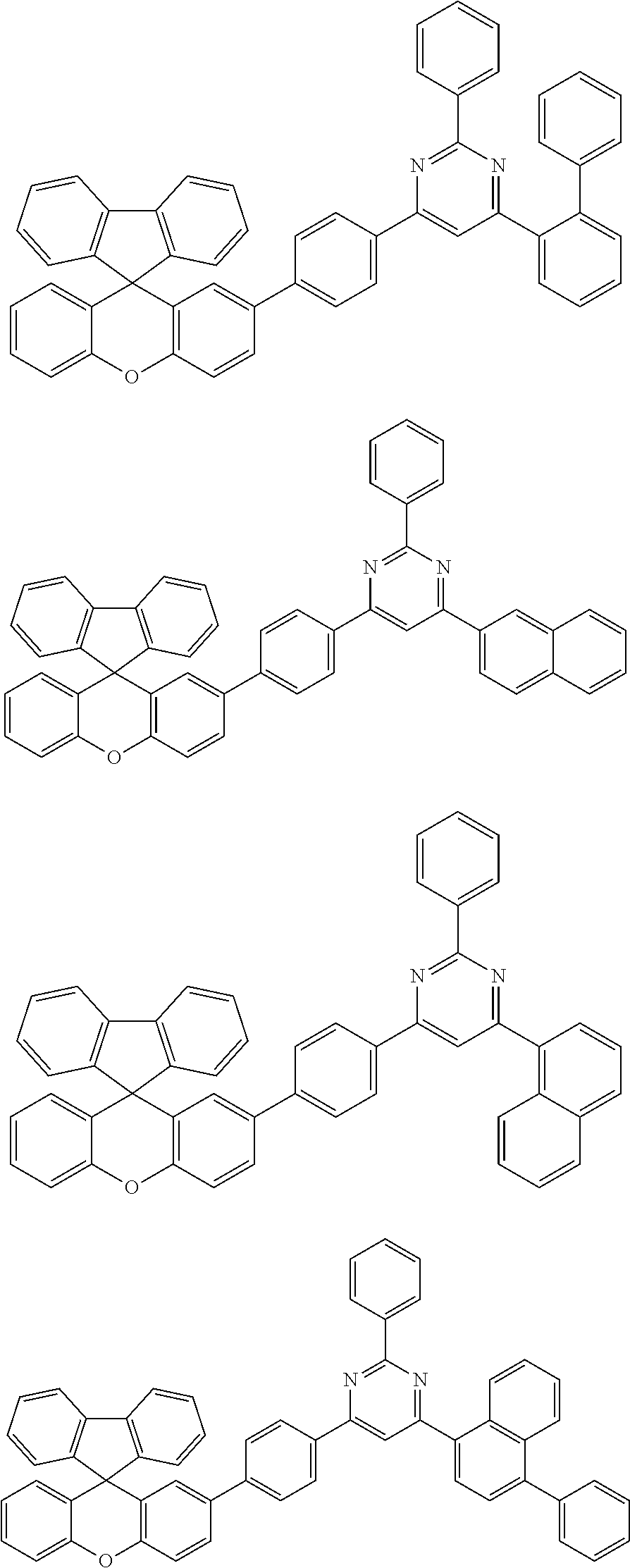


H E −H H>0.2 eV, Equation 1:
−0.3 eV<L E −L H<0.3 eV, Equation 2:
T E −T H>0.5 eV, Equation 3:
Applications Claiming Priority (3)
| Application Number | Priority Date | Filing Date | Title |
|---|---|---|---|
| KR1020170083566A KR102138410B1 (en) | 2017-06-30 | 2017-06-30 | Organic light emitting device |
| KR10-2017-0083566 | 2017-06-30 | ||
| PCT/KR2018/007423 WO2019004787A1 (en) | 2017-06-30 | 2018-06-29 | Organic light emitting element |
Publications (2)
| Publication Number | Publication Date |
|---|---|
| US20200035930A1 US20200035930A1 (en) | 2020-01-30 |
| US11462695B2 true US11462695B2 (en) | 2022-10-04 |
Family
ID=64741765
Family Applications (1)
| Application Number | Title | Priority Date | Filing Date |
|---|---|---|---|
| US16/495,087 Active 2039-09-04 US11462695B2 (en) | 2017-06-30 | 2018-06-29 | Organic light emitting element |
Country Status (4)
| Country | Link |
|---|---|
| US (1) | US11462695B2 (en) |
| KR (1) | KR102138410B1 (en) |
| CN (1) | CN110462862B (en) |
| WO (1) | WO2019004787A1 (en) |
Families Citing this family (8)
| Publication number | Priority date | Publication date | Assignee | Title |
|---|---|---|---|---|
| WO2020197170A1 (en) * | 2019-03-28 | 2020-10-01 | 주식회사 엘지화학 | Novel compound and organic light emitting device comprising the same |
| KR20200129988A (en) * | 2019-05-10 | 2020-11-18 | 주식회사 엘지화학 | Organic light emitting device |
| KR20200129994A (en) * | 2019-05-10 | 2020-11-18 | 주식회사 엘지화학 | Organic light emitting device |
| KR102444280B1 (en) * | 2019-05-10 | 2022-09-15 | 주식회사 엘지화학 | Organic light emitting device |
| KR102477844B1 (en) * | 2019-11-29 | 2022-12-15 | 주식회사 엘지화학 | Organic light emitting device |
| CN113924665B (en) * | 2019-11-29 | 2023-09-29 | 株式会社Lg化学 | organic light emitting devices |
| KR102667151B1 (en) * | 2020-08-21 | 2024-05-20 | 주식회사 엘지화학 | Organic light emitting device comprising organic compounds |
| CN116193882B (en) * | 2023-02-07 | 2026-03-10 | 京东方科技集团股份有限公司 | Light emitting device, display panel and display device |
Citations (20)
| Publication number | Priority date | Publication date | Assignee | Title |
|---|---|---|---|---|
| JP2003096072A (en) | 2001-09-26 | 2003-04-03 | Toray Ind Inc | Light-emitting element |
| US20050280008A1 (en) * | 2004-06-16 | 2005-12-22 | Eastman Kodak Company | Array of light-emitting oled microcavity pixels |
| US20110084259A1 (en) * | 2009-10-14 | 2011-04-14 | Samsung Mobile Display Co., Ltd. | Organic light-emitting diode and method of manufacturing the same |
| CN102786508A (en) | 2012-07-19 | 2012-11-21 | 南京邮电大学 | Spiro-fluorene-9,9-xanthene bipolar luminescent material, its preparation method and its application method |
| KR20150106501A (en) | 2014-03-11 | 2015-09-22 | 삼성디스플레이 주식회사 | Compound and organic light emitting device comprising same |
| US20150318501A1 (en) * | 2012-11-06 | 2015-11-05 | Basf Se | Phenoxasiline based compounds for electronic application |
| KR101593368B1 (en) | 2015-04-22 | 2016-02-11 | 주식회사 엘지화학 | Hetero-cyclic compound and organic light emitting diode comprising the same |
| US20160072077A1 (en) * | 2014-09-04 | 2016-03-10 | Samsung Display Co., Ltd. | Organic light emitting diode and organic light emitting display device including the same |
| US20160093814A1 (en) * | 2014-09-26 | 2016-03-31 | Samsung Electronics Co., Ltd. | Organometallic compound and organic light-emitting device including the same |
| US20160118599A1 (en) | 2014-10-22 | 2016-04-28 | Samsung Display Co., Ltd. | Compound and organic light-emitting device including the same |
| KR20160079514A (en) | 2014-12-26 | 2016-07-06 | (주)피엔에이치테크 | An electroluminescent compound and an electroluminescent device comprising the same |
| CN106083825A (en) | 2016-06-07 | 2016-11-09 | 石家庄诚志永华显示材料有限公司 | Pyrazines derivatives and the application in organic electroluminescence device thereof |
| KR20170067644A (en) | 2015-12-08 | 2017-06-16 | 주식회사 엘지화학 | Heterocyclic compound and organic light emitting device comprising the same |
| US20200058874A1 (en) * | 2018-08-17 | 2020-02-20 | Lg Display Co., Ltd. | Organic electroluminescence device |
| US20210217967A1 (en) * | 2018-07-25 | 2021-07-15 | Lg Chem, Ltd. | Organic light emitting device |
| US11094889B2 (en) * | 2016-02-23 | 2021-08-17 | Lg Chem, Ltd. | Heterocyclic compound and organic light emitting element comprising same |
| US20210280792A1 (en) * | 2018-12-28 | 2021-09-09 | Lg Display Co., Ltd. | Organic light emitting diode and organic light emitting device having thereof |
| US20210296589A1 (en) * | 2018-12-28 | 2021-09-23 | Lg Display Co., Ltd. | Organic light emitting diode and organic light emitting device including the same |
| US11152576B2 (en) * | 2017-05-29 | 2021-10-19 | Lg Chem, Ltd. | Organic light emitting device |
| US20210408386A1 (en) * | 2018-12-28 | 2021-12-30 | Lg Display Co., Ltd. | Organic light emitting diode and organic light emitting device including the same |
Family Cites Families (2)
| Publication number | Priority date | Publication date | Assignee | Title |
|---|---|---|---|---|
| KR100430549B1 (en) | 1999-01-27 | 2004-05-10 | 주식회사 엘지화학 | New organomattalic complex molecule for the fabrication of organic light emitting diodes |
| JP6306033B2 (en) * | 2012-11-12 | 2018-04-04 | メルク パテント ゲーエムベーハー | Materials for electronic devices |
-
2017
- 2017-06-30 KR KR1020170083566A patent/KR102138410B1/en active Active
-
2018
- 2018-06-29 US US16/495,087 patent/US11462695B2/en active Active
- 2018-06-29 CN CN201880020908.5A patent/CN110462862B/en active Active
- 2018-06-29 WO PCT/KR2018/007423 patent/WO2019004787A1/en not_active Ceased
Patent Citations (23)
| Publication number | Priority date | Publication date | Assignee | Title |
|---|---|---|---|---|
| JP2003096072A (en) | 2001-09-26 | 2003-04-03 | Toray Ind Inc | Light-emitting element |
| US20050280008A1 (en) * | 2004-06-16 | 2005-12-22 | Eastman Kodak Company | Array of light-emitting oled microcavity pixels |
| US20110084259A1 (en) * | 2009-10-14 | 2011-04-14 | Samsung Mobile Display Co., Ltd. | Organic light-emitting diode and method of manufacturing the same |
| CN102786508A (en) | 2012-07-19 | 2012-11-21 | 南京邮电大学 | Spiro-fluorene-9,9-xanthene bipolar luminescent material, its preparation method and its application method |
| US20150318501A1 (en) * | 2012-11-06 | 2015-11-05 | Basf Se | Phenoxasiline based compounds for electronic application |
| KR20150106501A (en) | 2014-03-11 | 2015-09-22 | 삼성디스플레이 주식회사 | Compound and organic light emitting device comprising same |
| US20160072077A1 (en) * | 2014-09-04 | 2016-03-10 | Samsung Display Co., Ltd. | Organic light emitting diode and organic light emitting display device including the same |
| US20160093814A1 (en) * | 2014-09-26 | 2016-03-31 | Samsung Electronics Co., Ltd. | Organometallic compound and organic light-emitting device including the same |
| KR20160047670A (en) | 2014-10-22 | 2016-05-03 | 삼성디스플레이 주식회사 | Compound and organic light emitting device comprising same |
| US20160118599A1 (en) | 2014-10-22 | 2016-04-28 | Samsung Display Co., Ltd. | Compound and organic light-emitting device including the same |
| US9722187B2 (en) * | 2014-10-22 | 2017-08-01 | Samsung Display Co., Ltd. | Compound and organic light-emitting device including the same |
| KR20160079514A (en) | 2014-12-26 | 2016-07-06 | (주)피엔에이치테크 | An electroluminescent compound and an electroluminescent device comprising the same |
| KR101593368B1 (en) | 2015-04-22 | 2016-02-11 | 주식회사 엘지화학 | Hetero-cyclic compound and organic light emitting diode comprising the same |
| US20180287069A1 (en) | 2015-12-08 | 2018-10-04 | Lg Chem, Ltd. | Heterocyclic compound and organic light emitting element comprising same |
| KR20170067644A (en) | 2015-12-08 | 2017-06-16 | 주식회사 엘지화학 | Heterocyclic compound and organic light emitting device comprising the same |
| US11094889B2 (en) * | 2016-02-23 | 2021-08-17 | Lg Chem, Ltd. | Heterocyclic compound and organic light emitting element comprising same |
| CN106083825A (en) | 2016-06-07 | 2016-11-09 | 石家庄诚志永华显示材料有限公司 | Pyrazines derivatives and the application in organic electroluminescence device thereof |
| US11152576B2 (en) * | 2017-05-29 | 2021-10-19 | Lg Chem, Ltd. | Organic light emitting device |
| US20210217967A1 (en) * | 2018-07-25 | 2021-07-15 | Lg Chem, Ltd. | Organic light emitting device |
| US20200058874A1 (en) * | 2018-08-17 | 2020-02-20 | Lg Display Co., Ltd. | Organic electroluminescence device |
| US20210280792A1 (en) * | 2018-12-28 | 2021-09-09 | Lg Display Co., Ltd. | Organic light emitting diode and organic light emitting device having thereof |
| US20210296589A1 (en) * | 2018-12-28 | 2021-09-23 | Lg Display Co., Ltd. | Organic light emitting diode and organic light emitting device including the same |
| US20210408386A1 (en) * | 2018-12-28 | 2021-12-30 | Lg Display Co., Ltd. | Organic light emitting diode and organic light emitting device including the same |
Non-Patent Citations (3)
| Title |
|---|
| CAS reg. No. 1026768-26-2, Jun. 9, 2008. (Year: 2008). * |
| CAS reg. No. 2106881-00-7, Aug. 2, 2017. (Year: 2017). * |
| International Search Report for PCT/KR2018/007423, dated Sep. 21, 2018. (Year: 2018). * |
Also Published As
| Publication number | Publication date |
|---|---|
| CN110462862A (en) | 2019-11-15 |
| WO2019004787A1 (en) | 2019-01-03 |
| KR20190003086A (en) | 2019-01-09 |
| CN110462862B (en) | 2023-02-07 |
| KR102138410B1 (en) | 2020-07-27 |
| US20200035930A1 (en) | 2020-01-30 |
Similar Documents
| Publication | Publication Date | Title |
|---|---|---|
| US11849636B2 (en) | Heterocyclic compound and organic light emitting element comprising same | |
| US11152576B2 (en) | Organic light emitting device | |
| US12239016B2 (en) | Organic light emitting element | |
| US11718606B2 (en) | Polycyclic compound and organic light emitting element comprising same | |
| US11462695B2 (en) | Organic light emitting element | |
| US10957857B2 (en) | Multicyclic compound and organic light emitting device including the same | |
| US10230056B2 (en) | Heterocyclic compound and organic light emitting element comprising same | |
| US11427572B2 (en) | Heterocyclic compound and organic light emitting element including same | |
| US20190148650A1 (en) | Organic Light Emitting Device | |
| US20210305516A1 (en) | Organic light-emitting device | |
| US11367836B2 (en) | Heterocyclic compound and organic light emitting element including same | |
| US11450819B2 (en) | Heterocyclic compound and organic light-emitting element including same | |
| US11569453B2 (en) | Polycyclic compound and organic light emitting element comprising same | |
| US10431748B2 (en) | Cyclic compound and organic light-emitting element comprising same | |
| KR102064645B1 (en) | Organic light emitting device | |
| KR102064646B1 (en) | Organic light emitting device | |
| US11653564B2 (en) | Compound and organic light-emitting device comprising same | |
| US9972785B2 (en) | Spiro-type compound and organic light emitting element comprising same | |
| US11563184B2 (en) | Heterocyclic compound and organic light emitting element containing same | |
| US9960357B2 (en) | Spiro-type compound and organic light emitting element comprising same |
Legal Events
| Date | Code | Title | Description |
|---|---|---|---|
| AS | Assignment |
Owner name: LG CHEM, LTD., KOREA, REPUBLIC OF Free format text: ASSIGNMENT OF ASSIGNORS INTEREST;ASSIGNORS:HEO, DONG UK;LEE, DONG HOON;HUH, JUNGHO;AND OTHERS;REEL/FRAME:050408/0110 Effective date: 20180430 |
|
| FEPP | Fee payment procedure |
Free format text: ENTITY STATUS SET TO UNDISCOUNTED (ORIGINAL EVENT CODE: BIG.); ENTITY STATUS OF PATENT OWNER: LARGE ENTITY |
|
| STPP | Information on status: patent application and granting procedure in general |
Free format text: NON FINAL ACTION MAILED |
|
| STPP | Information on status: patent application and granting procedure in general |
Free format text: RESPONSE TO NON-FINAL OFFICE ACTION ENTERED AND FORWARDED TO EXAMINER |
|
| STPP | Information on status: patent application and granting procedure in general |
Free format text: NON FINAL ACTION MAILED |
|
| STPP | Information on status: patent application and granting procedure in general |
Free format text: NOTICE OF ALLOWANCE MAILED -- APPLICATION RECEIVED IN OFFICE OF PUBLICATIONS |
|
| STPP | Information on status: patent application and granting procedure in general |
Free format text: PUBLICATIONS -- ISSUE FEE PAYMENT VERIFIED |
|
| STCF | Information on status: patent grant |
Free format text: PATENTED CASE |
|
| CC | Certificate of correction |