US11460377B2 - Device for microscopic sample collection - Google Patents
Device for microscopic sample collection Download PDFInfo
- Publication number
- US11460377B2 US11460377B2 US16/821,335 US202016821335A US11460377B2 US 11460377 B2 US11460377 B2 US 11460377B2 US 202016821335 A US202016821335 A US 202016821335A US 11460377 B2 US11460377 B2 US 11460377B2
- Authority
- US
- United States
- Prior art keywords
- work stand
- microscopic
- slot
- collection device
- collection
- Prior art date
- Legal status (The legal status is an assumption and is not a legal conclusion. Google has not performed a legal analysis and makes no representation as to the accuracy of the status listed.)
- Active, expires
Links
Images



Classifications
-
- G—PHYSICS
- G01—MEASURING; TESTING
- G01N—INVESTIGATING OR ANALYSING MATERIALS BY DETERMINING THEIR CHEMICAL OR PHYSICAL PROPERTIES
- G01N1/00—Sampling; Preparing specimens for investigation
- G01N1/02—Devices for withdrawing samples
-
- G—PHYSICS
- G01—MEASURING; TESTING
- G01N—INVESTIGATING OR ANALYSING MATERIALS BY DETERMINING THEIR CHEMICAL OR PHYSICAL PROPERTIES
- G01N1/00—Sampling; Preparing specimens for investigation
- G01N1/28—Preparing specimens for investigation including physical details of (bio-)chemical methods covered elsewhere, e.g. G01N33/50, C12Q
- G01N1/2813—Producing thin layers of samples on a substrate, e.g. smearing, spinning-on
-
- G—PHYSICS
- G01—MEASURING; TESTING
- G01N—INVESTIGATING OR ANALYSING MATERIALS BY DETERMINING THEIR CHEMICAL OR PHYSICAL PROPERTIES
- G01N1/00—Sampling; Preparing specimens for investigation
- G01N1/02—Devices for withdrawing samples
- G01N2001/028—Sampling from a surface, swabbing, vaporising
-
- G—PHYSICS
- G01—MEASURING; TESTING
- G01N—INVESTIGATING OR ANALYSING MATERIALS BY DETERMINING THEIR CHEMICAL OR PHYSICAL PROPERTIES
- G01N1/00—Sampling; Preparing specimens for investigation
- G01N1/28—Preparing specimens for investigation including physical details of (bio-)chemical methods covered elsewhere, e.g. G01N33/50, C12Q
- G01N1/2813—Producing thin layers of samples on a substrate, e.g. smearing, spinning-on
- G01N2001/2833—Collecting samples on a sticky, tacky, adhesive surface
Definitions
- the embodiments relate generally to microscopic sample collection devices, and more particularly to microscopic sample collection devices that use a tape-lift method.
- the surface materials vary in composition which may facilitate or inhibit microscopic sample collection. And, trace microscopic samples may be distributed unevenly across the surface plane in sub-nanogram quantities.
- the conventional tape-lift methods for collecting trace microscopic samples use water soluble tape that is wrapped around closed forceps. Once wrapped, an operator rubs the tape against a surface and collects the microscopic samples.
- using a piece of tape wrapped around forceps is inefficient. First, the tape does not come into contact evenly against the surface, and, as a result, does not efficiently collect trace amounts of microscopic samples. Second, the surface area of tape that is wrapped around forceps is small.
- swabbing technique Other conventional techniques to recover trace amounts of microscopic samples, such as swabbing technique can also be used. But when microscopic samples are collected using a swabbing technique, extra liquid is added to a target surface or to a swab. The liquid increases probability of microscopic sample contamination and dilution. Also, the swab tends to push the microscopic sample across the target surface, rather than collect the microscopic sample.
- a microscopic collection device for performing a tape-lift method that uses the least amount of tape to concentrate the most amount of trace microscopic sample.
- the microscopic collection device includes a holding element comprising a handle at one end and a collection platform connected to the holding element at another end.
- the collection platform includes a collection surface on which the microscopic sample is deposited when the device comes into contact with the target surface, and a slit. A tape is inserted through the slit and wrapped around the collection platform.
- a work stand for holding the microscopic collection device while the tape is attached to the microscopic collection device is also provided.
- the work stand includes a slit capable of holding the microscopic collection device such that the collection platform is perpendicular to the top surface of the work stand.
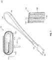
- FIG. 1 is a block diagram of a microscopic collection device, according to an embodiment.
- FIG. 2 is a block diagram of a microscopic collection device, according to an embodiment.
- FIG. 3 is a block diagram of a microscopic collection device, according to an embodiment.
- FIG. 4 is a block diagram of a microscopic collection device, according to an embodiment.
- FIG. 5 is a block diagram of a microscopic collection device, according to an embodiment.
- FIG. 6 is a block diagram of a microscopic collection device, according to an embodiment.
- FIG. 7 is a block diagram of a microscopic collection device, according to an embodiment.
- FIG. 8 is a block diagram of a microscopic collection device, according to an embodiment.
- FIG. 9 is a block diagram of a microscopic collection device, according to an embodiment.
- FIG. 10 is a block diagram of a microscopic collection device, according to an embodiment.
- FIG. 11 is a block diagram of a microscopic collection device, according to an embodiment.
- FIG. 12 is a block diagram of a work stand, according to an embodiment.
- FIG. 13 is a block diagram of a work stand, according to an embodiment.
- FIG. 14 is a block diagram of a work stand, according to an embodiment.
- microscopic sample collection devices for collecting microscopic samples from a surface of interest or a target surface.
- the microscopic collection devices described herein address a number of challenges faced by operators, including field agents and laboratory technicians, during collection of trace amounts microscopic samples deposited on a target surface.
- the microscopic collection devices utilize a tape-lift method which includes tape attached to the microscopic collection device. The tape collects the trace amount of microscopic sample when in contact with the target surface.
- microscopic collection devices described here are designed to use the least amount of tape to collect the most amount of trace microscopic sample from a target surface.
- the microscopic collection devices increase or even maximize the sample collection surface area.
- the microscopic collection devices include a flat surface area for mounting tape. The increased collection surface area results in the increased amounts of trace microscopic samples collected from the target surface.
- the microscopic collection devices also reduce the amount of tape required for sample collection and subsequent processing.
- microscopic collection devices collect a microscopic sample using a single layer of the tape.
- the single layer of tape is removed from the microscopic collection device for extraction.
- the tape is removed in a way, such that, the tape does not contain excess tape to disrupt the extraction process.
- a tape that includes a microscopic sample, such as DNA is placed in a reaction tube that includes chemicals for breaking down the cell walls and extracting the DNA from the cells. These chemicals also dissolve the tape that includes the microscopic sample.
- the dissolved tape may leave residue in the reaction tube, and the residue may inhibit the recovery of the highest yields of DNA. Because the microscopic collection devices described herein limit the excess tape, the microscopic collection devices also limit the excess residue that may interfere with DNA collection.
- the microscopic collection devices reduce opportunity for operator contamination.
- the microscopic collection devices may include a handle and a collection platform.
- the handle may be parallel to a collection platform or is at angle, such as, a 30° angle to the collection platform.
- These different embodiments allow an operator to access different types of target surfaces and also allow the operator to maintain distance from the target surfaces, and limit inadvertent interaction that may occur between the microscopic collection devices' and the target surfaces during the microscopic collection process.
- microscopic collection devices that include a handle that is parallel to a collection platform may be used to access target surfaces that are between other objects, such as, for example, shelves in a book case or floor under a couch.
- microscopic collection devices that include a handle that is at an angle to the collection platform may be used to access target surfaces that are open surfaces, such as tables, or a surfaces of objects on top of tables.
- a work stand that holds microscopic collection device(s) when an operator attaches and detaches tape from the microscopic collection device(s) further prevents inadvertent contamination.
- the work stand enables a single operator to attach and detach tape from the microscopic collection device(s), as opposed to conventional forceps that require two operators to attach and detach tape and thus increase risk of inadvertent contamination.
- microscopic collection devices collect microscopic samples.
- Microscopic samples may be deposited on a target surface, when different objects come into contact with a target surface. During contact, trace microscopic samples of one object, such as a skin cells from a hand or a finger, are transferred to the target surface.
- Example microscopic samples may include, but are not limited to, isolated cells or parts of a cell that include nucleic acids.
- nucleic acid may include deoxyribonucleic acids (“DNA”) and ribonucleic acids (“RNA”) and all combinations or sub-combination thereof that are known to a person of ordinary skill in the art.
- FIG. 1 is a block diagram of a microscopic collection device 100 , according to an embodiment.
- Microscopic collection device 100 collects microscopic samples deposited on a surface of an object, also referred to as a target surface.
- Microscopic collection device 100 includes a holding element 102 and a collection platform 104 that may be detached from holding element 102 .
- Collection platform 104 is also shown separately in FIG. 1 .
- holding element 102 also includes a support platform 106 on the first end and a handhold 108 on the second end.
- Support platform 106 may be used to attach collection platform 104 to holding element 102 .
- support platform 106 may be positioned to fit inside collection platform 104 to facilitate microscopic sample collection.
- holding element (including support platform 106 and handhold 108 ) may be 147.0 mm in length.
- handhold 108 may be 14.3 mm in width.
- support platform may be 5.0 mm in width and may fit inside collection platform 104 .
- an operator may use handhold 108 to hold and manipulate microscopic collection device 100 during microscopic sample collection.
- handhold 108 may be round, flat, shaped like a spatula, or have an ergonomic shape that facilitates operator's grip and adds balance to microscopic collection device 100 .
- collection platform 104 may be a rectangular shaped platform, having long and short sides, and having a hollow center 110 .
- hollow center 110 of collection platform 104 may be suitable to include support platform 106 that may be positioned inside collection platform 104 .
- Hollow center 110 may also be of a rectangular shape, such that the flat side of support platform 106 may be inserted into hollow center 110 .
- collection platform 104 may have length ⁇ width ⁇ height dimensions of 19 mm ⁇ 10.5 mm ⁇ 1.5 mm.
- the microscopic collection surface area of collection platform 104 that is used to collect microscopic samples from the target surface may be approximately 200 mm 2 .
- collection platform 104 may also have rounded sides.
- collection platform 104 may also include multiple slits 112 A-C.
- Slits 112 A-C may run along the length of collection platform 104 and may be positioned around the outside surface of collection platform 104 at predefined intervals.
- slit 112 A may be positioned along the long and flat side of collection platform 104 that is parallel to and faces to and/or away from the target surface.
- slits 112 B and 112 C may be positioned along the surface of collection platform 104 that is perpendicular to the target surface.
- slits 112 A-C hold tape 114 that is wrapped around collection platform 104 .
- Tape 114 may be a microscopic collection tape, such as tape known to a person of ordinary skill in the art. Tape 114 may also be water soluble tape.
- An operator may insert one edge of tape 114 into slit 112 B, such that one edge of tape 114 is inside hollow center 110 . The operator may then wrap tape 114 around collection platform 104 , as shown in a cross-section view 116 .
- Tape 114 may have an adhesive side 114 A, shown by a dashed line in FIG. 1 , and a non-adhesive side 114 B, shown by a solid line in FIG. 1 .
- tape 114 may be wrapped around collection platform 104 such that the non-adhesive side 114 B faces collection platform 104 and adhesive side 114 A faces away from collection platform 104 and faces the target surface.
- arrows 118 show a microscopic sample collection side of collection platform 114 with tape 114 wrapped around collection platform 104 .
- FIG. 2 is a block diagram of a microscopic collection device 200 , according to an embodiment.
- Microscopic collection device 200 collects microscopic samples deposited on a target surface.
- Microscopic collection device 200 includes a holding element 202 and a collection platform 204 .
- Holding element 202 and collection platform 204 may be fused together.
- microscopic collection device 200 may be 147 mm in length.
- the holding element may include a handhold 206 that facilitates an operator to hold and manipulate microscopic collection device 200 during microscopic collection.
- handhold 206 may be round, flat, shaped like a spatula, or have an ergonomic shape that facilitates operator's grip.
- the center of gravity of microscopic collection tool 200 may be located in handhold 206 .
- handhold 206 may be wide and substantial in weight, while collection platform 204 may be sleek and slender, as shown in FIG. 2 .
- Microscopic collection tool 200 having center of gravity located in handhold 206 allows collection platform 204 to rest on the target surface as the operator balances handhold 206 and operates microscopic collection tool 200 , which further reduces a chance of incidental contamination.
- collection platform 204 may be of a rectangular shape and have length ⁇ width ⁇ height dimensions of 10 mm ⁇ 19.5 mm ⁇ 0.866 mm. Collection platform 204 is also shown separately in FIG. 2 .
- collection platform 204 may include a slit 208 along the length and down the center of collection platform 204 , such that collection platform 204 is divided into a first leg 210 A and a second leg 210 B. In an embodiment, first leg 210 A and second leg 210 B are approximately the same width.
- the length of slit 208 may be less than the length of collection platform 204 , such that collection platform 204 is U shaped and comes together at the end connected to holding element 202 . In an embodiment, the length of slit 208 may vary for different microscopic collection devices 200 such that tapes of different width may be inserted into collection platform 204 .
- slit 208 holds tape 212 that is wrapped around collection platform 204 , as shown in cross section view 214 .
- an operator may insert one edge of tape 212 into slit 208 beginning at the side of collection platform 204 that faces the target surface and wrap tape 212 around both leg 210 A and leg 210 B, such that tape 212 ends on the surface of collection platform 204 that faces away from the target surface.
- tape 212 may be a microscopic collection tape such as that known to a person of ordinary skill in the art. Tape 212 may have an adhesive side 212 A and a non-adhesive side 212 B. In an embodiment, tape 212 may be wrapped around collection platform 204 such that the non-adhesive side 212 B faces collection platform 204 and adhesive side 212 A faces the target surface. In a further embodiment, arrows 216 show a microscopic sample collection side of collection platform 204 with tape 212 wrapped around collection platform 204 .
- FIG. 3 is a block diagram of a microscopic collection device 300 , according to an embodiment.
- Microscopic collection device 300 is similar to microscopic collection device 200 , and has a holding element 302 and a collection platform 304 .
- microscopic collection device 300 may be longer.
- microscopic collection device 300 may have a longer holding element 302 , such that microscopic collection device 300 has a length of 197.3 mm.
- the additional length of holding element 302 gives an operator of microscopic collection device 300 a more balanced feel.
- the longer length separates the operator from the target surface and provides further safeguards against inadvertent sample contamination.
- collection platform 304 may be a rectangular shaped platform and have length ⁇ width ⁇ height dimensions of 10 mm ⁇ 19.5 mm ⁇ 0.866 mm. In a further embodiment, the surface area of collection platform 304 that comes into contact with the target surface is approximately 20.00 mm 2 .
- FIG. 4 is a block diagram of a microscopic collection device 400 , according to an embodiment.
- Microscopic collection device 400 is similar to microscopic collection device 300 , but has a different embodiment of a collection platform 404 .
- Collection platform 404 is also shown separately in FIG. 4 .
- Collection platform 404 reduces the amount of tape that is analyzed once an operator collects a microscopic sample.
- collection platform 404 may be a rectangular shaped platform and have length ⁇ width ⁇ height dimensions of 10 mm ⁇ 19.5 mm ⁇ 1.3 mm. In a further embodiment, the surface area of collection platform 404 that comes into contact with the target surface is approximately 20.00 mm 2 .
- collection platform 404 may be divided into two legs, 406 A and 406 B by a slit 408 , such that collection platform 404 is U shaped.
- Each of legs 406 A-B also have groves 410 formed along the outside side of each leg 406 A and 406 B.
- Groves 410 are parallel to slit 408 .
- groves 410 may run along the entire length or a portion of the length of leg 406 A and 406 B.
- tape 412 may be wrapped around collection platform 404 in the same way as in microscopic collection devices 200 and 300 , as shown in cross section view 414 .
- an operator may insert one edge of tape 412 into slit 408 beginning at the microscopic sample collection side of collection platform 404 and wrap tape 412 around legs 406 A and 406 B, such that tape 412 ends on the surface of collection platform 404 that faces away from the target surface.
- each grove 410 facilitates removal of tape 412 from collection platform 404 .
- grove 410 limits tape 412 that is collected and analyzed to a section of tape 412 that came into contact with the target surface. For example, once an operator collects a microscopic sample from the target surface, the operator guides a scalpel along the formed insides of groves 410 and cuts tape 412 . The scalpel cuts a portion of tape 412 that comes into contact with the target surface from the rest of tape 412 . For example, the operator cuts away a portion of tape that faces arrows 416 . An operator than analyses portion of tape 412 that came into contact with the target surface in the reaction tube and discards the rest of tape 412 .
- FIG. 5 is a block diagram of a microscopic collection device 500 , according to an embodiment.
- Microscopic collection device 500 collects microscopic samples deposited on a target surface.
- Microscopic collection device 500 includes a holding element 502 on one side and a collection platform 504 on the other side that may be fused together. Collection platform 504 is also shown separately in FIG. 5 .
- microscopic collection device 500 may be 197.3 mm in length.
- holding element 502 may include a handhold 506 .
- Handhold 506 facilitates an operator to hold and manipulate microscopic collection device 500 during microscopic sample collection.
- handhold 506 may be round, flat, shaped like a spatula, or have an ergonomic shape that facilitates operator's grip and balances microscopic collection device 500 .
- handhold 506 may include a grove 508 .
- the grove 508 may be located on either side or both sides (not shown) of handhold 506 and, in combination with a work stand described below, allows the operator to attach and detach tape to/from collection platform 504 .
- collection platform 504 is a rectangular collection platform that includes at least two rectangular platforms.
- collection platform 504 may be divided into platforms 510 A and 510 B.
- Platform 510 A is rectangular shaped and is used to collect a microscopic sample from the target surface.
- Platform 510 B is parallel and is positioned on top of platform 510 A with a horizontal slit dividing platforms 510 A and 510 B.
- platform 510 B is also a rectangular platform.
- the length of platforms 510 A and 510 B is the same or approximately the same, while the width of platform 510 B is smaller than the width of platform 510 A.
- platforms 510 A and 510 B are fused to holding element 502 .
- collection platform 504 may have length ⁇ width ⁇ height dimensions of 10 mm ⁇ 19.5 mm ⁇ 3.9 mm. Additionally, in an embodiment, the surface area of platform 510 A that comes into contact with the target surface is approximately 20.00 mm 2 . In a further embodiment, height of 3.9 mm includes the height of platforms 510 A and 510 B and the slit that divides platforms 510 A and 510 B. For example, the height of platform 510 A and 510 B may each be 1.3 mm and the height of the horizontal gap between platform 510 A and platform 510 B may also be 1.3 mm.
- platform 510 A includes groves 512 .
- Groves 512 are positioned along the length of platform 510 and are similar to groves 410 described above. Groves 512 are used to cut away a portion of tape 516 used for microscopic sample collection, and as a result minimize excess tape 516 during the microscopic sample analysis.
- tape 516 is wrapped around collection platform 504 as shown in cross section area 514 .
- an operator may insert one edge of tape 516 between platforms 510 A and 510 B, and then continue to wrap tape 516 around the top of platform 510 B and then around the bottom of platform 510 A, and finish on top of platform 510 B.
- tape 516 includes an adhesive side 516 A and a non-adhesive side 516 B, and is wrapped around collection platform 504 , such that adhesive side 516 A faces the target surface.
- arrows 518 show a microscopic sample collection side of collection platform 504 with tape 516 wrapped around collection platform 504 .
- FIG. 6 is a block diagram of a microscopic collection device 600 , according to an embodiment.
- Microscopic collection device 600 collects microscopic samples deposited on a target surface.
- Microscopic collection device 600 includes a holding element 602 that is similar to holding element 502 .
- Microscopic collection device 600 also includes a collection platform 604 , shown separately in FIG. 6 .
- Collection platform 604 includes two platforms 606 A and 606 B.
- Platform 606 A is similar to platform 510 A described above, and is used to collect a microscopic sample from the target surface.
- Platform 606 B is parallel and is positioned on top of platform 606 A with a horizontal slit dividing platforms 606 A and 606 B.
- platforms 606 A and 606 B may be fused together and may also be fused to holding element 602 .
- platform 606 B also has a vertical slit that divides platform 606 B into two legs 608 A and 608 B, such that platform 606 B is U shaped and such that legs 608 A and 608 B come together towards the end of platform 606 B that is fused to holding element 602 .
- the length of platforms 606 A and each of legs 608 A-B is the same or approximately the same.
- the vertical slit between legs 608 A-B may be approximately 2.00 mm in one embodiment, but may also vary according to different implementations of microscopic collection device 600 .
- the vertical slit between legs 608 A and 608 B may be wide enough for microscopic tape to pass between legs 608 A and 608 B, and facilitates the operator in attaching the tape to collection platform 604 .
- collection platform 604 may have length ⁇ width ⁇ height dimensions of 10 mm ⁇ 19.5 mm ⁇ 3.9 mm, such that the surface area of platform 606 A that comes into contact with the target surface is approximately 20.00 mm 2 .
- height of 3.9 mm includes the height of platforms 606 A and 606 B and the slit that divides platforms 606 A-B.
- the height of platform 606 A and 606 B may each be 1.3 mm and the height of the horizontal slit between platform 606 A and platform 606 B may also be 1.3 mm.
- platform 606 A includes groves 612 .
- Groves 612 are positioned along the length of platform 606 A and are similar to groves 410 described above. Groves 612 are used to cut away a portion of tape 612 that was used for microscopic sample collection, and as a result minimize the excess tape 612 used during the microscopic sample analysis.
- tape 616 is wrapped around collection platform 604 as shown in cross section area 614 .
- an operator may begin with the first edge of tape 616 being on the outside of leg 608 B and then sliding tape 616 under and along the bottom surface of leg 608 B. Then the operator may slide tape 616 through the vertical slit between legs 608 A and 608 B and continue over the top of leg 608 A. Then the operator may continue along the outside edge of leg 608 A and around the bottom surface of platform 606 A, finishing at the top of leg 608 B or the top of leg 608 A.
- tape 616 includes an adhesive side 616 A and a non-adhesive side 616 B, and is wrapped around collection platform 604 , such that adhesive side 616 A faces the target surface.
- arrows 618 point to the microscopic sample collection side of collection platform 604 with tape 616 wrapped around collection platform 604 .
- FIGS. 7-11 are block diagrams of microscopic collection devices 700 - 1100 that are similar to the microscopic collection devices 200 - 600 , according to an embodiment.
- the angle may be a 45° or a 60° angle, or another angle suitable for microscopic sample collection.
- microscopic collection device 700 includes a holding element 702 and a collection platform 704 that are similar to holding element 202 and a collection platform 204 .
- holding element 702 and collection platform 704 are fused together.
- holding element 702 and collection platform 704 are fused at an approximately 30° angle at location 706 as shown in FIG. 7 . That is, when collection platform 704 faces the target surface, there is an approximately 30° angle between holding element 702 and the target surface.
- the 30° angle (or potentially another angle) between holding element 702 and collection platform 704 allows an operator to comfortably position microscopic collection device 700 against the target surface, when the target surface is a flat, open, surface, such as a floor or a table top. In an embodiment, the angle prevents holding element 702 from touching the target surface containing the microscopic sample and reduces inadvertent contamination.
- microscopic collection devices 800 - 1100 which are similar to the respective microscopic collection devices 300 - 600 , also include an angle between the respective holding elements 802 - 1102 and collection platforms 804 - 1104 at locations 806 - 1106 .
- FIG. 12 is a block diagram of a work stand 1200 , according to an embodiment.
- Work stand 1200 is operable to hold microscopic collection devices 100 - 1100 while tape is loaded onto microscopic collection devices 100 - 1100 in preparation for microscopic sample collection.
- work stand 1200 may be shaped like a rectangular prism and is placed on a flat surface, such as a table.
- the length ⁇ width ⁇ height dimensions of work stand 1200 may be 100 mm ⁇ 50 mm ⁇ 25 mm, such that the dimensions of the top and bottom surfaces of work stand 1200 are 100 mm ⁇ 50 mm, and dimensions of each of the two parallel sides of work stand 1200 are 50 mm ⁇ 20 mm and 100 mm ⁇ 20 mm.
- work stand 1200 includes two slots on the top surface, slot 1202 and slot 1204 .
- Slots 1202 and 1204 are positioned next to each other and parallel to the long side of work stand 1200 , in one embodiment.
- Slots 1202 and 1204 are capable of holding the holding elements of microscopic collection devices 100 - 1100 .
- slot 1202 is capable of holding the end of holding elements 102 - 602 , such that collection platforms 104 - 604 are perpendicular to work stand 1200 .
- slot 1202 is formed downward and toward the center of work stand 1200 .
- slot 1204 is capable of holding elements 702 - 1102 , such that collection platforms 704 - 1104 are perpendicular to the top surface of work stand 1200 .
- slot 1204 is slanted downward at a 30° angle, or another angle.
- the angle of slot 1204 is the same or about the same as the angle between a collection platform and a holding element of microscopic collection devices 700 - 1100 .
- FIG. 13 is a block diagram of a work stand 1300 , according to an embodiment.
- Work stand 1300 is capable of holding microscopic collection devices 100 - 1100 while tape is loaded onto microscopic collection devices 100 - 1100 in preparation for microscopic sample collection.
- work stand 1300 may be shaped like a rectangular prism and is placed on a flat surface, such as a table.
- the length ⁇ width ⁇ height coordinates of work stand 1300 may be 100 mm ⁇ 50 mm ⁇ 50 mm, such that the dimensions of the top and bottom surfaces of work stand 1200 are 100 mm ⁇ 50 mm, and dimensions of each of the two parallel sides of work stand 1300 are 50 mm ⁇ 50 mm and 10 mm ⁇ 50 mm.
- work stand 1300 includes three slots on the top surface, slot 1302 , slot 1304 , and slot 1306 .
- Slots 1302 and 1304 are similar to slots 1202 and 1204 that are included in work stand 1200 .
- slot 1306 also holds microscopic collection devices 100 - 1100 .
- Slot 1306 is formed on the top surface and is parallel to slots 1302 and 1304 and parallel to the length of the top surface.
- slot 1306 is capable of holding a microscopic collection device on its side, such that the side of a holding element is inserted into slot 1306 and the microscopic collection device is positioned parallel to the top surface of work stand 1302 .
- a microscopic collection device may be placed into slot 1306 for tape loading.
- work stand 1300 also includes slots 1308 .
- Slots 1308 are formed into the sides of work stand 1300 , such that slots 1308 are perpendicular to slot 1306 and parallel to the surface onto which an operator places work stand 1300 .
- slots 1308 are formed toward the bottom of the sides of work stand 1300 that are 50 mm ⁇ 50 mm.
- slots 1308 provide additional support for immobilizing the microscopic collection device when the microscopic collection device is inserted into slot 1306 .
- rubber bands or another type of bands may be inserted into one or both slots 1308 and wrapped around the microscopic collection device that is inserted into slot 1306 .
- a microscopic collection device such as microscopic collection device 500 , includes grove 508 .
- a rubber band may be inserted into slot 1306 and also into the grove, such as grove 508 to further immobilize a microscopic collection device when the tape is attached to the collection platform.
- FIG. 14 is a block diagram of a work stand 1400 , according to an embodiment.
- Work stand 1400 includes the features of work stand 1300 , such as slots 1402 , 1404 , 1406 and 1408 . Additionally, work stand 1400 is shaped as a cube, having exemplary length ⁇ width ⁇ height dimensions of 100 mm ⁇ 100 mm ⁇ 100 mm. In a non-limiting embodiment, slits 1408 may be half way down the sides of work stand 1400 .
- Work stand 1400 also has one or more slits 1410 .
- Slits 1410 are vertical slits that begin at the base of work stand 1400 and run vertically along the parallel sides of work stand 1400 (that do not include slots 1408 ) to the top surface of work stand 1400 .
- slits 1410 allow rapid heat dissipation during sterilization processes, such as sterilization by autoclaving.
- work stand 1400 may also have a hollowed base 1414 that further aids heat dissipation during the sterilization process.
- work stand 1400 may have one or more threaded holes, such as hole 1411 .
- Hole 1414 may be round and located in a corner of hollowed base 1412 of work stand 1400 , as shown in FIG. 14 . In a further embodiment, there may be a hole 1414 in each corner of the base.
- the operator may use the thread in hold 1414 to screen in a rubber foot (not shown) into each hole 1414 .
- the rubber feet stabilize work stand 1400 when an operator attaches and detaches the microscopic tape from microscopic collection devices 100 - 1100 that are inserted into slots 1402 , 1404 , and 1406 .
- the rubber feet may be removed from work stand 1400 before the sterilization process.
- microscopic collection devices 100 - 1100 and work stands 1200 - 1400 may be printed using different metals or polymers.
- microscopic collection devices 100 - 1100 and work stands 1200 - 1400 may be printed using plastic or aluminum materials.
- microscopic collection devices 100 - 1100 and work stands 1200 - 1400 may be printed using metals and/or plastics that may be sterilized, such as being flame sterilized prior to microscopic collection to impede contamination of the microscopic sample.
- references herein to “one embodiment,” “an embodiment,” “an example embodiment,” or similar phrases indicate that the embodiment described may include a particular feature, structure, or characteristic, but every embodiment may not necessarily include the particular feature, structure, or characteristic. Moreover, such phrases are not necessarily referring to the same embodiment. Further, when a particular feature, structure, or characteristic is described in connection with an embodiment, it would be within the knowledge of persons skilled in the relevant art(s) to incorporate such feature, structure, or characteristic into other embodiments whether or not explicitly mentioned or described herein.
Landscapes
- Physics & Mathematics (AREA)
- Health & Medical Sciences (AREA)
- Life Sciences & Earth Sciences (AREA)
- Chemical & Material Sciences (AREA)
- Analytical Chemistry (AREA)
- Biochemistry (AREA)
- General Health & Medical Sciences (AREA)
- General Physics & Mathematics (AREA)
- Immunology (AREA)
- Pathology (AREA)
- Sampling And Sample Adjustment (AREA)
Abstract
Description
Claims (20)
Priority Applications (1)
| Application Number | Priority Date | Filing Date | Title |
|---|---|---|---|
| US16/821,335 US11460377B2 (en) | 2015-12-17 | 2020-03-17 | Device for microscopic sample collection |
Applications Claiming Priority (2)
| Application Number | Priority Date | Filing Date | Title |
|---|---|---|---|
| US14/973,083 US10634584B2 (en) | 2015-12-17 | 2015-12-17 | Device for microscopic sample collection |
| US16/821,335 US11460377B2 (en) | 2015-12-17 | 2020-03-17 | Device for microscopic sample collection |
Related Parent Applications (1)
| Application Number | Title | Priority Date | Filing Date |
|---|---|---|---|
| US14/973,083 Continuation US10634584B2 (en) | 2015-12-17 | 2015-12-17 | Device for microscopic sample collection |
Publications (2)
| Publication Number | Publication Date |
|---|---|
| US20200217757A1 US20200217757A1 (en) | 2020-07-09 |
| US11460377B2 true US11460377B2 (en) | 2022-10-04 |
Family
ID=59067004
Family Applications (2)
| Application Number | Title | Priority Date | Filing Date |
|---|---|---|---|
| US14/973,083 Active 2038-01-02 US10634584B2 (en) | 2015-12-17 | 2015-12-17 | Device for microscopic sample collection |
| US16/821,335 Active 2036-06-10 US11460377B2 (en) | 2015-12-17 | 2020-03-17 | Device for microscopic sample collection |
Family Applications Before (1)
| Application Number | Title | Priority Date | Filing Date |
|---|---|---|---|
| US14/973,083 Active 2038-01-02 US10634584B2 (en) | 2015-12-17 | 2015-12-17 | Device for microscopic sample collection |
Country Status (1)
| Country | Link |
|---|---|
| US (2) | US10634584B2 (en) |
Families Citing this family (1)
| Publication number | Priority date | Publication date | Assignee | Title |
|---|---|---|---|---|
| US11186418B1 (en) * | 2021-05-18 | 2021-11-30 | Secure Investigation Inc. | Sexual assault evidence collection kit usable by a victim |
Citations (5)
| Publication number | Priority date | Publication date | Assignee | Title |
|---|---|---|---|---|
| US4834946A (en) * | 1987-02-05 | 1989-05-30 | Levin Andrew E | Apparatus for blot screening numerous, small volume, antibody solutions |
| US5098663A (en) * | 1988-10-24 | 1992-03-24 | Fritz Berthold | Specimen rack for specimen containers |
| AU1660697A (en) * | 1996-03-26 | 1997-10-02 | Medsearch R&D Pty.Ltd | A holder for surgical sharps in surgical dishes |
| US6451262B1 (en) * | 2000-06-19 | 2002-09-17 | Chris D. Chiodo | Dissection specimen holder |
| US20130237137A1 (en) * | 2012-03-07 | 2013-09-12 | Hantover, Inc. | Container for storing knifes, utensils, and the like having integral blade sharpener |
Family Cites Families (8)
| Publication number | Priority date | Publication date | Assignee | Title |
|---|---|---|---|---|
| US5063026A (en) * | 1990-07-11 | 1991-11-05 | Evergreen Industries, Inc. | Egg collecting apparatus |
| US5268148A (en) * | 1990-12-18 | 1993-12-07 | Saliva Diagnostic Systems, Inc. | Saliva sampling device and sample adequacy system |
| US5477863A (en) * | 1993-04-14 | 1995-12-26 | Grant; Michael A. | Collection kit with a sample collector |
| US7879293B2 (en) * | 2001-09-28 | 2011-02-01 | Orasure Technologies, Inc. | Sample collector and test device |
| US7540844B2 (en) * | 2003-08-20 | 2009-06-02 | Becton, Dickinson And Company | Cell scraper |
| US8025851B2 (en) * | 2008-04-07 | 2011-09-27 | Bamburgh Marrsh Llc | Specimen sample collection device and test system |
| CN101792105B (en) * | 2009-02-04 | 2012-09-26 | 刘伟耀 | Quantitative liquid dispenser |
| WO2014179616A1 (en) * | 2013-05-01 | 2014-11-06 | My Eco Health, Llc | Specimen observation, collection, storage and preservation device and method of use |
-
2015
- 2015-12-17 US US14/973,083 patent/US10634584B2/en active Active
-
2020
- 2020-03-17 US US16/821,335 patent/US11460377B2/en active Active
Patent Citations (5)
| Publication number | Priority date | Publication date | Assignee | Title |
|---|---|---|---|---|
| US4834946A (en) * | 1987-02-05 | 1989-05-30 | Levin Andrew E | Apparatus for blot screening numerous, small volume, antibody solutions |
| US5098663A (en) * | 1988-10-24 | 1992-03-24 | Fritz Berthold | Specimen rack for specimen containers |
| AU1660697A (en) * | 1996-03-26 | 1997-10-02 | Medsearch R&D Pty.Ltd | A holder for surgical sharps in surgical dishes |
| US6451262B1 (en) * | 2000-06-19 | 2002-09-17 | Chris D. Chiodo | Dissection specimen holder |
| US20130237137A1 (en) * | 2012-03-07 | 2013-09-12 | Hantover, Inc. | Container for storing knifes, utensils, and the like having integral blade sharpener |
Also Published As
| Publication number | Publication date |
|---|---|
| US10634584B2 (en) | 2020-04-28 |
| US20200217757A1 (en) | 2020-07-09 |
| US20170176297A1 (en) | 2017-06-22 |
Similar Documents
| Publication | Publication Date | Title |
|---|---|---|
| Ambers et al. | Direct PCR amplification of DNA from human bloodstains, saliva, and touch samples collected with microFLOQ® swabs | |
| Epp et al. | Sampling and extraction of ancient DNA from sediments | |
| Khetan et al. | Comparison of UV spectrometry and fluorometry-based methods for quantification of cell-free DNA in red cell components | |
| Marie et al. | Environmental monitoring by surface sampling for cytotoxics: a review | |
| KR200473547Y1 (en) | Reagent slot, sample tray and combination kit used in biochemical test | |
| US20190325194A1 (en) | Films for biologic analyte collection and analysis and methods of production and use thereof | |
| Karlsson et al. | Four methods of nondestructive DNA sampling from freshwater pearl mussels Margaritifera margaritifera L.(Bivalvia: Unionoida) | |
| EP2743705A3 (en) | System or method of including analytical units | |
| US11460377B2 (en) | Device for microscopic sample collection | |
| Palinauskas et al. | A new method for isolation of purified genomic DNA from haemosporidian parasites inhabiting nucleated red blood cells | |
| Costa et al. | Submicroscopic malaria parasite carriage: how reproducible are polymerase chain reaction-based methods? | |
| Delmonico et al. | Cell free DNA biology and its involvement in breast carcinogenesis | |
| Stowell et al. | Optimal DNA extractions from blood on preservation paper limits conservation genomic but not conservation genetic applications | |
| Poy et al. | Beware; gloves and equipment used during the examination of exhibits are potential vectors for transfer of DNA-containing material | |
| WO2018127887A2 (en) | Electrical cutting device | |
| US11980890B2 (en) | Device and method for tracking wells in a multi-well plate | |
| US7816142B1 (en) | Lead testing system | |
| Mármol et al. | An innovative DNA extraction method: Water versus commercial buffers | |
| Stilwell et al. | RareCyte® CTC analysis step 3: using the CytePicker® module for individual cell retrieval and subsequent whole genome amplification of circulating tumor cells for genomic analysis | |
| Sánchez-Diz et al. | Population data on 15 autosomal STRs in a sample from Colombia | |
| CN211916996U (en) | Stripping clamp | |
| Jensen et al. | DNA fingerprinting of Mycobacterium leprae strains using variable number tandem repeat (VNTR)-fragment length analysis (FLA) | |
| EP2902776A1 (en) | Storage method and storage container | |
| Gunn | Validation of the M-Vac cell collection system for forensic purposes | |
| CN107567491A (en) | For collecting the device of biomaterial from biological vestige |
Legal Events
| Date | Code | Title | Description |
|---|---|---|---|
| FEPP | Fee payment procedure |
Free format text: ENTITY STATUS SET TO UNDISCOUNTED (ORIGINAL EVENT CODE: BIG.); ENTITY STATUS OF PATENT OWNER: SMALL ENTITY |
|
| AS | Assignment |
Owner name: THE MITRE CORPORATION, VIRGINIA Free format text: ASSIGNMENT OF ASSIGNORS INTEREST;ASSIGNORS:FARRIS, MICHAEL HEATH;GEMP, KEVIN ROBERT;MASTERS, DAVID;REEL/FRAME:052164/0779 Effective date: 20151215 |
|
| FEPP | Fee payment procedure |
Free format text: ENTITY STATUS SET TO SMALL (ORIGINAL EVENT CODE: SMAL); ENTITY STATUS OF PATENT OWNER: SMALL ENTITY |
|
| STPP | Information on status: patent application and granting procedure in general |
Free format text: DOCKETED NEW CASE - READY FOR EXAMINATION |
|
| STPP | Information on status: patent application and granting procedure in general |
Free format text: NON FINAL ACTION MAILED |
|
| STPP | Information on status: patent application and granting procedure in general |
Free format text: RESPONSE TO NON-FINAL OFFICE ACTION ENTERED AND FORWARDED TO EXAMINER |
|
| STPP | Information on status: patent application and granting procedure in general |
Free format text: FINAL REJECTION MAILED |
|
| STPP | Information on status: patent application and granting procedure in general |
Free format text: DOCKETED NEW CASE - READY FOR EXAMINATION |
|
| STPP | Information on status: patent application and granting procedure in general |
Free format text: NOTICE OF ALLOWANCE MAILED -- APPLICATION RECEIVED IN OFFICE OF PUBLICATIONS |
|
| STPP | Information on status: patent application and granting procedure in general |
Free format text: PUBLICATIONS -- ISSUE FEE PAYMENT VERIFIED |
|
| STCF | Information on status: patent grant |
Free format text: PATENTED CASE |
|
| MAFP | Maintenance fee payment |
Free format text: PAYMENT OF MAINTENANCE FEE, 4TH YR, SMALL ENTITY (ORIGINAL EVENT CODE: M2551); ENTITY STATUS OF PATENT OWNER: SMALL ENTITY Year of fee payment: 4 |