US11460175B2 - Reversible mounting arm for pole-mounted light fixtures - Google Patents

Reversible mounting arm for pole-mounted light fixtures Download PDF

Info

Publication number
US11460175B2
US11460175B2 US17/144,603 US202117144603A US11460175B2 US 11460175 B2 US11460175 B2 US 11460175B2 US 202117144603 A US202117144603 A US 202117144603A US 11460175 B2 US11460175 B2 US 11460175B2
Authority
US
United States
Prior art keywords
mounting arm
mounting
curved
light fixture
sidewalls
Prior art date
Legal status (The legal status is an assumption and is not a legal conclusion. Google has not performed a legal analysis and makes no representation as to the accuracy of the status listed.)
Active
Application number
US17/144,603
Other versions
US20220221138A1 (en
Inventor
Jon Eric Gibson
Eric Chang
Current Assignee (The listed assignees may be inaccurate. Google has not performed a legal analysis and makes no representation or warranty as to the accuracy of the list.)
ABL IP Holding LLC
Original Assignee
ABL IP Holding LLC
Priority date (The priority date is an assumption and is not a legal conclusion. Google has not performed a legal analysis and makes no representation as to the accuracy of the date listed.)
Filing date
Publication date
Application filed by ABL IP Holding LLC filed Critical ABL IP Holding LLC
Priority to US17/144,603 priority Critical patent/US11460175B2/en
Assigned to ABL IP HOLDING LLC reassignment ABL IP HOLDING LLC ASSIGNMENT OF ASSIGNORS INTEREST (SEE DOCUMENT FOR DETAILS). Assignors: CHANG, ERIC, GIBSON, JON ERIC
Priority to CA3111267A priority patent/CA3111267C/en
Publication of US20220221138A1 publication Critical patent/US20220221138A1/en
Application granted granted Critical
Publication of US11460175B2 publication Critical patent/US11460175B2/en
Active legal-status Critical Current
Anticipated expiration legal-status Critical

Links

Images

Classifications

    • FMECHANICAL ENGINEERING; LIGHTING; HEATING; WEAPONS; BLASTING
    • F21LIGHTING
    • F21VFUNCTIONAL FEATURES OR DETAILS OF LIGHTING DEVICES OR SYSTEMS THEREOF; STRUCTURAL COMBINATIONS OF LIGHTING DEVICES WITH OTHER ARTICLES, NOT OTHERWISE PROVIDED FOR
    • F21V21/00Supporting, suspending, or attaching arrangements for lighting devices; Hand grips
    • F21V21/10Pendants, arms, or standards; Fixing lighting devices to pendants, arms, or standards
    • F21V21/108Arms
    • FMECHANICAL ENGINEERING; LIGHTING; HEATING; WEAPONS; BLASTING
    • F16ENGINEERING ELEMENTS AND UNITS; GENERAL MEASURES FOR PRODUCING AND MAINTAINING EFFECTIVE FUNCTIONING OF MACHINES OR INSTALLATIONS; THERMAL INSULATION IN GENERAL
    • F16MFRAMES, CASINGS OR BEDS OF ENGINES, MACHINES OR APPARATUS, NOT SPECIFIC TO ENGINES, MACHINES OR APPARATUS PROVIDED FOR ELSEWHERE; STANDS; SUPPORTS
    • F16M13/00Other supports for positioning apparatus or articles; Means for steadying hand-held apparatus or articles
    • F16M13/02Other supports for positioning apparatus or articles; Means for steadying hand-held apparatus or articles for supporting on, or attaching to, an object, e.g. tree, gate, window-frame, cycle
    • FMECHANICAL ENGINEERING; LIGHTING; HEATING; WEAPONS; BLASTING
    • F21LIGHTING
    • F21VFUNCTIONAL FEATURES OR DETAILS OF LIGHTING DEVICES OR SYSTEMS THEREOF; STRUCTURAL COMBINATIONS OF LIGHTING DEVICES WITH OTHER ARTICLES, NOT OTHERWISE PROVIDED FOR
    • F21V21/00Supporting, suspending, or attaching arrangements for lighting devices; Hand grips
    • F21V21/10Pendants, arms, or standards; Fixing lighting devices to pendants, arms, or standards
    • F21V21/116Fixing lighting devices to arms or standards
    • FMECHANICAL ENGINEERING; LIGHTING; HEATING; WEAPONS; BLASTING
    • F16ENGINEERING ELEMENTS AND UNITS; GENERAL MEASURES FOR PRODUCING AND MAINTAINING EFFECTIVE FUNCTIONING OF MACHINES OR INSTALLATIONS; THERMAL INSULATION IN GENERAL
    • F16MFRAMES, CASINGS OR BEDS OF ENGINES, MACHINES OR APPARATUS, NOT SPECIFIC TO ENGINES, MACHINES OR APPARATUS PROVIDED FOR ELSEWHERE; STANDS; SUPPORTS
    • F16M2200/00Details of stands or supports
    • F16M2200/06Arms

Definitions

  • Embodiments of the invention relate to a reversible mounting arm that can be used to mount a light fixture to a curved or flat mounting surface.
  • Many light fixtures are mounted to a pole with a mounting arm. Power comes up the pole and the wires from the light fixture extend through the mounting arm to electrically connect with power in the pole so as to power the light source(s) in the light fixture.
  • Mounting arms designed to mate with a particular pole geometry have also be provided with accessories that can be used to adapt the mounting arm for use with different pole geometries.
  • accessories add both expense to the assembly and complexity to the installation process.
  • Embodiments of the present invention provide a reversible mounting arm that is universal in that it can be used to mount a light fixture to either a flat or curved mounting surface, such as, but not limited to, a round or rectilinear-shaped pole. More specifically, one end of the mounting arm is designed for mating with a round pole having a curved sidewall (or other curved mounting surfaces) whereas the opposing end of the mounting arm is designed for mating with poles having a flat sidewall (or other flat mounting surfaces).
  • the mounting arm is integral and can come ready for use with different pole geometries without requiring any accessories.
  • FIG. 1 is a top front perspective view of an embodiment of a mounting arm and light fixture.
  • FIG. 2 is a top rear perspective view of the mounting arm and light fixture of FIG. 1 .
  • FIG. 3 is an exploded view of the mounting arm and light fixture of FIG. 1 .
  • FIG. 4 is a top left perspective view of the mounting arm of FIG. 1 in isolation.
  • FIG. 5 is a top right perspective view of the mounting arm of FIG. 1 in isolation.
  • FIG. 6 is a side elevation view of the mounting arm of FIG. 1 in isolation.
  • FIG. 7 is a top plan view of the mounting arm of FIG. 1 in isolation.
  • FIG. 8 is an end view of the mounting arm of FIG. 1 in isolation.
  • FIG. 9 is a top rear perspective view of the light fixture of FIG. 1 in isolation.
  • FIG. 10 is a rear elevation view of the light fixture of FIG. 1 in isolation.
  • FIG. 11 is a top plan view of the mounting arm and light fixture of FIG. 1 attached to a square pole.
  • FIG. 12 is a top plan view of the mounting arm and light fixture of FIG. 1 attached to a round pole.
  • FIG. 13 is a top plan view of the mounting arm and light fixture of FIG. 1 attached to a mounting plate.
  • Embodiments of the present invention provide a reversible mounting arm that is universal in that it can be used to mount a light fixture to either a flat or curved mounting surface, such as, but not limited to, a round or rectilinear-shaped pole. More specifically, one end of the mounting arm is designed for mating with a round pole having a curved sidewall (or other curved mounting surfaces) whereas the opposing end of the mounting arm is designed for mating with poles having a flat sidewall (or other flat mounting surfaces).
  • the mounting arm is integral and comes ready for use with different pole geometries without requiring any accessories.
  • FIGS. 1-3 show an embodiment of the mounting arm 10 and a light fixture 30 .
  • the mounting arm 10 has a mounting arm body 12 that extends along a longitudinal axis. Note that while the mounting arm body 12 is shown as straight and of consistent outer cross-sectional shape or profile, in other embodiments the mounting arm body 12 can be bent, curved, etc. and its outer profile can vary along its length.
  • the mounting arm body 12 can be of any shape provided there is sufficient contact points on each end for engagement with a mounting surface. While the disclosed mounting arm body 12 is shown having a square cross-sectional shape formed with four sidewalls, it other embodiments the mounting arm body 12 has different shapes formed with fewer (e.g., 1, 2, or 3) or more sidewalls.
  • the mounting arm body 12 has a generally rectilinear cross-sectional shape or profile defined by sidewalls 14 a - 14 d that terminate in end edges on opposing ends of the mounting arm.
  • the mounting arm body 12 can be generally hollow to permit wires to pass unimpeded between the pole and the light fixture.
  • At least one mounting aperture 16 is provided within the mounting arm body 12 .
  • the mounting aperture 16 has an axis that extends substantially parallel or parallel with the longitudinal axis of the mounting arm body 12 .
  • two mounting apertures 16 are formed along the inner surface of opposing sidewalls 14 a , 14 c .
  • the number, shape and/or location of the mounting apertures 16 can deviate from what is shown in the figures.
  • the mounting arm body 12 includes two ends—a straight end 18 and a curved end 20 , each of which is formed integrally in the mounting arm body 12 .
  • Each sidewall 14 a - 14 d terminates in a straight edge (edges 22 a - 22 d ) at the straight end 18 .
  • the sidewalls 14 a - 14 d at the curved end 20 terminate in opposing straight edges 24 a , 24 b and opposing curved edges 26 a , 26 b that extend between the opposing straight edges 24 a , 24 b .
  • the curved edges 26 a , 26 b curve inwardly in a direction toward the straight end 18 and are symmetrical about the longitudinal axis of the mounting arm 10 .
  • the radius of curvature of the curved edges 26 a , 26 b may be the same or different from each other. In many embodiments, the radius of curvature will be the same. In some embodiments, the radius of curvature of the curved edges 26 a , 26 b can be between 1 and 6 inches, inclusive; between 1 and 5 inches, inclusive; between 1 and 4 inches, inclusive; between 1 and 3 inches, inclusive; and between 1.5 and 3 inches, inclusive, but these ranges are not limiting.
  • a universal mounting arm 10 is provided for use with poles or surfaces with curvatures different from that of curved edges 26 a , 26 b .
  • a mounting arm 10 having curved edges 26 a , 26 b sized to fit a small pole diameter can be used on a pole with a larger diameter as there will still be two points of contacts with the pole—i.e., the opposing straight edges 24 a , 24 b on the curved end 20 of the mounting arm 10 will still contact the pole.
  • Embodiments of the mounting arm 10 disclosed herein may be mounted on poles of any size, including, but not limited to, poles having diameters of 3 to 6 inches.
  • a gasket can be, but does not have to be, interposed between the pole and mounting arm 10 to seal any gaps between the two.
  • the mounting arm 10 can be formed of any material having suitable structural integrity to support the weight of a light fixture. Suitable materials may include, but are not limited to, polymeric or metallic (e.g., steel, aluminum, etc.) materials.
  • the mounting arm 10 may be formed using various methods, including, but not limited to, molding, extruding, casting, etc. In some embodiments, the mounting arm 10 is formed from extruded aluminum. Formation via an extrusion process is a cost-effective and simple way to manufacture mounting arms of different lengths.
  • the curved edges 26 a , 26 b may be formed via machining after the mounting arm has been extruded. However, other means may be used to form the curved edges 26 a , 26 b.
  • FIGS. 9 and 10 show an embodiment of a light fixture 30 to be mounted using the mounting arm 10 .
  • the light fixture 30 includes an attachment portion 32 formed in a wall 34 of the light fixture 30 .
  • the mounting arm 10 is designed to engage the attachment portion 32 to secure the light fixture to the pole or other mounting surface.
  • the attachment portion 32 can be recessed within the light fixture wall 34 and be shaped to have the same or substantially the same shape as that of the mounting arm 10 . In this way, the mounting arm 10 can seat within the recessed attachment portion 32 , as discussed in more detail below.
  • the attachment portion 32 also includes one or more securing apertures 36 and a wire aperture 38 through which wiring from the light fixture 30 can pass out of the light fixture 30 and to the pole.
  • the internal surface of the securing apertures 36 can be, but do not have to be, threaded.
  • the mounting arm 10 is attached to the light fixture 30 .
  • Fasteners such as bolts 40 (see FIG. 3 ), are secured within the securing apertures 36 in the light fixture 30 . If the securing apertures 36 are threaded, the bolts 40 can be screwed directly into the light fixture 30 . In other embodiments, the bolts 40 can be passed through the securing apertures 36 and secured in place with nuts.
  • the mounting arm 10 can then be mated with the light fixture 30 by inserting the bolts 40 through the mounting apertures 16 in the mounting arm 10 .
  • the mounting arm 10 is oriented such that the curved end 20 of the mounting arm 10 engages the light fixture 30 .
  • the curved end 20 is received within the recessed attachment portion 32 . In this way, the curved nature of the curved end 20 is concealed and the joint between the light fixture 30 and mounting arm 10 is not exposed, which helps with water shedding and prevents ingress of undesirable elements, such a moisture and dirt, into the joint.
  • the orientation of the mounting arm 10 is reversed, with the straight end 18 positioned within the recessed attachment portion 32 .
  • the wires from the light fixture 30 are threaded through the mounting arm 10 .
  • the opposing end of the mounting arm (the end that is not mated with the light fixture 30 , which can be either the straight end 18 or curved end 20 depending on the geometry of the pole) is then attached to the pole.
  • An aperture (not shown) is provided in the sidewall of the pole.
  • the mounting arm 10 (with associated light fixture 30 ) is positioned such that the bolts 40 extend through fastener receiving apertures (not shown) in the pole.
  • a securing plate 52 and nuts/washers 54 may be used to lock the bolts 40 into the pole.
  • the straight edges 22 a - 22 d of the straight end 18 of mounting arm 10 abut the pole 50 .
  • the straight edges 24 a , 24 b of the curved end 20 of mounting arm 10 abut the pole 58 .
  • the curved edges 26 a , 26 b of the curved end 20 may or may not abut the pole 58 depending on the radius of curvature of each of the curved edges 26 a , 26 b and the pole 58 .
  • a gasket (not shown) can be, but does not have to be, used at the interface between the mounting arm 10 and the pole 50 , 58 to seal the joint.
  • the necessary electrical connections are then made within the pole between the power supply in the pole and the wires from the light fixture 30 . Installation will typically involve removal of the cap or cover at the top of the pole so as to enable access to the interior of the pole, both for mounting and electrical connection purposes.
  • the mounting arm 10 is described for use with a pole, its utility is not so limited. Rather, it can be used to secure a light fixture 30 to any mounting surface, including, but not limited to, walls, ceilings, etc.
  • the mounting arm 10 is used to secure a light fixture 30 to a wall bracket 60 that is attached to a wall (see FIG. 13 ).
  • the mounting arm 10 disclosed herein may be used with any type of light fixture 30 having shapes, sizes, light sources, etc. of any kind. Embodiments of the mounting arm 10 disclosed here are in no way intended to be limited to use with a particular light fixture.

Abstract

A reversible mounting arm that is universal in that it can be used to mount a light fixture to either a flat or curved mounting surface, such as, but not limited to, a round or rectilinear-shaped pole. More specifically, one end of the mounting arm is designed for mating with a round pole having a curved sidewall (or other curved mounting surfaces) whereas the opposing end of the mounting arm is designed for mating with poles having a flat sidewall (or other flat mounting surfaces).

Description

FIELD
Embodiments of the invention relate to a reversible mounting arm that can be used to mount a light fixture to a curved or flat mounting surface.
BACKGROUND OF THE INVENTION
Many light fixtures, particularly outdoor fixtures, are mounted to a pole with a mounting arm. Power comes up the pole and the wires from the light fixture extend through the mounting arm to electrically connect with power in the pole so as to power the light source(s) in the light fixture.
Traditionally, different mounting arms have been provided depending on the shape of the pole onto which the light fixture is to be mounted. For example, end edges of a mounting arm designed to mate with a rectilinear-shaped pole need to be straight whereas end edges of a mounting arm designed to mate with a round pole need to be curved. In this way, the end of the mounting arm joins flush with the pole to create a seal between the two to prevent ingress of water and other contaminants harmful to the wiring as well as to impart a polished appearance to the assembly.
Mounting arms designed to mate with a particular pole geometry have also be provided with accessories that can be used to adapt the mounting arm for use with different pole geometries. However, such accessories add both expense to the assembly and complexity to the installation process.
BRIEF SUMMARY
The terms “invention,” “the invention,” “this invention” and “the present invention” used in this patent are intended to refer broadly to all of the subject matter of this patent and the patent claims below. Statements containing these terms should be understood not to limit the subject matter described herein or to limit the meaning or scope of the patent claims below. Embodiments of the invention covered by this patent are defined by the claims below, not this summary. This summary is a high-level overview of various aspects of the invention and introduces some of the concepts that are further described in the Detailed Description section below. This summary is not intended to identify key or essential features of the claimed subject matter, nor is it intended to be used in isolation to determine the scope of the claimed subject matter. The subject matter should be understood by reference to appropriate portions of the entire specification of this patent, any or all drawings and each claim.
Embodiments of the present invention provide a reversible mounting arm that is universal in that it can be used to mount a light fixture to either a flat or curved mounting surface, such as, but not limited to, a round or rectilinear-shaped pole. More specifically, one end of the mounting arm is designed for mating with a round pole having a curved sidewall (or other curved mounting surfaces) whereas the opposing end of the mounting arm is designed for mating with poles having a flat sidewall (or other flat mounting surfaces). The mounting arm is integral and can come ready for use with different pole geometries without requiring any accessories.
BRIEF DESCRIPTION OF THE DRAWINGS
A further understanding of the nature and advantages of various embodiments may be realized by reference to the following figures. In the appended figures, similar components or features may have the same reference label. Further, various components of the same type may be distinguished by following the reference label by a dash and a second label that distinguishes among the similar components. If only the first reference label is used in the specification, the description is applicable to any one of the similar components having the same first reference label irrespective of the second reference label.
FIG. 1 is a top front perspective view of an embodiment of a mounting arm and light fixture.
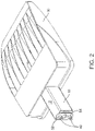
FIG. 2 is a top rear perspective view of the mounting arm and light fixture of FIG. 1.
FIG. 3 is an exploded view of the mounting arm and light fixture of FIG. 1.
FIG. 4 is a top left perspective view of the mounting arm of FIG. 1 in isolation.
FIG. 5 is a top right perspective view of the mounting arm of FIG. 1 in isolation.
FIG. 6 is a side elevation view of the mounting arm of FIG. 1 in isolation.
FIG. 7 is a top plan view of the mounting arm of FIG. 1 in isolation.
FIG. 8 is an end view of the mounting arm of FIG. 1 in isolation.
FIG. 9 is a top rear perspective view of the light fixture of FIG. 1 in isolation.
FIG. 10 is a rear elevation view of the light fixture of FIG. 1 in isolation.
FIG. 11 is a top plan view of the mounting arm and light fixture of FIG. 1 attached to a square pole.
FIG. 12 is a top plan view of the mounting arm and light fixture of FIG. 1 attached to a round pole.
FIG. 13 is a top plan view of the mounting arm and light fixture of FIG. 1 attached to a mounting plate.
DETAILED DESCRIPTION
The subject matter of embodiments of the present invention is described here with specificity to meet statutory requirements, but this description is not necessarily intended to limit the scope of the claims. The claimed subject matter may be embodied in other ways, may include different elements or steps, and may be used in conjunction with other existing or future technologies. This description should not be interpreted as implying any particular order or arrangement among or between various steps or elements except when the order of individual steps or arrangement of elements is explicitly described.
Embodiments of the present invention provide a reversible mounting arm that is universal in that it can be used to mount a light fixture to either a flat or curved mounting surface, such as, but not limited to, a round or rectilinear-shaped pole. More specifically, one end of the mounting arm is designed for mating with a round pole having a curved sidewall (or other curved mounting surfaces) whereas the opposing end of the mounting arm is designed for mating with poles having a flat sidewall (or other flat mounting surfaces). The mounting arm is integral and comes ready for use with different pole geometries without requiring any accessories.
FIGS. 1-3 show an embodiment of the mounting arm 10 and a light fixture 30. The mounting arm 10 has a mounting arm body 12 that extends along a longitudinal axis. Note that while the mounting arm body 12 is shown as straight and of consistent outer cross-sectional shape or profile, in other embodiments the mounting arm body 12 can be bent, curved, etc. and its outer profile can vary along its length. The mounting arm body 12 can be of any shape provided there is sufficient contact points on each end for engagement with a mounting surface. While the disclosed mounting arm body 12 is shown having a square cross-sectional shape formed with four sidewalls, it other embodiments the mounting arm body 12 has different shapes formed with fewer (e.g., 1, 2, or 3) or more sidewalls.
In the illustrated embodiment (see FIGS. 4-8), the mounting arm body 12 has a generally rectilinear cross-sectional shape or profile defined by sidewalls 14 a-14 d that terminate in end edges on opposing ends of the mounting arm. The mounting arm body 12 can be generally hollow to permit wires to pass unimpeded between the pole and the light fixture. At least one mounting aperture 16 is provided within the mounting arm body 12. In some embodiments, the mounting aperture 16 has an axis that extends substantially parallel or parallel with the longitudinal axis of the mounting arm body 12. In the illustrated embodiment, two mounting apertures 16 are formed along the inner surface of opposing sidewalls 14 a, 14 c. However, the number, shape and/or location of the mounting apertures 16 can deviate from what is shown in the figures.
As best seen in FIGS. 4, 5, and 7, the mounting arm body 12 includes two ends—a straight end 18 and a curved end 20, each of which is formed integrally in the mounting arm body 12. Each sidewall 14 a-14 d terminates in a straight edge (edges 22 a-22 d) at the straight end 18. In contrast, the sidewalls 14 a-14 d at the curved end 20 terminate in opposing straight edges 24 a, 24 b and opposing curved edges 26 a, 26 b that extend between the opposing straight edges 24 a, 24 b. In some embodiments, the curved edges 26 a, 26 b curve inwardly in a direction toward the straight end 18 and are symmetrical about the longitudinal axis of the mounting arm 10. The radius of curvature of the curved edges 26 a, 26 b may be the same or different from each other. In many embodiments, the radius of curvature will be the same. In some embodiments, the radius of curvature of the curved edges 26 a, 26 b can be between 1 and 6 inches, inclusive; between 1 and 5 inches, inclusive; between 1 and 4 inches, inclusive; between 1 and 3 inches, inclusive; and between 1.5 and 3 inches, inclusive, but these ranges are not limiting. While the mounting arm 10 may be manufactured so that the curved edges 26 a, 26 b precisely match the curvature of a round pole or other curved mounting surface, in some embodiments a universal mounting arm 10 is provided for use with poles or surfaces with curvatures different from that of curved edges 26 a, 26 b. For example, a mounting arm 10 having curved edges 26 a, 26 b sized to fit a small pole diameter can be used on a pole with a larger diameter as there will still be two points of contacts with the pole—i.e., the opposing straight edges 24 a, 24 b on the curved end 20 of the mounting arm 10 will still contact the pole. Embodiments of the mounting arm 10 disclosed herein may be mounted on poles of any size, including, but not limited to, poles having diameters of 3 to 6 inches. In such embodiments, a gasket can be, but does not have to be, interposed between the pole and mounting arm 10 to seal any gaps between the two.
The mounting arm 10 can be formed of any material having suitable structural integrity to support the weight of a light fixture. Suitable materials may include, but are not limited to, polymeric or metallic (e.g., steel, aluminum, etc.) materials. The mounting arm 10 may be formed using various methods, including, but not limited to, molding, extruding, casting, etc. In some embodiments, the mounting arm 10 is formed from extruded aluminum. Formation via an extrusion process is a cost-effective and simple way to manufacture mounting arms of different lengths. The curved edges 26 a, 26 b may be formed via machining after the mounting arm has been extruded. However, other means may be used to form the curved edges 26 a, 26 b.
FIGS. 9 and 10 show an embodiment of a light fixture 30 to be mounted using the mounting arm 10. The light fixture 30 includes an attachment portion 32 formed in a wall 34 of the light fixture 30. The mounting arm 10 is designed to engage the attachment portion 32 to secure the light fixture to the pole or other mounting surface. The attachment portion 32 can be recessed within the light fixture wall 34 and be shaped to have the same or substantially the same shape as that of the mounting arm 10. In this way, the mounting arm 10 can seat within the recessed attachment portion 32, as discussed in more detail below. The attachment portion 32 also includes one or more securing apertures 36 and a wire aperture 38 through which wiring from the light fixture 30 can pass out of the light fixture 30 and to the pole. The internal surface of the securing apertures 36 can be, but do not have to be, threaded.
In use, the mounting arm 10 is attached to the light fixture 30. Fasteners, such as bolts 40 (see FIG. 3), are secured within the securing apertures 36 in the light fixture 30. If the securing apertures 36 are threaded, the bolts 40 can be screwed directly into the light fixture 30. In other embodiments, the bolts 40 can be passed through the securing apertures 36 and secured in place with nuts.
The mounting arm 10 can then be mated with the light fixture 30 by inserting the bolts 40 through the mounting apertures 16 in the mounting arm 10. If the light fixture 30 is to be mounted on a flat surface (such as a sidewall of a rectilinear pole), the mounting arm 10 is oriented such that the curved end 20 of the mounting arm 10 engages the light fixture 30. For example, in the illustrated embodiment, the curved end 20 is received within the recessed attachment portion 32. In this way, the curved nature of the curved end 20 is concealed and the joint between the light fixture 30 and mounting arm 10 is not exposed, which helps with water shedding and prevents ingress of undesirable elements, such a moisture and dirt, into the joint. If the light fixture 30 is to be mounted on a curved surface (such as a round pole), the orientation of the mounting arm 10 is reversed, with the straight end 18 positioned within the recessed attachment portion 32. The wires from the light fixture 30 are threaded through the mounting arm 10.
The opposing end of the mounting arm (the end that is not mated with the light fixture 30, which can be either the straight end 18 or curved end 20 depending on the geometry of the pole) is then attached to the pole. An aperture (not shown) is provided in the sidewall of the pole. The mounting arm 10 (with associated light fixture 30) is positioned such that the bolts 40 extend through fastener receiving apertures (not shown) in the pole. A securing plate 52 and nuts/washers 54 (see FIG. 3) may be used to lock the bolts 40 into the pole.
When the mounting arm 10 is attached to a pole having a flat sidewall (such as the square pole 50 shown in FIG. 11), the straight edges 22 a-22 d of the straight end 18 of mounting arm 10 abut the pole 50. When the mounting arm 10 is attached to a pole having a curved sidewall (such as the round pole 58 shown in FIG. 12), the straight edges 24 a, 24 b of the curved end 20 of mounting arm 10 abut the pole 58. The curved edges 26 a, 26 b of the curved end 20 may or may not abut the pole 58 depending on the radius of curvature of each of the curved edges 26 a, 26 b and the pole 58. A gasket (not shown) can be, but does not have to be, used at the interface between the mounting arm 10 and the pole 50, 58 to seal the joint. The necessary electrical connections are then made within the pole between the power supply in the pole and the wires from the light fixture 30. Installation will typically involve removal of the cap or cover at the top of the pole so as to enable access to the interior of the pole, both for mounting and electrical connection purposes.
While the mounting arm 10 is described for use with a pole, its utility is not so limited. Rather, it can be used to secure a light fixture 30 to any mounting surface, including, but not limited to, walls, ceilings, etc. For example, in some embodiments the mounting arm 10 is used to secure a light fixture 30 to a wall bracket 60 that is attached to a wall (see FIG. 13). Moreover, the mounting arm 10 disclosed herein may be used with any type of light fixture 30 having shapes, sizes, light sources, etc. of any kind. Embodiments of the mounting arm 10 disclosed here are in no way intended to be limited to use with a particular light fixture.
The foregoing is provided for purposes of illustrating, explaining, and describing various embodiments. Having described these embodiments, it will be recognized by those of skill in the art that various modifications, alternative constructions, and equivalents may be used without departing from the spirit of what is disclosed. Different arrangements of the components depicted in the drawings or described above, as well as additional components and steps not shown or described, are possible. Certain features and subcombinations of features disclosed herein are useful and may be employed without reference to other features and subcombinations. Additionally, a number of well-known processes and elements have not been described in order to avoid unnecessarily obscuring the embodiments. Embodiments have been described for illustrative and not restrictive purposes, and alternative embodiments will become apparent to readers of this patent. Accordingly, embodiments are not limited to those described above or depicted in the drawings, and various modifications can be made without departing from the scope of the claims below. Embodiments covered by this patent are defined by the claims below, and not by the brief summary and the detailed description.
It should be noted that the systems and devices discussed above are intended merely to be examples. It must be stressed that various embodiments may omit, substitute, or add various procedures or components as appropriate. Also, features described with respect to certain embodiments may be combined in various other embodiments. Different aspects and elements of the embodiments may be combined in a similar manner. Also, it should be emphasized that technology evolves and, thus, many of the elements are examples and should not be interpreted to limit the scope of the invention.
Specific details are given in the description to provide a thorough understanding of the embodiments. However, it will be understood by one of ordinary skill in the art that the embodiments may be practiced without these specific details. For example, well-known structures and techniques have been shown without unnecessary detail in order to avoid obscuring the embodiments. This description provides example embodiments only, and is not intended to limit the scope, applicability, or configuration of the invention. Rather, the preceding description of the embodiments will provide those skilled in the art with an enabling description for implementing embodiments of the invention. Various changes may be made in the function and arrangement of elements without departing from the spirit and scope of the invention.
Having described several embodiments, it will be recognized by those of skill in the art that various modifications, alternative constructions, and equivalents may be used without departing from the spirit of the invention. For example, the above elements may merely be a component of a larger system, wherein other rules may take precedence over or otherwise modify the application of the invention. Also, a number of steps may be undertaken before, during, or after the above elements are considered. Accordingly, the above description should not be taken as limiting the scope of the invention.

Claims (22)

What is claimed is:
1. A mounting arm for mounting a light fixture to a mounting surface, the mounting arm comprising a plurality of sidewalls that define a substantially hollow mounting arm body extending along a mounting arm axis and having a straight end and a curved end opposite the straight end, wherein each of the plurality of sidewalls terminates at the straight end in a straight edge integral to the mounting arm body and wherein at least one of the plurality of sidewalls terminates at the curved end in a curved edge integral to the mounting arm body, wherein the curved edge curves inwardly in a direction toward the straight end of the mounting arm and is symmetrical about the mounting arm axis, and wherein at least one mounting aperture is provided within the mounting arm body.
2. The mounting arm of claim 1, wherein the plurality of sidewalls comprises at least four sidewalls and wherein the at least one of the plurality of sidewalls that terminates at the curved end in the curved edge comprises a first opposing pair of the at least four sidewalls.
3. The mounting arm of claim 2, wherein a second opposing pair of the at least four sidewalls terminates at the curved end in a straight edge integral to the mounting arm body.
4. The mounting arm of claim 3, wherein the at least four sidewalls is exactly four sidewalls.
5. The mounting arm of claim 1, wherein the curved edge comprises a radius of curvature of 1 to 3 inches, inclusive.
6. The mounting arm of claim 1, wherein the at least one mounting aperture is formed integrally with one of the plurality of sidewalls.
7. The mounting arm of claim 1, wherein the at least one mounting aperture comprises a mounting aperture axis that is substantially parallel to the mounting arm axis.
8. The mounting arm of claim 1, wherein the mounting surface comprises a flat mounting surface and wherein the straight edge of each of the plurality of sidewalls at the straight end is configured to contact the flat mounting surface when the light fixture is mounted on the flat mounting surface with the mounting arm.
9. The mounting arm of claim 1, wherein the mounting surface comprises a curved mounting surface, wherein at least one of the plurality of sidewalls terminates at the curved end in a straight edge that is integral to the mounting arm body and that is configured to contact the curved mounting surface when the light fixture is mounted on the curved mounting surface with the mounting arm.
10. The mounting arm of claim 9, wherein the curved edge at the curved end is configured to contact the curved mounting surface when the light fixture is mounted on the curved mounting surface with the mounting arm.
11. The mounting arm of claim 10, wherein the curved edge comprises a radius of curvature and wherein the curved mounting surface comprises a radius of curvature that is substantially the same as the radius of curvature of the curved edge.
12. The mounting arm of claim 1, wherein the mounting arm comprises an aluminum extrusion.
13. The mounting arm of claim 1, wherein the mounting arm body comprises a length and an outer profile that is consistent along the length of the mounting arm body.
14. A light fixture assembly comprising:
a. a light fixture comprising a housing wall and a recessed portion in the housing wall having a recess shape; and
b. a mounting arm comprising four sidewalls that define a substantially hollow mounting arm body extending along a mounting arm axis and having a mounting arm cross-sectional shape, a straight end, and a curved end opposite the straight end, wherein:
i. each of the four sidewalls at the straight end terminate in a straight edge integral to the mounting arm body;
ii. a first opposing pair of the four sidewalls terminates at the curved end in a curved edge integral to the mounting arm body and that curves inwardly in a direction toward the straight end of the mounting arm and that is symmetrical about the mounting arm axis; and
iii. a second opposing pair of the four sidewalls terminate at the curved end in a straight edge integral to the mounting arm body,
wherein the recessed portion is configured to receive the straight end when the mounting arm is in a first orientation and the curved end when the mounting arm is in a second orientation.
15. The light fixture assembly of claim 14, wherein the light fixture further comprises at least one securing aperture formed in the recessed portion and having a securing aperture axis and wherein the mounting arm further comprises at least one mounting aperture provided within the mounting arm body and having a mounting aperture axis, wherein, when the straight end or the curved end of the mounting arm is received within the recessed portion of the light fixture, the securing aperture axis and the mounting aperture axis are substantially collinear.
16. The light fixture assembly of claim 15, further comprising a fastener that extends at least partially through the at least one securing aperture and the at least one mounting aperture.
17. The light fixture of claim 16, wherein an inner surface of the at least one securing aperture is threaded and wherein an end of the fastener is threaded such that the end of the fastener is screwed directly into the at least one securing aperture.
18. The light fixture assembly of claim 14, wherein the recessed shape and the mounting arm cross-sectional shape are approximately the same.
19. A method of mounting a light fixture onto a mounting surface comprising:
a. providing a light fixture having a housing wall and a recessed portion in the housing wall having a recess shape, wherein at least one securing aperture having a securing aperture axis is formed in the recessed portion;
b. providing a mounting arm comprising four sidewalls that define a substantially hollow mounting arm body extending along a mounting arm axis and having a mounting arm cross-sectional shape, a straight end, and a curved end opposite the straight end, wherein:
i. each of the four sidewalls at the straight end terminate in a straight edge integral to the mounting arm body;
ii. a first opposing pair of the four sidewalls terminates at the curved end in a curved edge integral to the mounting arm body and that curves inwardly in a direction toward the straight end of the mounting arm and that is symmetrical about the mounting arm axis;
iii. a second opposing pair of the four sidewalls terminate at the curved end in a straight edge integral to the mounting arm body; and
iv. at least one mounting aperture having a mounting aperture axis is provided within the mounting arm body; and
c. mounting the mounting arm between the light fixture and mounting surface such that:
i. if the mounting surface is flat, the curved end of the mounting arm is positioned within the recessed portion of the housing wall and the straight end of the mounting arm is adjacent the mounting surface; and
ii. if the mounting surface is curved, the straight end of the mounting arm is positioned within the recessed portion of the housing wall and the curved end of the mounting arm is adjacent the mounting surface.
20. The method of claim 19, wherein positioning the mounting arm between the light fixture and mounting surface comprises securing a first end of a fastener to the light fixture and positioning the fastener within the at least one mounting aperture of the mounting arm.
21. The method of claim 20, wherein an internal surface of the at least one securing aperture of the light fixture is threaded, wherein the first end of the fastener is threaded, and wherein securing the first end of the fastener to the light fixture comprises screwing the first end of the fastener into the at least one securing aperture.
22. The method of claim 20, further comprising securing the fastener within the at least one mounting aperture of the mounting arm with a nut.
US17/144,603 2021-01-08 2021-01-08 Reversible mounting arm for pole-mounted light fixtures Active US11460175B2 (en)

Priority Applications (2)

Application Number Priority Date Filing Date Title
US17/144,603 US11460175B2 (en) 2021-01-08 2021-01-08 Reversible mounting arm for pole-mounted light fixtures
CA3111267A CA3111267C (en) 2021-01-08 2021-03-04 Reversible mounting arm for pole-mounted light fixtures

Applications Claiming Priority (1)

Application Number Priority Date Filing Date Title
US17/144,603 US11460175B2 (en) 2021-01-08 2021-01-08 Reversible mounting arm for pole-mounted light fixtures

Publications (2)

Publication Number Publication Date
US20220221138A1 US20220221138A1 (en) 2022-07-14
US11460175B2 true US11460175B2 (en) 2022-10-04

Family

ID=82309490

Family Applications (1)

Application Number Title Priority Date Filing Date
US17/144,603 Active US11460175B2 (en) 2021-01-08 2021-01-08 Reversible mounting arm for pole-mounted light fixtures

Country Status (2)

Country Link
US (1) US11460175B2 (en)
CA (1) CA3111267C (en)

Citations (20)

* Cited by examiner, † Cited by third party
Publication number Priority date Publication date Assignee Title
US3543017A (en) 1968-06-28 1970-11-24 Sergei I Mihailoff Lighting arrangement for keyboard instruments
US20010018978A1 (en) * 1996-09-16 2001-09-06 Gordin Myron K. Ballast box pole mounting system
US20040061032A1 (en) * 2002-09-30 2004-04-01 General Electric Company Mounting apparatus for area lighting fixtures
US20100008571A1 (en) 2008-07-08 2010-01-14 Yin-Chun Blue Lan Method of high performance image compression
US20100110684A1 (en) 2008-10-28 2010-05-06 Abl Ip Holding Llc Light emitting diode luminaires and applications thereof
US20110187270A1 (en) * 2010-01-30 2011-08-04 Koninklijke Philips Electronics N.V. Luminaire having a hid light source and a led light source
US20110211330A1 (en) 2010-03-01 2011-09-01 Wen Wen Wang Lighting apparatus
US8210722B2 (en) 2006-02-27 2012-07-03 Cooper Technologies Company LED device for wide beam generation
USD663462S1 (en) 2011-05-13 2012-07-10 Abl Ip Holding Llc Light fixture
US20130027937A1 (en) * 2011-07-29 2013-01-31 Philip Dean Winters Channel-Type Connection Structure for a Lighting System
US8434912B2 (en) 2006-02-27 2013-05-07 Illumination Management Solutions, Inc. LED device for wide beam generation
US8899786B1 (en) 2012-05-04 2014-12-02 Cooper Technologies Company Method and apparatus for light square assembly
US9052086B2 (en) 2011-02-28 2015-06-09 Cooper Technologies Company Method and system for managing light from a light emitting diode
US9121582B2 (en) 2012-04-06 2015-09-01 Cree, Inc. LED light fixture with inter-fin air-flow interrupters
US9140430B2 (en) 2011-02-28 2015-09-22 Cooper Technologies Company Method and system for managing light from a light emitting diode
US9377173B2 (en) 2010-04-21 2016-06-28 Cooper Technologies Company LED luminaire assembly
USD766485S1 (en) 2015-04-29 2016-09-13 Cooper Technologies Company Area light fixture
US9638407B2 (en) 2013-08-27 2017-05-02 Cooper Technologies Company Elevated light source cavity
US9835314B1 (en) * 2015-04-29 2017-12-05 Cooper Technologies Company Luminaire mounting system
US20200240620A1 (en) * 2019-01-28 2020-07-30 Linmore Led Labs, Inc. Light pole retrofit mounting bracket

Patent Citations (36)

* Cited by examiner, † Cited by third party
Publication number Priority date Publication date Assignee Title
US3543017A (en) 1968-06-28 1970-11-24 Sergei I Mihailoff Lighting arrangement for keyboard instruments
US20010018978A1 (en) * 1996-09-16 2001-09-06 Gordin Myron K. Ballast box pole mounting system
US20040061032A1 (en) * 2002-09-30 2004-04-01 General Electric Company Mounting apparatus for area lighting fixtures
US8414161B2 (en) 2006-02-27 2013-04-09 Cooper Technologies Company LED device for wide beam generation
US8905597B2 (en) 2006-02-27 2014-12-09 Illumination Management Solutions, Inc. LED device for wide beam generation
US9297520B2 (en) 2006-02-27 2016-03-29 Illumination Management Solutions, Inc. LED device for wide beam generation
US8511864B2 (en) 2006-02-27 2013-08-20 Illumination Management Solutions LED device for wide beam generation
US8434912B2 (en) 2006-02-27 2013-05-07 Illumination Management Solutions, Inc. LED device for wide beam generation
US8210722B2 (en) 2006-02-27 2012-07-03 Cooper Technologies Company LED device for wide beam generation
US9388949B2 (en) 2006-02-27 2016-07-12 Illumination Management Solutions, Inc. LED device for wide beam generation
US20100008571A1 (en) 2008-07-08 2010-01-14 Yin-Chun Blue Lan Method of high performance image compression
US20100110684A1 (en) 2008-10-28 2010-05-06 Abl Ip Holding Llc Light emitting diode luminaires and applications thereof
US20110187270A1 (en) * 2010-01-30 2011-08-04 Koninklijke Philips Electronics N.V. Luminaire having a hid light source and a led light source
US20110211330A1 (en) 2010-03-01 2011-09-01 Wen Wen Wang Lighting apparatus
US9377173B2 (en) 2010-04-21 2016-06-28 Cooper Technologies Company LED luminaire assembly
US9494283B2 (en) 2011-02-28 2016-11-15 Cooper Technologies Company Method and system for managing light from a light emitting diode
US9052086B2 (en) 2011-02-28 2015-06-09 Cooper Technologies Company Method and system for managing light from a light emitting diode
US9574746B2 (en) 2011-02-28 2017-02-21 Cooper Technologies Company Method and system for managing light from a light emitting diode
US9140430B2 (en) 2011-02-28 2015-09-22 Cooper Technologies Company Method and system for managing light from a light emitting diode
US9435510B2 (en) 2011-02-28 2016-09-06 Cooper Technologies Company Method and system for managing light from a light emitting diode
USD663462S1 (en) 2011-05-13 2012-07-10 Abl Ip Holding Llc Light fixture
US8851711B2 (en) 2011-07-29 2014-10-07 Cooper Technologies Company Heat sink for a lighting system
US20130027937A1 (en) * 2011-07-29 2013-01-31 Philip Dean Winters Channel-Type Connection Structure for a Lighting System
US9291317B2 (en) 2011-07-29 2016-03-22 Cooper Technologies Company Channel-type connection structure for a lighting system
US20200278109A1 (en) 2011-07-29 2020-09-03 Signify Holding B.V. Modular Lighting System
US9494309B2 (en) 2011-07-29 2016-11-15 Cooper Technologies Company Modular Lighting System
US9212795B2 (en) 2011-07-29 2015-12-15 Cooper Technologies Company Modular lighting system
US9879849B2 (en) 2012-04-06 2018-01-30 Cree, Inc. LED light fixture having heat sink with fins at flow-through opening
US9121582B2 (en) 2012-04-06 2015-09-01 Cree, Inc. LED light fixture with inter-fin air-flow interrupters
US8899786B1 (en) 2012-05-04 2014-12-02 Cooper Technologies Company Method and apparatus for light square assembly
US9719672B1 (en) 2012-05-04 2017-08-01 Cooper Technologies Company Method and apparatus for light square assembly
US9638407B2 (en) 2013-08-27 2017-05-02 Cooper Technologies Company Elevated light source cavity
USD793601S1 (en) 2015-04-29 2017-08-01 Cooper Technologies Company Area light fixture
US9835314B1 (en) * 2015-04-29 2017-12-05 Cooper Technologies Company Luminaire mounting system
USD766485S1 (en) 2015-04-29 2016-09-13 Cooper Technologies Company Area light fixture
US20200240620A1 (en) * 2019-01-28 2020-07-30 Linmore Led Labs, Inc. Light pole retrofit mounting bracket

Non-Patent Citations (3)

* Cited by examiner, † Cited by third party
Title
150-Watt LED NextGen II Parking Lot Light—20,000 Lumen—5000K—ARM Mount—without Photocell, LED Light Expert.com, Accessed from internet on Apr. 1, 2021, 6 pages.
Application No. CA 3111267, Office Action, dated May 26, 2022, 3 pages.
Lumark PRV / PRV-XL Prevail LED, Cooper Lighting Solutions, Aug. 20, 2020, pp. 1-5.

Also Published As

Publication number Publication date
CA3111267A1 (en) 2022-07-08
CA3111267C (en) 2023-06-20
US20220221138A1 (en) 2022-07-14

Similar Documents

Publication Publication Date Title
CN1114238C (en) Vehicle antenna arrangement and vehicle-mounted antenna
US7641271B1 (en) Vehicle body pass-through structure
US20040114361A1 (en) Lighting fixture end cap
US10527272B2 (en) Low profile adapter for recessed track
US20180370447A1 (en) Accessory mount for a vehicle
US11371691B2 (en) Waterproof decorative lamp
US11460175B2 (en) Reversible mounting arm for pole-mounted light fixtures
US7547121B1 (en) Apparatus to safely retain a lightbulb socket assembly in a ceiling fixture during shipping and rapidly converting the socket assembly for use during installation
US20140334184A1 (en) Bulb socket and lighting system
US10490991B2 (en) Busbar for bonding connections
US8956020B2 (en) Auxiliary lamp mounting adapter assembly for automotive vehicles
US8651899B2 (en) Lamp socket assembly and method
US7011534B2 (en) Track adapter and track light kit equipped with the same
US10933959B2 (en) Angled light
US11054118B2 (en) Apparatus to detachably attach LED light fixture to ceiling or recessed lighting fixture housing
CN109343298B (en) Camera module
US10811813B2 (en) Temporary locking structure for end portion of wire harness
CN215597218U (en) T-shaped inner buckle support and lamp using same
CN217753895U (en) Back door tail lamp fixed knot constructs and has its vehicle
JP2003217779A (en) Socket device for on-board fish lamp
KR200251797Y1 (en) socket with a cap
CN210106005U (en) Engine cylinder block and car
JP3890734B2 (en) Hanging fixture for lighting equipment
CN214369462U (en) Lens line lamp
CN214823833U (en) Vehicle protective sleeve

Legal Events

Date Code Title Description
AS Assignment

Owner name: ABL IP HOLDING LLC, GEORGIA

Free format text: ASSIGNMENT OF ASSIGNORS INTEREST;ASSIGNORS:GIBSON, JON ERIC;CHANG, ERIC;SIGNING DATES FROM 20201201 TO 20210108;REEL/FRAME:054860/0944

FEPP Fee payment procedure

Free format text: ENTITY STATUS SET TO UNDISCOUNTED (ORIGINAL EVENT CODE: BIG.); ENTITY STATUS OF PATENT OWNER: LARGE ENTITY

STPP Information on status: patent application and granting procedure in general

Free format text: NOTICE OF ALLOWANCE MAILED -- APPLICATION RECEIVED IN OFFICE OF PUBLICATIONS

STPP Information on status: patent application and granting procedure in general

Free format text: PUBLICATIONS -- ISSUE FEE PAYMENT VERIFIED

STCF Information on status: patent grant

Free format text: PATENTED CASE