US11459028B2 - Adjusting vehicle sensitivity - Google Patents
Adjusting vehicle sensitivity Download PDFInfo
- Publication number
- US11459028B2 US11459028B2 US16/568,958 US201916568958A US11459028B2 US 11459028 B2 US11459028 B2 US 11459028B2 US 201916568958 A US201916568958 A US 201916568958A US 11459028 B2 US11459028 B2 US 11459028B2
- Authority
- US
- United States
- Prior art keywords
- vehicle
- actuators
- user
- profile
- responses
- Prior art date
- Legal status (The legal status is an assumption and is not a legal conclusion. Google has not performed a legal analysis and makes no representation as to the accuracy of the status listed.)
- Active, expires
Links
Images


Classifications
-
- B—PERFORMING OPERATIONS; TRANSPORTING
- B62—LAND VEHICLES FOR TRAVELLING OTHERWISE THAN ON RAILS
- B62D—MOTOR VEHICLES; TRAILERS
- B62D6/00—Arrangements for automatically controlling steering depending on driving conditions sensed and responded to, e.g. control circuits
-
- B—PERFORMING OPERATIONS; TRANSPORTING
- B62—LAND VEHICLES FOR TRAVELLING OTHERWISE THAN ON RAILS
- B62D—MOTOR VEHICLES; TRAILERS
- B62D6/00—Arrangements for automatically controlling steering depending on driving conditions sensed and responded to, e.g. control circuits
- B62D6/007—Arrangements for automatically controlling steering depending on driving conditions sensed and responded to, e.g. control circuits adjustable by the driver, e.g. sport mode
-
- B—PERFORMING OPERATIONS; TRANSPORTING
- B60—VEHICLES IN GENERAL
- B60W—CONJOINT CONTROL OF VEHICLE SUB-UNITS OF DIFFERENT TYPE OR DIFFERENT FUNCTION; CONTROL SYSTEMS SPECIALLY ADAPTED FOR HYBRID VEHICLES; ROAD VEHICLE DRIVE CONTROL SYSTEMS FOR PURPOSES NOT RELATED TO THE CONTROL OF A PARTICULAR SUB-UNIT
- B60W50/00—Details of control systems for road vehicle drive control not related to the control of a particular sub-unit, e.g. process diagnostic or vehicle driver interfaces
- B60W50/0098—Details of control systems ensuring comfort, safety or stability not otherwise provided for
-
- G—PHYSICS
- G07—CHECKING-DEVICES
- G07C—TIME OR ATTENDANCE REGISTERS; REGISTERING OR INDICATING THE WORKING OF MACHINES; GENERATING RANDOM NUMBERS; VOTING OR LOTTERY APPARATUS; ARRANGEMENTS, SYSTEMS OR APPARATUS FOR CHECKING NOT PROVIDED FOR ELSEWHERE
- G07C5/00—Registering or indicating the working of vehicles
- G07C5/08—Registering or indicating performance data other than driving, working, idle, or waiting time, with or without registering driving, working, idle or waiting time
- G07C5/0816—Indicating performance data, e.g. occurrence of a malfunction
-
- G—PHYSICS
- G07—CHECKING-DEVICES
- G07C—TIME OR ATTENDANCE REGISTERS; REGISTERING OR INDICATING THE WORKING OF MACHINES; GENERATING RANDOM NUMBERS; VOTING OR LOTTERY APPARATUS; ARRANGEMENTS, SYSTEMS OR APPARATUS FOR CHECKING NOT PROVIDED FOR ELSEWHERE
- G07C5/00—Registering or indicating the working of vehicles
- G07C5/08—Registering or indicating performance data other than driving, working, idle, or waiting time, with or without registering driving, working, idle or waiting time
- G07C5/0841—Registering performance data
- G07C5/085—Registering performance data using electronic data carriers
-
- B—PERFORMING OPERATIONS; TRANSPORTING
- B60—VEHICLES IN GENERAL
- B60W—CONJOINT CONTROL OF VEHICLE SUB-UNITS OF DIFFERENT TYPE OR DIFFERENT FUNCTION; CONTROL SYSTEMS SPECIALLY ADAPTED FOR HYBRID VEHICLES; ROAD VEHICLE DRIVE CONTROL SYSTEMS FOR PURPOSES NOT RELATED TO THE CONTROL OF A PARTICULAR SUB-UNIT
- B60W50/00—Details of control systems for road vehicle drive control not related to the control of a particular sub-unit, e.g. process diagnostic or vehicle driver interfaces
- B60W2050/0062—Adapting control system settings
- B60W2050/0075—Automatic parameter input, automatic initialising or calibrating means
- B60W2050/0082—Automatic parameter input, automatic initialising or calibrating means for initialising the control system
Definitions
- Each make and model of a vehicle may handle differently. Indeed, even among the same make and model, vehicles may handle differently based on age, condition, etc. When a user/driver switches from one vehicle to another, the difference in responsiveness of the vehicles can make it difficult for the driver to adapt and can lead to safety concerns, such as braking too quickly or too slowly.
- aspects of the disclosure may include a computer-implemented method, computer program product, and system of adjusting vehicle sensitivity.
- One example of the computer-implemented method comprises receiving, at a first vehicle, a vehicle profile of a second vehicle.
- the vehicle profile of the second vehicle correlates measured responses of one or more actuators on the second vehicle to measured user control inputs on the second vehicle.
- the method further comprises receiving a user control input for the first vehicle; and modifying a response of one or more actuators on the first vehicle to the received user control input based on the received vehicle profile of the second vehicle such that the one or more actuators on the first vehicle mimic the one or more actuators on the second vehicle.
- FIG. 1 is a high-level block diagram of one embodiment of an example system for adjusting vehicle sensitivity.
- FIG. 2 is a high-level block diagram of one embodiment of an example sensitivity control device.
- FIG. 3 is a flow chart depicting one embodiment of a method of adjusting sensitivity of a vehicle.
- a car's handling dynamics and responsiveness can be modified to match the desires or needs of a specific driver. For example, a driver may be accustomed to driving a first vehicle having a certain responsiveness for braking, steering, and/or acceleration. Conventionally, when attempting to drive a second different vehicle, that same driver must adapt to the responsiveness of the second vehicle. However, through the embodiments described herein, the second vehicle can be adapted to approximate the responsiveness of the first vehicle. Thus, the driver does not need to adapt to the second vehicle.
- a new driver may be assigned to drive different vehicles during the training, each vehicle having its own responsiveness. This can make it more difficult for the new driver to learn how to drive.
- each of the vehicles can be adapted to have approximately the same responsiveness regardless of the make or model of the vehicles which will decrease the difficulty or confusion for the new driver in learning to drive.
- the system is able to detect possible maintenance or repair items based on monitoring the needed modifications to the vehicle responsiveness.
- FIG. 1 is a high-level block diagram of one embodiment of a system 100 for adjusting vehicle sensitivity or responsiveness.
- the system 100 includes a sensitivity control device 102 , a plurality of actuators 106 - 1 . . . 106 -N (where N is the total number of actuators), one or more sensors 108 , and one or more user input devices 118 .
- the sensitivity control device 102 is coupled to the actuators 106 - 1 . . . 106 -N, the sensors 108 , and the one or more user input devices 118 via a local wired and/or wireless network.
- the sensitivity control device 102 can be coupled to the actuators 106 - 1 . . .
- Controller Area Network refers to an implementation of one or more of the ISO 11898/11519 families of standards. Furthermore, it is to be understood that other network protocols can be used in other embodiments.
- the actuators 106 - 1 . . . 106 -N can include actuators for braking, steering, and accelerating, etc.
- an actuator is a component responsible for causing a machine or device to operate.
- a braking actuator causes the brakes to operate
- a steering actuator causes the wheels to turn, etc.
- the sensitivity control device 102 is configured to send signals to the actuators 106 to modify a response of the actuators 106 to user input control signals.
- User input controls are provided through common user input control devices for driving a vehicle.
- the user input control devices 118 can include, but are not limited to, a steering wheel, a brake pedal, and an acceleration pedal.
- Other example user input control devices 118 can include a horn or a gear stick/lever.
- the sensitivity control device 102 sends a signal to one or more braking actuators to control a braking force, such as, but not limited to, through the use of disc brakes or drum brakes.
- the sensitivity control device 102 controls the amount of braking force applied by the braking actuators based on the user input and the vehicle settings 104 .
- the sensitivity control device 102 causes the braking actuators to apply a certain amount of braking force which will result in a desired braking response (e.g. braking distance, decrease in speed, etc.) based on the vehicle settings 104 .
- a desired braking response e.g. braking distance, decrease in speed, etc.
- the vehicle settings 104 can include a table, algorithm, or other means of correlating the amount of user input (e.g. amount of displacement of a braking pedal, displacement of an acceleration pedal, or degrees of rotation of a steering wheel, etc.) with a response of the corresponding actuators.
- the sensitivity control device 102 is configured to update the vehicle settings 104 to approximate a response of a different vehicle.
- the sensitivity control device 102 is coupled to a user database 110 which stores one or more vehicle profiles 112 .
- the sensitivity control device 102 updates the vehicle settings 104 based on the vehicle profile 112 .
- the sensitivity control device 102 is coupled to the user database 110 via a network 116 .
- the network 116 can be a local area network, in some embodiments.
- the user database 110 comprises an internal memory device located onboard the vehicle.
- a user can store the vehicle profile 112 on the user database 110 for retrieval by the sensitivity control device 102 .
- the user can transfer the vehicle profile 112 from a portable media storage device, such as a portable flash storage drive, to the user database 110 .
- the user database 110 is a portable media storage device which can be coupled to the sensitivity control device 102 via a port on the vehicle enabling connection of the portable media storage device with the network 116 .
- the system 100 does not need to store the vehicle profile 112 on an internal memory device.
- the user database 110 is a part of a user's mobile device such as a smart phone, tablet, or wearable device having memory for storing the vehicle profile 112 .
- the network 116 can be implemented as a short-range wireless network.
- network 116 can be implemented using a Near-Field Communication (NFC) protocol or other wireless technology, such as Bluetooth® technology developed and maintained by Bluetooth SIG, Inc.
- the network 116 can include a wide area network, such as the internet.
- the sensitivity control device 102 can be communicatively coupled to the user database 110 via the internet using a cellular network in some embodiments.
- the sensitivity control device 102 is configured to modify the vehicle settings 104 based on the vehicle profile 112 retrieved from the user database 110 .
- the vehicle profile 112 can include data correlating the amount of user input with a response of the corresponding actuators for a second different vehicle.
- the vehicle profile 112 can include a table, algorithm, or other means of correlating the amount of user input (e.g. amount of displacement of a braking pedal, displacement of an acceleration pedal, or degrees of rotation of a steering wheel, etc.) with a response of the corresponding actuators.
- the sensitivity control device 102 can modify the vehicle settings 104 based on the vehicle profile 112 of the second vehicle such that sensitivity control device 102 causes the actuators 106 to respond to user control inputs in approximately the same manner as the second vehicle.
- the actuators 106 of system 100 may initially correlate a 1 inch displacement of the acceleration pedal with a first acceleration rate whereas a second vehicle provides the same first acceleration rate with a 2 inch displacement of the acceleration pedal.
- the sensitivity control device 102 modifies the response of the actuators 106 to provide the first acceleration rate in response to a 2 inch displacement of the acceleration pedal similar to the second vehicle.
- the system 100 enables the actuators 106 to mimic the response of corresponding actuators of a different vehicle.
- the sensors 108 are configured to measure user input and the corresponding response of actuators 106 .
- the sensors 108 can measure the amount a steering wheel is rotated and the corresponding amount the wheels are turned (i.e. the steering ratio).
- the sensors 108 can include pressure sensors, accelerometers, gyroscopes, or other appropriate sensor for measuring user input and the corresponding response of the actuators 106 .
- the measured user input and corresponding response of actuators 106 can be stored to a vehicle profile for the vehicle on which the actuators 100 are located. The vehicle profile can then be used by a different vehicle to approximate the responsiveness of the actuators 106 in system 100 .
- the system 100 can export a vehicle profile to be used on another vehicle.
- a user which switches from one vehicle to another can experience similar responsiveness from each vehicle regardless of the vehicle make, model, etc.
- the user can have a similar driving experience from vehicle to vehicle rather than having to learn or adapt to the varied responsiveness among different vehicles.
- the system 100 is configured to detect the current driver, such as through sensors 108 and to automatically load a preferred vehicle profile designated by the current driver.
- the sensors 108 can include cameras and the sensitivity control device 102 or another component of system 100 can be configured to perform image analysis to identify the current driver.
- the current driver can be identified using biometric sensors, such as, for example, fingerprint scanners.
- the sensitivity control device 102 or another component of system 100 can output a prompt to the detected driver requesting confirmation that the driver wants to load the preferred vehicle profile.
- the prompt can be an audio prompt and the driver can respond with a spoken command/confirmation.
- the prompt can be displayed on a display in the vehicle and the driver can provide confirmation or change to the profile by manipulating input elements associated with the display.
- a vehicle profile is not loaded unless the driver selects a profile otherwise initiates the loading of the vehicle profile.
- the driver can issue a voice command or use input elements associated with a display to select a vehicle profile to be loaded.
- more than one vehicle profile can be available for selecting.
- vehicle profiles for multiple vehicles driven by the current driver can be stored for selection. That is, a driver may drive a first, second, and third vehicle, each of which includes a vehicle sensitivity system such as system 100 .
- each of the three vehicles records the initial or native responsiveness (e.g. unmodified responsiveness) of the respective vehicle as it is driven and store characteristics in a respective profile.
- the driver can then store each of the three profiles on a user database 110 which is accessible by the vehicles. In this way, the user can select the vehicle profile to be applied when driving any of the three vehicles.
- the sensitivity control device 102 can be communicatively coupled to a crowdsource database 116 in addition to or in lieu of the user database 110 .
- a crowdsource database 116 is coupled to the sensitivity control device 102 via a network 118 .
- the network 118 can be a wide area network, such as the internet, which can be accessed via a cellular network connection on the vehicle.
- the crowdsource database 116 stores one or more vehicle profiles 114 .
- the profile 114 includes data similar to data stored in vehicle profile 112 stored on user database 110 .
- both vehicle profile 112 and vehicle profile 114 can include characteristics correlating user input measurements with measured responses by actuators of the vehicle.
- the vehicle profile 114 can represent an average of similar vehicles as opposed to a profile of a specific single vehicle.
- the vehicle profile 114 can include average responses to measured user input for a plurality of vehicle that are the same make and model.
- the vehicle profile 114 can represent an average of different makes of vehicles but that are similar in size, age, etc.
- the condition of the vehicle is used in selecting vehicles for inclusion in the average.
- a given make and model of a vehicle can have multiple vehicle profiles (e.g. one profile for new condition, one for good condition, one for poor condition, etc.).
- the vehicle profile can be based on information such as miles driven, routine maintenance performed, type and age of tires, etc. Thus, a user can select a vehicle profile which most closely matches the vehicle whose response is to be matched.
- vehicle profiles 114 from crowdsource database 116 is when a vehicle profile for a specific single vehicle is not available. For example, if the user/driver desires to match the characteristics of the user's personal vehicle but a profile for the user's vehicle is not available, then the user can select a crowdsourced vehicle profile 114 from the crowdsource database 116 . Thus, in some embodiments, a user can also opt into sharing measured data from sensors 108 with the crowdsource database 116 to aid in building the crowdsource vehicle profile 114 together with measured data from other vehicles.
- the sensitivity control device 102 is configured, in some embodiments, to monitor changes in the modifications to the actuators to achieve the desired responsiveness.
- the sensitivity control device 102 is configured, in some embodiments, to monitor the response of the actuators 106 to user input through sensors 108 .
- the sensors 108 provide information indicating changes in the amount of user input (e.g. amount a pedal is depressed) to provide the same vehicle response (e.g.
- the sensitivity control 102 can indicate to the user that maintenance may be needed on the braking system. The decision can be based on detecting that the change in the amount of braking force has passed a predetermined threshold. Similar determinations can be made on the steering and acceleration mechanisms.
- the specific vehicle profile 112 in user database 110 that is not crowdsourced can also be used in addition to or in lieu of the crowdsourced vehicle profile 114 for detecting maintenance recommendations.
- a maintenance/repair recommendation can be determined based on a comparison of the vehicle's native responsiveness to a crowdsourced vehicle profile 114 for the same make and model of the vehicle.
- a vehicle having a first make, first model, etc. can be compared to a crowdsourced profile 114 for vehicles of the first make and first model. In this way, if the vehicle's responsiveness deviates from the crowdsourced average responsiveness by a predetermined amount or percentage, for example, then a maintenance/repair recommendation is provided to the user in some embodiments.
- the data included in the vehicle profiles 112 or crowdsourced vehicle profiles 114 include data on weather and/or road conditions.
- the sensors 108 include one or more sensors for measuring road and/or weather conditions, such as, but not limited to, thermometers, moisture sensors, accelerometers, etc. Such sensors can detect bumpy roads, slick road conditions, temperature of the ambient environment as well as the temperature of the engine, etc.
- This weather and/or road condition data can be correlated to the responsiveness of the actuators 106 in different environmental conditions and stored in the corresponding vehicle profile.
- the sensitivity control device 102 is able to more accurately control the responsiveness of the actuators 106 to mimic the response of the vehicle corresponding to the loaded vehicle profile.
- FIG. 2 is a FIG. 2 is a high-level block diagram of one embodiment of an example sensitivity control device 200 .
- the sensitivity control device 200 can be implemented as sensitivity control device 102 in FIG. 1 .
- the sensitivity control device 200 includes a memory 225 , storage 230 , an interconnect (e.g., BUS) 220 , one or more processors 205 (also referred to as CPU 205 herein), and a network interface 215 .
- the sensitivity control device 200 is provided by way of example only and that the sensitivity control device 200 can be implemented differently in other embodiments.
- some of the components shown in FIG. 2 can be omitted and/or other components can be included.
- Each CPU 205 retrieves and executes programming instructions stored in the memory 225 and/or storage 230 .
- the interconnect 220 is used to move data, such as programming instructions, between the CPU 205 , storage 230 , network interface 215 , and memory 225 .
- the interconnect 220 can be implemented using one or more busses.
- the CPUs 205 can be a single CPU, multiple CPUs, or a single CPU having multiple processing cores in various embodiments.
- a processor 205 can be a digital signal processor (DSP).
- Memory 225 is generally included to be representative of a random access memory (e.g., static random access memory (SRAM), dynamic random access memory (DRAM), or Flash).
- SRAM static random access memory
- DRAM dynamic random access memory
- Flash Flash
- the storage 230 is generally included to be representative of a non-volatile memory, such as a hard disk drive, solid state device (SSD), removable memory cards, optical storage, or flash memory devices.
- the storage 230 can be replaced by storage area-network (SAN) devices, the cloud, or other devices connected to the sensitivity control device 200 via a communication network coupled to the network interface 215 .
- SAN storage area-network
- the memory 225 stores instructions 210 and the storage 230 stores one or more vehicle profiles 209 .
- the vehicle profiles 209 can be received over the network interface 215 or from a portable device communicatively coupled to the sensitivity control device 200 via the I/O device interface 250 .
- each vehicle profile 209 includes data regarding responsiveness of the vehicle's actuators to control inputs. For example, the data can correlate the amount of user input with a response of the corresponding actuators for the vehicle corresponding to the vehicle profile, as discussed above.
- the instructions 210 and the vehicle profiles 209 are stored partially in memory 225 and partially in storage 230 , or they are stored entirely in memory 225 or entirely in storage 230 , or they are accessed over a network via the network interface 215 .
- the vehicle profiles 209 can be stored in a database or memory device accessed via the network interface 215 rather than being locally attached or integrated with the sensitivity control device 200 .
- the vehicle profiles 209 can include a vehicle profile created by the sensitivity control device 200 for the vehicle on which the sensitivity control device is located.
- the instructions 210 When executed, the instructions 210 cause the CPU 205 to determine a modification to actuators on the vehicle to approximate the response of a second different vehicle indicated by one of the vehicle profiles 209 .
- the instructions 210 further cause the CPU 205 to output signals and commands via the I/O device interface 250 to the actuators, such as actuators 106 , to control the responsiveness of the actuators to user control inputs received via the I/O device interface 250 .
- the output signals and commands contain information related to modifying the responsiveness of the actuators.
- the CPU 205 is configured to output control signals to actuators on the same vehicle as the CPU 205 to cause the one or more actuators to respond to the received user input in a similar manner as one or more actuators on a second vehicle based on the received vehicle profile 209 . Further details regarding operation of the sensitivity control device 200 are also described below with respect to method 300 .
- one or more of the components and data shown in FIG. 2 include instructions or statements that execute on the processor 205 or instructions or statements that are interpreted by instructions or statements that execute on the processor 205 to carry out the functions as described herein.
- one or more of the components shown in FIG. 2 are implemented in hardware via semiconductor devices, chips, logical gates, circuits, circuit cards, and/or other physical hardware devices in lieu of, or in addition to, a processor-based system.
- FIG. 3 is a flow chart depicting one embodiment of an example method 300 of adjusting sensitivity of a vehicle.
- the method 300 can be implemented by a system, such as system 100 described above.
- the method 300 can be implemented by a CPU, such as CPU 205 in sensitivity control device 200 , executing instructions, such as instructions 210 .
- the order of actions in example method 300 is provided for purposes of explanation and that the method can be performed in a different order in other embodiments.
- some actions can be omitted or additional actions can be included in other embodiments.
- blocks 308 - 312 which are directed to detecting maintenance needs can be omitted in some embodiments.
- blocks 314 - 316 which are directed to creating a vehicle profile can be omitted in some embodiments.
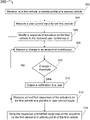
- a vehicle profile of a second vehicle is received at a first vehicle.
- the vehicle profile of the second vehicle can be received from a locally attached media storage device or over a network connection, such as over the internet.
- the vehicle profile of the second vehicle correlates measured responses of one or more actuators on the second vehicle to measured user control inputs on the second vehicle.
- the second vehicle is a specific single vehicle. In other words, the correlation for measured responses of the actuators to user control inputs is for a single vehicle, such as another vehicle driven by the user of the first vehicle.
- the second vehicle represents an average vehicle based on measured responses of actuators on each of a plurality of vehicles to corresponding measured user control inputs on each of the plurality of vehicles.
- the vehicle profile of the second vehicle in such embodiments is a crowdsourced vehicle profile as discussed above.
- a user control input for the first vehicle is received.
- a user control input can be received from a steering wheel, a brake pedal, an acceleration pedal, a horn, etc.
- a response of one or more actuators on the first vehicle to the received user control input is modified based on the received vehicle profile of the second vehicle such that the one or more actuators on the first vehicle mimic the one or more actuators on the second vehicle, as discussed above.
- the processor causes the actuators on the first vehicle to respond to the received user control input in similar manner to the actuators on the second vehicle. For example, pushing an acceleration pedal half way to the floor results in approximately the same acceleration in approximately the same amount of time on the first vehicle as on the second vehicle, in some embodiments.
- Modifying the response of the one or more actuators can include, in some embodiments, monitoring a response of the actuators to the user control input via sensors and adjusting the response until the monitored response matches the expected response from the second vehicle profile.
- the received vehicle profile is used to detect maintenance needs.
- the processor monitors a change in an amount of modification applied to the actuators of the first vehicle to mimic the actuators of the second vehicle, at block 308 .
- the processor compares the monitored change to a predetermined threshold. If it is determined that the change does not exceed the threshold, the method 300 can return to block 308 . If it is determined that the change does exceed the threshold, a notification of the maintenance need is output to the user. For example, as described above, an audio notification and/or a visual notification can be output to the user at block 312 , in some embodiments.
- the processor is configured to generate a vehicle profile for the first vehicle.
- the processor measures, via one or more sensors, unmodified responses of the actuators on the first vehicle to a plurality of user control inputs for the first vehicle, at block 314 .
- the unmodified responses can be measured prior to receiving the vehicle profile of the second vehicle in some embodiments.
- the user can select to not use the vehicle profile of the second vehicle.
- the native/original responsiveness of the actuators on the first vehicle is used.
- the processor can monitor the unmodified or native responses of the actuators on the first vehicle.
- monitoring the unmodified responses can include monitoring road conditions (e.g. road incline, wet road, bumpy road, etc.) and weather conditions (e.g. temperature, rain, snow, etc.), in some embodiments.
- the measured unmodified responses are saved or stored in a vehicle profile for the first vehicle.
- the vehicle profile of the first vehicle correlates the native responsiveness of the actuators of the first vehicle to a plurality of user control inputs.
- the stored vehicle profile for the first vehicle correlates the monitored road and/or weather conditions with the measured responses of the actuators and the measured user control inputs.
- the second vehicle profile can also include correlations with road and/or weather conditions. Additionally, as discussed above, the second vehicle profile can include data regarding the age and condition of the second vehicle.
- the method 300 enables a first vehicle to mimic the responsiveness of a second different vehicle under different conditions (e.g. road and/or weather conditions) as discussed above. This enables a driver to more easily switch between vehicles and have an expected driving experience with little need to adapt to the responsiveness of a different vehicle.
- the method can also help in detecting maintenance and repair issues, as discussed above.
- the present invention may be a system, a method, and/or a computer program product at any possible technical detail level of integration
- the computer program product may include a computer readable storage medium (or media) having computer readable program instructions thereon for causing a processor to carry out aspects of the present invention
- the computer readable storage medium can be a tangible device that can retain and store instructions for use by an instruction execution device.
- the computer readable storage medium may be, for example, but is not limited to, an electronic storage device, a magnetic storage device, an optical storage device, an electromagnetic storage device, a semiconductor storage device, or any suitable combination of the foregoing.
- a non-exhaustive list of more specific examples of the computer readable storage medium includes the following: a portable computer diskette, a hard disk, a random access memory (RAM), a read-only memory (ROM), an erasable programmable read-only memory (EPROM or Flash memory), a static random access memory (SRAM), a portable compact disc read-only memory (CD-ROM), a digital versatile disk (DVD), a memory stick, a floppy disk, a mechanically encoded device such as punch-cards or raised structures in a groove having instructions recorded thereon, and any suitable combination of the foregoing.
- RAM random access memory
- ROM read-only memory
- EPROM or Flash memory erasable programmable read-only memory
- SRAM static random access memory
- CD-ROM compact disc read-only memory
- DVD digital versatile disk
- memory stick a floppy disk
- a mechanically encoded device such as punch-cards or raised structures in a groove having instructions recorded thereon
- a computer readable storage medium is not to be construed as being transitory signals per se, such as radio waves or other freely propagating electromagnetic waves, electromagnetic waves propagating through a waveguide or other transmission media (e.g., light pulses passing through a fiber-optic cable), or electrical signals transmitted through a wire.
- Computer readable program instructions described herein can be downloaded to respective computing/processing devices from a computer readable storage medium or to an external computer or external storage device via a network, for example, the Internet, a local area network, a wide area network and/or a wireless network.
- the network may comprise copper transmission cables, optical transmission fibers, wireless transmission, routers, firewalls, switches, gateway computers and/or edge servers.
- a network adapter card or network interface in each computing/processing device receives computer readable program instructions from the network and forwards the computer readable program instructions for storage in a computer readable storage medium within the respective computing/processing device.
- Computer readable program instructions for carrying out operations of the present invention may be assembler instructions, instruction-set-architecture (ISA) instructions, machine instructions, machine dependent instructions, microcode, firmware instructions, state-setting data, configuration data for integrated circuitry, or either source code or object code written in any combination of one or more programming languages, including an object oriented programming language such as Smalltalk, C++, or the like, and procedural programming languages, such as the “C” programming language or similar programming languages.
- the computer readable program instructions may execute entirely on the user's computer, partly on the user's computer, as a stand-alone software package, partly on the user's computer and partly on a remote computer or entirely on the remote computer or server.
- the remote computer may be connected to the user's computer through any type of network, including a local area network (LAN) or a wide area network (WAN), or the connection may be made to an external computer (for example, through the Internet using an Internet Service Provider).
- electronic circuitry including, for example, programmable logic circuitry, field-programmable gate arrays (FPGA), or programmable logic arrays (PLA) may execute the computer readable program instructions by utilizing state information of the computer readable program instructions to personalize the electronic circuitry, in order to perform aspects of the present invention.
- These computer readable program instructions may be provided to a processor of a computer, or other programmable data processing apparatus to produce a machine, such that the instructions, which execute via the processor of the computer or other programmable data processing apparatus, create means for implementing the functions/acts specified in the flowchart and/or block diagram block or blocks.
- These computer readable program instructions may also be stored in a computer readable storage medium that can direct a computer, a programmable data processing apparatus, and/or other devices to function in a particular manner, such that the computer readable storage medium having instructions stored therein comprises an article of manufacture including instructions which implement aspects of the function/act specified in the flowchart and/or block diagram block or blocks.
- the computer readable program instructions may also be loaded onto a computer, other programmable data processing apparatus, or other device to cause a series of operational steps to be performed on the computer, other programmable apparatus or other device to produce a computer implemented process, such that the instructions which execute on the computer, other programmable apparatus, or other device implement the functions/acts specified in the flowchart and/or block diagram block or blocks.
- each block in the flowchart or block diagrams may represent a module, segment, or portion of instructions, which comprises one or more executable instructions for implementing the specified logical function(s).
- the functions noted in the blocks may occur out of the order noted in the Figures.
- two blocks shown in succession may, in fact, be accomplished as one step, executed concurrently, substantially concurrently, in a partially or wholly temporally overlapping manner, or the blocks may sometimes be executed in the reverse order, depending upon the functionality involved.
Abstract
Description
Claims (20)
Priority Applications (1)
| Application Number | Priority Date | Filing Date | Title |
|---|---|---|---|
| US16/568,958 US11459028B2 (en) | 2019-09-12 | 2019-09-12 | Adjusting vehicle sensitivity |
Applications Claiming Priority (1)
| Application Number | Priority Date | Filing Date | Title |
|---|---|---|---|
| US16/568,958 US11459028B2 (en) | 2019-09-12 | 2019-09-12 | Adjusting vehicle sensitivity |
Publications (2)
| Publication Number | Publication Date |
|---|---|
| US20210078629A1 US20210078629A1 (en) | 2021-03-18 |
| US11459028B2 true US11459028B2 (en) | 2022-10-04 |
Family
ID=74869289
Family Applications (1)
| Application Number | Title | Priority Date | Filing Date |
|---|---|---|---|
| US16/568,958 Active 2040-07-02 US11459028B2 (en) | 2019-09-12 | 2019-09-12 | Adjusting vehicle sensitivity |
Country Status (1)
| Country | Link |
|---|---|
| US (1) | US11459028B2 (en) |
Families Citing this family (4)
| Publication number | Priority date | Publication date | Assignee | Title |
|---|---|---|---|---|
| US11710097B2 (en) | 2019-03-22 | 2023-07-25 | BlueOwl, LLC | Systems and methods for obtaining incident information to reduce fraud |
| US11388351B1 (en) | 2019-10-29 | 2022-07-12 | BlueOwl, LLC | Systems and methods for gate-based vehicle image capture |
| US11417208B1 (en) * | 2019-10-29 | 2022-08-16 | BlueOwl, LLC | Systems and methods for fraud prevention based on video analytics |
| US20230231916A1 (en) * | 2022-01-18 | 2023-07-20 | Ford Global Technologies, Llc | Vehicle operation for providing attribute data |
Citations (37)
| Publication number | Priority date | Publication date | Assignee | Title |
|---|---|---|---|---|
| US20100087987A1 (en) | 2008-10-08 | 2010-04-08 | Gm Global Technoloogy Operations, Inc. | Apparatus and Method for Vehicle Driver Recognition and Customization Using Onboard Vehicle System Settings |
| US8260515B2 (en) | 2008-07-24 | 2012-09-04 | GM Global Technology Operations LLC | Adaptive vehicle control system with driving style recognition |
| US8352112B2 (en) * | 2009-04-06 | 2013-01-08 | GM Global Technology Operations LLC | Autonomous vehicle management |
| US8862384B2 (en) * | 2008-04-30 | 2014-10-14 | Continental Teves Ag & Co. Ohg | Self-learning map on the basis of environment sensors |
| DE102013016488A1 (en) | 2013-10-02 | 2015-04-02 | Audi Ag | Motor vehicle and method for controlling a motor vehicle |
| US9073555B2 (en) | 2012-01-26 | 2015-07-07 | GM Global Technology Operations LLC | Controlling operation of a vehicle based on parameters learned during driver's operation of another vehicle |
| US9117371B2 (en) * | 2012-06-22 | 2015-08-25 | Harman International Industries, Inc. | Mobile autonomous surveillance |
| US20150254781A1 (en) * | 2013-10-18 | 2015-09-10 | State Farm Mutual Automobile Insurance Company | Synchronization of vehicle sensor information |
| US20150266468A1 (en) * | 2014-03-19 | 2015-09-24 | Hyundai Motor Company | Hydraulic pressure instruction-learning apparatus for hybrid vehicle and method using the same |
| US20150291146A1 (en) | 2014-04-15 | 2015-10-15 | Ford Global Technologies, Llc | Driving scenario prediction and automatic vehicle setting adjustment |
| US9176924B2 (en) * | 2011-11-16 | 2015-11-03 | Autoconnect Holdings Llc | Method and system for vehicle data collection |
| US20160026182A1 (en) | 2014-07-25 | 2016-01-28 | Here Global B.V. | Personalized Driving of Autonomously Driven Vehicles |
| US9288270B1 (en) | 2011-04-22 | 2016-03-15 | Angel A. Penilla | Systems for learning user preferences and generating recommendations to make settings at connected vehicles and interfacing with cloud systems |
| SE1550389A1 (en) * | 2015-03-31 | 2016-10-01 | Scania Cv Ab | A method and a control unit for determining a set of velocity profiles for a platoon of grouped vehicles |
| US20170021764A1 (en) * | 2013-12-31 | 2017-01-26 | Hartford Fire Insurance Company | Electronics for remotely monitoring and controlling a vehicle |
| US20170046885A1 (en) | 2013-10-22 | 2017-02-16 | At&T Intellectual Property I, L.P. | Crowd sourced optimization of vehicle performance based on cloud based data |
| US20170243485A1 (en) * | 2012-04-24 | 2017-08-24 | Zetta Research and Development LLC, ForC series | V2v safety system using learned signal timing |
| WO2017141161A1 (en) | 2016-02-17 | 2017-08-24 | Uber Technologies, Inc. | Network computer system for analyzing driving actions of drivers on road segments of a geographic region |
| US9754325B1 (en) * | 2014-05-20 | 2017-09-05 | State Farm Mutual Automobile Insurance Company | Autonomous vehicle operation feature monitoring and evaluation of effectiveness |
| US20170278390A1 (en) * | 2014-10-10 | 2017-09-28 | Continental Teves Ag & Co. Ohg | A METHOD FOR OPERATING A CENTRAL SERVER AND A METHOD FOR HANDLING A CONTROL CARD (as amended) |
| CN107415871A (en) | 2016-04-26 | 2017-12-01 | 谷歌公司 | Mass-rent vehicle, which is set, to be recommended |
| US20180053102A1 (en) | 2016-08-16 | 2018-02-22 | Toyota Jidosha Kabushiki Kaisha | Individualized Adaptation of Driver Action Prediction Models |
| US9921581B2 (en) * | 2016-01-04 | 2018-03-20 | Ford Global Technologies, Llc | Autonomous vehicle emergency operating mode |
| US9946531B1 (en) * | 2014-11-13 | 2018-04-17 | State Farm Mutual Automobile Insurance Company | Autonomous vehicle software version assessment |
| US20180141568A1 (en) * | 2016-11-21 | 2018-05-24 | Nio Usa, Inc. | Vehicle autonomy level selection based on user context |
| US20180233040A1 (en) * | 2014-10-10 | 2018-08-16 | Continental Teves Ag & Co. Ohg | Method for handling a control card |
| US20190009785A1 (en) * | 2017-07-05 | 2019-01-10 | Panasonic Intellectual Property Management Co., Ltd. | System and method for detecting bullying of autonomous vehicles while driving |
| US10217358B2 (en) * | 2014-10-10 | 2019-02-26 | Continental Teves Ag & Co. Ohg | Method for handling a control card |
| US20190243381A1 (en) * | 2018-02-02 | 2019-08-08 | Continental Teves Ag & Co. Ohg | Method and device for the decentralized cooperative coordination of vehicles |
| US20190354101A1 (en) * | 2018-05-21 | 2019-11-21 | Cummins Inc. | Adjustment of autonomous vehicle control authority |
| US20200042017A1 (en) * | 2018-07-31 | 2020-02-06 | Honda Motor Co., Ltd. | System and method for shared autonomy through cooperative sensing |
| US20200219070A1 (en) * | 2019-01-07 | 2020-07-09 | Ottopia Technologies Ltd. | Servicing of autonomous vehicles |
| US10719886B1 (en) * | 2014-05-20 | 2020-07-21 | State Farm Mutual Automobile Insurance Company | Accident fault determination for autonomous vehicles |
| US20200312155A1 (en) * | 2018-07-31 | 2020-10-01 | Honda Motor Co., Ltd. | Systems and methods for swarm action |
| US11017553B2 (en) * | 2018-05-30 | 2021-05-25 | Nec Corporation | Information processing system |
| US11024167B2 (en) * | 2017-12-26 | 2021-06-01 | Toyota Jidosha Kabushiki Kaisha | Information collection system and information collection apparatus |
| US11036370B2 (en) * | 2018-09-25 | 2021-06-15 | Intel Corporation | Computer-assisted or autonomous driving vehicles social network |
-
2019
- 2019-09-12 US US16/568,958 patent/US11459028B2/en active Active
Patent Citations (42)
| Publication number | Priority date | Publication date | Assignee | Title |
|---|---|---|---|---|
| US8862384B2 (en) * | 2008-04-30 | 2014-10-14 | Continental Teves Ag & Co. Ohg | Self-learning map on the basis of environment sensors |
| US8260515B2 (en) | 2008-07-24 | 2012-09-04 | GM Global Technology Operations LLC | Adaptive vehicle control system with driving style recognition |
| US20100087987A1 (en) | 2008-10-08 | 2010-04-08 | Gm Global Technoloogy Operations, Inc. | Apparatus and Method for Vehicle Driver Recognition and Customization Using Onboard Vehicle System Settings |
| US8352112B2 (en) * | 2009-04-06 | 2013-01-08 | GM Global Technology Operations LLC | Autonomous vehicle management |
| US9288270B1 (en) | 2011-04-22 | 2016-03-15 | Angel A. Penilla | Systems for learning user preferences and generating recommendations to make settings at connected vehicles and interfacing with cloud systems |
| US9176924B2 (en) * | 2011-11-16 | 2015-11-03 | Autoconnect Holdings Llc | Method and system for vehicle data collection |
| US9073555B2 (en) | 2012-01-26 | 2015-07-07 | GM Global Technology Operations LLC | Controlling operation of a vehicle based on parameters learned during driver's operation of another vehicle |
| US20170243485A1 (en) * | 2012-04-24 | 2017-08-24 | Zetta Research and Development LLC, ForC series | V2v safety system using learned signal timing |
| US9117371B2 (en) * | 2012-06-22 | 2015-08-25 | Harman International Industries, Inc. | Mobile autonomous surveillance |
| DE102013016488A1 (en) | 2013-10-02 | 2015-04-02 | Audi Ag | Motor vehicle and method for controlling a motor vehicle |
| US20150254781A1 (en) * | 2013-10-18 | 2015-09-10 | State Farm Mutual Automobile Insurance Company | Synchronization of vehicle sensor information |
| US20170046885A1 (en) | 2013-10-22 | 2017-02-16 | At&T Intellectual Property I, L.P. | Crowd sourced optimization of vehicle performance based on cloud based data |
| US10023114B2 (en) * | 2013-12-31 | 2018-07-17 | Hartford Fire Insurance Company | Electronics for remotely monitoring and controlling a vehicle |
| US10399493B2 (en) * | 2013-12-31 | 2019-09-03 | Hartford Fire Insurance Company | Electronics for remotely monitoring and controlling a vehicle |
| US20170021764A1 (en) * | 2013-12-31 | 2017-01-26 | Hartford Fire Insurance Company | Electronics for remotely monitoring and controlling a vehicle |
| US20180339653A1 (en) * | 2013-12-31 | 2018-11-29 | Hartford Fire Insurance Company | Electronics for remotely monitoring and controlling a vehicle |
| US20150266468A1 (en) * | 2014-03-19 | 2015-09-24 | Hyundai Motor Company | Hydraulic pressure instruction-learning apparatus for hybrid vehicle and method using the same |
| US20150291146A1 (en) | 2014-04-15 | 2015-10-15 | Ford Global Technologies, Llc | Driving scenario prediction and automatic vehicle setting adjustment |
| US10719886B1 (en) * | 2014-05-20 | 2020-07-21 | State Farm Mutual Automobile Insurance Company | Accident fault determination for autonomous vehicles |
| US9754325B1 (en) * | 2014-05-20 | 2017-09-05 | State Farm Mutual Automobile Insurance Company | Autonomous vehicle operation feature monitoring and evaluation of effectiveness |
| US20160026182A1 (en) | 2014-07-25 | 2016-01-28 | Here Global B.V. | Personalized Driving of Autonomously Driven Vehicles |
| US20170278390A1 (en) * | 2014-10-10 | 2017-09-28 | Continental Teves Ag & Co. Ohg | A METHOD FOR OPERATING A CENTRAL SERVER AND A METHOD FOR HANDLING A CONTROL CARD (as amended) |
| US20180233040A1 (en) * | 2014-10-10 | 2018-08-16 | Continental Teves Ag & Co. Ohg | Method for handling a control card |
| US10217358B2 (en) * | 2014-10-10 | 2019-02-26 | Continental Teves Ag & Co. Ohg | Method for handling a control card |
| US9946531B1 (en) * | 2014-11-13 | 2018-04-17 | State Farm Mutual Automobile Insurance Company | Autonomous vehicle software version assessment |
| SE538817C2 (en) * | 2015-03-31 | 2016-12-13 | Scania Cv Ab | A method and a control unit for determining a set of velocity profiles for a platoon of grouped vehicles |
| SE1550389A1 (en) * | 2015-03-31 | 2016-10-01 | Scania Cv Ab | A method and a control unit for determining a set of velocity profiles for a platoon of grouped vehicles |
| US9921581B2 (en) * | 2016-01-04 | 2018-03-20 | Ford Global Technologies, Llc | Autonomous vehicle emergency operating mode |
| WO2017141161A1 (en) | 2016-02-17 | 2017-08-24 | Uber Technologies, Inc. | Network computer system for analyzing driving actions of drivers on road segments of a geographic region |
| CN107415871A (en) | 2016-04-26 | 2017-12-01 | 谷歌公司 | Mass-rent vehicle, which is set, to be recommended |
| US20180053102A1 (en) | 2016-08-16 | 2018-02-22 | Toyota Jidosha Kabushiki Kaisha | Individualized Adaptation of Driver Action Prediction Models |
| US20180141568A1 (en) * | 2016-11-21 | 2018-05-24 | Nio Usa, Inc. | Vehicle autonomy level selection based on user context |
| US20190009785A1 (en) * | 2017-07-05 | 2019-01-10 | Panasonic Intellectual Property Management Co., Ltd. | System and method for detecting bullying of autonomous vehicles while driving |
| US11024167B2 (en) * | 2017-12-26 | 2021-06-01 | Toyota Jidosha Kabushiki Kaisha | Information collection system and information collection apparatus |
| US20190243381A1 (en) * | 2018-02-02 | 2019-08-08 | Continental Teves Ag & Co. Ohg | Method and device for the decentralized cooperative coordination of vehicles |
| US20190354101A1 (en) * | 2018-05-21 | 2019-11-21 | Cummins Inc. | Adjustment of autonomous vehicle control authority |
| US11017553B2 (en) * | 2018-05-30 | 2021-05-25 | Nec Corporation | Information processing system |
| US20200312155A1 (en) * | 2018-07-31 | 2020-10-01 | Honda Motor Co., Ltd. | Systems and methods for swarm action |
| US20200042017A1 (en) * | 2018-07-31 | 2020-02-06 | Honda Motor Co., Ltd. | System and method for shared autonomy through cooperative sensing |
| US11163317B2 (en) * | 2018-07-31 | 2021-11-02 | Honda Motor Co., Ltd. | System and method for shared autonomy through cooperative sensing |
| US11036370B2 (en) * | 2018-09-25 | 2021-06-15 | Intel Corporation | Computer-assisted or autonomous driving vehicles social network |
| US20200219070A1 (en) * | 2019-01-07 | 2020-07-09 | Ottopia Technologies Ltd. | Servicing of autonomous vehicles |
Non-Patent Citations (11)
| Title |
|---|
| D. Jia, K. Lu, J. Wang, X. Zhang and X. Shen, "A Survey on Platoon-Based Vehicular Cyber-Physical Systems," in IEEE Comm. Surveys & Tutorials, vol. 18, No. 1, pp. 263-284, Firstquarter2016, doi: 10.1109/COMST.2015.2410831. (Year: 2016). * |
| D. Perez et al., "Solving the Physical Traveling Salesman Problem: Tree Search and Macro Actions," in IEEE Transactions on Computational Intelligence and AI in Games, vol. 6, No. 1, pp. 31-45, Mar. 2014, doi: 10.1109/TCIAIG.2013.2263884 (Year: 2014). * |
| D. Perez, P. Rohlfshagen, and S. Lucas, "Monte Carlo tree search: Long term versus short term planning," in Proc. IEEE Conf. Comput. Intell.Games, 2012, pp. 219-226. (Year: 2012). * |
| E. J. Powley, D. Whitehouse, and P. I. Cowling, "Monte Carlo tree search with macro-actions and heuristic route planning for the physical travelling salesman problem," in Proc. IEEE Conf. Comput. Intell. Games, 2012, pp. 234-241 (Year: 2012). * |
| K. Yu et al., "Model Predictive Control for Hybrid Electric Vehicle Platooning Using Slope Information," in IEEE Transactions on Intelligent Transportation Systems, vol. 17, No. 7, pp. 1894-1909, Jul. 2016, doi: 10.1109/TITS.2015.2513766. (Year: 2016). * |
| L. Alouache, N. Nguyen, M. Aliouat and R. Chelouah, "Toward a hybrid SDN architecture for V2V communication in IoV environment," 2018 Fifth International Conference on Software Defined Systems (SDS), 2018, pp. 93-99, doi: 10.1109/SDS.2018.8370428. * |
| S. Wei, Y. Zou, X. Zhang, T. Zhang and X. Li, "An Integrated Longitudinal and Lateral Vehicle Following Control System With Radar and Vehicle-to-Vehicle Communication," in IEEE Transactions on Vehicular Technology, vol. 68, No. 2, pp. 1116-1127, Feb. 2019, doi: 10.1109/TVT.2018.2890418. * |
| V. Milanés, S. E. Shladover, J. Spring, C. Nowakowski, H. Kawazoe and M. Nakamura, "Cooperative Adaptive Cruise Control in Real Traffic Situations," in IEEE Transactions on Intelligent Transportation Systems, vol. 15, No. 1, pp. 296-305, Feb. 2014, doi: 10.1109/TITS.2013.2278494. (Year: 2014). * |
| V. Turri, B. Besselinkand K. H. Johansson, "Cooperative Look-Ahead Control for Fuel-Efficient and Safe Heavy-Duty Vehicle Platooning," in IEEE Transactions on Control Systems Technology, vol. 25, No. 1, pp. 12-28, Jan. 2017, doi: 10.1109/TCST.2016.2542044. (Year: 2017). * |
| Vladimir vUkadinovic et al. "3GPP C-V2X and IEEE 802.11 p for Vehicle-to-Vehicle communications in highway platooning scenarios", Available online Mar. 15, 2018. * |
| Wang et al., "Modeling and Recognizing Driver Behavior Based on Driving Data: A Survey," Mathematical Problems in Engineering, vol. 2014, Article ID 245641, Feb. 10, 2014, 20 pages. <https://www.hindawi.com/journals/mpe/2014/245641/>. |
Also Published As
| Publication number | Publication date |
|---|---|
| US20210078629A1 (en) | 2021-03-18 |
Similar Documents
| Publication | Publication Date | Title |
|---|---|---|
| US11459028B2 (en) | Adjusting vehicle sensitivity | |
| US11250648B2 (en) | Predictive maintenance of automotive transmission | |
| US11531339B2 (en) | Monitoring of drive by wire sensors in vehicles | |
| KR102048646B1 (en) | Combined method with physical modeling and machine learning to simulate autonomous vehicle movement | |
| US10809726B2 (en) | Sideslip compensated control method for autonomous vehicles | |
| US11586194B2 (en) | Storage and access of neural network models of automotive predictive maintenance | |
| US20210055907A1 (en) | Intelligent audio control in vehicles | |
| US20210049445A1 (en) | Predictive maintenance of automotive tires | |
| CN109017810B (en) | Vehicle chassis fault detection method and device, vehicle-mounted equipment and storage medium | |
| US11704554B2 (en) | Automated training data extraction method for dynamic models for autonomous driving vehicles | |
| US11046293B2 (en) | Facilitation of automatic adjustment of a braking system | |
| KR20180052673A (en) | System delay estimation method for autonomous vehicle control | |
| US20190248379A1 (en) | Systems and methods for identifying first route to destination as involving less human driving of vehicle than second route to destination | |
| JP2019034721A (en) | Method for determining friction value for contact between tire of vehicle and roadway, and method for controlling vehicle function of vehicle | |
| CN107042827A (en) | System and method for the Dynamic Announce of vehicle | |
| US11904853B2 (en) | Apparatus for preventing vehicle collision and method thereof | |
| US20230077159A1 (en) | Responding to a signal indicating that an autonomous driving feature has been overridden by alerting plural vehicles | |
| JP2020190778A (en) | Information processing device, information processing method, and information processing program | |
| JP2020035435A (en) | Vehicle operation control method, vehicle operation control device, computer equipment, computer-readable storage medium, and computer program | |
| US11505200B2 (en) | System and method for voice command vehicle systems control | |
| FR3079954A1 (en) | PREDICTIVE AUTOMATIC LEARNING FOR PREDICTING A FUTURE SPEED OF A MOTOR VEHICLE MOVING ON A ROAD | |
| US8165744B2 (en) | Methods, program products, and systems for controlling for improper installation of vehicle sensors | |
| US11562237B2 (en) | Processing of overwhelming stimuli in vehicle data recorders | |
| CN110737206A (en) | method, device and storage medium for quantifying driving feeling based on vehicle body dynamics | |
| CN114325711A (en) | Vehicle cliff and crack detection system and method |
Legal Events
| Date | Code | Title | Description |
|---|---|---|---|
| AS | Assignment |
Owner name: INTERNATIONAL BUSINESS MACHINES CORPORATION, NEW YORK Free format text: ASSIGNMENT OF ASSIGNORS INTEREST;ASSIGNORS:BOSS, GREGORY J.;BENDER, MICHAEL;FOX, JEREMY R.;REEL/FRAME:050359/0582 Effective date: 20190909 |
|
| FEPP | Fee payment procedure |
Free format text: ENTITY STATUS SET TO UNDISCOUNTED (ORIGINAL EVENT CODE: BIG.); ENTITY STATUS OF PATENT OWNER: LARGE ENTITY |
|
| STPP | Information on status: patent application and granting procedure in general |
Free format text: DOCKETED NEW CASE - READY FOR EXAMINATION |
|
| STPP | Information on status: patent application and granting procedure in general |
Free format text: NON FINAL ACTION MAILED |
|
| STPP | Information on status: patent application and granting procedure in general |
Free format text: RESPONSE TO NON-FINAL OFFICE ACTION ENTERED AND FORWARDED TO EXAMINER |
|
| AS | Assignment |
Owner name: KYNDRYL, INC., NEW YORK Free format text: ASSIGNMENT OF ASSIGNORS INTEREST;ASSIGNOR:INTERNATIONAL BUSINESS MACHINES CORPORATION;REEL/FRAME:058213/0912 Effective date: 20211118 |
|
| STPP | Information on status: patent application and granting procedure in general |
Free format text: FINAL REJECTION MAILED |
|
| STPP | Information on status: patent application and granting procedure in general |
Free format text: RESPONSE AFTER FINAL ACTION FORWARDED TO EXAMINER |
|
| STPP | Information on status: patent application and granting procedure in general |
Free format text: ADVISORY ACTION MAILED |
|
| STPP | Information on status: patent application and granting procedure in general |
Free format text: DOCKETED NEW CASE - READY FOR EXAMINATION |
|
| STPP | Information on status: patent application and granting procedure in general |
Free format text: NON FINAL ACTION MAILED |
|
| STPP | Information on status: patent application and granting procedure in general |
Free format text: RESPONSE TO NON-FINAL OFFICE ACTION ENTERED AND FORWARDED TO EXAMINER |
|
| STPP | Information on status: patent application and granting procedure in general |
Free format text: NOTICE OF ALLOWANCE MAILED -- APPLICATION RECEIVED IN OFFICE OF PUBLICATIONS |
|
| STPP | Information on status: patent application and granting procedure in general |
Free format text: PUBLICATIONS -- ISSUE FEE PAYMENT VERIFIED |
|
| STCF | Information on status: patent grant |
Free format text: PATENTED CASE |