US11458917B2 - Sensor attachment structure - Google Patents
Sensor attachment structure Download PDFInfo
- Publication number
- US11458917B2 US11458917B2 US16/846,700 US202016846700A US11458917B2 US 11458917 B2 US11458917 B2 US 11458917B2 US 202016846700 A US202016846700 A US 202016846700A US 11458917 B2 US11458917 B2 US 11458917B2
- Authority
- US
- United States
- Prior art keywords
- sensor
- surrounding information
- attachment
- vehicle
- attachment recess
- Prior art date
- Legal status (The legal status is an assumption and is not a legal conclusion. Google has not performed a legal analysis and makes no representation as to the accuracy of the status listed.)
- Active, expires
Links
Images


Classifications
-
- B—PERFORMING OPERATIONS; TRANSPORTING
- B60—VEHICLES IN GENERAL
- B60R—VEHICLES, VEHICLE FITTINGS, OR VEHICLE PARTS, NOT OTHERWISE PROVIDED FOR
- B60R11/00—Arrangements for holding or mounting articles, not otherwise provided for
-
- B—PERFORMING OPERATIONS; TRANSPORTING
- B60—VEHICLES IN GENERAL
- B60R—VEHICLES, VEHICLE FITTINGS, OR VEHICLE PARTS, NOT OTHERWISE PROVIDED FOR
- B60R19/00—Wheel guards; Radiator guards, e.g. grilles; Obstruction removers; Fittings damping bouncing force in collisions
- B60R19/02—Bumpers, i.e. impact receiving or absorbing members for protecting vehicles or fending off blows from other vehicles or objects
- B60R19/48—Bumpers, i.e. impact receiving or absorbing members for protecting vehicles or fending off blows from other vehicles or objects combined with, or convertible into, other devices or objects, e.g. bumpers combined with road brushes, bumpers convertible into beds
- B60R19/483—Bumpers, i.e. impact receiving or absorbing members for protecting vehicles or fending off blows from other vehicles or objects combined with, or convertible into, other devices or objects, e.g. bumpers combined with road brushes, bumpers convertible into beds with obstacle sensors of electric or electronic type
-
- B—PERFORMING OPERATIONS; TRANSPORTING
- B60—VEHICLES IN GENERAL
- B60R—VEHICLES, VEHICLE FITTINGS, OR VEHICLE PARTS, NOT OTHERWISE PROVIDED FOR
- B60R13/00—Elements for body-finishing, identifying, or decorating; Arrangements or adaptations for advertising purposes
- B60R13/04—External Ornamental or guard strips; Ornamental inscriptive devices thereon
-
- B—PERFORMING OPERATIONS; TRANSPORTING
- B60—VEHICLES IN GENERAL
- B60R—VEHICLES, VEHICLE FITTINGS, OR VEHICLE PARTS, NOT OTHERWISE PROVIDED FOR
- B60R11/00—Arrangements for holding or mounting articles, not otherwise provided for
- B60R11/04—Mounting of cameras operative during drive; Arrangement of controls thereof relative to the vehicle
-
- B—PERFORMING OPERATIONS; TRANSPORTING
- B60—VEHICLES IN GENERAL
- B60R—VEHICLES, VEHICLE FITTINGS, OR VEHICLE PARTS, NOT OTHERWISE PROVIDED FOR
- B60R11/00—Arrangements for holding or mounting articles, not otherwise provided for
- B60R2011/0001—Arrangements for holding or mounting articles, not otherwise provided for characterised by position
- B60R2011/004—Arrangements for holding or mounting articles, not otherwise provided for characterised by position outside the vehicle
-
- B—PERFORMING OPERATIONS; TRANSPORTING
- B60—VEHICLES IN GENERAL
- B60R—VEHICLES, VEHICLE FITTINGS, OR VEHICLE PARTS, NOT OTHERWISE PROVIDED FOR
- B60R11/00—Arrangements for holding or mounting articles, not otherwise provided for
- B60R2011/0042—Arrangements for holding or mounting articles, not otherwise provided for characterised by mounting means
-
- G—PHYSICS
- G01—MEASURING; TESTING
- G01S—RADIO DIRECTION-FINDING; RADIO NAVIGATION; DETERMINING DISTANCE OR VELOCITY BY USE OF RADIO WAVES; LOCATING OR PRESENCE-DETECTING BY USE OF THE REFLECTION OR RERADIATION OF RADIO WAVES; ANALOGOUS ARRANGEMENTS USING OTHER WAVES
- G01S13/00—Systems using the reflection or reradiation of radio waves, e.g. radar systems; Analogous systems using reflection or reradiation of waves whose nature or wavelength is irrelevant or unspecified
- G01S13/88—Radar or analogous systems specially adapted for specific applications
- G01S13/93—Radar or analogous systems specially adapted for specific applications for anti-collision purposes
- G01S13/931—Radar or analogous systems specially adapted for specific applications for anti-collision purposes of land vehicles
- G01S2013/9327—Sensor installation details
- G01S2013/93274—Sensor installation details on the side of the vehicles
Definitions
- the present specification discloses a structure in which a surrounding information sensor that detects surrounding information of a vehicle is attached to an exterior panel of the vehicle.
- a vehicle having a driving assistance function or an autonomous driving function in which a part or all of a dynamic driving task of the vehicle is automatically performed on the vehicle side has been known.
- a vehicle usually has a surrounding information sensor that detects surrounding information of the vehicle.
- the surrounding information sensor may be, for example, a camera that captures an image of the periphery of the vehicle, a laser sensor that detects an object using radio waves, or an optical sensor that detects an object using light.
- a surrounding information sensor is attached to an exterior panel such as a fender panel.
- JP 2017-193223 A discloses a technique of attaching a surrounding information sensor to the inside of a fender panel in a vehicle-width direction.
- a bracket is disposed inside the fender panel in the vehicle-width direction (inside the vehicle), and the surrounding information sensor is attached to the bracket.
- the present specification discloses a sensor attachment structure capable of simplifying an operation of attaching a surrounding information sensor to an exterior panel.
- the sensor attachment structure includes: an attachment recess formed by causing a part of an exterior panel of a vehicle to be depressed toward an inside of the vehicle; a surrounding information sensor configured to detect surrounding information of the vehicle, at least a part of the surrounding information sensor being disposed further inside the vehicle than the attachment recess; an attachment member configured to attach the surrounding information sensor to the exterior panel from an outside of the vehicle; and a cover body configured to cover and hide the attachment member attached to the attachment recess, the cover body being attached to the exterior panel.
- the surrounding information sensor can be attached by an operation from the outside of the vehicle, so that the operation of attaching the sensor can be simplified.
- the attachment member attached from the outside of the vehicle is covered and hidden by the cover body, the design is not impaired.
- a panel-side opening that exposes at least a part of the surrounding information sensor may be formed in a depression direction bottom surface of the attachment recess.
- a cover-side opening that exposes at least a part of the surrounding information sensor may be formed in a portion of the cover body that faces the panel-side opening.
- a corner hole that is a through-hole may be formed in at least one corner of the attachment recess.
- one of the surrounding information sensor and the attachment recess may have a locking claw protruding toward the other, and the other of the surrounding information sensor and the attachment recess may have a locking hole into which the locking claw is inserted and caught.
- the cover body may be fastened to a depression direction bottom surface of the attachment recess by a cover clip protruding from a rear surface of the cover body.
- the cover body When the cover body is attached to the attachment recess with the cover clip protruding from the rear surface of the cover body, the cover clip is not visible from the outside of the vehicle, so that deterioration of the design of the cover clip can be suppressed.
- the operation of attaching the surrounding information sensor to the exterior panel can be simplified.
- FIG. 1 is a perspective view of a vehicle viewed from a front;
- FIG. 2 is an exploded perspective view illustrating a form of attachment of a surrounding information sensor
- FIG. 3 is a perspective view of an attachment recess
- FIG. 4 is a view of the attachment recess viewed from a side
- FIG. 5 is a perspective view of the surrounding information sensor
- FIG. 6 is a perspective view of a cover body viewed from a rear side
- FIG. 7 is a schematic cross-sectional view illustrating a form in which a surrounding information sensor is disposed inward of the attachment recess in a vehicle-width direction;
- FIG. 8 is a schematic cross-sectional view illustrating a form in which the surrounding information sensor is disposed in the attachment recess.
- FIG. 1 is a perspective view of a vehicle 10 viewed from the front.
- “Fr”, “Up”, and “R” indicate the front of the vehicle, the upper side of the vehicle, and the right side of the vehicle, respectively.
- the vehicle 10 has a driving assistance function or an autonomous driving function.
- the “driving assistance” is a function in which a part of a dynamic driving task is performed by the vehicle 10 , and means, for example, Level 1 or Level 2 defined by the Society of Automotive Engineers (SAE).
- SAE Society of Automotive Engineers
- Level 1 the vehicle 10 supports either a steering operation or acceleration/deceleration.
- Level 2 the vehicle 10 supports driving while coordinating both a steering operation and acceleration/deceleration.
- the “autonomous driving” is a function in which almost all of the dynamic driving task is performed by the vehicle 10 , and means, for example, any one of Level 3 to Level 5 defined by SAE.
- Level 3 is a driving mode in which all of the dynamic driving task is automated in a specific place such as an expressway, but an operation by a driver is needed in an emergency.
- Level 4 is a driving mode in which all of the dynamic driving task is automated solely in a specific place, and an emergency response is also automatically processed.
- Level 5 is a driving mode in which autonomous driving can be performed under almost all conditions without restriction on places and the like, and means so-called “full autonomous driving”.
- a surrounding information sensor 40 is mounted in the vehicle 10 .
- the surrounding information sensor 40 is a sensor that detects the surrounding states of the vehicle 10 .
- the surrounding information sensor 40 may be, for example, a camera that includes an image sensor (such as a CCD sensor or a CMOS sensor) and captures an image of the surroundings of the vehicle 10 .
- the surrounding information sensor 40 may be a sensor that detects an object around the vehicle by transmitting and receiving electromagnetic waves. Examples of the sensor include a millimeter wave radar using millimeter waves, an infrared laser radar using an infrared laser, and a lidar using laser light emitted in a pulse shape.
- the surrounding information sensor 40 may be a sensor that detects an object around the vehicle 10 by transmitting and receiving ultrasonic waves, for example, a clearance sonar.
- the number of surrounding information sensors 40 mounted in one vehicle 10 and the number of kinds thereof are not particularly limited as long as the number thereof is one or more and the number of kinds thereof is one or more.
- one surrounding information sensor 40 is attached to a fender panel 16 .
- the fender panel 16 forms a part of the exterior panel 14 and is a sheet metal member obtained by forming a metal panel.
- the fender panel 16 is a side surface of the vehicle 10 and is located above a front wheel 12 .
- the surrounding information sensor 40 is disposed inward of the fender panel 16 in a vehicle-width direction (inside the vehicle, the R direction in the illustrated example).
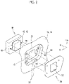
- FIG. 2 is an exploded perspective view illustrating a form of the attachment of the surrounding information sensor 40 .
- FIG. 3 is a perspective view of an attachment recess 18
- FIG. 4 is a view of the attachment recess 18 viewed from a side (R direction).
- FIG. 5 is a perspective view of the surrounding information sensor 40
- FIG. 6 is a perspective view of a cover body 50 viewed from a rear side.
- the fender panel 16 is hatched in black to clarify the positions of openings and holes.
- a part of the fender panel 16 (exterior panel 14 ) to which the surrounding information sensor 40 is attached is provided with the attachment recess 18 formed by causing the fender panel 16 to be depressed toward the inside of the vehicle (inward in the vehicle-width direction).
- the attachment recess 18 is substantially quadrangular as illustrated in FIGS. 3 and 4 .
- a substantially rectangular panel-side opening 24 is formed at the center of a depression direction bottom surface 29 of the attachment recess 18 .
- the panel-side opening 24 is provided for allowing a protruding portion 43 of a sensor main body 42 , which will be described later, to pass therethrough to expose a detection surface 44 to the outside.
- sensor fastening holes 20 are circular holes, and three sensor fastening holes 20 are formed in the periphery of the panel-side opening 24 .
- the sensor fastening hole 20 is a fastening hole for attaching the surrounding information sensor 40 to the exterior panel 14 , and is a hole into which a sensor clip 30 (see FIG. 2 ) is inserted.
- the sensor clip 30 is an attachment member for attaching the surrounding information sensor 40 to the exterior panel 14 .
- the sensor clip 30 has, for example, a wide flange and a main body shaft extending from the flange, and the main body shaft expands and contracts in a radial direction and is firmly fixed to a clip hole 46 of the surrounding information sensor 40 .
- the cover fastening holes 22 are round holes provided at locations closer to the panel-side opening 24 than the four corners of the attachment recess 18 .
- the location where each cover fastening hole 22 is formed protrudes in an island shape toward the outside of the vehicle.
- the cover fastening holes 22 are fastening hole for attaching the cover body 50 , which will be described later, to the exterior panel 14 , and are holes into which cover clips 56 (see FIG. 6 ) are inserted and engaged.
- a total of two locking holes 26 are formed respectively on both sides of the panel-side opening 24 in a horizontal direction.
- the locking holes 26 are holes into which locking claws 48 (see FIG. 5 ), which will be described later, are inserted and caught.
- one locking hole 26 has a substantially rectangular shape, and the other locking hole 26 has a keyhole shape in which a rectangle is connected to the lower side of a circle.
- the arrangement heights of the two locking holes 26 are substantially the same.
- the surrounding information sensor 40 is temporarily placed by causing the locking claws 48 to be caught in the locking holes 26 , and this will be described later.
- Corner holes 28 are further formed at the corners of the attachment recess 18 (see FIG. 3 ).
- Each corner hole 28 is a relatively large hole that spans the depression direction bottom surface 29 and a peripheral surface 27 of the attachment recess 18 .
- corner holes 28 By forming the corner holes 28 at the corners of the attachment recess 18 , surface distortion of the corners of the attachment recess 18 can be absorbed by the corner holes 28 . Accordingly, the distortion of the surface of the fender panel 16 can be reduced, and good surface quality can be secured.
- the surrounding information sensor 40 is a sensor that detects the surrounding states of the vehicle 10 .
- the surrounding information sensor 40 is disposed inward of the attachment recess 18 (exterior panel 14 ) in the vehicle-width direction and attached to the exterior panel 14 .
- the surrounding information sensor 40 is roughly divided into the sensor main body 42 and a sensor frame 45 that holds the sensor main body 42 .
- the protruding portion 43 protruding outward in the vehicle-width direction is present, and the tip end surface of the protruding portion 43 serves as the detection surface 44 that transmits and receives electromagnetic waves or ultrasonic waves for detection.
- the sensor frame 45 holds the sensor main body 42 in a state where the protruding portion 43 is exposed to the outside.
- Three clip holes 46 and two locking claws 48 are provided in a vehicle-width direction outer end surface of the sensor frame 45 .
- the clip holes 46 are provided at positions opposite to the sensor fastening holes 20 in a state where the protruding portion 43 passes through the panel-side opening 24 .
- Each clip hole 46 is a hole into which the sensor clip 30 is inserted and engaged.
- the locking claw 48 is a substantially L-shaped projection that extends outward in the vehicle-width direction from the vehicle-width direction outer end surface of the sensor frame 45 and then extends downward.
- the locking claws 48 are provided at positions substantially opposite to the locking holes 26 in the state where the protruding portion 43 passes through the panel-side opening 24 .
- the dimension of the locking claw 48 in an up-down direction is smaller than the dimension of the locking hole 26 in the up-down direction such that the locking claw 48 can pass through the locking hole 26 .
- the dimension of the locking claw 48 in the horizontal direction is smaller than the dimension of the lower end edge of the locking hole 26 in the horizontal direction such that when the locking claw 48 is inserted into the locking hole 26 , the locking claw 48 is caught in the lower end edge of the locking hole 26 and does not fall.
- the surrounding information sensor 40 Since the locking claw 48 is caught in the locking hole 26 , the surrounding information sensor 40 is temporarily placed at a predetermined height position. In a state where the surrounding information sensor 40 is temporarily placed, the sensor clips 30 are fitted into the sensor fastening holes 20 and the clip holes 46 from the outside of the vehicle, whereby the surrounding information sensor 40 is fastened to the exterior panel 14 .
- the depth of the attachment recess 18 is sufficiently larger than the height of the head of the sensor clip 30 so that the head of the sensor clip 30 does not protrude outward from the attachment recess 18 .
- the cover body 50 is a plate-like member that covers and hides the sensor clips 30 attached to the attachment recess 18 .
- the cover body 50 has an outer shape that is substantially the same as the outer shape of the attachment recess 18 , or slightly offset inward from the outer shape of the attachment recess 18 .
- a cover-side opening 52 for exposing the detection surface 44 of the surrounding information sensor 40 to the outside is formed at the center of the cover body 50 at a location directly opposite to the panel-side opening 24 .
- the outer surface of the cover body 50 is a smooth surface having no irregularities, and has almost the same texture as the outer surface of the fender panel 16 .
- the cover clip 56 stands on each of the pedestal portions 54 toward the inside in the vehicle-width direction.
- the cover clip 56 is a clip that is inserted into and engaged with the cover fastening hole 22 of the attachment recess 18 . Therefore, the cover clip 56 is provided at a position opposite to the cover fastening hole 22 .
- the height of the pedestal portion 54 is set such that the outer surface of the cover body 50 subjected to clip fastening is smoothly connected to the outer surface of the fender panel 16 in the periphery of the cover body 50 .
- the cover body 50 is fitted to the attachment recess 18 from the outside of the vehicle 10 so as to cause the cover clips 56 to be fitted into the cover fastening holes 22 , thereby being attached to the attachment recess 18 .
- the surrounding information sensor 40 is brought inside the fender panel 16 in the vehicle-width direction. Subsequently, the protruding portion 43 of the surrounding information sensor 40 is caused to pass through the panel-side opening 24 , and the locking claws 48 are caught in the locking holes 26 . When the locking claws 48 are caught in the locking holes 26 , an operator inserts the three sensor clips 30 into the sensor fastening holes 20 and the clip holes 46 from the outside of the vehicle 10 so as to be engaged.
- the fastening operation of the sensor clips 30 is an operation performed from the outside of the vehicle and thus can be performed more easily than a case where the operation is performed from the inside of the vehicle.
- the surrounding information sensor 40 is temporarily placed by the locking claws 48 , the operator can release hands from the surrounding information sensor 40 as needed. As a result, both hands can be used freely as needed, so that the operation properties of the operator can be further improved.
- the cover body 50 is fastened to the attachment recess 18 .
- the operator fits the cover body 50 into the attachment recess 18 from the outside of the vehicle 10 such that the cover clips 56 of the cover body 50 are inserted into the cover fastening holes 22 of the attachment recess 18 .
- the cover clips 56 are inserted into the cover fastening holes 22 and engaged therewith, whereby the cover body 50 is attached to the attachment recess 18 .
- the operation of fastening the cover body 50 is also an operation performed from the outside of the vehicle and thus can be performed more easily than a case where the operation is performed from the inside of the vehicle. Also, by attaching the cover body 50 , the head of the sensor clip 30 and the locking claw 48 exposed in the attachment recess 18 are covered and hidden by the cover body 50 , so that the design of the vehicle 10 is improved. On the other hand, the detection surface 44 of the surrounding information sensor 40 is exposed to the outside via the panel-side opening 24 and the cover-side opening 52 . As a result, electromagnetic waves or ultrasonic waves for detection can be transmitted and received satisfactorily, and a decrease in the accuracy of the surrounding information sensor 40 can be suppressed.
- both the surrounding information sensor 40 and the cover body 50 can be attached by access from the outside of the vehicle 10 .
- the fastening operation of the surrounding information sensor 40 and the like can be simplified.
- the heads of the clips 30 , 56 used for fastening are covered and hidden by the cover body 50 , so that deterioration of the design of the vehicle 10 can be effectively suppressed.
- FIG. 7 is a schematic cross-sectional view illustrating a form in which the surrounding information sensor 40 is disposed inward of the attachment recess 18 in the vehicle-width direction as in this example
- FIG. 8 is a schematic cross-sectional view illustrating a form in which the surrounding information sensor 40 is disposed in the attachment recess 18 .
- the surrounding information sensor 40 is disposed further inside the vehicle 10 than the attachment recess 18 as illustrated in FIG. 7 .
- FIG. 8 it is conceivable to dispose the surrounding information sensor 40 in the attachment recess 18 (further outside the vehicle than the bottom surface 29 ). Even in this case, the sensor clip 30 can be inserted from the outside of the vehicle, so that the operation properties are not much different from the case of FIG. 7 .
- a depth Lb of the attachment recess 18 needs to be larger than a thickness La of the surrounding information sensor 40 .
- the thickness La of the surrounding information sensor 40 varies depending on the kind of the sensor and the like, but is generally sufficiently larger than a head height Lc of the sensor clip 30 .
- the attachment recess 18 is formed by a drawing process.
- the depth Lb of the attachment recess 18 is large, the attachment recess 18 cannot be formed by a single drawing process, and needs to be gradually deepened by a plurality of drawing processes, resulting in an increase in the number of manufacturing processes of the exterior panel 14 .
- the depth Lb of the attachment recess 18 is excessively large, cracking of the material and surface distortion are likely to occur even when the drawing process is divided into a plurality of drawing processes, and there is concern that deterioration of the surface quality of the exterior panel 14 may be caused.
- the depth Lb of the attachment recess 18 may be greater than the head height Lc of the sensor clip 30 .
- the depth Lb of the attachment recess 18 can be reduced with the configuration of FIG. 7 .
- the number of drawing processes for forming the attachment recess 18 can be reduced.
- the surface quality of the exterior panel 14 can be kept high.
- the corner holes 28 that absorb the distortion of the surface are formed at the corners of the attachment recess 18 , the surface quality can be kept higher.
- the configuration that has been described above is merely an example, and the other configurations may be changed as long as the surrounding information sensor 40 disposed further inside the vehicle than the attachment recess 18 is attached to the exterior panel 14 from the outside of the vehicle by the attachment member and the attachment member is covered and hidden by the cover body 50 attached to the exterior panel 14 .
- the number and positions of the fastening holes 20 , 22 and the locking holes 26 may be changed as appropriate.
- the clip is used as the attachment member for attaching the surrounding information sensor 40
- another attachment member may be used.
- bolts, rivets, or the like may be used as attachment members.
- the locking claws 48 are provided in the surrounding information sensor 40 and the locking holes 26 are provided in the attachment recess 18 , this may be reversed. That is, a locking claw protruding from the bottom surface 29 of the attachment recess 18 toward the inside of the vehicle may be formed, and the surrounding information sensor 40 may be provided with a locking hole in which the locking claw is caught. In some cases, the locking claw 48 and the locking hole 26 may be omitted.
- the cover body 50 may also be attached by units other than the clip standing on the cover body 50 .
- an engagement claw that is engaged with the peripheral edge of the attachment recess 18 may be formed on the peripheral edge of the cover body 50 , and accordingly the cover body 50 may be attached to the attachment recess 18 .
- the panel-side opening 24 and the cover-side opening 52 may be omitted, and the cover-side opening 52 may cover the entire surface of the attachment recess 18 .
- the surrounding information sensor 40 is hardly noticeable, and the design of the vehicle 10 is further improved.
- the fender panel 16 has been described as an example of the exterior panel 14 to which the surrounding information sensor 40 is attached.
- the exterior panel 14 is not limited to the fender panel 16 as long as the exterior panel 14 is a panel that forms the outer surface of the vehicle 10 , and the exterior panel 14 may be another panel.
- the surrounding information sensor 40 may be attached to a panel provided on the front surface or rear surface of the vehicle 10 , a rocker panel provided below the side door, or the like.
Landscapes
- Engineering & Computer Science (AREA)
- Mechanical Engineering (AREA)
- Body Structure For Vehicles (AREA)
- Measurement Of Velocity Or Position Using Acoustic Or Ultrasonic Waves (AREA)
Abstract
Description
Claims (18)
Applications Claiming Priority (3)
| Application Number | Priority Date | Filing Date | Title |
|---|---|---|---|
| JP2019-123943 | 2019-07-02 | ||
| JPJP2019-123943 | 2019-07-02 | ||
| JP2019123943A JP7188300B2 (en) | 2019-07-02 | 2019-07-02 | Sensor mounting structure |
Publications (2)
| Publication Number | Publication Date |
|---|---|
| US20210001794A1 US20210001794A1 (en) | 2021-01-07 |
| US11458917B2 true US11458917B2 (en) | 2022-10-04 |
Family
ID=73919108
Family Applications (1)
| Application Number | Title | Priority Date | Filing Date |
|---|---|---|---|
| US16/846,700 Active 2040-12-31 US11458917B2 (en) | 2019-07-02 | 2020-04-13 | Sensor attachment structure |
Country Status (3)
| Country | Link |
|---|---|
| US (1) | US11458917B2 (en) |
| JP (1) | JP7188300B2 (en) |
| CN (1) | CN112172686B (en) |
Cited By (2)
| Publication number | Priority date | Publication date | Assignee | Title |
|---|---|---|---|---|
| US20220314913A1 (en) * | 2021-04-02 | 2022-10-06 | Toyota Jidosha Kabushiki Kaisha | Vehicle structure and bracket for vehicle |
| US20250100493A1 (en) * | 2023-09-27 | 2025-03-27 | Hyundai Motor Company | Bumper structure for mounting radar unit |
Families Citing this family (5)
| Publication number | Priority date | Publication date | Assignee | Title |
|---|---|---|---|---|
| JP7155931B2 (en) * | 2018-11-20 | 2022-10-19 | トヨタ自動車株式会社 | Vehicle sensor mounting structure |
| JP7188300B2 (en) * | 2019-07-02 | 2022-12-13 | トヨタ自動車株式会社 | Sensor mounting structure |
| JP7390243B2 (en) * | 2020-04-17 | 2023-12-01 | 株式会社ニフコ | Bracket for automotive equipment |
| US11548563B2 (en) * | 2021-02-04 | 2023-01-10 | GM Global Technology Operations LLC | Wheelhouse deflector |
| US20230415833A1 (en) * | 2022-06-24 | 2023-12-28 | Honda Motor Co., Ltd. | Applique attachment on casting |
Citations (16)
| Publication number | Priority date | Publication date | Assignee | Title |
|---|---|---|---|---|
| US20060043711A1 (en) | 2004-08-27 | 2006-03-02 | Honda Motor Co., Ltd. | Sensor setup structure |
| US20120154587A1 (en) | 2010-12-15 | 2012-06-21 | SMR Patents S.ar.I. | Camera arrangement and door handle for motor vehicle |
| US20140070982A1 (en) * | 2011-04-19 | 2014-03-13 | Mazda Motor Corporation | Obstacle detection device for vehicle |
| US20140111950A1 (en) * | 2012-10-19 | 2014-04-24 | Toyota Motor Engineering & Manufacturing North America, Inc. | Blind spot monitor assembly |
| US20140158731A1 (en) | 2012-12-10 | 2014-06-12 | Michael J. Squire | Vehicle camera mounting assembly |
| US20160282155A1 (en) * | 2015-03-24 | 2016-09-29 | Toyota Jidosha Kabushiki Kaisha | Placement structure for peripheral information detecting sensor, and self-driving vehicle |
| US20160297437A1 (en) * | 2015-04-09 | 2016-10-13 | Toyota Jidosha Kabushiki Kaisha | Arrangement structure for vicinity information detection sensor |
| US9673517B2 (en) * | 2014-04-30 | 2017-06-06 | Honda Motor Co., Ltd. | Vehicle radar cover assembly and method |
| US20170297521A1 (en) | 2016-04-19 | 2017-10-19 | Toyota Jidosha Kabushiki Kaisha | Mounting structure for vicinity information detection sensor |
| US20190162845A1 (en) * | 2017-11-28 | 2019-05-30 | Toyota Jidosha Kabushiki Kaisha | Sensor installation structure |
| US20190256009A1 (en) * | 2018-02-20 | 2019-08-22 | Toyota Jidosha Kabushiki Kaisha | Sensor mounting structure |
| US20200156576A1 (en) * | 2018-11-20 | 2020-05-21 | Toyota Jidosha Kabushiki Kaisha | Sensor mounting structure for vehicle |
| US20200158828A1 (en) * | 2018-11-20 | 2020-05-21 | Toyota Jidosha Kabushiki Kaisha | Sensor mounting structure |
| US20200172020A1 (en) * | 2018-12-04 | 2020-06-04 | Honda Motor Co., Ltd. | Detection apparatus and vehicle |
| US20210001794A1 (en) * | 2019-07-02 | 2021-01-07 | Toyota Jidosha Kabushiki Kaisha | Sensor attachment structure |
| US20210148737A1 (en) * | 2019-11-14 | 2021-05-20 | Toyota Jidosha Kabushiki Kaisha | Sensor installation structure |
Family Cites Families (1)
| Publication number | Priority date | Publication date | Assignee | Title |
|---|---|---|---|---|
| JP2018144686A (en) * | 2017-03-07 | 2018-09-20 | オムロン株式会社 | Passenger support apparatus, method and program |
-
2019
- 2019-07-02 JP JP2019123943A patent/JP7188300B2/en active Active
-
2020
- 2020-04-13 US US16/846,700 patent/US11458917B2/en active Active
- 2020-04-13 CN CN202010285430.8A patent/CN112172686B/en active Active
Patent Citations (21)
| Publication number | Priority date | Publication date | Assignee | Title |
|---|---|---|---|---|
| JP2006062542A (en) | 2004-08-27 | 2006-03-09 | Honda Motor Co Ltd | Sensor arrangement structure |
| US20060043711A1 (en) | 2004-08-27 | 2006-03-02 | Honda Motor Co., Ltd. | Sensor setup structure |
| US20120154587A1 (en) | 2010-12-15 | 2012-06-21 | SMR Patents S.ar.I. | Camera arrangement and door handle for motor vehicle |
| US20140070982A1 (en) * | 2011-04-19 | 2014-03-13 | Mazda Motor Corporation | Obstacle detection device for vehicle |
| US20140111950A1 (en) * | 2012-10-19 | 2014-04-24 | Toyota Motor Engineering & Manufacturing North America, Inc. | Blind spot monitor assembly |
| US20140158731A1 (en) | 2012-12-10 | 2014-06-12 | Michael J. Squire | Vehicle camera mounting assembly |
| US9673517B2 (en) * | 2014-04-30 | 2017-06-06 | Honda Motor Co., Ltd. | Vehicle radar cover assembly and method |
| US10073178B2 (en) * | 2015-03-24 | 2018-09-11 | Toyota Jidosha Kabushiki Kaisha | Placement structure for peripheral information detecting sensor, and self-driving vehicle |
| US20160282155A1 (en) * | 2015-03-24 | 2016-09-29 | Toyota Jidosha Kabushiki Kaisha | Placement structure for peripheral information detecting sensor, and self-driving vehicle |
| US20160297437A1 (en) * | 2015-04-09 | 2016-10-13 | Toyota Jidosha Kabushiki Kaisha | Arrangement structure for vicinity information detection sensor |
| US10144424B2 (en) * | 2015-04-09 | 2018-12-04 | Toyota Jidosha Kabushiki Kaisha | Arrangement structure for vicinity information detection sensor |
| JP2017193223A (en) | 2016-04-19 | 2017-10-26 | トヨタ自動車株式会社 | Attachment structure of peripheral information detection sensor |
| US20170297521A1 (en) | 2016-04-19 | 2017-10-19 | Toyota Jidosha Kabushiki Kaisha | Mounting structure for vicinity information detection sensor |
| US20190162845A1 (en) * | 2017-11-28 | 2019-05-30 | Toyota Jidosha Kabushiki Kaisha | Sensor installation structure |
| US20190256009A1 (en) * | 2018-02-20 | 2019-08-22 | Toyota Jidosha Kabushiki Kaisha | Sensor mounting structure |
| US11046255B2 (en) * | 2018-02-20 | 2021-06-29 | Toyota Jidosha Kabushiki Kaisha | Sensor mounting structure |
| US20200156576A1 (en) * | 2018-11-20 | 2020-05-21 | Toyota Jidosha Kabushiki Kaisha | Sensor mounting structure for vehicle |
| US20200158828A1 (en) * | 2018-11-20 | 2020-05-21 | Toyota Jidosha Kabushiki Kaisha | Sensor mounting structure |
| US20200172020A1 (en) * | 2018-12-04 | 2020-06-04 | Honda Motor Co., Ltd. | Detection apparatus and vehicle |
| US20210001794A1 (en) * | 2019-07-02 | 2021-01-07 | Toyota Jidosha Kabushiki Kaisha | Sensor attachment structure |
| US20210148737A1 (en) * | 2019-11-14 | 2021-05-20 | Toyota Jidosha Kabushiki Kaisha | Sensor installation structure |
Cited By (2)
| Publication number | Priority date | Publication date | Assignee | Title |
|---|---|---|---|---|
| US20220314913A1 (en) * | 2021-04-02 | 2022-10-06 | Toyota Jidosha Kabushiki Kaisha | Vehicle structure and bracket for vehicle |
| US20250100493A1 (en) * | 2023-09-27 | 2025-03-27 | Hyundai Motor Company | Bumper structure for mounting radar unit |
Also Published As
| Publication number | Publication date |
|---|---|
| US20210001794A1 (en) | 2021-01-07 |
| CN112172686B (en) | 2023-10-24 |
| JP2021008240A (en) | 2021-01-28 |
| CN112172686A (en) | 2021-01-05 |
| JP7188300B2 (en) | 2022-12-13 |
Similar Documents
| Publication | Publication Date | Title |
|---|---|---|
| US11458917B2 (en) | Sensor attachment structure | |
| US10857952B2 (en) | Detection apparatus and vehicle | |
| JP7264016B2 (en) | Sensor mounting structure | |
| EP3527437B1 (en) | Sensor mounting structure | |
| US7813639B2 (en) | Camera cover | |
| US20170297521A1 (en) | Mounting structure for vicinity information detection sensor | |
| US10625689B2 (en) | Structure for mounting a rear view camera on a vehicle | |
| WO2013146093A1 (en) | Vehicle-mounted camera | |
| US20190162845A1 (en) | Sensor installation structure | |
| US20200130607A1 (en) | Vehicle forward sensor module housing and cover | |
| CN114684028A (en) | Sensor mounting structure for vehicle | |
| US20260056293A1 (en) | Lidar bracket and vehicle | |
| JP2019099048A (en) | Sensor mounting structure | |
| JP2022063471A (en) | Vehicular sensor mounting structure | |
| KR20220038156A (en) | Roof module for forming a vehicle roof including an antenna module | |
| JP2020181023A (en) | Display device | |
| EP4733151A1 (en) | Vehicle structure | |
| US20250102618A1 (en) | Roof cover for mounting autonomous driving sensor | |
| EP4733146A1 (en) | Vehicle structure | |
| EP4733147A1 (en) | Vehicle structure | |
| US11852286B2 (en) | Sensor bracket structure | |
| JP7685166B1 (en) | Vehicle Structure | |
| JP2022097999A (en) | Vehicular roof structure | |
| JP2003011752A (en) | Coupling structure of front bumper side | |
| JPH0579596U (en) | Air horn |
Legal Events
| Date | Code | Title | Description |
|---|---|---|---|
| AS | Assignment |
Owner name: TOYOTA JIDOSHA KABUSHIKI KAISHA, JAPAN Free format text: ASSIGNMENT OF ASSIGNORS INTEREST;ASSIGNOR:UMEKI, YOSHINARI;REEL/FRAME:052379/0741 Effective date: 20200212 |
|
| FEPP | Fee payment procedure |
Free format text: ENTITY STATUS SET TO UNDISCOUNTED (ORIGINAL EVENT CODE: BIG.); ENTITY STATUS OF PATENT OWNER: LARGE ENTITY |
|
| STPP | Information on status: patent application and granting procedure in general |
Free format text: APPLICATION DISPATCHED FROM PREEXAM, NOT YET DOCKETED |
|
| STPP | Information on status: patent application and granting procedure in general |
Free format text: DOCKETED NEW CASE - READY FOR EXAMINATION |
|
| STPP | Information on status: patent application and granting procedure in general |
Free format text: NON FINAL ACTION MAILED |
|
| STPP | Information on status: patent application and granting procedure in general |
Free format text: RESPONSE TO NON-FINAL OFFICE ACTION ENTERED AND FORWARDED TO EXAMINER |
|
| STPP | Information on status: patent application and granting procedure in general |
Free format text: NOTICE OF ALLOWANCE MAILED -- APPLICATION RECEIVED IN OFFICE OF PUBLICATIONS |
|
| STPP | Information on status: patent application and granting procedure in general |
Free format text: PUBLICATIONS -- ISSUE FEE PAYMENT VERIFIED |
|
| STPP | Information on status: patent application and granting procedure in general |
Free format text: PUBLICATIONS -- ISSUE FEE PAYMENT VERIFIED |
|
| STCF | Information on status: patent grant |
Free format text: PATENTED CASE |
|
| MAFP | Maintenance fee payment |
Free format text: PAYMENT OF MAINTENANCE FEE, 4TH YEAR, LARGE ENTITY (ORIGINAL EVENT CODE: M1551); ENTITY STATUS OF PATENT OWNER: LARGE ENTITY Year of fee payment: 4 |