US11449720B2 - Image recognition device, operating method of image recognition device, and computing device including image recognition device - Google Patents
Image recognition device, operating method of image recognition device, and computing device including image recognition device Download PDFInfo
- Publication number
- US11449720B2 US11449720B2 US16/870,412 US202016870412A US11449720B2 US 11449720 B2 US11449720 B2 US 11449720B2 US 202016870412 A US202016870412 A US 202016870412A US 11449720 B2 US11449720 B2 US 11449720B2
- Authority
- US
- United States
- Prior art keywords
- frame data
- ensemble
- image recognition
- recognition device
- class
- Prior art date
- Legal status (The legal status is an assumption and is not a legal conclusion. Google has not performed a legal analysis and makes no representation as to the accuracy of the status listed.)
- Active, expires
Links
Images


Classifications
-
- G06K9/628—
-
- G—PHYSICS
- G06—COMPUTING; CALCULATING OR COUNTING
- G06V—IMAGE OR VIDEO RECOGNITION OR UNDERSTANDING
- G06V20/00—Scenes; Scene-specific elements
- G06V20/40—Scenes; Scene-specific elements in video content
- G06V20/41—Higher-level, semantic clustering, classification or understanding of video scenes, e.g. detection, labelling or Markovian modelling of sport events or news items
-
- G—PHYSICS
- G06—COMPUTING; CALCULATING OR COUNTING
- G06F—ELECTRIC DIGITAL DATA PROCESSING
- G06F18/00—Pattern recognition
- G06F18/20—Analysing
- G06F18/21—Design or setup of recognition systems or techniques; Extraction of features in feature space; Blind source separation
- G06F18/217—Validation; Performance evaluation; Active pattern learning techniques
-
- G—PHYSICS
- G06—COMPUTING; CALCULATING OR COUNTING
- G06F—ELECTRIC DIGITAL DATA PROCESSING
- G06F18/00—Pattern recognition
- G06F18/20—Analysing
- G06F18/22—Matching criteria, e.g. proximity measures
-
- G—PHYSICS
- G06—COMPUTING; CALCULATING OR COUNTING
- G06F—ELECTRIC DIGITAL DATA PROCESSING
- G06F18/00—Pattern recognition
- G06F18/20—Analysing
- G06F18/24—Classification techniques
- G06F18/243—Classification techniques relating to the number of classes
- G06F18/2431—Multiple classes
-
- G—PHYSICS
- G06—COMPUTING; CALCULATING OR COUNTING
- G06F—ELECTRIC DIGITAL DATA PROCESSING
- G06F18/00—Pattern recognition
- G06F18/20—Analysing
- G06F18/25—Fusion techniques
- G06F18/254—Fusion techniques of classification results, e.g. of results related to same input data
-
- G06K9/6215—
-
- G06K9/6262—
-
- G—PHYSICS
- G06—COMPUTING; CALCULATING OR COUNTING
- G06N—COMPUTING ARRANGEMENTS BASED ON SPECIFIC COMPUTATIONAL MODELS
- G06N20/00—Machine learning
- G06N20/20—Ensemble learning
-
- G—PHYSICS
- G06—COMPUTING; CALCULATING OR COUNTING
- G06N—COMPUTING ARRANGEMENTS BASED ON SPECIFIC COMPUTATIONAL MODELS
- G06N3/00—Computing arrangements based on biological models
- G06N3/02—Neural networks
- G06N3/08—Learning methods
-
- G—PHYSICS
- G06—COMPUTING; CALCULATING OR COUNTING
- G06V—IMAGE OR VIDEO RECOGNITION OR UNDERSTANDING
- G06V10/00—Arrangements for image or video recognition or understanding
- G06V10/70—Arrangements for image or video recognition or understanding using pattern recognition or machine learning
- G06V10/77—Processing image or video features in feature spaces; using data integration or data reduction, e.g. principal component analysis [PCA] or independent component analysis [ICA] or self-organising maps [SOM]; Blind source separation
- G06V10/80—Fusion, i.e. combining data from various sources at the sensor level, preprocessing level, feature extraction level or classification level
- G06V10/809—Fusion, i.e. combining data from various sources at the sensor level, preprocessing level, feature extraction level or classification level of classification results, e.g. where the classifiers operate on the same input data
-
- G—PHYSICS
- G06—COMPUTING; CALCULATING OR COUNTING
- G06V—IMAGE OR VIDEO RECOGNITION OR UNDERSTANDING
- G06V10/00—Arrangements for image or video recognition or understanding
- G06V10/70—Arrangements for image or video recognition or understanding using pattern recognition or machine learning
- G06V10/82—Arrangements for image or video recognition or understanding using pattern recognition or machine learning using neural networks
Definitions
- Embodiments of the inventive concept relate to an image recognition device, and more particularly, relate to an image recognition device that increases an accuracy of image recognition while reducing resources required for image recognition, an operating method of the image recognition device, and a computing device including the image recognition device.
- An image recognition device may be used to recognize objects from an image frame.
- the image recognition device may identify various classes such as people, animals, objects, etc. from image data.
- the image recognition device may perform an image recognition using an image recognition algorithm learned by machine learning.
- an accuracy of the image recognition device may vary.
- image recognition devices may be learned differently by different machine learning algorithms, such as convolutional neural networks (CNNs), recurrent neural networks (RNNs), etc.
- CNNs convolutional neural networks
- RNNs recurrent neural networks
- the image recognition devices may be learned differently by using the same machine learning algorithm, but by varying the number of nodes in an input layer, that is, by varying the number of input parameters.
- the image recognition devices may be learned differently.
- the image recognition devices may be learned differently.
- the image recognition devices learned differently may have advantages in recognizing different objects. For example, an image recognition device learned based on a first method may recognize persons with higher accuracy than other image recognition devices. An image recognition device learned based on a second method may recognize animals with higher accuracy than other image recognition devices.
- Embodiments according to the inventive concept provide an image recognition device that combines characteristics of differently learned neural network classifiers to increase an accuracy of image recognition while reducing or maintaining resources required for image recognition, an operating method of the image recognition device, and a computing device including the image recognition device.
- An image recognition device includes a frame data change detector that sequentially receives a plurality of frame data and detects a difference between two consecutive frame data, an ensemble section controller that sets an ensemble section in the plurality of frame data, based on the detected difference, an image recognizer that sequentially identifies classes respectively corresponding to a plurality of section frame data by applying different neural network classifiers to the plurality of section frame data in the ensemble section, and a recognition result classifier that sequentially identifies ensemble classes respectively corresponding to the plurality of section frame data by combining the classes in the ensemble section.
- the two consecutive frame data when the difference between the two consecutive frame data is more than a threshold, the two consecutive frame data may be incorporated into different ensemble sections by the ensemble section controller.
- the ensemble section controller may set preceding frame data of the two consecutive frame data as last frame data of a current ensemble section and may set subsequent frame data of the two consecutive frame data as start frame data of a subsequent ensemble section.
- the ensemble section controller may include the two consecutive frame data in a current ensemble section.
- the image recognizer may include neural network classifiers learned in different ways and may sequentially apply the neural network classifiers to the plurality of section frame data in the ensemble section.
- the neural network classifiers may share operation resources of the image recognizer and may be activated alternately.
- the recognition result classifier may alternately receive the classes from the neural network classifiers.
- the recognition result classifier may sum probabilities of the specific class detected from the first frame data to the nth frame data, may divide the summed result by n, and may include the divided result in an ensemble class of the nth frame data.
- the recognition result classifier may sum probabilities of the specific class detected from the first frame data to the nth frame data, may divide the summed result by k, and may include the divided result in an ensemble class of the nth frame data.
- the recognition result classifier may include the specific class in an ensemble class of the nth frame data.
- the recognition result classifier may include the specific class in an ensemble class of the first frame data.
- the ensemble section controller may be configured to further receive the classes, and the ensemble section controller may correct the ensemble section, based on the received classes.
- the ensemble section controller may incorporate the plurality of consecutive frame data into different ensemble sections.
- a method of operating an image recognition device includes receiving frame data, setting an ensemble section, based on a change of between previous frame data and the received frame data, identifying a class in the received frame data by using a neural network classifier different from a neural network classifier applied to the previous frame data in the ensemble section, and identifying an ensemble class by combining a preceding class identified in the previous frame data in the ensemble section and the class identified in the received frame data.
- the identifying of the ensemble class by combining the preceding class identified in the previous frame data and the class identified in the received frame data in the ensemble section may include combining preceding classes identified in all of a plurality of previous frame data in the ensemble section and the class identified in the received frame data.
- the setting of the ensemble section, based on the change of between the previous frame data and the received frame data may include when the change of between the previous frame data and the received frame data is less than a threshold, incorporating the received frame data into the same ensemble section as the previous frame data.
- the method may further include correcting the ensemble section by using the class identified in the received frame data.
- a computing device includes a processor, a memory that stores a plurality of frame data, and an image recognition device that performs an image recognition of the plurality of frame data stored in the memory, based on a request of the processor.
- the image recognition device is configured to set an ensemble section, based on a change of the plurality of frame data, to identify classes by applying different neural network classifiers to a plurality of section frame data in the ensemble section, and to identify an ensemble class of a specific time by combining a class of frame data of the specific time and classes of a plurality of previous frame data in the ensemble section.
- the image recognition device may compare the class of the specific time and the classes of the plurality of previous frame data in the ensemble section and may correct the ensemble section depending on the compared result.
- the image recognition device may end the ensemble section and may start a new ensemble section from a subsequent frame data.
- FIG. 1 is a block diagram illustrating an image recognition device according to an embodiment of the inventive concept.
- FIG. 2 is a flowchart describing an operating method of an image recognition device according to an embodiment of the inventive concept.
- FIG. 3 is a flowchart describing how an image recognition device recognizes an image from a plurality of frame data.
- FIG. 4 is a diagram illustrating how an image recognition device recognizes an image from nth frame data.
- FIG. 5 is a diagram illustrating how an image recognition device recognizes an image from n+1th frame data.
- FIG. 6 is a diagram illustrating how an image recognition device recognizes an image from n+2th frame data.
- FIG. 7 is a diagram illustrating how an image recognition device recognizes an image from n+3th frame data.
- FIG. 8 is a diagram illustrating an image recognition device according to another embodiment of the inventive concept.
- FIG. 9 is a flowchart describing an operating method of an image recognition device of FIG. 8 .
- FIG. 10 is a block diagram illustrating a computing device according to an embodiment of the inventive concept.
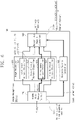
- FIG. 1 is a block diagram illustrating an image recognition device 100 according to an embodiment of the inventive concept.
- the image recognition device 100 includes a frame data change detector 110 , an ensemble section controller 120 , an image recognizer 130 , and a recognition result classifier 140 .
- the frame data change detector 110 may sequentially receive a plurality of frame data from an external device.
- the frame data change detector 110 is illustrated to receive nth to n+3th frame data F(n) to F(n+3) (where n is a positive integer), but the inventive concept is not limited thereto.
- the frame data change detector 110 may detect a change in the plurality of frame data from the received the nth to n+3th frame data F(n) to F(n+3). For example, the frame data change detector 110 may detect the change of data in two consecutive frame data.
- the frame data change detector 110 may transmit an nth change V(n) indicating that entire frame data is changed to the ensemble section controller 120 .
- the frame data change detector 110 may detect a change V(n+1) (e.g., a difference) between the nth frame data F(n), which is previous frame data, and the n+1th frame data F(n+1), which is currently received frame data.
- the frame data change detector 110 may transmit the detected n+1th change V(n+1) to the ensemble section controller 120 .
- the frame data change detector 110 may transmit an n+2th change V(n+2) between the n+1th frame data F(n+1) and the n+2th frame data F(n+2) to the ensemble section controller 120 .
- the frame data change detector 110 may transmit an n+3th change V(n+3) between the n+2th frame data F(n+2) and the n+3th frame data F(n+3) to the ensemble section controller 120 .
- the frame data change detector 110 may transmit the nth frame data F(n) to the n+3th frame data F(n+3) to the image recognizer 130 .
- the frame data change detector 110 may alternately transmit the nth to n+3th frame data F(n) to F(n+3) to different neural network classifiers (e.g., first to fourth neural network classifiers 131 to 134 ) of the image recognizer 130 .
- the ensemble section controller 120 may receive the nth to n+3 changes V(n) to V(n+3) from the frame data change detector 110 .
- the ensemble section controller 120 may set an ensemble section, based on the received nth to n+3 changes V(n) to V(n+3). For example, the ensemble section controller 120 may determine a start of the ensemble section and an end of the ensemble section, and may transmit the determined result to the recognition result classifier 140 .
- the ensemble section controller 120 may determine frame data corresponding to the change as the start of a new ensemble section. Also, the ensemble section controller 120 may determine previous frame data as the end of previous ensemble section.
- the image recognizer 130 may include two or more neural network classifiers.
- the image recognizer 130 is illustrated as including the first to fourth neural network classifiers 131 to 134 , but the number of neural network classifiers included in the image recognizer 130 is not limited thereto.
- the first to fourth neural network classifiers 131 to 134 of the image recognizer 130 may include neural network classification algorithms that are learned in different ways.
- the first to fourth neural network classifiers 131 to 134 may be learned differently by different machine learning algorithms such as a convolutional neural network (CNN), a recurrent neural network (RNN), etc.
- CNN convolutional neural network
- RNN recurrent neural network
- the first to fourth neural network classifiers 131 to 134 may be learned differently by using the same machine learning algorithm, but by varying the number of nodes in an input layer, that is, by varying the number of input parameters. As another example, the first to fourth neural network classifiers 131 to 134 may be learned differently by varying the number of nodes in a hidden layer. As another example, the first to fourth neural network classifiers 131 to 134 may be learned differently by using different learning data for machine learning.
- the first to fourth neural network classifiers 131 to 134 may share the same operation resource.
- the first to fourth neural network classifiers 131 to 134 may be alternately activated to share the operation resource to perform a neural network classification.
- the first to fourth neural network classifiers 131 to 134 may receive the plurality of frame data at different time from the frame data change detector 110 .
- the first neural network classifier 131 may receive the nth frame data F(n) at a nth time, and may identify nth classes C(n) in the nth frame data F(n).
- the second neural network classifier 132 may receive the n+1th frame data F(n+1) at a n+1th time, and may identify n+1th classes C(n+1) in the n+1th frame data F(n+1).
- the third neural network classifier 133 may receive the n+2th frame data F(n+2) at a n+2th time, and may identify n+2th classes C(n+2) in the n+2th frame data F(n+2).
- the fourth neural network classifier 134 may receive the n+3th frame data F(n+3) at a n+3th time, and may identify n+3th classes C(n+3) in the n+3th frame data F(n+3).
- the first to fourth neural network classifiers 131 to 134 may be sequentially activated again.
- the first to fourth neural network classifiers 131 to 134 may receive the plurality of frame data at a n+4th time to a n+7th time, respectively, and may respectively identify the classes from the plurality of frame data that are received.
- the recognition result classifier 140 may sequentially receive the nth classes C(n) to the n+3th classes C(n+3) from the first to fourth neural network classifiers 131 to 134 of the image recognizer 130 .
- the recognition result classifier 140 may recognize the ensemble section under control of the ensemble section controller 120 .
- the recognition result classifier 140 may generate nth to n+3th ensemble classes EC(n) to EC(n+3) by combining the classes belonging to the same ensemble section. For example, at a specific time, for example at the n+1th time, the recognition result classifier 140 may generate the n+1th ensemble class EC(n+1) by combining classes identified in the plurality of frame data that precedes the n+1th frame data F(n+1) and belongs to the same ensemble section as the n+1th frame data F(n+1) and the n+1th class C(n+1) identified in the n+1th frame data F(n+1).
- the plurality of frame data may be considered to be the same one frame.
- an effect of applying the different neural network algorithms to the same frame may occur. Since the different neural network classifiers share the same operation resource, the accuracy of image recognition may be improved while reducing or maintaining the operation resource.
- the frame data change detector 110 is illustrated as transmitting the plurality of frame data to the first to fourth neural network classifiers 131 to 134 through different paths. However, the frame data change detector 110 may transmit the plurality of frame data to the image recognizer 130 through the same path.
- the image recognizer 130 may multiplex the plurality of frame data transmitted from the frame data change detector 110 and may sequentially distribute the multiplexed plurality of frame data to the first to fourth neural network classifiers 131 to 134 .
- the first to fourth neural network classifiers 131 to 134 are illustrated as transmitting the classes through different paths to the recognition result classifier 140 .
- the image recognizer 130 may demultiplex the classes output from the first to fourth neural network classifiers 131 to 134 and may sequentially transmit the demultiplexed classes to the recognition result classifier 140 through the same path.
- FIG. 2 is a flowchart describing an operating method of the image recognition device 100 according to an embodiment of the inventive concept.
- the ensemble section controller 120 of the image recognition device 100 may set the ensemble section, based on the change of the plurality of frame data.
- the image recognizer 130 of the image recognition device 100 may sequentially identify the classes by applying the different neural network classifiers to the plurality of frame data that are sequentially received in the ensemble section.
- the recognition result classifier 140 of the image recognition device 100 may sequentially identify the ensemble classes by combining the classes that are sequentially identified in the ensemble section.
- FIG. 3 is a flowchart describing how the image recognition device 100 recognizes an image from a plurality of frame data.
- the frame data change detector 110 of the image recognition device 100 may receive the frame data.
- the frame data change detector 110 may detect the difference (e.g., change) between the received frame data and the previous frame data. The detected difference is transmitted to the ensemble section controller 120 .
- the ensemble section controller 120 of the image recognition device 100 may determine whether the detected difference is greater than or equal to the first threshold. When the detected difference is less than the first threshold, in operation S 240 , the ensemble section controller 120 may identify the received frame data and the previous frame data as the same ensemble section. For example, the ensemble section controller 120 may incorporate the received frame data into the ensemble section of the previous frame data. Thereafter, operation S 260 is performed.
- the ensemble section controller 120 may identify the received frame data and the previous frame data as different ensemble sections. For example, the ensemble section controller 120 may set the previous frame data as the end of the ensemble section. The ensemble section controller 120 may set the received frame data as the start of a new ensemble section. Thereafter, operation S 260 is performed.
- the image recognizer 130 may recognize the classes from the received frame data by using the subsequent neural network classifier of a neural network classifier that processes the previous frame data.
- the recognition result classifier 140 may recognize the ensemble classes by combining the recognized classes with previously recognized classes in the ensemble section.
- the ensemble section controller 120 may limit the number of the plurality of frame data included in one ensemble section. For example, when the number of the plurality of frame data incorporated in one ensemble section reaches a specific value (e.g., threshold value), the ensemble section controller 120 may set the received frame data as the end of the ensemble section, regardless of the difference in the plurality of frame data.
- a specific value e.g., threshold value
- the ensemble section controller 120 may set the start of a new ensemble section. Accordingly, since storage space for storing classes of the plurality of frame data is limited, the resource required for the image recognition may be decreased.
- FIG. 4 is a diagram illustrating how the image recognition device 100 recognizes an image from nth frame data F(n). For example, it is assumed that the nth frame data F(n) is the first frame data received in the image recognition device 100 . Referring to FIG. 4 , in operation S 311 , the frame data change detector 110 may receive the nth frame data F(n).
- the frame data change detector 110 may detect the nth change V(n) between the nth frame data F(n) and the previous frame data.
- the nth change V(n) indicates that the entire nth frame data F(n) is changed, and may be equal to or greater than the first threshold.
- the ensemble section controller 120 may set the nth frame data F(n) as the start of a new ensemble section.
- the nth frame data F(n) may be transferred to the first neural network classifier 131 .
- the first neural network classifier 131 may identify the first class C 1 ( n ) and the second class C 2 ( n ) from the nth frame data F(n).
- the first class C 1 ( n ) and the second class C 2 ( n ) are transferred to the recognition result classifier 140 .
- the recognition result classifier 140 may output the first class C 1 ( n ) as a first ensemble class EC 1 ( n ), and may output the second class C 2 ( n ) as a second ensemble class EC 2 ( n ).
- FIG. 5 is a diagram illustrating how the image recognition device 100 recognizes an image from the n+1th frame data F(n+1).
- the frame data change detector 110 may receive the n+1th frame data F(n+1).
- the frame data change detector 110 may detect the n+1th change V(n+1) between the n+1th frame data F(n+1) and the nth frame data F(n) that is previous frame data. For example, it is assumed that the n+1th change V(n+1) is less than the first threshold.
- the ensemble section controller 120 may incorporate the n+1th frame data F(n+1) into the ensemble section of the nth frame data F(n).
- the n+1th frame data F(n+1) may be transferred to the second neural network classifier 132 .
- the second neural network classifier 132 may identify the first class C 1 ( n +1) and the second class C 2 ( n +1) from the n+1th frame data F(n+1).
- the first class C 1 ( n +1) and the second class C 2 ( n +1) are transferred to the recognition result classifier 140 .
- the recognition result classifier 140 may output an average of the first classes C 1 ( n ) and C 1 ( n +1), for example, an average of probabilities as a first ensemble class EC 1 ( n +1). Also, the recognition result classifier 140 may output an average of the second classes C 2 ( n ) and C 2 ( n +1), for example, the average of the probabilities as a second ensemble class EC 2 ( n +1).
- FIG. 6 is a diagram illustrating how the image recognition device 100 recognizes an image from the n+2th frame data F(n+2).
- the frame data change detector 110 may receive the n+2th frame data F(n+2).
- the frame data change detector 110 may detect the n+2th change V(n+2) between the n+2th frame data F(n+2) and the n+1th frame data F(n+1) that is previous frame data. For example, it is assumed that the n+2th change V(n+2) is less than the first threshold.
- the ensemble section controller 120 may incorporate the n+2th frame data F(n+2) into the ensemble section of the n+1th frame data F(n+1).
- the n+2th frame data F(n+2) may be transferred to the third neural network classifier 133 .
- the third neural network classifier 133 may identify a first class C 1 ( n +2) and a third class C 3 ( n +2) from the n+2th frame data F(n+2).
- the first class C 1 ( n +2) and the third class C 3 ( n +2) are transferred to the recognition result classifier 140 .
- the recognition result classifier 140 may output an average of the first classes C 1 ( n ), C 1 ( n +1), and C 1 ( n +2), for example, the average of the probabilities as a first ensemble class EC 1 ( n +2). Also, the recognition result classifier 140 may output the third class C 3 ( n +2) as a third ensemble class EC 3 (n+2).
- FIG. 7 is a diagram illustrating how an image recognition device 100 recognizes an image from the n+3th frame data F(n+3).
- the frame data change detector 110 may receive the n+3th frame data F(n+3).
- the frame data change detector 110 may detect the n+3th change V(n+3) between the n+3th frame data F(n+3) and the n+2th frame data F(n+2) that is previous frame data. For example, it is assumed that the n+3th change V(n+3) is equal to or greater than the first threshold.
- the ensemble section controller 120 may set the n+3th frame data F(n+3) as the start of a new ensemble section, and may set the n+2th frame data F(n+2) as the end of the ensemble section.
- the n+3th frame data F(n+3) may be transferred to the fourth neural network classifier 134 .
- the fourth neural network classifier 134 may identify a fourth class C 4 ( n +3) and a fifth class C 5 ( n +3) from the n+3th frame data F(n+3).
- the fourth class C 4 ( n +3) and the fifth class C 5 ( n +3) are transferred to the recognition result classifier 140 .
- the recognition result classifier 140 may output the fourth class C 4 ( n +3) as a fourth ensemble class EC 4 ( n +3).
- the recognition result classifier 140 may output the fifth class C 5 ( n +3) as a fifth ensemble class EC 5 ( n +3).
- the n+4th frame data may be processed again by the first neural network classifier 131 .
- the second to fourth neural network classifiers 132 to 134 may be sequentially activated for n+5th to n+7th frame data.
- FIG. 8 is a diagram illustrating an image recognition device 200 according to another embodiment of the inventive concept.
- the image recognition device 200 includes a frame data change detector 210 , an ensemble section controller 220 , an image recognizer 230 , and a recognition result classifier 240 .
- the image recognizer 230 may include first to fourth neural network classifiers 231 to 234 .
- the frame data change detector 210 , the ensemble section controller 220 , the image recognizer 230 , and the recognition result classifier 240 may operate in the same manner as the frame data change detector 110 , the ensemble section controller 120 , the image recognizer 130 , and the recognition result classifier 140 , which are described with reference to FIG. 1 .
- the recognition result classifier 240 may detect a difference VC(n), VC(n+1), VC(n+2), or VC(n+3) between classes C(n), C(n+1), C(n+2), or C(n+3) identified from currently received frame data F(n), F(n+1), F(n+2), or F(n+3) and classes identified from previous frame data
- the recognition result classifier 240 may transfer the detected difference VC(n), VC(n+1), VC(n+2), or VC(n+3) to the ensemble section controller 220 .
- the ensemble section controller 220 may correct an ensemble section that is set based on a change V(n), V(n+1), V(n+2) or V(n+3) by using the difference VC(n), VC(n+1), VC(n+2), or VC(n+3).
- FIG. 9 is a flowchart describing an operating method of the image recognition device 200 of FIG. 8 .
- operations S 410 to S 460 are performed in the same manner as operations S 210 to S 260 in FIG. 3 . Therefore, additional descriptions thereof will be omitted to avoid redundancy.
- the recognition result classifier 240 may detect a difference VC(n), VC(n+1), VC(n+2), or VC(n+3) (or change) between classes C(n), C(n+1), C(n+2), or C(n+3) identified from the currently received frame data F(n), F(n+1), F(n+2), or F(n+3) and classes identified from previous frame data.
- the difference VC(n), VC(n+1), VC(n+2), or VC(n+3) may include a difference in type or number of the identified classes C(n), C(n+1), C(n+2), or C(n+3), or a difference in probability of each of the identified classes C(n), C(n+1), C(n+2), or C(n+3).
- the ensemble section controller 220 may determine whether the detected difference VC(n), VC(n+1), VC(n+2), or VC(n+3) is greater than or equal to a second threshold. When the detected difference VC(n), VC(n+1), VC(n+2), or VC(n+3) is less than the second threshold, in operation S 481 , the ensemble section controller 220 may maintain an existing ensemble section set based on the change V(n), V(n+1), V(n+2) or V(n+3). Thereafter, operation S 490 may be performed. Operation S 490 may be performed in the same manner as operation S 270 .
- the ensemble section controller 220 may identify the currently received frame data F(n), F(n+1), F(n+2), or F(n+3) and the previous frame data as different ensemble sections.
- the two frame data may be incorporated into different ensemble sections.
- preceding frame data may be set to the end of the existing ensemble section, and the subsequent frame data may be set to the start of the new ensemble section.
- operation S 490 is performed. Operation S 490 may be performed in the same manner as operation S 270 .
- FIG. 10 is a block diagram illustrating a computing device 300 according to an embodiment of the inventive concept.
- the computing device 300 includes a processor 310 , a main memory 320 , an image recognition device 330 , a device manager 340 , a storage device 350 , a camera 360 , and a modem 370 .
- the processor 310 may execute an operating system operating the computing device 300 and various commands and codes.
- the processor 310 may include an application processor (AP) or a central processing unit (CPU).
- AP application processor
- CPU central processing unit
- the main memory 320 may be an operating memory of the processor 310 .
- the main memory 320 may include a dynamic random access memory (DRAM) or a storage class memory (SCM).
- DRAM dynamic random access memory
- SCM storage class memory
- the image recognition device 330 may include the image recognition device 100 or 200 according to an embodiment of the inventive concept.
- the image recognition device 330 may be an auxiliary processor configured to perform the operations, methods, or processes described with reference to FIGS. 1 to 9 .
- the image recognition device 330 may be a graphic processing unit (GPU) or a neural network processing unit (NPU).
- the device manager 340 may connect the processor 310 and peripheral devices of the computing device 300 to one another.
- the device manager 340 may connect the storage device 350 , the camera 360 , and the modem 370 to the processor 310 .
- the storage device 350 may be an auxiliary storage device of the computing device 300 .
- the storage device 350 may include a hard disk drive (HDD), a solid state drive (SSD), an optical disk drive (ODD), or a removable memory card such as a USB memory.
- HDD hard disk drive
- SSD solid state drive
- ODD optical disk drive
- USB memory a removable memory card
- the camera 360 may be configured to capture external scenes and to generate a plurality of frame data.
- the modem 370 may be configured to communicate with the external device.
- the modem 370 may communicate the plurality of frame data with the external device.
- the plurality of frame data that are obtained by the camera 360 or the modem 370 may be stored in the main memory 320 .
- the processor 310 may request the image recognition device 330 to perform image recognition with respect to the plurality of frame data stored in the main memory 320 .
- the processor 310 may receive a result of image recognition from the image recognition device 330 , for example, ensemble classes.
- the processor 310 may perform subsequent processing using the ensemble classes.
- the plurality of frame data loaded in the main memory 320 may be stored in the storage device 350 .
- components of the image recognition device 100 or 200 are described using terms such as first, second, third, etc.
- terms such as first, second, and third are used to distinguish components from one another, and do not limit the inventive concept.
- terms such as first, second, third, etc. do not imply numerical meaning in any order or in any form.
- the blocks may be implemented as various hardware devices such as an Integrated Circuit (IC), an Application Specific IC (ASIC), a Field Programmable Gate Array (FPGA), and a Complex Programmable Logic Device (CPLD), a firmware running on hardware devices, software such as an application, or a combination of hardware devices and software.
- the blocks may include circuits composed of semiconductor elements in the IC or circuits registered as IP (Intellectual Property).
- an image recognition device identifies classes by applying different neural network classifiers to a plurality of frame data sequentially received, and combines the identified classes to combine classification results of the different neural network classifiers.
- the different neural network classifiers are activated alternately, and perform an operation using a common resource. Accordingly, the image recognition device capable of increasing an accuracy of image recognition, while reducing or maintaining a resource required for the image recognition, a method of operating the image recognition device, and a computing device including the image recognition device are provided.
- inventive concept may include not only the embodiments described above but also embodiments in which a design is simply or easily capable of being changed.
- inventive concept may also include technologies easily changed to be implemented using embodiments. Therefore, the scope of the inventive concept is not limited to the described embodiments but should be defined by the claims and their equivalents.
Abstract
Description
Claims (20)
Applications Claiming Priority (2)
| Application Number | Priority Date | Filing Date | Title |
|---|---|---|---|
| KR1020190054994A KR20200130602A (en) | 2019-05-10 | 2019-05-10 | Image recognition device, operating method of image recognition device, and computing device including image recognition device |
| KR10-2019-0054994 | 2019-05-10 |
Publications (2)
| Publication Number | Publication Date |
|---|---|
| US20200356804A1 US20200356804A1 (en) | 2020-11-12 |
| US11449720B2 true US11449720B2 (en) | 2022-09-20 |
Family
ID=73046730
Family Applications (1)
| Application Number | Title | Priority Date | Filing Date |
|---|---|---|---|
| US16/870,412 Active 2040-12-05 US11449720B2 (en) | 2019-05-10 | 2020-05-08 | Image recognition device, operating method of image recognition device, and computing device including image recognition device |
Country Status (2)
| Country | Link |
|---|---|
| US (1) | US11449720B2 (en) |
| KR (1) | KR20200130602A (en) |
Families Citing this family (1)
| Publication number | Priority date | Publication date | Assignee | Title |
|---|---|---|---|---|
| KR102293547B1 (en) * | 2021-03-08 | 2021-08-26 | 주식회사 에스아이에이 | Method and apparatus for detecting change |
Citations (16)
| Publication number | Priority date | Publication date | Assignee | Title |
|---|---|---|---|---|
| US5799276A (en) * | 1995-11-07 | 1998-08-25 | Accent Incorporated | Knowledge-based speech recognition system and methods having frame length computed based upon estimated pitch period of vocalic intervals |
| US20070110158A1 (en) * | 2004-03-11 | 2007-05-17 | Canon Kabushiki Kaisha | Encoding apparatus, encoding method, decoding apparatus, and decoding method |
| US20100287125A1 (en) * | 2008-05-21 | 2010-11-11 | Sony Corporation | Information processing unit, information processing method, and program |
| US20120069183A1 (en) * | 2010-09-16 | 2012-03-22 | Kabushiki Kaisha Toshiba | Vehicle detection apparatus |
| US20120124037A1 (en) | 2010-11-17 | 2012-05-17 | Electronics And Telecommunications Research Institute | Multimedia data searching method and apparatus and pattern recognition method |
| US20140181668A1 (en) * | 2012-12-20 | 2014-06-26 | International Business Machines Corporation | Visual summarization of video for quick understanding |
| US20140269461A1 (en) * | 2013-03-14 | 2014-09-18 | Qualcomm Incorporated | Systems and methods for link augmentation |
| US9524450B2 (en) | 2015-03-04 | 2016-12-20 | Accenture Global Services Limited | Digital image processing using convolutional neural networks |
| US20180121601A1 (en) * | 2016-10-28 | 2018-05-03 | Edico Genome, Corp. | Bioinformatics systems, apparatuses, and methods for performing secondary and/or tertiary processing |
| US20180174044A1 (en) | 2016-12-16 | 2018-06-21 | Samsung Electronics Co., Ltd. | Recognition method and apparatus |
| US20180189596A1 (en) | 2017-01-03 | 2018-07-05 | Electronics And Telecommunications Research Institute | Machine learning method and apparatus |
| US20180205919A1 (en) * | 2015-07-27 | 2018-07-19 | Nec Display Solutions, Ltd. | Projector device and method for correcting color in projector device |
| US10157309B2 (en) | 2016-01-14 | 2018-12-18 | Nvidia Corporation | Online detection and classification of dynamic gestures with recurrent convolutional neural networks |
| US20180365532A1 (en) * | 2017-06-20 | 2018-12-20 | Nvidia Corporation | Semi-supervised learning for landmark localization |
| US20190354388A1 (en) * | 2018-05-18 | 2019-11-21 | Adobe Inc. | Tenant-side detection, classification, and mitigation of noisy-neighbor-induced performance degradation |
| US20220030230A1 (en) * | 2019-03-15 | 2022-01-27 | Mux, Inc. | Method for generating video- and audience-specific encoding ladders |
-
2019
- 2019-05-10 KR KR1020190054994A patent/KR20200130602A/en active Search and Examination
-
2020
- 2020-05-08 US US16/870,412 patent/US11449720B2/en active Active
Patent Citations (17)
| Publication number | Priority date | Publication date | Assignee | Title |
|---|---|---|---|---|
| US5799276A (en) * | 1995-11-07 | 1998-08-25 | Accent Incorporated | Knowledge-based speech recognition system and methods having frame length computed based upon estimated pitch period of vocalic intervals |
| US20070110158A1 (en) * | 2004-03-11 | 2007-05-17 | Canon Kabushiki Kaisha | Encoding apparatus, encoding method, decoding apparatus, and decoding method |
| US20100287125A1 (en) * | 2008-05-21 | 2010-11-11 | Sony Corporation | Information processing unit, information processing method, and program |
| US20120069183A1 (en) * | 2010-09-16 | 2012-03-22 | Kabushiki Kaisha Toshiba | Vehicle detection apparatus |
| US20120124037A1 (en) | 2010-11-17 | 2012-05-17 | Electronics And Telecommunications Research Institute | Multimedia data searching method and apparatus and pattern recognition method |
| US20140181668A1 (en) * | 2012-12-20 | 2014-06-26 | International Business Machines Corporation | Visual summarization of video for quick understanding |
| US20140269461A1 (en) * | 2013-03-14 | 2014-09-18 | Qualcomm Incorporated | Systems and methods for link augmentation |
| US9524450B2 (en) | 2015-03-04 | 2016-12-20 | Accenture Global Services Limited | Digital image processing using convolutional neural networks |
| US20180205919A1 (en) * | 2015-07-27 | 2018-07-19 | Nec Display Solutions, Ltd. | Projector device and method for correcting color in projector device |
| US10157309B2 (en) | 2016-01-14 | 2018-12-18 | Nvidia Corporation | Online detection and classification of dynamic gestures with recurrent convolutional neural networks |
| US20180121601A1 (en) * | 2016-10-28 | 2018-05-03 | Edico Genome, Corp. | Bioinformatics systems, apparatuses, and methods for performing secondary and/or tertiary processing |
| US20180174044A1 (en) | 2016-12-16 | 2018-06-21 | Samsung Electronics Co., Ltd. | Recognition method and apparatus |
| KR20180070103A (en) | 2016-12-16 | 2018-06-26 | 삼성전자주식회사 | Method and apparatus for recognition |
| US20180189596A1 (en) | 2017-01-03 | 2018-07-05 | Electronics And Telecommunications Research Institute | Machine learning method and apparatus |
| US20180365532A1 (en) * | 2017-06-20 | 2018-12-20 | Nvidia Corporation | Semi-supervised learning for landmark localization |
| US20190354388A1 (en) * | 2018-05-18 | 2019-11-21 | Adobe Inc. | Tenant-side detection, classification, and mitigation of noisy-neighbor-induced performance degradation |
| US20220030230A1 (en) * | 2019-03-15 | 2022-01-27 | Mux, Inc. | Method for generating video- and audience-specific encoding ladders |
Also Published As
| Publication number | Publication date |
|---|---|
| KR20200130602A (en) | 2020-11-19 |
| US20200356804A1 (en) | 2020-11-12 |
Similar Documents
| Publication | Publication Date | Title |
|---|---|---|
| KR102348593B1 (en) | Method for detecting target object based on machine-learning and Apparatus thereof | |
| CN106415594B (en) | Method and system for face verification | |
| US20200117886A1 (en) | Fast, embedded, hybrid video face recognition system | |
| US11121949B2 (en) | Distributed assignment of video analytics tasks in cloud computing environments to reduce bandwidth utilization | |
| US10102421B2 (en) | Method and device for face recognition in video | |
| US10346726B2 (en) | Image recognition method and apparatus, image verification method and apparatus, learning method and apparatus to recognize image, and learning method and apparatus to verify image | |
| US20190279052A1 (en) | Image recognition method and apparatus, image verification method and apparatus, learning method and apparatus to recognize image, and learning method and apparatus to verify image | |
| US20190236437A1 (en) | Heterogeneous processor architecture for integrating cnn and rnn into single high-performance, low-power chip | |
| Ravi et al. | Explicitly imposing constraints in deep networks via conditional gradients gives improved generalization and faster convergence | |
| US11715281B2 (en) | System and method for detecting objects in a digital image, and system and method for rescoring object detections | |
| US11144748B2 (en) | Classification system | |
| US10152637B2 (en) | Temporal segmentation of actions using context features | |
| US20210216831A1 (en) | Efficient Machine Learning (ML) Model for Classification | |
| US11302108B2 (en) | Rotation and scaling for optical character recognition using end-to-end deep learning | |
| US11449720B2 (en) | Image recognition device, operating method of image recognition device, and computing device including image recognition device | |
| US20190279100A1 (en) | Low latency interrupt alerts for artificial neural network systems and methods | |
| WO2019171779A1 (en) | Object detection device, object detection method, and program | |
| US20220019897A1 (en) | Deep neural network training accelerator and operation method thereof | |
| US20190303714A1 (en) | Learning apparatus and method therefor | |
| US11195083B2 (en) | Object detection system and object detection method | |
| Xia et al. | Tree-structured support vector machines for multi-class classification | |
| CN113792804A (en) | Training method of image recognition model, image recognition method, device and equipment | |
| KR20180082680A (en) | Method for learning classifier and prediction classification apparatus using the same | |
| KR20210123674A (en) | Method for detecting out-of-distribution data using test-time augmentation and apparatus performing the same | |
| US11966846B2 (en) | Method of performing learning of deep neural network and apparatus thereof |
Legal Events
| Date | Code | Title | Description |
|---|---|---|---|
| FEPP | Fee payment procedure |
Free format text: ENTITY STATUS SET TO UNDISCOUNTED (ORIGINAL EVENT CODE: BIG.); ENTITY STATUS OF PATENT OWNER: SMALL ENTITY |
|
| AS | Assignment |
Owner name: ELECTRONICS AND TELECOMMUNICATIONS RESEARCH INSTITUTE, KOREA, REPUBLIC OF Free format text: ASSIGNMENT OF ASSIGNORS INTEREST;ASSIGNORS:KIM, JU-YEOB;KIM, BYUNG JO;KIM, SEONG MIN;AND OTHERS;REEL/FRAME:052623/0474 Effective date: 20200422 |
|
| FEPP | Fee payment procedure |
Free format text: ENTITY STATUS SET TO SMALL (ORIGINAL EVENT CODE: SMAL); ENTITY STATUS OF PATENT OWNER: SMALL ENTITY |
|
| STPP | Information on status: patent application and granting procedure in general |
Free format text: APPLICATION DISPATCHED FROM PREEXAM, NOT YET DOCKETED |
|
| STPP | Information on status: patent application and granting procedure in general |
Free format text: DOCKETED NEW CASE - READY FOR EXAMINATION |
|
| STPP | Information on status: patent application and granting procedure in general |
Free format text: NON FINAL ACTION MAILED |
|
| STPP | Information on status: patent application and granting procedure in general |
Free format text: RESPONSE TO NON-FINAL OFFICE ACTION ENTERED AND FORWARDED TO EXAMINER |
|
| STPP | Information on status: patent application and granting procedure in general |
Free format text: NOTICE OF ALLOWANCE MAILED -- APPLICATION RECEIVED IN OFFICE OF PUBLICATIONS |
|
| STCF | Information on status: patent grant |
Free format text: PATENTED CASE |