US11448480B2 - Adjustable position magazine carrier - Google Patents
Adjustable position magazine carrier Download PDFInfo
- Publication number
- US11448480B2 US11448480B2 US17/569,683 US202217569683A US11448480B2 US 11448480 B2 US11448480 B2 US 11448480B2 US 202217569683 A US202217569683 A US 202217569683A US 11448480 B2 US11448480 B2 US 11448480B2
- Authority
- US
- United States
- Prior art keywords
- aperture
- accessory
- assembly
- holster
- planar surface
- Prior art date
- Legal status (The legal status is an assumption and is not a legal conclusion. Google has not performed a legal analysis and makes no representation as to the accuracy of the status listed.)
- Active
Links
Images


Classifications
-
- F—MECHANICAL ENGINEERING; LIGHTING; HEATING; WEAPONS; BLASTING
- F41—WEAPONS
- F41C—SMALLARMS, e.g. PISTOLS, RIFLES; ACCESSORIES THEREFOR
- F41C33/00—Means for wearing or carrying smallarms
- F41C33/02—Holsters, i.e. cases for pistols having means for being carried or worn, e.g. at the belt or under the arm
- F41C33/04—Special attachments therefor
- F41C33/041—Special attachments therefor for connecting a holster to a belt, webbing or other object
- F41C33/045—Special attachments therefor for connecting a holster to a belt, webbing or other object for connection in more than one rotational position around an axle, e.g. by using a rotatable connection
-
- F—MECHANICAL ENGINEERING; LIGHTING; HEATING; WEAPONS; BLASTING
- F41—WEAPONS
- F41C—SMALLARMS, e.g. PISTOLS, RIFLES; ACCESSORIES THEREFOR
- F41C33/00—Means for wearing or carrying smallarms
- F41C33/02—Holsters, i.e. cases for pistols having means for being carried or worn, e.g. at the belt or under the arm
- F41C33/04—Special attachments therefor
-
- F—MECHANICAL ENGINEERING; LIGHTING; HEATING; WEAPONS; BLASTING
- F42—AMMUNITION; BLASTING
- F42B—EXPLOSIVE CHARGES, e.g. FOR BLASTING, FIREWORKS, AMMUNITION
- F42B39/00—Packaging or storage of ammunition or explosive charges; Safety features thereof; Cartridge belts or bags
- F42B39/02—Cartridge bags; Bandoleers
Definitions
- the present invention relates to the field of devices designed for the holding of tactical gear. More specifically, the present invention relates to devices designed to attach accessories to the gun holster of a user.
- Holsters are devices that are used to hold, carry and/or restrict the movement of a weapon, such as a handgun, and they are most commonly in a location where the weapon can be withdrawn for immediate use.
- Holsters typically have mounting points that enable accessories to be attached directly to the holster for items such as clips for the belt, belt loops, paddles, and modular, lightweight, load-carrying equipment (MOLLE) adaptors for attaching various types of gear.
- MOLLE modular, lightweight, load-carrying equipment
- These mounting positions typically do not have a solid surface and therefore lack stability for the attachment of many accessories.
- positioning of these accessories is typically limited to the holster mounting point locations, which are usually around the edges of the holster and only allows one set mounting position.
- the best location and position of the accessories, such as a magazine carrier, as related to the user is variable depending on several factors. Among these are the body type of the user, training background of the user, intended mission, operational environment, and a consideration of other gear that may or may not be necessary for the user to carry on person at the same time as the holster. Taken together the greater the range of adjustment and options in mounting and positioning of the accessory the more likely the user is able to incorporate the weapon and accessory in an orientation that is most effective for the intended purpose.
- the present invention substantially expands the user's options, in a way not possible without use of the present invention, for mounting, attaching and carrying an accessory such as a magazine carrier with the holstered weapon.
- the present invention provides a solid mounting plate for attaching a magazine carrier, or other comparable accessory, to a holster.
- the present invention further allows for variation in magazine carrier positioning with respect to the holster. Elevation of the mounting surface can also be an advantage as it reduces substantially the stresses that are placed on, and to, the surface geometry or shape of the holster when the magazine carrier is attached directly to the surface of the holster. Such stress negatively affects the fit and retention qualities of a holster by deforming or warping the intended surface shape of the holster exteriors.
- the present invention reduces this effect or eliminates it completely as it elevates the mounted magazine carrier above the form-fitting surface of the holster.
- the present invention allows direct attachment of the magazine carrier, or other accessories, to the holster in a location where the holster is structurally suited for the stress associated with mounting while enabling positioning of the accessory to be in the most ideal location and orientation for the task.
- the present invention allows for pivoting of the accessory holder away from the vertical plane of the holster up to about 35 degrees.
- FIG. 1 is a top view of the mounting plate of the present invention.
- FIG. 2 is a side view of the mounting plate of the present invention.
- FIG. 3A is a side view of the present invention showing a variety of adjustable mounting positions for the magazine carrier with the magazine carrier and mounting plate parallel to the holster prominent.
- FIG. 3B is a side view of the present invention showing a variety of adjustable mounting positions for the magazine carrier with the magazine carrier and mounting plate angled away from the vertical plane of the holster prominent.
- FIG. 4 is a side view of the present invention in one of the variety of adjustable mounting positions on the holster.
- FIG. 5 is a side view of the present invention in one of the variety of adjustable mounting positions on the holster.
- FIG. 6 is an opposing side view of the present invention in the adjustable mounting position shown in FIG. 5 .
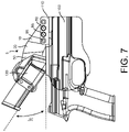
- FIG. 7 is a side view of the present invention in one of the variety of adjustable mounting positions on the holster.
- the mounting plate 5 comprises a first planar surface 10 , a middle planar surface 20 having a proximal end 30 and a distal end 40 , and a second planar surface 50 wherein the first planar surface 10 attaches to the proximal end 30 of the middle planar surface 20 and the second planar surface 50 attaches to the distal end 40 of the middle planar surface 20 .
- This patent anticipates various configurations of the planar surfaces in relation to each other.
- all three planar surfaces 10 , 20 , 50 may aligned in the same continuous plane, or alternatively, the first planar surface 10 may be slightly offset from the second planar surface 50 by a vertical bend equal to angle ⁇ (as shown in FIG. 1 ) up to 13° in relation to the horizontal plane of the first planar surface 10 .
- the first planar surface 10 and second planar surface 50 further comprise a plurality of mounting apertures used to attach the mounting plate 5 to other accessories, such as a holster 100 and a magazine carrier 130 as depicted in FIGS. 3-7 .
- the first planar surface 10 has at least one anchor aperture 80 and at least one adjustable aperture 85 positioned in series in a horizontal direction towards the proximal end 30 of the middle planar surface 20 .
- the vertical height 75 of each adjustable aperture 85 in series increases towards the proximal end 30 of the middle planar surface 20 such that one side 60 of each adjustable aperture 85 is substantially axially aligned with the anchor aperture 80 and the opposing side 60 of each adjustable aperture 85 is offset from the anchor aperture 80 by a first accessory angle ⁇ .
- the second planar surface 50 has at least one anchor aperture 80 and at least one adjustable aperture 85 positioned in series in a vertical direction along the second planar surface 50 .
- the width 70 of each adjustable aperture 85 in series increases such that one side 60 of the adjustable aperture 85 is substantially axially aligned with the anchor aperture 80 and the opposing side 60 of the adjustable aperture 85 is offset by a second accessory angle ⁇ .
- fasteners e.g. screws
- Adjustable aperture(s) 85 allow the mounting plate 5 to be secured at various position with respect to the vertical plane of the holster 100 ; specifically, mounting plate 5 and magazine carrier 130 may pivot around the anchor aperture 80 up to the first accessory angle ⁇ away from the vertical plane of the holster 100 .
- first accessory angle ⁇ ranges from 0° to 12°.
- Similar fasteners or screws may be used to attach the bracket 5 to an accessory, such as a magazine carrier 130 , by threading the screw through the anchor aperture 80 and the adjustable aperture(s) 85 on the second planar surface 50 (as shown in FIG. 6 ).
- Adjustable aperture(s) 85 allow for the magazine carrier 130 to be secured at various positions with respect to the mounting plate 5 ; specifically, the magazine carrier 130 may pivot around the anchor aperture 80 in a circumferential direction up to the second accessory angle ⁇ away from the vertical plane of the second planar surface 50 .
- the second accessory angle ⁇ ranges from 0° to 25°.
- the magazine carrier 130 may be rotatably adjusted up to 35° from the vertical plane of the holster 100 .
Abstract
Description
Claims (12)
Priority Applications (1)
| Application Number | Priority Date | Filing Date | Title |
|---|---|---|---|
| US17/569,683 US11448480B2 (en) | 2018-07-13 | 2022-01-06 | Adjustable position magazine carrier |
Applications Claiming Priority (4)
| Application Number | Priority Date | Filing Date | Title |
|---|---|---|---|
| US201862697636P | 2018-07-13 | 2018-07-13 | |
| US16/511,327 US10883796B2 (en) | 2018-07-13 | 2019-07-15 | Adjustable position magazine carrier |
| US17/108,047 US11248875B2 (en) | 2018-07-13 | 2020-12-01 | Adjustable position magazine carrier |
| US17/569,683 US11448480B2 (en) | 2018-07-13 | 2022-01-06 | Adjustable position magazine carrier |
Related Parent Applications (1)
| Application Number | Title | Priority Date | Filing Date |
|---|---|---|---|
| US17/108,047 Continuation US11248875B2 (en) | 2018-07-13 | 2020-12-01 | Adjustable position magazine carrier |
Publications (2)
| Publication Number | Publication Date |
|---|---|
| US20220128334A1 US20220128334A1 (en) | 2022-04-28 |
| US11448480B2 true US11448480B2 (en) | 2022-09-20 |
Family
ID=69140116
Family Applications (3)
| Application Number | Title | Priority Date | Filing Date |
|---|---|---|---|
| US16/511,327 Active US10883796B2 (en) | 2018-07-13 | 2019-07-15 | Adjustable position magazine carrier |
| US17/108,047 Active US11248875B2 (en) | 2018-07-13 | 2020-12-01 | Adjustable position magazine carrier |
| US17/569,683 Active US11448480B2 (en) | 2018-07-13 | 2022-01-06 | Adjustable position magazine carrier |
Family Applications Before (2)
| Application Number | Title | Priority Date | Filing Date |
|---|---|---|---|
| US16/511,327 Active US10883796B2 (en) | 2018-07-13 | 2019-07-15 | Adjustable position magazine carrier |
| US17/108,047 Active US11248875B2 (en) | 2018-07-13 | 2020-12-01 | Adjustable position magazine carrier |
Country Status (1)
| Country | Link |
|---|---|
| US (3) | US10883796B2 (en) |
Families Citing this family (4)
| Publication number | Priority date | Publication date | Assignee | Title |
|---|---|---|---|---|
| US10883796B2 (en) * | 2018-07-13 | 2021-01-05 | Edge-Works Manufacturing Company | Adjustable position magazine carrier |
| US11268786B2 (en) * | 2019-07-26 | 2022-03-08 | Shtf Gear Llc | Holster system |
| US11353285B2 (en) * | 2020-10-28 | 2022-06-07 | Igor Iskhakov | Ballistic deflection device |
| US11885590B1 (en) | 2022-07-01 | 2024-01-30 | Richard J. Price | Adjustable clip system for holsters and holster rigs |
Citations (54)
| Publication number | Priority date | Publication date | Assignee | Title |
|---|---|---|---|---|
| US2884670A (en) * | 1956-02-27 | 1959-05-05 | Doane Agricultural Service Inc | Bracket |
| US4148164A (en) * | 1977-10-17 | 1979-04-10 | Humphrey Gerald A | Fascia board support |
| USD313338S (en) * | 1987-10-09 | 1991-01-01 | Recreation Systems, Inc. | Camper tie down holder |
| US5018653A (en) * | 1989-06-05 | 1991-05-28 | Shoemaker Randy R | Front draw handgun holster |
| US5111545A (en) * | 1991-10-11 | 1992-05-12 | Krozal Diana J | Holster mount |
| US5265781A (en) * | 1991-08-26 | 1993-11-30 | Nichols Richard E D | Belt or waistband mountable support for article carrier |
| US5292171A (en) * | 1992-06-01 | 1994-03-08 | Lear Seating Corporation | Vehicle seat armrest bracket and cover assembly |
| US5421497A (en) * | 1993-08-26 | 1995-06-06 | Gilmore; W. Riley | Variable position handgun holster |
| USD359439S (en) * | 1994-06-30 | 1995-06-20 | Osbern James L | Lightand holster holder |
| USD391915S (en) * | 1996-11-04 | 1998-03-10 | M.L.W. Custom Cycle, Inc. | Saddle bag mounting bracket for a motorcycle |
| US5875944A (en) * | 1996-03-11 | 1999-03-02 | Bianchi International | Paddle holsters for handguns and other waistband carried objects |
| US6010045A (en) * | 1997-11-17 | 2000-01-04 | Safariland Ltd., Inc. | Adjustable carrier |
| USD418393S (en) * | 1998-09-29 | 2000-01-04 | Gary Proctor | Bracket |
| USD453068S1 (en) * | 2000-10-25 | 2002-01-29 | Safariland Ltd., Inc. | Support plate for a holster |
| US20020189194A1 (en) * | 2001-06-15 | 2002-12-19 | Santa Cruz Cathy D. | Apparatus for temporarily supporting a fascia board |
| US6588640B1 (en) * | 2000-10-25 | 2003-07-08 | Safariland Ltd., Inc. | Support plate for a holster |
| US6755331B2 (en) * | 2000-01-12 | 2004-06-29 | John N. Rassias | Locking action holster |
| US7204395B2 (en) * | 2005-03-31 | 2007-04-17 | Gallagher Richard N | Canted universal elastic polymer holster hanger with indistinguishable belt lock and flex arm to conceal holster, to produce shirt-engaging flex cam surface, and to produce flexed gun securing surface |
| US20070292204A1 (en) * | 2006-06-19 | 2007-12-20 | Hackney Michael P | Rotating bracket |
| US7320420B2 (en) * | 2004-02-12 | 2008-01-22 | Blackhawk Industries Product Group Unlimited Llc | Holster holder device |
| USD567707S1 (en) * | 2006-02-08 | 2008-04-29 | Blackhawk Industries Product Group Unlimited Llc | Belt loop |
| USD571640S1 (en) * | 2007-05-07 | 2008-06-24 | Doug Misch | Longitudinal seat extension bracket |
| US7461765B2 (en) * | 2003-08-07 | 2008-12-09 | Michaels Of Oregon Co. | Security hood for handgun holsters and the like |
| USD596015S1 (en) * | 2007-11-27 | 2009-07-14 | Stephen Joseph Scarcello | Mounting bracket |
| USD601339S1 (en) * | 2008-09-22 | 2009-10-06 | Nisim Zusman | Pistol holster and magazine pouch |
| US7690541B2 (en) * | 2003-05-23 | 2010-04-06 | Radar Leather Division S.R.L. | Adjustable holster securement device |
| USD618085S1 (en) * | 2007-10-31 | 2010-06-22 | Jin-Jie Lin | Twisted stud to plate tie |
| US20100243690A1 (en) * | 2007-10-30 | 2010-09-30 | Das Land Nordrhein-Westfalen, Innenministerium NRW Landesamt fur zentrale polizeiliche Dienste | Weapon Holster with Adjustable Draw Angle, in Particular for Hand Firearms and Latching Joint Unit, in Particular for Weapon Holsters |
| US7918054B2 (en) * | 2008-02-25 | 2011-04-05 | Gp Innovative Concepts, Llc | Roofing bracket and system |
| US7971762B2 (en) * | 2006-03-28 | 2011-07-05 | Prezine, Llc | Carrier for supporting implements on belts of varying widths |
| US8226061B2 (en) * | 2009-01-29 | 2012-07-24 | Unistrut International Corporation | Mounting bracket for solar panel applications |
| US8297562B1 (en) * | 2006-10-03 | 2012-10-30 | Alliant Techsystems Inc. | Universal mounting platform |
| US8453403B2 (en) * | 2006-06-28 | 2013-06-04 | Flex-Ability Concepts, L.L.C. | Apparatus and methods of forming a curved structure |
| USD685253S1 (en) * | 2011-10-11 | 2013-07-02 | Curtis Hiebert | Radio mounting bracket |
| US20140027486A1 (en) * | 2012-01-12 | 2014-01-30 | Safariland, Llc | Concealment Holster |
| US8783532B2 (en) * | 2010-01-13 | 2014-07-22 | Alliant Techsystems Inc. | Multi-disk accessory attachment platform |
| USD732932S1 (en) * | 2013-09-26 | 2015-06-30 | Zmc Metal Coating Inc. | Dual vertical offset bracket |
| US20150192388A1 (en) * | 2014-01-03 | 2015-07-09 | Tom Blach | Adapter for wearable carrying case |
| US9360276B1 (en) * | 2013-05-13 | 2016-06-07 | Robert Michael Meek | Holster holder |
| US20160231081A1 (en) * | 2014-09-23 | 2016-08-11 | Scott Evans | Multi-positional holster accessory attachment system |
| US9422972B2 (en) * | 2009-12-15 | 2016-08-23 | Production Resource Group, Llc | Truss hinge with variations in angular settings |
| US9541349B2 (en) * | 2014-03-24 | 2017-01-10 | Palmetto Support Technologies, Llc | Knife sheath |
| USD787916S1 (en) * | 2014-11-21 | 2017-05-30 | Group-A Autosports, Inc. | Support bracket |
| USD796938S1 (en) * | 2017-02-14 | 2017-09-12 | Mario Rago | LED bracket |
| USD824748S1 (en) * | 2016-07-27 | 2018-08-07 | Deka Products Limited Partnership | Variable angle bracket |
| USD836511S1 (en) * | 2017-12-19 | 2018-12-25 | Rydeen North America, Inc. | Bracket |
| US10246876B2 (en) * | 2017-05-17 | 2019-04-02 | Ernie Brean | Adjustable bracket for raising a patio roof and method of use |
| USD851196S1 (en) * | 2017-04-06 | 2019-06-11 | Outlander LLC | Plate for a firearm |
| USD860642S1 (en) * | 2018-05-24 | 2019-09-24 | Jonathan Dara | Holster drop offset |
| US20200018568A1 (en) * | 2018-07-13 | 2020-01-16 | Edge-Works Manufacturing Company | Adjustable position magazine carrier |
| US20200116455A1 (en) * | 2018-10-12 | 2020-04-16 | Regular Guy Tactical | Modular holster system |
| USD888540S1 (en) * | 2019-05-31 | 2020-06-30 | NcStar Inc. | Mount |
| US20210025671A1 (en) * | 2019-07-26 | 2021-01-28 | Shtf Gear Llc | Holster system |
| US11149431B1 (en) * | 2018-11-19 | 2021-10-19 | Russ Edward Meznarich | Adjustable brackets for installing building attachments |
-
2019
- 2019-07-15 US US16/511,327 patent/US10883796B2/en active Active
-
2020
- 2020-12-01 US US17/108,047 patent/US11248875B2/en active Active
-
2022
- 2022-01-06 US US17/569,683 patent/US11448480B2/en active Active
Patent Citations (62)
| Publication number | Priority date | Publication date | Assignee | Title |
|---|---|---|---|---|
| US2884670A (en) * | 1956-02-27 | 1959-05-05 | Doane Agricultural Service Inc | Bracket |
| US4148164A (en) * | 1977-10-17 | 1979-04-10 | Humphrey Gerald A | Fascia board support |
| USD313338S (en) * | 1987-10-09 | 1991-01-01 | Recreation Systems, Inc. | Camper tie down holder |
| US5018653A (en) * | 1989-06-05 | 1991-05-28 | Shoemaker Randy R | Front draw handgun holster |
| US5265781A (en) * | 1991-08-26 | 1993-11-30 | Nichols Richard E D | Belt or waistband mountable support for article carrier |
| US5111545A (en) * | 1991-10-11 | 1992-05-12 | Krozal Diana J | Holster mount |
| US5292171A (en) * | 1992-06-01 | 1994-03-08 | Lear Seating Corporation | Vehicle seat armrest bracket and cover assembly |
| US5421497A (en) * | 1993-08-26 | 1995-06-06 | Gilmore; W. Riley | Variable position handgun holster |
| US5551611A (en) * | 1993-08-26 | 1996-09-03 | Gilmore; W. Riley | Variable position handgun holster |
| USD359439S (en) * | 1994-06-30 | 1995-06-20 | Osbern James L | Lightand holster holder |
| US5875944A (en) * | 1996-03-11 | 1999-03-02 | Bianchi International | Paddle holsters for handguns and other waistband carried objects |
| USD391915S (en) * | 1996-11-04 | 1998-03-10 | M.L.W. Custom Cycle, Inc. | Saddle bag mounting bracket for a motorcycle |
| US6010045A (en) * | 1997-11-17 | 2000-01-04 | Safariland Ltd., Inc. | Adjustable carrier |
| USD418393S (en) * | 1998-09-29 | 2000-01-04 | Gary Proctor | Bracket |
| US6755331B2 (en) * | 2000-01-12 | 2004-06-29 | John N. Rassias | Locking action holster |
| USD453068S1 (en) * | 2000-10-25 | 2002-01-29 | Safariland Ltd., Inc. | Support plate for a holster |
| US6588640B1 (en) * | 2000-10-25 | 2003-07-08 | Safariland Ltd., Inc. | Support plate for a holster |
| US20020189194A1 (en) * | 2001-06-15 | 2002-12-19 | Santa Cruz Cathy D. | Apparatus for temporarily supporting a fascia board |
| US7690541B2 (en) * | 2003-05-23 | 2010-04-06 | Radar Leather Division S.R.L. | Adjustable holster securement device |
| US7461765B2 (en) * | 2003-08-07 | 2008-12-09 | Michaels Of Oregon Co. | Security hood for handgun holsters and the like |
| US7320420B2 (en) * | 2004-02-12 | 2008-01-22 | Blackhawk Industries Product Group Unlimited Llc | Holster holder device |
| US7204395B2 (en) * | 2005-03-31 | 2007-04-17 | Gallagher Richard N | Canted universal elastic polymer holster hanger with indistinguishable belt lock and flex arm to conceal holster, to produce shirt-engaging flex cam surface, and to produce flexed gun securing surface |
| USD567707S1 (en) * | 2006-02-08 | 2008-04-29 | Blackhawk Industries Product Group Unlimited Llc | Belt loop |
| US7971762B2 (en) * | 2006-03-28 | 2011-07-05 | Prezine, Llc | Carrier for supporting implements on belts of varying widths |
| US20070292204A1 (en) * | 2006-06-19 | 2007-12-20 | Hackney Michael P | Rotating bracket |
| US8453403B2 (en) * | 2006-06-28 | 2013-06-04 | Flex-Ability Concepts, L.L.C. | Apparatus and methods of forming a curved structure |
| US8297562B1 (en) * | 2006-10-03 | 2012-10-30 | Alliant Techsystems Inc. | Universal mounting platform |
| USD571640S1 (en) * | 2007-05-07 | 2008-06-24 | Doug Misch | Longitudinal seat extension bracket |
| US20100243690A1 (en) * | 2007-10-30 | 2010-09-30 | Das Land Nordrhein-Westfalen, Innenministerium NRW Landesamt fur zentrale polizeiliche Dienste | Weapon Holster with Adjustable Draw Angle, in Particular for Hand Firearms and Latching Joint Unit, in Particular for Weapon Holsters |
| USD618085S1 (en) * | 2007-10-31 | 2010-06-22 | Jin-Jie Lin | Twisted stud to plate tie |
| USD596015S1 (en) * | 2007-11-27 | 2009-07-14 | Stephen Joseph Scarcello | Mounting bracket |
| US7918054B2 (en) * | 2008-02-25 | 2011-04-05 | Gp Innovative Concepts, Llc | Roofing bracket and system |
| USD601339S1 (en) * | 2008-09-22 | 2009-10-06 | Nisim Zusman | Pistol holster and magazine pouch |
| US8226061B2 (en) * | 2009-01-29 | 2012-07-24 | Unistrut International Corporation | Mounting bracket for solar panel applications |
| US9957709B2 (en) * | 2009-12-15 | 2018-05-01 | Production Resource Group, Llc | Truss hinge with variations in angular settings |
| US9732511B2 (en) * | 2009-12-15 | 2017-08-15 | Production Resource Group, Llc | Truss hinge with variations in angular settings |
| US9422972B2 (en) * | 2009-12-15 | 2016-08-23 | Production Resource Group, Llc | Truss hinge with variations in angular settings |
| US8783532B2 (en) * | 2010-01-13 | 2014-07-22 | Alliant Techsystems Inc. | Multi-disk accessory attachment platform |
| USD685253S1 (en) * | 2011-10-11 | 2013-07-02 | Curtis Hiebert | Radio mounting bracket |
| US20140027486A1 (en) * | 2012-01-12 | 2014-01-30 | Safariland, Llc | Concealment Holster |
| US9360276B1 (en) * | 2013-05-13 | 2016-06-07 | Robert Michael Meek | Holster holder |
| USD732932S1 (en) * | 2013-09-26 | 2015-06-30 | Zmc Metal Coating Inc. | Dual vertical offset bracket |
| US20150192388A1 (en) * | 2014-01-03 | 2015-07-09 | Tom Blach | Adapter for wearable carrying case |
| US9541349B2 (en) * | 2014-03-24 | 2017-01-10 | Palmetto Support Technologies, Llc | Knife sheath |
| US20170100847A1 (en) * | 2014-03-24 | 2017-04-13 | Palmetto Support Technologies, Llc | Knife sheath |
| US20160231081A1 (en) * | 2014-09-23 | 2016-08-11 | Scott Evans | Multi-positional holster accessory attachment system |
| USD887706S1 (en) * | 2014-09-23 | 2020-06-23 | Edge-Works Manufacturing Company | Multi-positional holster accessory attachment device |
| USD787916S1 (en) * | 2014-11-21 | 2017-05-30 | Group-A Autosports, Inc. | Support bracket |
| USD824748S1 (en) * | 2016-07-27 | 2018-08-07 | Deka Products Limited Partnership | Variable angle bracket |
| USD796938S1 (en) * | 2017-02-14 | 2017-09-12 | Mario Rago | LED bracket |
| USD851196S1 (en) * | 2017-04-06 | 2019-06-11 | Outlander LLC | Plate for a firearm |
| US10246876B2 (en) * | 2017-05-17 | 2019-04-02 | Ernie Brean | Adjustable bracket for raising a patio roof and method of use |
| USD836511S1 (en) * | 2017-12-19 | 2018-12-25 | Rydeen North America, Inc. | Bracket |
| USD860642S1 (en) * | 2018-05-24 | 2019-09-24 | Jonathan Dara | Holster drop offset |
| US20200018568A1 (en) * | 2018-07-13 | 2020-01-16 | Edge-Works Manufacturing Company | Adjustable position magazine carrier |
| US10883796B2 (en) * | 2018-07-13 | 2021-01-05 | Edge-Works Manufacturing Company | Adjustable position magazine carrier |
| US20210080223A1 (en) * | 2018-07-13 | 2021-03-18 | Edge-Works Manufacturing Company | Adjustable position magazine carrier |
| US11248875B2 (en) * | 2018-07-13 | 2022-02-15 | Edge-Works Manufacturing Company | Adjustable position magazine carrier |
| US20200116455A1 (en) * | 2018-10-12 | 2020-04-16 | Regular Guy Tactical | Modular holster system |
| US11149431B1 (en) * | 2018-11-19 | 2021-10-19 | Russ Edward Meznarich | Adjustable brackets for installing building attachments |
| USD888540S1 (en) * | 2019-05-31 | 2020-06-30 | NcStar Inc. | Mount |
| US20210025671A1 (en) * | 2019-07-26 | 2021-01-28 | Shtf Gear Llc | Holster system |
Also Published As
| Publication number | Publication date |
|---|---|
| US10883796B2 (en) | 2021-01-05 |
| US20200018568A1 (en) | 2020-01-16 |
| US11248875B2 (en) | 2022-02-15 |
| US20220128334A1 (en) | 2022-04-28 |
| US20210080223A1 (en) | 2021-03-18 |
Similar Documents
| Publication | Publication Date | Title |
|---|---|---|
| US11448480B2 (en) | Adjustable position magazine carrier | |
| US8656625B2 (en) | Accessory mount | |
| US8656624B2 (en) | Universal device mount | |
| US9644922B2 (en) | Quick-detach accessory base mount for an accessory rail | |
| US6732987B2 (en) | Adjustable weapon auxiliary mount | |
| US11181338B2 (en) | Tactical-gear-rails connector-adapter system apparatus and method | |
| US20010027620A1 (en) | Adjustable weapon auxiliary mount | |
| US20140091115A1 (en) | Sling Fittings and Sling System for a Firearm | |
| US10724557B2 (en) | Firearm grip | |
| US20160231081A1 (en) | Multi-positional holster accessory attachment system | |
| US4461087A (en) | Foldable peep sight | |
| US20140325803A1 (en) | Webbing mounting assembly | |
| US10119788B2 (en) | Tactical-gear rail-mounting system apparatus and method | |
| US20210262768A1 (en) | Firearm accessory mounting system | |
| US20130061506A1 (en) | Accessory attaching device for standardized small arm mounting rails | |
| US7047960B2 (en) | Bow stabilization device | |
| US9982966B2 (en) | Accessory for concealed weapon carry | |
| US10495407B1 (en) | Panel attachable to a firearm | |
| US20170050575A1 (en) | Vehicle Mounted Holster | |
| US10190850B2 (en) | Sniper dashboard | |
| US11156434B1 (en) | Sling slider element | |
| US11543212B1 (en) | Indexing scope mount assembly | |
| US8196329B1 (en) | Weapon accessory mounting system | |
| US20230175538A1 (en) | Universal mount systems and methods for tactical accessories | |
| US20080000938A1 (en) | Firearm Holding Device |
Legal Events
| Date | Code | Title | Description |
|---|---|---|---|
| FEPP | Fee payment procedure |
Free format text: ENTITY STATUS SET TO UNDISCOUNTED (ORIGINAL EVENT CODE: BIG.); ENTITY STATUS OF PATENT OWNER: SMALL ENTITY |
|
| FEPP | Fee payment procedure |
Free format text: ENTITY STATUS SET TO SMALL (ORIGINAL EVENT CODE: SMAL); ENTITY STATUS OF PATENT OWNER: SMALL ENTITY |
|
| STPP | Information on status: patent application and granting procedure in general |
Free format text: NON FINAL ACTION MAILED |
|
| STPP | Information on status: patent application and granting procedure in general |
Free format text: RESPONSE TO NON-FINAL OFFICE ACTION ENTERED AND FORWARDED TO EXAMINER |
|
| AS | Assignment |
Owner name: EDGE-WORKS MANUFACTURING COMPANY, NORTH CAROLINA Free format text: ASSIGNMENT OF ASSIGNORS INTEREST;ASSIGNOR:EVANS, SCOTT V.;REEL/FRAME:060499/0872 Effective date: 20190719 |
|
| STPP | Information on status: patent application and granting procedure in general |
Free format text: NOTICE OF ALLOWANCE MAILED -- APPLICATION RECEIVED IN OFFICE OF PUBLICATIONS |
|
| STCF | Information on status: patent grant |
Free format text: PATENTED CASE |