US11438041B2 - Methods and devices for reducing channel state information feedback overhead - Google Patents
Methods and devices for reducing channel state information feedback overhead Download PDFInfo
- Publication number
- US11438041B2 US11438041B2 US17/264,623 US201817264623A US11438041B2 US 11438041 B2 US11438041 B2 US 11438041B2 US 201817264623 A US201817264623 A US 201817264623A US 11438041 B2 US11438041 B2 US 11438041B2
- Authority
- US
- United States
- Prior art keywords
- beams
- cbsr
- network device
- terminal device
- pmi
- Prior art date
- Legal status (The legal status is an assumption and is not a legal conclusion. Google has not performed a legal analysis and makes no representation as to the accuracy of the status listed.)
- Active
Links
Images


Classifications
-
- H—ELECTRICITY
- H04—ELECTRIC COMMUNICATION TECHNIQUE
- H04B—TRANSMISSION
- H04B7/00—Radio transmission systems, i.e. using radiation field
- H04B7/02—Diversity systems; Multi-antenna system, i.e. transmission or reception using multiple antennas
- H04B7/04—Diversity systems; Multi-antenna system, i.e. transmission or reception using multiple antennas using two or more spaced independent antennas
- H04B7/0413—MIMO systems
- H04B7/0456—Selection of precoding matrices or codebooks, e.g. using matrices antenna weighting
- H04B7/0478—Special codebook structures directed to feedback optimisation
-
- H—ELECTRICITY
- H04—ELECTRIC COMMUNICATION TECHNIQUE
- H04L—TRANSMISSION OF DIGITAL INFORMATION, e.g. TELEGRAPHIC COMMUNICATION
- H04L5/00—Arrangements affording multiple use of the transmission path
- H04L5/0001—Arrangements for dividing the transmission path
- H04L5/0014—Three-dimensional division
- H04L5/0023—Time-frequency-space
-
- H—ELECTRICITY
- H04—ELECTRIC COMMUNICATION TECHNIQUE
- H04B—TRANSMISSION
- H04B7/00—Radio transmission systems, i.e. using radiation field
- H04B7/02—Diversity systems; Multi-antenna system, i.e. transmission or reception using multiple antennas
- H04B7/04—Diversity systems; Multi-antenna system, i.e. transmission or reception using multiple antennas using two or more spaced independent antennas
- H04B7/06—Diversity systems; Multi-antenna system, i.e. transmission or reception using multiple antennas using two or more spaced independent antennas at the transmitting station
- H04B7/0613—Diversity systems; Multi-antenna system, i.e. transmission or reception using multiple antennas using two or more spaced independent antennas at the transmitting station using simultaneous transmission
- H04B7/0615—Diversity systems; Multi-antenna system, i.e. transmission or reception using multiple antennas using two or more spaced independent antennas at the transmitting station using simultaneous transmission of weighted versions of same signal
- H04B7/0619—Diversity systems; Multi-antenna system, i.e. transmission or reception using multiple antennas using two or more spaced independent antennas at the transmitting station using simultaneous transmission of weighted versions of same signal using feedback from receiving side
- H04B7/0636—Feedback format
- H04B7/0639—Using selective indices, e.g. of a codebook, e.g. pre-distortion matrix index [PMI] or for beam selection
-
- H—ELECTRICITY
- H04—ELECTRIC COMMUNICATION TECHNIQUE
- H04B—TRANSMISSION
- H04B7/00—Radio transmission systems, i.e. using radiation field
- H04B7/02—Diversity systems; Multi-antenna system, i.e. transmission or reception using multiple antennas
- H04B7/04—Diversity systems; Multi-antenna system, i.e. transmission or reception using multiple antennas using two or more spaced independent antennas
- H04B7/06—Diversity systems; Multi-antenna system, i.e. transmission or reception using multiple antennas using two or more spaced independent antennas at the transmitting station
- H04B7/0613—Diversity systems; Multi-antenna system, i.e. transmission or reception using multiple antennas using two or more spaced independent antennas at the transmitting station using simultaneous transmission
- H04B7/0615—Diversity systems; Multi-antenna system, i.e. transmission or reception using multiple antennas using two or more spaced independent antennas at the transmitting station using simultaneous transmission of weighted versions of same signal
- H04B7/0619—Diversity systems; Multi-antenna system, i.e. transmission or reception using multiple antennas using two or more spaced independent antennas at the transmitting station using simultaneous transmission of weighted versions of same signal using feedback from receiving side
- H04B7/0658—Feedback reduction
-
- H—ELECTRICITY
- H04—ELECTRIC COMMUNICATION TECHNIQUE
- H04L—TRANSMISSION OF DIGITAL INFORMATION, e.g. TELEGRAPHIC COMMUNICATION
- H04L5/00—Arrangements affording multiple use of the transmission path
- H04L5/003—Arrangements for allocating sub-channels of the transmission path
- H04L5/0048—Allocation of pilot signals, i.e. of signals known to the receiver
-
- H—ELECTRICITY
- H04—ELECTRIC COMMUNICATION TECHNIQUE
- H04L—TRANSMISSION OF DIGITAL INFORMATION, e.g. TELEGRAPHIC COMMUNICATION
- H04L5/00—Arrangements affording multiple use of the transmission path
- H04L5/0091—Signaling for the administration of the divided path
- H04L5/0092—Indication of how the channel is divided
-
- H—ELECTRICITY
- H04—ELECTRIC COMMUNICATION TECHNIQUE
- H04L—TRANSMISSION OF DIGITAL INFORMATION, e.g. TELEGRAPHIC COMMUNICATION
- H04L5/00—Arrangements affording multiple use of the transmission path
- H04L5/003—Arrangements for allocating sub-channels of the transmission path
- H04L5/0053—Allocation of signaling, i.e. of overhead other than pilot signals
- H04L5/0057—Physical resource allocation for CQI
Definitions
- Embodiments of the present disclosure generally relate to the field of telecommunication, and in particular, to methods and devices for reducing channel state information (CSI) feedback overhead.
- CSI channel state information
- NR new radio
- 5G 5G radio access
- TR38.913 the objective of a single technical framework addressing all usage scenarios, requirements and deployment scenarios defined in TR38.913 including enhanced mobile broadband, massive machine-type-communications, and ultra-reliable and low latency communications.
- a multi-antenna scheme for new radio access is provided to focus on the following aspects including multi-antenna scheme, beam management, CSI acquisition and Reference signal and QCL.
- a Type II codebook was agreed in NR. However, the calculation complexity and feedback overhead for type II codebook is very large. Although the Codebook subset restriction (CBSR) was agreed for type II codebook, the calculation complexity can be reduced, while the feedback overhead is not changed.
- CBSR Codebook subset restriction
- example embodiments of the present disclosure provide methods and devices for reducing channel state information (CSI) feedback overhead.
- CSI channel state information
- a method implemented at a terminal device comprises receiving a codebook configuration and a reference signal from a network device the codebook configuration indicating at least one codebook subset restriction (CBSR); determining, based on reference signal at least one precoding matrix indicator (PMI) associated with a plurality of beams of a set of beams between the terminal device and the network device selected at least partially based on the at least one CBSR; and transmitting the at least one PMI to the network device.
- CBSR codebook subset restriction
- PMI precoding matrix indicator
- a method implemented at a network device comprises transmitting a codebook configuration and a reference signal to a terminal device, the codebook configuration indicating at least one codebook subset restriction (CBSR); and receiving at least one precoding matrix indicator (PMI) associated with a plurality of beams of a set of beams between the terminal device and the network device selected at least partially based on the at least one CBSR, the at least one PMI being determined based on the reference signal by the terminal device.
- CBSR codebook subset restriction
- PMI precoding matrix indicator
- a terminal device in a third aspect, includes a processor; and a memory coupled to the processing unit and storing instructions thereon, the instructions, when executed by the processing unit, causing the device to perform the method according to the first aspect.
- a network device in a fourth aspect, includes a processor; and a memory coupled to the processing unit and storing instructions thereon, the instructions, when executed by the processing unit, causing the device to perform the method according to the second aspect.
- a computer readable medium having instructions stored thereon, the instructions, when executed on at least one processor, causing the at least one processor to carry out the method according to the first aspect.
- a computer readable medium having instructions stored thereon, the instructions, when executed on at least one processor, causing the at least one processor to carry out the method according to the second aspect.
- FIG. 1 is a block diagram of a communication environment in which embodiments of the present disclosure can be implemented
- FIG. 2 shows a flowchart of an example method 200 for reducing CSI feedback overhead according to some embodiments of the present disclosure
- FIGS. 3A-3C show examples of some embodiments of the present disclosure
- FIG. 4 shows an example of some embodiments of the present disclosure
- FIG. 5 shows an example of some embodiments of the present disclosure
- FIG. 6 shows a flowchart of an example method 200 for reducing CSI feedback overhead according to some embodiments of the present disclosure
- FIG. 7 shows a flowchart of an example method for reducing CSI feedback overhead according to some embodiments of the present disclosure.
- FIG. 8 is a simplified block diagram of a device that is suitable for implementing embodiments of the present disclosure.
- the term “network device” or “base station” refers to a device which is capable of providing or hosting a cell or coverage where terminal devices can communicate.
- a network device include, but not limited to, a Node B (NodeB or NB), an Evolved NodeB (eNodeB or eNB), a NodeB in new radio access (gNB), a next generation NodeB (gNB), a Remote Radio Unit (RRU), a radio head (RH), a remote radio head (RRH), a low power node such as a femto node, a pico node, and the like.
- NodeB Node B
- eNodeB or eNB Evolved NodeB
- gNB NodeB in new radio access
- gNB next generation NodeB
- RRU Remote Radio Unit
- RH radio head
- RRH remote radio head
- a low power node such as a femto node, a pico node
- terminal device refers to any device having wireless or wired communication capabilities.
- Examples of the terminal device include, but not limited to, user equipment (UE), personal computers, desktops, mobile phones, cellular phones, smart phones, personal digital assistants (PDAs), portable computers, image capture devices such as digital cameras, gaming devices, music storage and playback appliances, or Internet appliances enabling wireless or wired Internet access and browsing and the like.
- UE user equipment
- PDAs personal digital assistants
- portable computers image capture devices such as digital cameras, gaming devices, music storage and playback appliances, or Internet appliances enabling wireless or wired Internet access and browsing and the like.
- values, procedures, or apparatus are referred to as “best,” “lowest,” “highest,” “minimum,” “maximum,” or the like. It will be appreciated that such descriptions are intended to indicate that a selection among many used functional alternatives can be made, and such selections need not be better, smaller, higher, or otherwise preferable to other selections.
- FIG. 1 shows an example communication network 100 in which implementations of the present disclosure can be implemented.
- the network 100 includes a network device 110 and a terminal device 120 served by the network device 110 .
- the serving area of the network device 110 is called as a cell 102 .
- the network 100 may include any suitable number of network devices and terminal devices adapted for implementing implementations of the present disclosure.
- one or more terminal devices may be located in the cell 102 and served by the network device 110 .
- the network device 110 can communicate data and control information with the terminal device 120 .
- a link from the network device 110 to the terminal device 120 is referred to as a downlink (DL) or a forward link, while a link from the terminal device 120 to the network device 110 is referred to as an uplink (UL) or a reverse link.
- DL downlink
- UL uplink
- the network 100 may be a Code Division Multiple Access (CDMA) network, a Time Division Multiple Address (TDMA) network, a Frequency Division Multiple Access (FDMA) network, an Orthogonal Frequency-Division Multiple Access (OFDMA) network, a Single Carrier-Frequency Division Multiple Access (SC-FDMA) network or any others.
- Communications discussed in the network 100 may use conform to any suitable standards including, but not limited to, New Radio Access (NR), Long Term Evolution (LTE), LTE-Evolution, LTE-Advanced (LTE-A), Wideband Code Division Multiple Access (WCDMA), Code Division Multiple Access (CDMA), cdma2000, and Global System for Mobile Communications (GSM) and the like.
- NR New Radio Access
- LTE Long Term Evolution
- LTE-Evolution LTE-Advanced
- WCDMA Wideband Code Division Multiple Access
- CDMA Code Division Multiple Access
- GSM Global System for Mobile Communications
- the communications may be performed according to any generation communication protocols either currently known or to be developed in the future.
- Examples of the communication protocols include, but not limited to, the first generation (1G), the second generation (2G), 2.5G, 2.75G, the third generation (3G), the fourth generation (4G), 4.5G, the fifth generation (5G) communication protocols.
- the techniques described herein may be used for the wireless networks and radio technologies mentioned above as well as other wireless networks and radio technologies. For clarity, certain aspects of the techniques are described below for LTE, and LTE terminology is used in much of the description below.
- the terminal device 120 is configured to estimate and report channel state information (CSI) of a communication channel between the terminal device 120 and the network device 110 .
- the CSI can be determined by the terminal device 120 using downlink reference signals transmitted by the network device 110 .
- LTE utilizes an implicit rank indicator/precoding matrix indicator/resource partitioning information/channel quality indicator (RI/PMI/RPI/CQI) feedback framework for the CSI feedback.
- the CSI feedback framework is “implicit” in the form of CQI/PMI/RI (and CRI in the LTE specification) derived from a codebook.
- RI Rank Indicator
- PMI Precoding Matrix Indicator
- CQI Channel Quality Indicator
- PMI is a value indicating a spatial characteristic of a channel and indicates a precoding matrix index of the network device preferred by the terminal device.
- RPI Relative Power Indicator
- ACI Amplitude Coefficient Indicator
- PCI Phase Coefficient Indicator
- CQI is information indicating the strength of a channel and indicates a reception SINR obtainable when the network device uses PMI.
- the CSI feedback reflects average channel conditions over the overall or part of a whole configured bandwidth (for example, wideband).
- the configured bandwidth may be the bandwidth of CSI-RS (Channel State Information-Reference Signal).
- the configured bandwidth may be the bandwidth configured for reporting.
- Some metrics such as RI, PMI, ACI, PCI and RPI, may be computed to reflect the average channel conditions across the whole configured bandwidth (e.g., wideband RI/PMI/ACI).
- the wideband PMI may indicate an index of a beam for the whole configured bandwidth
- the wideband ACI may indicate a gain of the beam across the whole configured bandwidth.
- Some metrics, such as PMI and CQI may be computed per subband (for example, a part of the whole configured bandwidth).
- the PMI for a subband may indicate a gain of the beam in the subband
- the ACI for a subband may indicate a amplitude coefficient of the beam in the subband
- the PCI for a subband may indicate a phase coefficient of the beam in the subband.
- the terminal device 120 reports CSI for more than one beam (for example, L beams).
- Information for the beams is required to determine the codeword from a codebook.
- the codebook may be supported for layer 1 and layer 2 .
- the codeword in this case can be defined by the terminal device 120 depending on information of different beams, for example as below:
- q 1 and q 2 represent indices corresponding to the first and second dimension (for example, horizontal and vertical direction) of the beam group; n 1 and n 2 may be regarded as indices corresponding to the first and second dimension (for example, horizontal and vertical direction) of the beams in the beam group; p l (1) may be referred as a wideband amplitude parameter for each beam of L beams and p l (2) may be referred as a amplitude parameter for each beam of L beams in a certain subband; i 2,1,1 represents subband phase parameters for each beam of L beams for the first layer in a certain subband, and i 2,1,2 represents subband phase parameters for each beam of L beams for the second layer in a certain subband; N 1 and N2 are used to indicate the number of antenna ports in the first and second dimension of an antenna array at the network device, respectively; v m 1 (i) ,m 2 (i) represents a vector the L beams for a i-th layer; m 1 (
- RI RI
- PMI PMI
- ACI ACI
- PCI PCI
- RPI RPI
- PMI may be referred to a wideband PMI and a subband PMI.
- i 1,1 may be regarded an indication for a feedback of one beam group from O 1 *O 2 beam groups, wherein O 1 and O 2 are configured values for oversampling the spatial directions;
- i 1,2 may be regarded an indication for a feedback of L beams from N 1 *N 2 beams in a certain beam group (for example, the beam group is indicated by i 1,4,1 may be regarded as an indication for wideband amplitude coefficient of each beam in L beams;
- i 2,1,1 may be regarded an indication of phase coefficient for the beams, whose wideband amplitude parameter value are not zero;
- i 2,2,1 may be regarded an indication of subband amplitude coefficient for the beams, whose wideband amplitude parameter value are not zero.
- the overhead for the PMI feedback is large.
- the feedback for each of a plurality of subbands in the system bandwidth is to be transmitted, which will further increase the overhead as the number of the subbands increases.
- CBSR Codebook subset restriction
- FIG. 2 shows a flowchart of an example method 200 for reducing channel state information (CSI) feedback overhead in accordance with some embodiments of the present disclosure.
- the method 200 can be implemented at the terminal device 120 as shown in FIG. 1 . It is to be understood that the method 200 may include additional blocks not shown and/or may omit some blocks as shown, and the scope of the present disclosure is not limited in this regard. For the purpose of discussion, the method 200 will be described from the perspective of the terminal device 120 with reference to FIG. 1 .
- terminal device 120 receives a codebook configuration and a reference signal from a network device 110 , the codebook configuration indicates at least one codebook subset restriction (CBSR).
- CBSR codebook subset restriction
- the terminal device 120 receives a radio resource control (RRC) signaling from the network device 110 and determines number of antenna ports in first and second dimensions of an antenna array of the network device 110 and oversampling factors corresponding to the number of antenna ports in the first and second dimensions of an antenna array of the network device 110 based on the RRC signaling.
- the terminal device 120 receives a reference signal at least based on the number of antenna ports in first and second dimensions of the antenna array at the network device 110 and the corresponding oversampling factors. Further, the terminal device 120 obtains the channel state information based on the reference signal.
- RRC radio resource control
- the number of antenna ports in first and second dimension of an antenna array of the network device may be referred to the type II codebook as shown in Equation (3), namely N 1 and N 2 .
- N 1 and N 2 could be understood as the number of antenna ports corresponding to the first and second dimension (for example, horizontal and vertical direction) of the network device 120 .
- the oversampling factors corresponding to the number of the first and second dimension of an antenna array of the network device 120 may be referred to O 1 and O 2 , as mentioned above, which configured numbers for oversampling the spatial directions.
- the value of the oversampling factors O 1 , O 2 are corresponding to the numbers of the number of the first and second dimensions of an antenna array N 1 , N 2 .
- the following Table 2 shows the supported configuration of (N 1 , N 2 ) and (O 1 ,O 2 ).
- the network device 110 may configure the numbers of the dimension of an antenna array N 1 , N 2 and inform the configuration of the numbers of the dimension of an antenna array N 1 , N 2 to the terminal device 110 via RRC signaling. Accordingly, a number of the oversampling factors O 1 , O 2 may be obtained by the terminal device 110 as well.
- the terminal device 120 determines at least one precoding matrix indicator (PMI) based on the reference signal.
- the at least one PMI is associated with a plurality of beams of a set of beams between the terminal device and the network device selected at least partially based on the at least one CBSR.
- N 1 *N 2 beams in each beam group namely 16.
- the terminal device 120 reports the PMI associated with each beam group or each beams in the 2-dimension antenna array to the network device 120 , the overhead for the CSI feedback is very large. Thus, it would be considered to restrict the number of beams to be reported.
- the terminal device 120 may obtain a first CBSR of the at least one CBSR from RRC signaling received from the network device 110 .
- the first CBSR indicating a third number of a first beam groups selected from a set of beams between the terminal device and the network device and a fourth number of beams selected from the set of beams.
- CBSR codebook subset restriction
- the first CBSR may indicate a third number of beams groups (for example, denoted as P) with totally a fourth number of beams (for example, denoted as H) from the set of total number (N 1 *N 2 *O 1 *O 2 ) of beams to be selected.
- the terminal device 120 may determine one or more PMIs based on the first CBSR and a number of antenna ports in a first and second dimensions of an antenna array of the network device and oversampling factors corresponding to the number of antenna ports in the first and second dimensions of the antenna array of the network device. For example, the terminal device 120 may determine at least one of the first PMI and the second PMI.
- the first PMI (referred to as i 1,1 shown in table 1) and/or the second PMI (referred to as i 1,2 shown in table 1).
- the first PMI indicates a group (for example, denoted as G) of second number of beams (for example, denoted as F) selected from the fourth number of beams H.
- the second PMI indicates a first number of beams (for example, denoted as L, for example, L is integer and L may be 2 or 3 or 4 or 5 or 6) selected from the group of second number of beams G.
- a plurality of beams between the terminal device 120 and the network device 110 in a different spatially directions may be represented in a 2-dimension antenna array defined by N 1 , N 2 and O 1 , O 2 .
- the first CBSR may indicate a third number of beams groups (for example, denoted as P) with totally a fourth number of beams (for example, denoted as H) selected from total set of (N 1 *N 2 *O 1 *O 2 ) beams.
- P third number of beams groups
- H fourth number of beams
- the number of bits for the second PMI feedback is based on the number of available beams (for example, denoted as M). And the M available beams are based on the fourth number of beams H indicated by CBSR. In some embodiments, for different values of N 1 and/or N 2 and/or different configurations of CBSR, the values of M are different.
- the total number of beam groups is O 1 *O 2 and the total number of beams is N 1 *N 2 *O 1 *O 2 .
- the third number of beams groups (P, for example, P is integer and P may be 1 or 2 or 3 or 4 or 5 or 6) is selected from total O 1 *O 2 beam groups.
- P may be 4, and O 1 *O 2 may be 4. In this case, there may be no need of selection of third number of beams groups P from total O 1 *O 2 beam groups.
- the third number of beams groups P are the total O 1 *O 2 beam groups.
- i 1,2 may be referred to
- L beams may be selected from N 1 *N 2 available beams.
- reducing the number of available beams is expected.
- P (for example. P may be 2 or 3 or 4 or 5 or 6) beam groups may be selected.
- the N 1 *N 2 beams within one group are not orthogonal.
- the first number of beams (L orthogonal beams) should be selected from P groups with same x 1 , x 2 value and the number of bits for i 1,2 may be denoted as
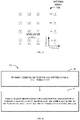
- 4 beam groups could be selected in the antenna array 300 0 as shown in FIG. 3A , which are groups 310 0 - 310 3 .
- the indices of the selected beam groups ⁇ r 1 (i), r 2 (i) ⁇ may be represent as ⁇ 0,0 ⁇ , ⁇ 0,2 ⁇ , ⁇ 1,2 ⁇ , ⁇ 2,3 ⁇ , respectively.
- the N 1 *N 2 beams within one group are not orthogonal.
- L orthogonal beams from 4 groups with same x 1 , x 2 value should be selected and number of bits for i 1,2 may be rewrote as
- the indices of the selected beam groups ⁇ r 1 (i), r 2 (i) ⁇ may be any P combinations from the set of ( ⁇ 0,0 ⁇ , ⁇ 0,1 ⁇ , ⁇ 0,2 ⁇ , ⁇ 0,3 ⁇ , ⁇ 1,0 ⁇ , ⁇ 1,1 ⁇ , ⁇ 1,2 ⁇ , ⁇ 1,3 ⁇ , ⁇ 2,0 ⁇ , ⁇ 2,1 ⁇ , ⁇ 2,2 ⁇ , ⁇ 2,3 ⁇ , ⁇ 3,0 ⁇ , ⁇ 3,1 ⁇ , ⁇ 3,2 ⁇ , ⁇ 3,3 ⁇ ) for implementing implementations of the present disclosure.
- P (for example. P may be 2 or 3 or 4 or 5 or 6) beam groups may be selected.
- the number of bits for i 1,2 may be no more than
- P (for example. P may be 2 or 3 or 4 or 5 or 6) beam groups may be selected.
- the number of bits for i 1,2 may be no more than
- P (for example. P may be 2 or 3 or 4 or 5 or 6) beam groups may be selected.
- the number of bits for i 1,2 may be no more than
- 4 beam groups could be selected in the antenna array 300 1 as shown in FIG. 3B , which are groups 320 0 - 320 3 .
- the indices of the selected beam groups ⁇ r 1 (i), r 2 (i) ⁇ may be represent as ⁇ 0,0 ⁇ , ⁇ 0,2 ⁇ , ⁇ 1,2 ⁇ , ⁇ 2,3 ⁇ , respectively. It should be understood that the indices of the selected beam groups ⁇ r 1 (i), r 2 (i) ⁇ is only for the purpose of illustration without suggesting any limitations.
- the indices of the selected beam groups ⁇ r 1 (i), r 2 (i) ⁇ may be any P combinations from the set of ( ⁇ 0,0 ⁇ , 0,11, ⁇ 0,2 ⁇ , ⁇ 0,3 ⁇ , ⁇ 1,0 ⁇ , ⁇ 1,1 ⁇ , ⁇ 1,2 ⁇ , ⁇ 1,3 ⁇ , ⁇ 2,0 ⁇ , ⁇ 2,1 ⁇ , ⁇ 2,2 ⁇ , ⁇ 2,3 ⁇ , ⁇ 3,0 ⁇ , ⁇ 3,1 ⁇ , ⁇ 3,2 ⁇ , ⁇ 3,3 ⁇ ) for implementing implementations of the present disclosure.
- the beams in corresponding position within 4 groups may represent as (a1,b1), (a2,b2), (a3,b3), (a4,b4).
- beam 321 0 and beam 321 1 are not orthogonal.
- the beams 321 0 - 321 3 of the beam groups 320 0 - 320 3 if the beam 321 0 of the beam group 320 0 is selected, then the beam 321 2 of the beam group 320 2 is selected.
- the beam 321 1 of the beam group 320 1 is selected, then the beam 321 3 of the beam group 320 3 is selected.
- 4 beam groups could be selected in the antenna array 300 2 as shown in FIG. 3B , which are groups 330 0 - 330 3 .
- the indices of the selected beam groups ⁇ r 1 (i), r 2 (i) ⁇ may be represent as ⁇ 0,0 ⁇ , 0,11, ⁇ 0,3 ⁇ , ⁇ 3,3 ⁇ , respectively. It should be understood that the indices of the selected beam groups ⁇ r 1 (i), r 2 (i) ⁇ is only for the purpose of illustration without suggesting any limitations.
- the indices of the selected beam groups ⁇ r 1 (i), r 2 (i) ⁇ may be any P combinations from the set of ( ⁇ 0,0 ⁇ , 0,11, ⁇ 0,2 ⁇ , ⁇ 0,3 ⁇ , ⁇ 1,0 ⁇ , ⁇ 1,1 ⁇ , ⁇ 1,2 ⁇ , 0,31, ⁇ 2,0 ⁇ , ⁇ 2,1 ⁇ , ⁇ 2,2 ⁇ , ⁇ 2,3 ⁇ , ⁇ 3,0 ⁇ , ⁇ 3,1 ⁇ , ⁇ 3,2 ⁇ , ⁇ 3,3 ⁇ ) for implementing implementations of the present disclosure.
- the beams in corresponding position within 4 groups may represent as (a1,b1), (a2,b2), (a3,b3), (a4,b4). As described above, if an index associated with a corresponding position of a beam may meet the Equations (4) or (5), then the beams are orthogonal to each other.
- beam 331 0 , beam 331 2 and beam 321 3 are orthogonal.
- the beams 331 0 - 331 3 of the beam groups 330 0 - 330 3 if the beam 331 0 of the beam group 330 0 is selected, then the beam 331 2 of the beam group 330 2 and the beam 321 3 of the beam group 330 2 are selected. If the beam 331 1 of the beam group 3301 is selected, there is no beam orthogonal to beam 331 1 in the other three beam groups.
- the indices of the 4 selected beam groups ⁇ r 1 (i), r 2 (i) ⁇ may be represent as ⁇ r 1 (0), r 2 (0) ⁇ , ⁇ r 1 (1), r 2 (1) ⁇ , ⁇ r 1 (2), r 2 (2) ⁇ , ⁇ r 1 (3), r 2 (3) ⁇ , respectively.
- the number of available beams for i 1,2 is M and the number of bits for i 1,2 may be no more than
- the number of available beams for i 1,2 is no more than 4, and the number of bits for i 1,2 may be no more than
- the number of available beams for i 1,2 is no more than 2, and the number of bits for i 1,2 may be no more than
- the terminal device does not assumed to be configured with L larger than 2.
- L can only be 2.
- the number of available beams for i 1,2 is no more than 3
- the number of bits for i 1,2 may be no more than
- the terminal device does not assumed to be configured with L larger than 3.
- L can only be 2 or 3.
- the number of available beams for i 1,2 is no more than 3
- the number of bits for i 1,2 may be no more than
- the terminal device does not assumed to be configured with L larger than 3.
- L can only be 2 or 3.
- the indices of the 4 selected beam groups ⁇ r 1 (i), r 2 (i) ⁇ may be represent as ⁇ r 1 (0), r 2 (0) ⁇ , ⁇ r 1 (1), r 2 (1) ⁇ , ⁇ r 1 (2), r 2 (2) ⁇ , ⁇ r 1 (3), r 2 (3) ⁇ , respectively, and the number of available beams for i 1,2 is M and the number of bits for i 1,2 may be no more than
- the number of available beams for i 1,2 is no more than 4, and the number of bits for i 1,2 may be no more than
- the number of available beams for i 1,2 is no more than 2, and the number of bits for i 1,2 may be no more than
- the terminal device does not assumed to be configured with L larger than 2.
- L can only be 2.
- the number of available beams for i 1,2 is no more than 3
- the number of bits for i 1,2 may be no more than
- the terminal device does not assumed to be configured with L larger than 3.
- L can only be 2 or 3.
- the number of available beams for i 1,2 is no more than 3 and the number of bits for i 1,2 may be no more than
- the terminal device does not assumed to be configured with L larger than 3.
- L can only be 2 or 3.
- the indices of the 4 selected beam groups ⁇ r 1 (i), r 2 (i) ⁇ may be represent as ⁇ r 1 (0), r 2 (0) ⁇ , ⁇ r 1 (1), r 2 (1) ⁇ , ⁇ r 1 (2), r 2 (2) ⁇ , ⁇ r 1 (3), r 2 (3) ⁇ , respectively, and the number of available beams for i 1,2 is M and the number of bits for i 1,2 may be no more than
- the number of available beams for i 1,2 is no more than 8
- the number of bits for i 1,2 may be no more than
- the number of available beams for i 1,2 is no more than 4, and the number of bits for i 1,2 may be no more than
- ⁇ log 2 ⁇ ( 4 L ) ⁇ ⁇ log 2 ⁇ ( 4 L ) ⁇ .
- the number of available beams for i 1,2 is no more than 6, and the number of bits for i 1,2 may be no more than
- ⁇ log 2 ⁇ ( 6 L ) ⁇ ⁇ log 2 ⁇ ( 6 L ) ⁇ .
- the number of available beams for i 1,2 is no more than 6, and the number of bits for i 1,2 may be no more than
- the indices of the 4 selected beam groups ⁇ r 1 (i), r 2 (i) ⁇ may be represent as ⁇ r 1 (0), r 2 (0) ⁇ , ⁇ r 1 (1), r 2 (1) ⁇ , ⁇ r 1 (2), r 2 (2) ⁇ , ⁇ r 1 (3), r 2 (3) ⁇ , respectively, and the number of available beams for i 1,2 is M and the number of bits for i 1,2 may be no more than
- the number of available beams for i 1,2 is no more than 16, and the number of bits for i 1,2 may be no more than
- the number of available beams for i 1,2 is no more than 8
- the number of bits for i 1,2 may be no more than
- ⁇ log 2 ⁇ ( 8 L ) ⁇ ⁇ log 2 ⁇ ( 8 L ) ⁇ .
- the number of available beams for i 1,2 is no more than 12, and the number of bits for i 1,2 may be no more than
- ⁇ log 2 ⁇ ( 1 ⁇ 2 L ) ⁇ ⁇ log 2 ⁇ ( 1 ⁇ 2 L ) ⁇ .
- the number of available beams for i 1,2 is no more than 12, and the number of bits for i 1,2 may be no more than
- the indices of the 4 selected beam groups ⁇ r 1 (i), r 2 (i) ⁇ may be represent as ⁇ r 1 (0), r 2 (0) ⁇ , ⁇ r 1 (1), r 2 (1) ⁇ , ⁇ r 1 (2), r 2 (2) ⁇ , ⁇ r 1 (3), r 2 (3) ⁇ , respectively, and the number of available beams for i 1,2 is M and the number of bits for i 1,2 may be no more than
- the number of available beams for i 1,2 is no more than 4, and the number of bits for i 1,2 may be no more than
- r 2 (i) are all from (0, 2) or all from (1,3), and three values of r 1 (i) are from (0, 2), and one value of r 1 (i) is from (1, 3), the number of available beams for i 1,2 is no more than 3, and the number of bits for i 1,2 may be no more than
- r 2 (i) are all from (0, 2) or all from (1,3), and one value of r 1 (i) is from (0, 2), and three values of r 1 (i) are from (1, 3), the number of available beams for i 1,2 is no more than 3, and the number of bits for i 1,2 may be no more than
- r 1 (i) are all from (0, 2) or all from (1,3), and three values of r 2 (i) are from (0, 2), and one value of r 2 (i) is from (1, 3), the number of available beams for i 1,2 is no more than 3, and the number of bits for i 1,2 may be no more than
- r 1 (i) are all from (0, 2) or all from (1,3), and one value of r 2 (i) is from (0, 2), and three values of r 2 (i) are from (1, 3), the number of available beams for i 1,2 is no more than 3, and the number of bits for i 1,2 may be no more than
- L can only be 2 or 3.
- the number of available beams for i 1,2 is no more than 2, and the number of bits for i 1,2 may be no more than
- the terminal device does not assumed to be configured with L larger than 2.
- L can only be 2.
- the number of available beams for i 1,2 is no more than 2, and the number of bits for i 1,2 may be no more than
- the terminal device does not assumed to be configured with L larger than 2.
- L can only be 2.
- the maximal number of available beams for i 1,2 may also be determined.
- the overhead for i 1,2 is not reduced.
- the total number of beams available for i 1,2 depends on the selected groups.
- M 6
- M 2
- the number of available beam groups K for the first PMI are no larger than O 1 *O 2 .
- the number of bits for i 1,1 is no more than ⁇ log 2 (O 1 *O 2 ) ⁇ .
- 4 beam groups could be selected in the antenna array 400 0 as shown in FIG. 4 , which are groups 410 0 - 410 3 .
- an index associated with a corresponding position of a beam may meet the Equations (4) or (5), then the beams are orthogonal to each other.
- a beam, beam 411 0 for example, will be selected from the beam group 410 0
- there are only other 7 beam groups of the 15 groups may include a beam orthogonal to beam 411 0 , namely beam groups 410 2 , 410 4 - 410 6 and 410 7 - 410 9 .
- the number of available beam groups K for i 1,1 is 8, which is less than the value of O 1 *O 2 .
- the overhead feedback for i 1,1 is reduced.
- the terminal device 120 may also obtains the second CBSR from RRC signaling received from the network device 110 , the second CBSR indicating a fifth number of a second beam groups selected from the set of beam and a sixth number of beams selected from the set of beams.
- the second CBSR may refer to a restriction of amplitude value for one beam.
- the indices of the 4 selected beam groups ⁇ r 1 (i), r 2 (i) ⁇ may be represent as ⁇ r 1 (0), r 2 (0) ⁇ , ⁇ r 1 (1), r 2 (1) ⁇ , ⁇ r 1 (2), r 2 (2) ⁇ , ⁇ r 1 (3), r 2 (3) ⁇ , respectively.
- the number of available beams groups for i 1,1 is K and the number of bits for i 1,1 may be no more than ⁇ log 2 (K) ⁇ .
- the values of r 2 (i) are all from (0, 2) or all from (1, 3)
- the number of available beams groups for i 1,1 is no more than 8
- the number of bits for i 1,1 may be no more than ⁇ log 2 (8) ⁇ .
- the number of available beams groups for i 1,1 is no more than 6, and the number of bits for i 1,1 may be no more than ⁇ log 2 (6) ⁇ .
- the number of available beams groups for i 1,1 is no more than 12, and the number of bits for i 1,1 may be no more than ⁇ log 2 (12) ⁇ .
- the indices of the 4 selected beam groups ⁇ r 1 (i), r 2 (i) ⁇ may be represent as ⁇ r 1 (0), r 2 (0) ⁇ , ⁇ r 1 (1), r 2 (1) ⁇ , ⁇ r 1 (2), r 2 (2) ⁇ , ⁇ r 1 (3), r 2 (3) ⁇ , respectively.
- the number of available beams groups for i 1,1 is K and the number of bits for i 1,1 may be no more than ⁇ log 2 (K) ⁇ .
- the values of r 2 (i) are all from (0, 2) or all from (1, 3)
- the number of available beams groups for i 1,1 is no more than 8
- the number of bits for i 1,1 may be no more than ⁇ log 2 (8) ⁇ .
- the values of r 1 (i) are all from (0, 2) or all from (1, 3)
- the number of available beams groups for i 1,1 is no more than 8
- the number of bits for i 1,1 may be no more than ⁇ log 2 (8) ⁇ .
- the number of available beams groups for i 1,1 is no more than 4, and the number of bits for i 1,1 may be no more than ⁇ log 2 (4) ⁇ .
- the indices of the 4 selected beam groups ⁇ r 1 (i), r 2 (i) ⁇ may be represent as ⁇ r 1 (0), r 2 (0) ⁇ , ⁇ r 1 (1), r 2 (1) ⁇ , ⁇ r 1 (2), r 2 (2) ⁇ , ⁇ r 1 (3), r 2 (3) ⁇ , respectively.
- the number of available beams groups for i 1,1 is K and the number of bits for i 1,1 may be no more than ⁇ log 2 (K) ⁇ .
- the number of available beams groups for i 1,1 is no more than 12, and the number of bits for i 1,1 may be no more than ⁇ log 2 (12) ⁇ .
- the terminal device may determine a third PMI based on the first and second PMIs and the second CBSR.
- the third PMI may indicates at least one wideband amplitude coefficient of a seventh number of beams determined based on the first and second PMIs and the second CBSR.
- the available number M of values for i 1,2 and the available number K of values for i 1,1 are determined.
- 4 beam groups could be selected in the antenna array.
- W the number of beams in the selected beam groups whose amplitude is not zero
- the beams with value of x, y are not available and would not be selected.
- Z is the number of pairs of (x,y) in the beam groups selected based on the second CBSR and satisfy W ⁇ L
- the number of available values for i 1,1 , namely K, and the number of available values for i 1,2 , namely M, may be further restricted by Z. In other words, the number of available values for i 1,1 is K ⁇ Z and the number of available values for i 1,2 is M ⁇ Z.
- an interval of beams selected for one terminal device should not be very large.
- the available number of beams from N 1 *N 2 for i 1,2 may be restricted though determining a range of interval of the orthogonal beams in an antenna array.
- FIG. 5 illustrates an antenna array 500 .
- the antenna array 500 there are 16 beam groups.
- the beams spaced apart from each other by O 1 are orthogonal to each other.
- a beam of beam group 510 0 is orthogonal to the corresponding beam in other beam groups of the antenna array 500 .
- the terminal device 120 may also determines a fourth PMI.
- the fourth PMI may indicate at least one subband amplitude coefficient of the seventh number of beams
- i 1,4,1 may be regarded a wideband indication for amplitude coefficient of each beam in L beams and i 2,2,1 may be regarded a subband indication of phase coefficient for the beams from 2L ⁇ 1 beams, whose wideband amplitude value are not zero, in a subband.
- M l represents the number of beams having of non-zero wideband amplitude coefficients.
- a CSI report may be include a first CSI part and a second CSI part.
- M l may be reported to the network device in the first CSI part.
- the wideband amplitude coefficients (that is, i 1,4,1 ) may be reported to the network device in the first CSI part.
- Table 3 shows the mapping order of CSI fields of the first CSI part.
- the overhead depends on the number of non-zero wideband amplitude coefficients. However, even if some wideband amplitude coefficients are not zero, those wideband amplitude coefficients are not large enough. Thus, for those wideband amplitude coefficients, there is no need to adjust the subband amplitude coefficients.
- a threshold may be set to further the number of non-zero wideband amplitude coefficients.
- the threshold may be any one of ⁇ square root over ( 1/64) ⁇ , ⁇ square root over ( 1/32) ⁇ , ⁇ square root over ( 1/16) ⁇ , ⁇ square root over (1 ⁇ 8) ⁇ , ⁇ square root over (1 ⁇ 4) ⁇ , ⁇ square root over (1 ⁇ 2) ⁇ and 1.
- the subband amplitude coefficient may be set to 1, and no reporting of i 2,2,1 and/or i 2,2,2 .
- threshold may be set to be ⁇ square root over (1 ⁇ 8) ⁇ .
- the terminal device 120 transmits the at least one PMI to the network device 120 .
- the at least one PMI is transmitted to the network device 120 via physical uplinks control channel (PUCCH).
- PUCCH physical uplinks control channel
- embodiments of the present disclosure provide a solution for reducing CSI feedback overhead.
- the feedback overhead for PMI associated with i 1,2 , i 1,1 , i 1,4,1 and i 2,1,1 is significantly reduced.
- FIG. 6 shows a flowchart of an example method 600 for reducing channel state information (CSI) feedback overhead in accordance with some embodiments of the present disclosure.
- the method 600 can be implemented at a network device 110 as shown in FIG. 1 .
- the method 600 will be described from the perspective of the network device 110 with reference to FIG. 1 .
- the network device 110 transmits a codebook configuration and a reference signal to a terminal device, the codebook configuration indicating at least one codebook subset restriction (CBSR).
- CBSR codebook subset restriction
- the network device 110 at least one precoding matrix indicator (PMI) associated with a plurality of beams of a set of beams between the terminal device and the network device selected at least partially based on the at least one CBSR, the at least one PMI is determined based on the reference signal by the terminal device.
- PMI precoding matrix indicator
- the network device 110 may determine a target beam from the at least one PMI, and transmit a signal to the terminal device via the target beam.
- FIG. 7 shows a process 700 for UCI transmission according to an implementation of the present disclosure.
- the process 700 will be described with reference to FIG. 1 .
- the process 700 may involve the network device 110 and the terminal device 120 in FIG. 1 .
- the network device 110 transmits ( 705 ) a codebook configuration and a reference signal to a terminal device 120 .
- the codebook configuration indicates at least one codebook subset restriction (CBSR).
- CBSR codebook subset restriction
- the terminal device 120 determines ( 710 ) at least one precoding matrix indicator (PMI) associated with a plurality of beams of a set of beams between the terminal device and the network device selected at least partially based on the at least one CBSR based on he at least one CBSR. For determining the at least one PMI associated with some certain beams or beam groups, the terminal device 120 obtains a number of antenna ports in a first and second dimensions of an antenna array of the network device 110 and oversampling factors corresponding to the number of antenna ports in a first and second dimensions of the antenna array of the network device 110 based on the RRC signaling received from the network device. Furthermore, the terminal device 120 obtains first and second CBSR.
- PMI precoding matrix indicator
- the terminal device 120 transmits ( 715 ) the at least one PMI to the network device 110 .
- the network device 110 determines ( 720 ) a target beam from the at least one PMI and transmits ( 725 ) a signal to the terminal device 120 via the target beam.
- embodiments of the present disclosure provide a solution for reducing CSI feedback overhead.
- the feedback overhead for PMI associated with i 1,2 , i 1,1 , i 1,4,1 and i 2,1,1 is significantly reduced.
- FIG. 8 is a simplified block diagram of a device 800 that is suitable for implementing embodiments of the present disclosure.
- the device 800 can be considered as a further example implementation of a network device 110 or a terminal device 120 as shown in FIG. 1 . Accordingly, the device 800 can be implemented at or as at least a part of the network device 110 or the terminal device 120 .
- the device 800 includes a processor 810 , a memory 820 coupled to the processor 810 , a suitable transmitter (TX) and receiver (RX) 840 coupled to the processor 810 , and a communication interface coupled to the TX/RX 840 .
- the memory 810 stores at least a part of a program 830 .
- the TX/RX 840 is for bidirectional communications.
- the TX/RX 840 has at least one antenna to facilitate communication, though in practice an Access Node mentioned in this application may have several ones.
- the communication interface may represent any interface that is necessary for communication with other network elements, such as X2 interface for bidirectional communications between eNBs, S1 interface for communication between a Mobility Management Entity (MME)/Serving Gateway (S-GW) and the eNB, Un interface for communication between the eNB and a relay node (RN), or Uu interface for communication between the eNB and a terminal device.
- MME Mobility Management Entity
- S-GW Serving Gateway
- Un interface for communication between the eNB and a relay node
- Uu interface for communication between the eNB and a terminal device.
- the program 830 is assumed to include program instructions that, when executed by the associated processor 810 , enable the device 800 to operate in accordance with the embodiments of the present disclosure, as discussed herein with reference to FIGS. 2 to 7 .
- the embodiments herein may be implemented by computer software executable by the processor 810 of the device 800 , or by hardware, or by a combination of software and hardware.
- the processor 810 may be configured to implement various embodiments of the present disclosure.
- a combination of the processor 810 and memory 810 may form processing means 850 adapted to implement various embodiments of the present disclosure.
- the memory 810 may be of any type suitable to the local technical network and may be implemented using any suitable data storage technology, such as a non-transitory computer readable storage medium, semiconductor-based memory devices, magnetic memory devices and systems, optical memory devices and systems, fixed memory and removable memory, as non-limiting examples. While only one memory 810 is shown in the device 800 , there may be several physically distinct memory modules in the device 800 .
- the processor 810 may be of any type suitable to the local technical network, and may include one or more of general purpose computers, special purpose computers, microprocessors, digital signal processors (DSPs) and processors based on multicore processor architecture, as non-limiting examples.
- the device 800 may have multiple processors, such as an application specific integrated circuit chip that is slaved in time to a clock which synchronizes the main processor.
- various embodiments of the present disclosure may be implemented in hardware or special purpose circuits, software, logic or any combination thereof. Some aspects may be implemented in hardware, while other aspects may be implemented in firmware or software which may be executed by a controller, microprocessor or other computing device. While various aspects of embodiments of the present disclosure are illustrated and described as block diagrams, flowcharts, or using some other pictorial representation, it will be appreciated that the blocks, apparatus, systems, techniques or methods described herein may be implemented in, as non-limiting examples, hardware, software, firmware, special purpose circuits or logic, general purpose hardware or controller or other computing devices, or some combination thereof.
- the present disclosure also provides at least one computer program product tangibly stored on a non-transitory computer readable storage medium.
- the computer program product includes computer-executable instructions, such as those included in program modules, being executed in a device on a target real or virtual processor, to carry out the process or method as described above with reference to any of FIGS. 2 o 11
- program modules include routines, programs, libraries, objects, classes, components, data structures, or the like that perform particular tasks or implement particular abstract data types.
- the functionality of the program modules may be combined or split between program modules as desired in various embodiments.
- Machine-executable instructions for program modules may be executed within a local or distributed device. In a distributed device, program modules may be located in both local and remote storage media.
- Program code for carrying out methods of the present disclosure may be written in any combination of one or more programming languages. These program codes may be provided to a processor or controller of a general purpose computer, special purpose computer, or other programmable data processing apparatus, such that the program codes, when executed by the processor or controller, cause the functions/operations specified in the flowcharts and/or block diagrams to be implemented.
- the program code may execute entirely on a machine, partly on the machine, as a stand-alone software package, partly on the machine and partly on a remote machine or entirely on the remote machine or server.
- the above program code may be embodied on a machine readable medium, which may be any tangible medium that may contain, or store a program for use by or in connection with an instruction execution system, apparatus, or device.
- the machine readable medium may be a machine readable signal medium or a machine readable storage medium.
- a machine readable medium may include but not limited to an electronic, magnetic, optical, electromagnetic, infrared, or semiconductor system, apparatus, or device, or any suitable combination of the foregoing.
- machine readable storage medium More specific examples of the machine readable storage medium would include an electrical connection having one or more wires, a portable computer diskette, a hard disk, a random access memory (RAM), a read-only memory (ROM), an erasable programmable read-only memory (EPROM or Flash memory), an optical fiber, a portable compact disc read-only memory (CD-ROM), an optical storage device, a magnetic storage device, or any suitable combination of the foregoing.
- RAM random access memory
- ROM read-only memory
- EPROM or Flash memory erasable programmable read-only memory
- CD-ROM portable compact disc read-only memory
- magnetic storage device or any suitable combination of the foregoing.
Applications Claiming Priority (1)
| Application Number | Priority Date | Filing Date | Title |
|---|---|---|---|
| PCT/CN2018/098659 WO2020024289A1 (en) | 2018-08-03 | 2018-08-03 | Methods and devices for reducing channel state information feedback overhead |
Publications (2)
| Publication Number | Publication Date |
|---|---|
| US20210306041A1 US20210306041A1 (en) | 2021-09-30 |
| US11438041B2 true US11438041B2 (en) | 2022-09-06 |
Family
ID=69231303
Family Applications (1)
| Application Number | Title | Priority Date | Filing Date |
|---|---|---|---|
| US17/264,623 Active US11438041B2 (en) | 2018-08-03 | 2018-08-03 | Methods and devices for reducing channel state information feedback overhead |
Country Status (3)
| Country | Link |
|---|---|
| US (1) | US11438041B2 (ja) |
| JP (2) | JP2022502878A (ja) |
| WO (1) | WO2020024289A1 (ja) |
Families Citing this family (5)
| Publication number | Priority date | Publication date | Assignee | Title |
|---|---|---|---|---|
| US11510077B2 (en) * | 2018-01-12 | 2022-11-22 | Lg Electronics Inc. | Method and user equipment for performing measurement by using multiple reception beams |
| US11522662B2 (en) * | 2020-04-30 | 2022-12-06 | Lenovo (Singapore) Pte. Ltd. | Method and user equipment for generating a channel state information feedback report including jointly encoded parameters from multiple layers |
| US11700049B2 (en) * | 2020-09-21 | 2023-07-11 | Qualcomm Incorporated | Techniques for beam switching in wireless communications |
| US11743750B2 (en) * | 2020-10-20 | 2023-08-29 | Rohde & Schwarz Gmbh & Co. Kg | Measuring device and method for testing CSI type II codebook compliance |
| WO2023133872A1 (en) * | 2022-01-17 | 2023-07-20 | Qualcomm Incorporated | Dynamic codebook subset restriction configurations |
Citations (13)
| Publication number | Priority date | Publication date | Assignee | Title |
|---|---|---|---|---|
| US20110249713A1 (en) * | 2010-04-07 | 2011-10-13 | David Hammarwall | Parameterized Codebook with Subset Restrictions for use with Precoding MIMO Transmissions |
| US20130107920A1 (en) * | 2010-07-12 | 2013-05-02 | Lg Electronics Inc. | Method and device for transmitting/receiving a signal by using a code book in a wireless communication system |
| US20130114656A1 (en) * | 2011-11-07 | 2013-05-09 | Motorola Mobility Llc | Method and apparatus for csi feedback for joint processing schemes in an orthogonal frequency division multiplexing communication system with coordinated multi-point transmission |
| US20160294454A1 (en) * | 2015-03-30 | 2016-10-06 | Samsung Electronics Co., Ltd | Method and apparatus for codebook design and signaling |
| US20160323022A1 (en) * | 2015-04-29 | 2016-11-03 | Samsung Electronics Co., Ltd | Codebook design and structure for advanced wireless communication systems |
| US20170041051A1 (en) | 2015-07-21 | 2017-02-09 | Samsung Electronics Co., Ltd | Higher rank codebooks for advanced wireless communication systems |
| CN108141317A (zh) | 2015-08-14 | 2018-06-08 | 瑞典爱立信有限公司 | 用于多用户叠加传输的多个csi报告 |
| US20180167117A1 (en) * | 2015-08-14 | 2018-06-14 | Huawei Technologies Co., Ltd. | Codebook configuration method and user equipment |
| CN108352888A (zh) | 2015-11-01 | 2018-07-31 | Lg电子株式会社 | 在无线通信系统中发送用于must传输的控制信息的方法及其装置 |
| US20180227029A1 (en) * | 2017-02-03 | 2018-08-09 | At&T Intellectual Property I, L.P. | Facilitation of computational complexity reduction for periodic and aperiodic channel state information reporting in 5g or other next generation network |
| US20180287682A1 (en) * | 2017-03-23 | 2018-10-04 | Samsung Electronics Co., Ltd. | Method and apparatus for transmitting data in wireless communication system |
| US20190028158A1 (en) * | 2015-07-23 | 2019-01-24 | Lg Electronics Inc. | Codebook-based signal transmission and reception method in multi-antenna wireless communication system and apparatus therefor |
| US20200195319A1 (en) * | 2017-06-14 | 2020-06-18 | Lg Electronics Inc. | Method for transmitting and receiving channel state information in wireless communication system and device for the same |
Family Cites Families (1)
| Publication number | Priority date | Publication date | Assignee | Title |
|---|---|---|---|---|
| JP2015111929A (ja) * | 2015-02-16 | 2015-06-18 | シャープ株式会社 | 基地局装置、端末装置、通信システムおよび通信方法 |
-
2018
- 2018-08-03 WO PCT/CN2018/098659 patent/WO2020024289A1/en active Application Filing
- 2018-08-03 JP JP2021505199A patent/JP2022502878A/ja active Pending
- 2018-08-03 US US17/264,623 patent/US11438041B2/en active Active
-
2023
- 2023-09-27 JP JP2023166272A patent/JP2023179576A/ja active Pending
Patent Citations (13)
| Publication number | Priority date | Publication date | Assignee | Title |
|---|---|---|---|---|
| US20110249713A1 (en) * | 2010-04-07 | 2011-10-13 | David Hammarwall | Parameterized Codebook with Subset Restrictions for use with Precoding MIMO Transmissions |
| US20130107920A1 (en) * | 2010-07-12 | 2013-05-02 | Lg Electronics Inc. | Method and device for transmitting/receiving a signal by using a code book in a wireless communication system |
| US20130114656A1 (en) * | 2011-11-07 | 2013-05-09 | Motorola Mobility Llc | Method and apparatus for csi feedback for joint processing schemes in an orthogonal frequency division multiplexing communication system with coordinated multi-point transmission |
| US20160294454A1 (en) * | 2015-03-30 | 2016-10-06 | Samsung Electronics Co., Ltd | Method and apparatus for codebook design and signaling |
| US20160323022A1 (en) * | 2015-04-29 | 2016-11-03 | Samsung Electronics Co., Ltd | Codebook design and structure for advanced wireless communication systems |
| US20170041051A1 (en) | 2015-07-21 | 2017-02-09 | Samsung Electronics Co., Ltd | Higher rank codebooks for advanced wireless communication systems |
| US20190028158A1 (en) * | 2015-07-23 | 2019-01-24 | Lg Electronics Inc. | Codebook-based signal transmission and reception method in multi-antenna wireless communication system and apparatus therefor |
| CN108141317A (zh) | 2015-08-14 | 2018-06-08 | 瑞典爱立信有限公司 | 用于多用户叠加传输的多个csi报告 |
| US20180167117A1 (en) * | 2015-08-14 | 2018-06-14 | Huawei Technologies Co., Ltd. | Codebook configuration method and user equipment |
| CN108352888A (zh) | 2015-11-01 | 2018-07-31 | Lg电子株式会社 | 在无线通信系统中发送用于must传输的控制信息的方法及其装置 |
| US20180227029A1 (en) * | 2017-02-03 | 2018-08-09 | At&T Intellectual Property I, L.P. | Facilitation of computational complexity reduction for periodic and aperiodic channel state information reporting in 5g or other next generation network |
| US20180287682A1 (en) * | 2017-03-23 | 2018-10-04 | Samsung Electronics Co., Ltd. | Method and apparatus for transmitting data in wireless communication system |
| US20200195319A1 (en) * | 2017-06-14 | 2020-06-18 | Lg Electronics Inc. | Method for transmitting and receiving channel state information in wireless communication system and device for the same |
Non-Patent Citations (5)
| Title |
|---|
| Huawei et al., "General framework for CSI acquisition and beam management", 3GPP TSG RAN WGI Meeting #90, R1-1712226, Aug. 25, 2017, 10 pages. |
| International Search Report for PCT/CN2018/098659 dated Mar. 27, 2019 [PCT/ISA/210]. |
| LG Electronics, "Discussions on CSI reporting contents", 3GPP TSG RAN WG1 Meeting #90, R1-1713145, Aug. 25, 2017, 5 pages. |
| Notification of Reason for Refusal dated Jul. 5, 2022 in Japanese Application 2021-505199. |
| Written Opinion for PCT/CN2018/098659 dated Mar. 27, 2019 [PCT/ISA/237]. |
Also Published As
| Publication number | Publication date |
|---|---|
| JP2023179576A (ja) | 2023-12-19 |
| WO2020024289A1 (en) | 2020-02-06 |
| US20210306041A1 (en) | 2021-09-30 |
| JP2022502878A (ja) | 2022-01-11 |
Similar Documents
| Publication | Publication Date | Title |
|---|---|---|
| US11683215B2 (en) | System and method for communications beam recovery | |
| US11438041B2 (en) | Methods and devices for reducing channel state information feedback overhead | |
| US20200014455A1 (en) | Beam information feedback method and apparatus, and configuration information feedback method and apparatus | |
| US10419090B2 (en) | Method for precoding matrix indicator feedback and apparatus | |
| US20220255598A1 (en) | Multi-trp codebook | |
| US10205498B2 (en) | User equipment and codebook search method for 4Tx dual codebook (ran1) | |
| US20210306123A1 (en) | Uplink transmission | |
| US20220330068A1 (en) | Methods, devices and computer storage media for csi feedback | |
| US10567054B2 (en) | Channel state information sending method and receiving method, apparatus, and system | |
| US20230216567A1 (en) | Methods and devices for channel state information transmission | |
| US20200007213A1 (en) | Method of csi reporting | |
| US20220239362A1 (en) | Method, device and computer readable medium for uplink control information transmission | |
| JP6583409B2 (ja) | 無線通信制御方法、無線通信システム、受信装置および送信装置 | |
| US20220377747A1 (en) | Method, device and computer readable medium for channel quality measurement | |
| CN114071557A (zh) | 动态信道状态信息报告的方法、设备、装置和存储介质 | |
| KR102524774B1 (ko) | 채널 상태 정보를 결정하기 위한 방법 및 장치 | |
| WO2022261873A1 (en) | Channel state information reporting | |
| KR102522768B1 (ko) | 이동 통신 시스템에서 다중 빔포밍을 이용한 데이터 통신 방법 및 장치 | |
| WO2020107423A1 (en) | Method, device and computer readable medium for sinr measurement | |
| CN117044140A (zh) | 用于通信的方法、设备和计算机可读存储介质 | |
| CN117413482A (zh) | 用于通信的方法、设备和计算机存储介质 |
Legal Events
| Date | Code | Title | Description |
|---|---|---|---|
| AS | Assignment |
Owner name: NEC CORPORATION, JAPAN Free format text: ASSIGNMENT OF ASSIGNORS INTEREST;ASSIGNORS:GAO, YUKAI;WANG, GANG;REEL/FRAME:055082/0984 Effective date: 20191218 |
|
| FEPP | Fee payment procedure |
Free format text: ENTITY STATUS SET TO UNDISCOUNTED (ORIGINAL EVENT CODE: BIG.); ENTITY STATUS OF PATENT OWNER: LARGE ENTITY |
|
| STPP | Information on status: patent application and granting procedure in general |
Free format text: NON FINAL ACTION MAILED |
|
| STPP | Information on status: patent application and granting procedure in general |
Free format text: RESPONSE TO NON-FINAL OFFICE ACTION ENTERED AND FORWARDED TO EXAMINER |
|
| STPP | Information on status: patent application and granting procedure in general |
Free format text: NOTICE OF ALLOWANCE MAILED -- APPLICATION RECEIVED IN OFFICE OF PUBLICATIONS |
|
| STPP | Information on status: patent application and granting procedure in general |
Free format text: WITHDRAW FROM ISSUE AWAITING ACTION |
|
| STPP | Information on status: patent application and granting procedure in general |
Free format text: NOTICE OF ALLOWANCE MAILED -- APPLICATION RECEIVED IN OFFICE OF PUBLICATIONS |
|
| STCF | Information on status: patent grant |
Free format text: PATENTED CASE |