US11437797B2 - Bracket for electrical devices - Google Patents
Bracket for electrical devices Download PDFInfo
- Publication number
- US11437797B2 US11437797B2 US17/026,566 US202017026566A US11437797B2 US 11437797 B2 US11437797 B2 US 11437797B2 US 202017026566 A US202017026566 A US 202017026566A US 11437797 B2 US11437797 B2 US 11437797B2
- Authority
- US
- United States
- Prior art keywords
- bracket
- leg
- support members
- flange
- central opening
- Prior art date
- Legal status (The legal status is an assumption and is not a legal conclusion. Google has not performed a legal analysis and makes no representation as to the accuracy of the status listed.)
- Active
Links
Images


Classifications
-
- H—ELECTRICITY
- H02—GENERATION; CONVERSION OR DISTRIBUTION OF ELECTRIC POWER
- H02G—INSTALLATION OF ELECTRIC CABLES OR LINES, OR OF COMBINED OPTICAL AND ELECTRIC CABLES OR LINES
- H02G3/00—Installations of electric cables or lines or protective tubing therefor in or on buildings, equivalent structures or vehicles
- H02G3/02—Details
- H02G3/08—Distribution boxes; Connection or junction boxes
- H02G3/12—Distribution boxes; Connection or junction boxes for flush mounting
- H02G3/123—Distribution boxes; Connection or junction boxes for flush mounting in thin walls
- H02G3/126—Distribution boxes; Connection or junction boxes for flush mounting in thin walls with supporting means for mounting on a single wall stud
-
- H—ELECTRICITY
- H02—GENERATION; CONVERSION OR DISTRIBUTION OF ELECTRIC POWER
- H02G—INSTALLATION OF ELECTRIC CABLES OR LINES, OR OF COMBINED OPTICAL AND ELECTRIC CABLES OR LINES
- H02G3/00—Installations of electric cables or lines or protective tubing therefor in or on buildings, equivalent structures or vehicles
- H02G3/02—Details
- H02G3/08—Distribution boxes; Connection or junction boxes
- H02G3/12—Distribution boxes; Connection or junction boxes for flush mounting
- H02G3/123—Distribution boxes; Connection or junction boxes for flush mounting in thin walls
- H02G3/125—Distribution boxes; Connection or junction boxes for flush mounting in thin walls with supporting bar extending between two separate studs of a wall frame
-
- H—ELECTRICITY
- H02—GENERATION; CONVERSION OR DISTRIBUTION OF ELECTRIC POWER
- H02G—INSTALLATION OF ELECTRIC CABLES OR LINES, OR OF COMBINED OPTICAL AND ELECTRIC CABLES OR LINES
- H02G3/00—Installations of electric cables or lines or protective tubing therefor in or on buildings, equivalent structures or vehicles
- H02G3/02—Details
- H02G3/08—Distribution boxes; Connection or junction boxes
- H02G3/081—Bases, casings or covers
Definitions
- the present disclosure relates to mounting brackets, and particularly to mounting brackets for supporting electrical boxes and devices.
- a gang or junction box may be secured to a stud or support beam inside of the wall or ceiling.
- the electrical device is then secured in the box in electrical communication with one or more electrical conductors so that the electrical device extends or protrudes from the wall or ceiling. Any exposed portions of the electrical conductor and its connection to the electrical device may be shielded within the box.
- a bracket for supporting at least one electrical device includes a first portion including a flange oriented in a first plane and at least one second portion including a leg oriented in a second plane substantially parallel to and offset from the first plane. Each second portion is configured to be coupled to the at least one electrical device.
- a bracket for supporting at least one electrical device in another aspect, includes a first portion and at least one second portion.
- the first portion includes a flange extending between a first end and a second end, and the flange defines a central opening.
- the at least one second portion includes a leg connected to the first portion and extending at least partially between the first end and the second end. Each second portion provides multiple positions at which the at least one electrical device can be supported.
- a bracket for supporting at least one electrical device between a first support member and a second support member.
- the bracket includes a first end configured to be secured to a forward surface of the first support member, a second end configured to be secured to a forward surface of the second support member, a first portion, and at least one second portion.
- the bracket defines a longitudinal axis extending between the first end and the second end.
- the first portion includes a flange oriented in a first plane positioned proximate the forward surface of the first support member and the forward surface of the second support member.
- the first portion is positioned between the first end and the second end.
- the at least one second portion includes a leg oriented in a second plane. The leg is recessed relative to the first portion such that the second plane is substantially parallel to and offset from the first plane.
- the leg is configured to be coupled to the at least one electrical device.
- FIG. 1 is a perspective view of a bracket.
- FIG. 2 is a plan view of the bracket of FIG. 1 .
- FIG. 3 is an end view of the bracket of FIG. 1 .
- FIG. 4 is a side view of the bracket of FIG. 1 .
- FIG. 5 is a plan view of a blank prior to forming the bracket of FIG. 1 .
- FIG. 6 illustrates a perspective of the bracket of FIG. 1 supporting an electrical box and a mud ring.
- FIG. 7 is a plan view of the bracket of FIG. 1 supporting a plurality of electrical boxes and mud rings.
- FIG. 8 is a top view of the bracket of FIG. 7 .
- FIG. 9 is section view of the bracket of FIG. 7 , viewed along section 9 - 9 .
- FIG. 10 is an enlarged side view of portion 10 - 10 of FIG. 9 .
- FIG. 11 is a plan view of the bracket of FIG. 1 supporting a plurality of electrical boxes and a mud ring.
- FIG. 12 is a plan view of the bracket of FIG. 1 supporting a plurality of electrical boxes and a plurality of mud rings.
- FIG. 13 is a section view of the bracket of FIG. 12 viewed along section 13 - 13 .
- FIG. 14 is a perspective view of a bracket according to another embodiment.
- FIG. 15 is a plan view of the bracket of FIG. 14 .
- FIG. 16 is an end view of the bracket of FIG. 14 .
- FIG. 17 is a side view of the bracket of FIG. 14 .
- FIG. 18 is a plan view of a blank prior to forming the bracket of FIG. 14 .
- FIG. 19 is a plan view of the bracket of FIG. 14 supporting a plurality of electrical boxes and mud rings.
- FIG. 20 is a plan view of the bracket of FIG. 14 supporting a plurality of electrical boxes.
- FIG. 21 is a plan view of the bracket of FIG. 14 supporting a plurality of electrical boxes.
- FIG. 22 is a perspective view of a bracket according to another embodiment.
- FIG. 23 is a plan view of the bracket of FIG. 22 .
- FIG. 24 is an end view of the bracket of FIG. 22 .
- FIG. 25 is a side view of the bracket of FIG. 22 .
- FIG. 26 is a section view of the bracket of FIG. 22 viewed along section 26 - 26 .
- FIG. 27 is a plan view of a portion of the bracket of FIG. 22 .
- FIG. 28 is an end view of a portion of the bracket of FIG. 22 .
- FIG. 29 is a perspective view of a bracket according to another embodiment.
- FIG. 30 is a plan view of the bracket of FIG. 29 .
- FIG. 31 is an end view of the bracket of FIG. 29 .
- FIG. 32 is a side view of the bracket of FIG. 29 .
- FIG. 33 is a plan view of a blank prior to forming the bracket of FIG. 29 .
- FIG. 34 is a plan view of the bracket of FIG. 29 supporting an electrical box and a mud ring.
- FIG. 35 is a top view of the bracket, electrical box, and mud ring of FIG. 34 .
- FIG. 36 is a plan view of the bracket of FIG. 29 supporting an electrical box.
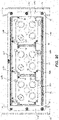
- FIG. 37 is a plan view of the bracket of FIG. 29 supporting an electrical box.
- FIG. 38 is a plan view of a pair of brackets of FIG. 29 supported on a common stud and each supporting an electrical box and mud ring.
- FIG. 39 is a top view of the pair of brackets, electrical boxes, mud rings, and stud of FIG. 38 .
- FIGS. 1-4 show a bracket 10 for supporting electrical devices.
- the bracket 10 includes an elongated first portion or flange 22 , and a pair of second portions 26 connected to the flange 22 .
- the flange 22 is oriented in a first plane and extends around an opening 30 .
- the flange 22 has a rectangular shape and includes a pair of end portions 34 and a pair of side portions 38 extending between the pair of end portions 34 .
- Each end portion 34 may include holes 42 ( FIG. 2 ) for coupling the flange 22 to a stud 50 ( FIG. 7 ).
- a longitudinal axis 14 of the bracket 10 extends between the end portions 34 .
- Each second portion 26 is positioned within the opening 30 .
- the second portion 26 includes a first leg 58 connected to one of the side portions 38 of the flange 22 and a second leg 62 coupled to the first leg 58 .
- the second legs 62 are oriented in a second plane offset from the first plane of the flange 10 .
- Apertures 68 for mounting an electrical device are formed on each second leg 62 .
- the apertures 68 may be formed as keyhole apertures having a round hole 74 and an elongated slot 78 extending laterally from the round hole 74 .
- the apertures 68 are aligned in a longitudinal direction and extend along a portion of the second leg 62 between the end portions 34 of the flange 22 .
- One of the second portions 26 a may include an aperture 68 a positioned adjacent one of the flange end portions 34 a , with the other apertures 68 a positioned sequentially along a portion of the second leg 62 a .
- the other second portion 26 b may include an aperture 68 b positioned adjacent the opposite end portion 34 b of the flange 22 , with the other apertures 68 b positioned sequentially along a portion of the other second leg 62 b , such that the apertures 68 b extend from alternate end portions 34 .
- the apertures 68 provide multiple positions at which an electrical box 70 and mud ring 72 may be attached.
- FIG. 5 shows a blank 82 before the bracket 10 is formed.
- the second portions 26 are initially formed coplanar with the flange 22 and are subsequently bent into the opening 30 .
- each second portion 26 is bent such that the second leg 62 is connected to the first leg 58 by a longitudinal channel 86 ( FIG. 3 ) extending along the length of the second portion 26 .
- the channel 86 provides additional rigidity. In some embodiments, the channel 86 also assists in centering or locating the electrical box 70 ( FIG. 6 ) with respect to the bracket 10 .
- FIGS. 7-9 show the bracket 10 coupled between two support members or studs 50 , and three electrical boxes 70 and three mud rings 72 are secured to the bracket 10 in multiple locations. It is understood that, in some embodiments, a different number of electrical boxes 70 and mud rings 72 may be secured to the bracket 10 , and the electrical boxes 70 and mud rings 72 may be secured in other locations. That is, the boxes 70 and mud rings 72 may be secured to the bracket 10 at positions between the boxes 70 and mud rings 72 shown in FIG. 7 .
- fasteners 90 extend through the holes 42 in each flange end portion 34 and into one of the studs 50 .
- the end portions 34 are positioned between the studs 50 and a wall material 94 (e.g., drywall— FIGS. 8 and 9 ).
- Electrical boxes 70 FIG. 8
- mud rings 72 FIG. 7
- the electrical boxes 70 are secured to the second portion 26 via fasteners 98 clamping onto an edge of the second leg 62 .
- the box 70 is a 4-inch box.
- FIG. 11 illustrates another embodiment in which each electrical box 70 is secured to the second portion 62 by fasteners 98 extending through the apertures 68 of the second legs 62 .
- the fasteners 98 may be inserted through the round hole 74 of the mounting apertures 68 and then slid along the elongated slot 78 until the electrical box 70 is in a desired position.
- FIGS. 12 and 13 illustrate another embodiment in which each mud ring 72 is secured to one of the electrical boxes 70 by fasteners 98 (e.g., box screws) extending through the opening 30 of the bracket 10 .
- the fasteners 98 are tightened such that the boxes 70 and mud rings 72 are clamped onto opposite sides of the second leg 62 . As shown in FIG.
- the channel 86 assists in centering each electrical box 70 in a vertical direction (i.e., aligning the electrical box 70 with a longitudinal axis of the bracket 10 ).
- the box 70 is a 4 11/16′′ box.
- FIGS. 14-17 illustrate a bracket 210 according to another embodiment.
- the bracket 210 is similar to the bracket 10 described above with respect to FIGS. 1-13 , and for the sake of brevity only differences are described herein. Similar features are identified with similar features, plus 200 .
- each second leg 262 includes tabs 264 extending into the opening 230 .
- the bracket 210 includes apertures 268 having various shapes.
- some mounting apertures include opened ended slots 268 a formed along edges of tabs 264 on one of the second portions 226 , and keyhole slots 268 b formed at an angle relative to tabs 264 on an opposite side of the bracket 210 .
- joined mounting apertures 268 c may be formed on each second leg 262 and may be formed as two key hole slots positioned in mirrored relationship in which the elongated slot portions are joined to one another.
- FIG. 18 shows a blank 282 before the bracket 210 is formed.
- the second portions 226 are initially formed coplanar with the flange 222 and are subsequently bent into the opening 230 .
- Each second portion 226 is bent such that a second leg 262 is connected to a first leg 258 by a longitudinal channel 286 ( FIG. 16 ) extending along the length of the second portion 226 .
- the channel 286 provides additional rigidity and assists in locating the electrical boxes 70 ( FIGS. 20 and 21 ) and mud rings 72 along a centerline of the bracket 210 .
- FIG. 19 illustrates the bracket 210 coupled between two studs 50 .
- Electrical boxes 70 and mud rings 72 are secured to the bracket 210 in multiple locations.
- the boxes 70 and mud rings 72 may be coupled to one another by one or more fasteners 98 , and threading the fasteners may cause the boxes 70 and mud rings 72 to clamp or exert a compressive force on the second portion 226 .
- the fasteners 98 may engage at least an edge of the second portion 226 .
- the apertures 268 may provide multiple fixed or discrete positions at which the box 70 and mud ring 72 may be secured.
- the electrical boxes 70 are secured by fasteners 98 extending through the slots 268 a , 268 b formed on the tabs 264 , and the mud rings 72 are secured via the same fasteners 98
- FIG. 20 shows the electrical boxes 70 secured to the second portion 226 by fasteners 98 (e.g., screws) extending through a center of the bracket 210
- FIG. 21 shows the electrical boxes 70 secured to the second portion 226 by fasteners 98 (e.g., screws) extending through the joined mounting apertures 268 c.
- FIGS. 22-26 illustrate a bracket 410 according to another embodiment.
- the bracket 410 is similar to the bracket 10 described above with respect to FIGS. 1-13 , and for the sake of brevity only differences are described herein. Similar features are identified with similar features, plus 400 .
- the bracket 410 is formed as two separate members 420 a , 420 b slidably engaging one another.
- the side portions 438 of the flange 422 and the second portions 426 of each member 420 a , 420 b overlap the side portions 438 and second portions 426 of one another and permit sliding movement relative to one another.
- One side portion 438 a of the first member 420 a is received within an associated side portion 438 b of the second member 420 b
- the other side portion 438 b of the first member 420 a receives the other side portion 438 b of the second member 420 b .
- the slidable connection between the members 420 a , 420 b permits the length of the bracket 410 to be adjusted to accommodate varying distances between adjacent studs.
- the members 420 a , 420 b are identical to each other.
- the second portion 426 of each member 420 a , 420 b may include apertures for securing electrical boxes and mud rings to the bracket 410 .
- FIGS. 29-32 illustrate a bracket 610 according to another embodiment.
- the bracket 610 is similar to the bracket 10 described above with respect to FIGS. 1-13 , and for the sake of brevity only differences are described herein. Similar features are identified with similar features, plus 600 .
- the bracket 610 has a shorter length than the bracket 210 described above.
- the bracket 610 accommodates a single electrical box 70 ( FIG. 34 ) and mud ring 72 .
- Each second leg 662 includes tabs 664 extending into the opening 630 .
- the second portion 626 includes mounting apertures 668 having various shapes.
- the apertures 668 include opened ended slots 668 a formed along edges of tabs 664 on one second portion 626 of the bracket 610 , and keyhole slots 668 b formed at an angle relative to tabs 664 on an opposite second portion 626 of the bracket 610 .
- joined mounting apertures 668 c may be formed on each second leg 626 and may be formed as two key hole slots positioned in mirrored relationship in which the elongated slot portions are joined to one another.
- FIG. 33 shows a blank 682 before the bracket 610 is formed.
- the second portions 626 are initially formed coplanar with the flange 622 and are subsequently bent into the opening 630 .
- Each second portion 626 is bent such that a second leg 626 is connected to a first leg 658 by a longitudinal channel 686 ( FIG. 31 ) extending along the length of the second portion 626 .
- the channel 686 provides additional rigidity and assists in locating the electrical boxes 70 ( FIG. 34 ) and mud rings 72 along a lateral centerline of the bracket 610 .
- FIGS. 34 and 35 illustrate the bracket 610 coupled to a stud 50 .
- An electrical box 70 and mud ring 72 is secured to the bracket 610 .
- the electrical box 70 is secured by fasteners 98 extending through apertures 668 a , 668 b formed on the tabs 664 , and the mud rings 72 are secured via the same fasteners 98 .
- FIG. 36 shows the electrical boxes 70 secured to the second portion 626 by fasteners 98 (e.g., screws) extending through the joined mounting apertures 668 c .
- FIG. 37 shows the electrical boxes 70 secured to the second portions 626 by fasteners 98 (e.g., screws) extending through a center of the bracket 610 .
- FIGS. 38 and 39 illustrate a pair of brackets 610 coupled to a common stud 50 , with one bracket 610 positioned on each side of the stud 50 .
Landscapes
- Engineering & Computer Science (AREA)
- Architecture (AREA)
- Civil Engineering (AREA)
- Structural Engineering (AREA)
- Connection Or Junction Boxes (AREA)
Abstract
Description
Claims (18)
Priority Applications (1)
| Application Number | Priority Date | Filing Date | Title |
|---|---|---|---|
| US17/026,566 US11437797B2 (en) | 2017-03-10 | 2020-09-21 | Bracket for electrical devices |
Applications Claiming Priority (3)
| Application Number | Priority Date | Filing Date | Title |
|---|---|---|---|
| US201762469862P | 2017-03-10 | 2017-03-10 | |
| US15/917,049 US10784666B2 (en) | 2017-03-10 | 2018-03-09 | Bracket for electrical devices |
| US17/026,566 US11437797B2 (en) | 2017-03-10 | 2020-09-21 | Bracket for electrical devices |
Related Parent Applications (1)
| Application Number | Title | Priority Date | Filing Date |
|---|---|---|---|
| US15/917,049 Continuation US10784666B2 (en) | 2017-03-10 | 2018-03-09 | Bracket for electrical devices |
Publications (2)
| Publication Number | Publication Date |
|---|---|
| US20210006055A1 US20210006055A1 (en) | 2021-01-07 |
| US11437797B2 true US11437797B2 (en) | 2022-09-06 |
Family
ID=63445071
Family Applications (2)
| Application Number | Title | Priority Date | Filing Date |
|---|---|---|---|
| US15/917,049 Active US10784666B2 (en) | 2017-03-10 | 2018-03-09 | Bracket for electrical devices |
| US17/026,566 Active US11437797B2 (en) | 2017-03-10 | 2020-09-21 | Bracket for electrical devices |
Family Applications Before (1)
| Application Number | Title | Priority Date | Filing Date |
|---|---|---|---|
| US15/917,049 Active US10784666B2 (en) | 2017-03-10 | 2018-03-09 | Bracket for electrical devices |
Country Status (2)
| Country | Link |
|---|---|
| US (2) | US10784666B2 (en) |
| CA (1) | CA2997810A1 (en) |
Families Citing this family (11)
| Publication number | Priority date | Publication date | Assignee | Title |
|---|---|---|---|---|
| US10784666B2 (en) * | 2017-03-10 | 2020-09-22 | Hubbell Incorporated | Bracket for electrical devices |
| US11473721B2 (en) | 2019-06-03 | 2022-10-18 | Erico International Corporation | Mounting bracket for electrical boxes |
| USD1039368S1 (en) | 2020-04-01 | 2024-08-20 | Erico International Corporation | Bracket with a keyhole pattern |
| USD983147S1 (en) | 2021-02-19 | 2023-04-11 | Erico International Corporation | Electrical bracket |
| USD1019352S1 (en) | 2021-04-30 | 2024-03-26 | Erico International Corporation | Electrical bracket with hole pattern |
| USD1024975S1 (en) | 2021-05-13 | 2024-04-30 | Erico International Corporation | Electrical bracket with hole pattern |
| US11729925B2 (en) | 2021-06-15 | 2023-08-15 | Erico International Corporation | Mounting bracket with angled mounting openings for electrical boxes |
| US12292159B2 (en) | 2021-11-04 | 2025-05-06 | Erico International Corporation | Between-stud bracket with auto-height system |
| WO2023159015A2 (en) * | 2022-02-17 | 2023-08-24 | Hubbell Incorporated | Cover plate for electrical boxes |
| US12224570B2 (en) * | 2022-04-22 | 2025-02-11 | Evergreen Innovation Group, LLC | Unibracket systems |
| KR102689859B1 (en) * | 2023-11-27 | 2024-07-30 | 주식회사 아이엠테크 | Electric wiring box installation support for lightweight partitions |
Citations (33)
| Publication number | Priority date | Publication date | Assignee | Title |
|---|---|---|---|---|
| US4723746A (en) | 1987-07-27 | 1988-02-09 | Temco Electric Products Company Inc. | Electrical box mounting bracket |
| US4964525A (en) | 1989-09-21 | 1990-10-23 | G.B. Electrical Inc. | Electrical box mounting bracket |
| US5221814A (en) | 1991-08-02 | 1993-06-22 | Amp Incorporated | Blind mounting face plate and anchor means |
| US5405111A (en) * | 1993-10-20 | 1995-04-11 | Medlin, Jr.; Lewis B. | Bracket for anchoring apparatus between wall studs |
| US5516068A (en) | 1992-07-31 | 1996-05-14 | Rice; Frank | Device support bracket |
| US5927667A (en) | 1996-09-27 | 1999-07-27 | Hubbell Incorporated | Electrical box mounting bracket |
| US5931425A (en) * | 1997-07-01 | 1999-08-03 | Oliva; John H. | Apparatus and method for mounting and stabilizing electrical junction boxes between wall studs |
| US6376770B1 (en) | 2000-02-28 | 2002-04-23 | Douglas Hyde | Quick connecting universal electrical box and wiring system |
| US6545214B2 (en) * | 2001-02-05 | 2003-04-08 | Michael J. Russell | Building utility upgrading device and method |
| US6590155B2 (en) * | 2001-04-25 | 2003-07-08 | Paul A. Vrame | Floor stand for mounting electrical box and for supporting conduit |
| US6666419B1 (en) * | 1999-11-23 | 2003-12-23 | 3244 Corporation | Bracket assembly for mounting electrical box between two building studs |
| US6803521B2 (en) * | 2001-04-25 | 2004-10-12 | Illini Electrical Sales, Inc. | Floor stand having parallel uprights of adjustable lengths, for electrical box having plaster ring |
| US20050067546A1 (en) | 2003-09-29 | 2005-03-31 | Cong Dinh | Mounting bracket for an electrical box |
| US20050067541A1 (en) | 2003-09-29 | 2005-03-31 | Cong Dinh | Flexible conduit support |
| US20050176278A1 (en) * | 2003-12-31 | 2005-08-11 | Cheatham James F. | Sliding clip electrical connection box mounting bracket |
| US7355118B1 (en) * | 2004-09-20 | 2008-04-08 | Arlington Industries, Inc. | Electrical box mounting assembly |
| US7591385B2 (en) * | 2004-05-06 | 2009-09-22 | Dr. Brooks Innovations, Llc | System for holding implements |
| US20100006723A1 (en) | 2008-07-11 | 2010-01-14 | Frank Yan | Universal Support Bracket for Electrical Junction Box |
| US20100270446A1 (en) * | 2009-04-28 | 2010-10-28 | Phillips Bruce G | Universal Adjustable Box Bracket |
| US20120031640A1 (en) | 2010-08-05 | 2012-02-09 | Hubbell Incorporated | Universal cover plate assembly |
| US8378213B1 (en) | 2003-03-14 | 2013-02-19 | Fabworks, Llc | Adjustable floor bracket articles and methods |
| US8403289B1 (en) | 2008-10-15 | 2013-03-26 | Eric R. Rinderer | Universal electric box mounting device |
| US20140103180A1 (en) | 2012-10-15 | 2014-04-17 | Erico International Corporation | Electrical box mounting bracket with rails |
| US20140263865A1 (en) | 2013-03-15 | 2014-09-18 | Cooper Technologies Company | Floor stand system for mounting an electrical box |
| US20150001357A1 (en) * | 2013-06-27 | 2015-01-01 | Thomas & Betts International, Inc. | Adjustable bracket assembly |
| US9252579B2 (en) | 2013-03-14 | 2016-02-02 | Hubbell Incorporated | Electrical box cover assembly |
| US20160099555A1 (en) | 2014-10-06 | 2016-04-07 | Saeed Nikayin | Universal Box Mounting Adapter and System |
| US20160241008A1 (en) | 2015-02-13 | 2016-08-18 | Hubbell Incorporated | Mounting bracket with far side support |
| US20160360629A1 (en) | 2014-06-06 | 2016-12-08 | Cooper Technologies Company | Stud-to-stud mounting bracket for electrical or communication device |
| US20170012421A1 (en) | 2015-07-08 | 2017-01-12 | David Terwilleger | Self-Measuring Wall Box Bracket |
| US20170256928A1 (en) | 2016-03-03 | 2017-09-07 | Hubbell Incorporated | Adjustable support bracket for electrical devices |
| US20190137031A1 (en) | 2017-11-03 | 2019-05-09 | Hubbell Incorporated | Mounting bracket with support structure |
| US10784666B2 (en) * | 2017-03-10 | 2020-09-22 | Hubbell Incorporated | Bracket for electrical devices |
-
2018
- 2018-03-09 US US15/917,049 patent/US10784666B2/en active Active
- 2018-03-09 CA CA2997810A patent/CA2997810A1/en not_active Abandoned
-
2020
- 2020-09-21 US US17/026,566 patent/US11437797B2/en active Active
Patent Citations (37)
| Publication number | Priority date | Publication date | Assignee | Title |
|---|---|---|---|---|
| US4723746A (en) | 1987-07-27 | 1988-02-09 | Temco Electric Products Company Inc. | Electrical box mounting bracket |
| US4964525A (en) | 1989-09-21 | 1990-10-23 | G.B. Electrical Inc. | Electrical box mounting bracket |
| US5221814A (en) | 1991-08-02 | 1993-06-22 | Amp Incorporated | Blind mounting face plate and anchor means |
| US5516068A (en) | 1992-07-31 | 1996-05-14 | Rice; Frank | Device support bracket |
| US5405111A (en) * | 1993-10-20 | 1995-04-11 | Medlin, Jr.; Lewis B. | Bracket for anchoring apparatus between wall studs |
| US5927667A (en) | 1996-09-27 | 1999-07-27 | Hubbell Incorporated | Electrical box mounting bracket |
| US6209836B1 (en) * | 1996-09-27 | 2001-04-03 | Hubbell Incorporated | Electrical box mounting bracket |
| US5931425A (en) * | 1997-07-01 | 1999-08-03 | Oliva; John H. | Apparatus and method for mounting and stabilizing electrical junction boxes between wall studs |
| US6666419B1 (en) * | 1999-11-23 | 2003-12-23 | 3244 Corporation | Bracket assembly for mounting electrical box between two building studs |
| US6376770B1 (en) | 2000-02-28 | 2002-04-23 | Douglas Hyde | Quick connecting universal electrical box and wiring system |
| US6545214B2 (en) * | 2001-02-05 | 2003-04-08 | Michael J. Russell | Building utility upgrading device and method |
| US6590155B2 (en) * | 2001-04-25 | 2003-07-08 | Paul A. Vrame | Floor stand for mounting electrical box and for supporting conduit |
| US6803521B2 (en) * | 2001-04-25 | 2004-10-12 | Illini Electrical Sales, Inc. | Floor stand having parallel uprights of adjustable lengths, for electrical box having plaster ring |
| US8378213B1 (en) | 2003-03-14 | 2013-02-19 | Fabworks, Llc | Adjustable floor bracket articles and methods |
| US20050067546A1 (en) | 2003-09-29 | 2005-03-31 | Cong Dinh | Mounting bracket for an electrical box |
| US20050067541A1 (en) | 2003-09-29 | 2005-03-31 | Cong Dinh | Flexible conduit support |
| US20050176278A1 (en) * | 2003-12-31 | 2005-08-11 | Cheatham James F. | Sliding clip electrical connection box mounting bracket |
| US7591385B2 (en) * | 2004-05-06 | 2009-09-22 | Dr. Brooks Innovations, Llc | System for holding implements |
| US7355118B1 (en) * | 2004-09-20 | 2008-04-08 | Arlington Industries, Inc. | Electrical box mounting assembly |
| US20100006723A1 (en) | 2008-07-11 | 2010-01-14 | Frank Yan | Universal Support Bracket for Electrical Junction Box |
| US8403289B1 (en) | 2008-10-15 | 2013-03-26 | Eric R. Rinderer | Universal electric box mounting device |
| US20100270446A1 (en) * | 2009-04-28 | 2010-10-28 | Phillips Bruce G | Universal Adjustable Box Bracket |
| US20120031640A1 (en) | 2010-08-05 | 2012-02-09 | Hubbell Incorporated | Universal cover plate assembly |
| US20140103180A1 (en) | 2012-10-15 | 2014-04-17 | Erico International Corporation | Electrical box mounting bracket with rails |
| US9397491B2 (en) * | 2012-10-15 | 2016-07-19 | Erico International Corporation | Electrical box mounting bracket with rails |
| US9252579B2 (en) | 2013-03-14 | 2016-02-02 | Hubbell Incorporated | Electrical box cover assembly |
| US20140263865A1 (en) | 2013-03-15 | 2014-09-18 | Cooper Technologies Company | Floor stand system for mounting an electrical box |
| US20150001357A1 (en) * | 2013-06-27 | 2015-01-01 | Thomas & Betts International, Inc. | Adjustable bracket assembly |
| US20160360629A1 (en) | 2014-06-06 | 2016-12-08 | Cooper Technologies Company | Stud-to-stud mounting bracket for electrical or communication device |
| US20160099555A1 (en) | 2014-10-06 | 2016-04-07 | Saeed Nikayin | Universal Box Mounting Adapter and System |
| US20160241008A1 (en) | 2015-02-13 | 2016-08-18 | Hubbell Incorporated | Mounting bracket with far side support |
| US9825446B2 (en) * | 2015-02-13 | 2017-11-21 | Hubbell Incorporated | Mounting bracket with far side support |
| US20170012421A1 (en) | 2015-07-08 | 2017-01-12 | David Terwilleger | Self-Measuring Wall Box Bracket |
| US10084298B2 (en) * | 2015-07-08 | 2018-09-25 | David Terwilleger | Self-measuring wall box bracket |
| US20170256928A1 (en) | 2016-03-03 | 2017-09-07 | Hubbell Incorporated | Adjustable support bracket for electrical devices |
| US10784666B2 (en) * | 2017-03-10 | 2020-09-22 | Hubbell Incorporated | Bracket for electrical devices |
| US20190137031A1 (en) | 2017-11-03 | 2019-05-09 | Hubbell Incorporated | Mounting bracket with support structure |
Also Published As
| Publication number | Publication date |
|---|---|
| US20180261987A1 (en) | 2018-09-13 |
| US10784666B2 (en) | 2020-09-22 |
| US20210006055A1 (en) | 2021-01-07 |
| CA2997810A1 (en) | 2018-09-10 |
Similar Documents
| Publication | Publication Date | Title |
|---|---|---|
| US11437797B2 (en) | Bracket for electrical devices | |
| US10256613B2 (en) | Mounting bracket with far side support | |
| US10958053B2 (en) | Adjustable support bracket for electrical devices | |
| CA2843975C (en) | Electrical box extension assembly | |
| US8042776B2 (en) | Adjustable mounting bracket | |
| US7154040B1 (en) | Support bracket for electrical junction box | |
| US7659477B2 (en) | Mounting bracket with far side support | |
| US7053300B2 (en) | Multi-functional electric support bracket | |
| US8867235B2 (en) | Configurable conduit body | |
| US10851937B2 (en) | Mounting bracket with support structure | |
| US20170229852A1 (en) | Electrical Box Support and Support System | |
| US11729925B2 (en) | Mounting bracket with angled mounting openings for electrical boxes | |
| KR101457650B1 (en) | A cable fixing bend for public use | |
| KR101977790B1 (en) | Joint apparatus, grounding apparatus for cable tray and cable tray comprising the same | |
| US10772231B2 (en) | Patch panel including a device for attaching a plug-in module | |
| KR200473723Y1 (en) | Cable duct | |
| US12457002B2 (en) | Cable bracket and guide system for an electronic device | |
| JP2017028968A (en) | Wiring box | |
| JP2016220501A (en) | Instrument fixture | |
| JP2023056144A (en) | Arranged body and arranged body support device | |
| JP2007228759A (en) | Fixing tool for electric apparatus | |
| JP6393174B2 (en) | Ceiling base structure and ceiling base connecting member | |
| US2256596A (en) | Cable support | |
| JP2017090661A (en) | Cable surplus length unit | |
| KR20120004894U (en) | Supporting apparatus |
Legal Events
| Date | Code | Title | Description |
|---|---|---|---|
| FEPP | Fee payment procedure |
Free format text: ENTITY STATUS SET TO UNDISCOUNTED (ORIGINAL EVENT CODE: BIG.); ENTITY STATUS OF PATENT OWNER: LARGE ENTITY |
|
| AS | Assignment |
Owner name: HUBBELL INCORPORATED, CONNECTICUT Free format text: ASSIGNMENT OF ASSIGNORS INTEREST;ASSIGNORS:KORCZ, KRZYSZTOF;JOHNSON, STEVEN;REEL/FRAME:053867/0462 Effective date: 20180314 |
|
| STPP | Information on status: patent application and granting procedure in general |
Free format text: APPLICATION DISPATCHED FROM PREEXAM, NOT YET DOCKETED |
|
| STPP | Information on status: patent application and granting procedure in general |
Free format text: DOCKETED NEW CASE - READY FOR EXAMINATION |
|
| STPP | Information on status: patent application and granting procedure in general |
Free format text: NON FINAL ACTION MAILED |
|
| STPP | Information on status: patent application and granting procedure in general |
Free format text: RESPONSE TO NON-FINAL OFFICE ACTION ENTERED AND FORWARDED TO EXAMINER |
|
| STPP | Information on status: patent application and granting procedure in general |
Free format text: FINAL REJECTION MAILED |
|
| STPP | Information on status: patent application and granting procedure in general |
Free format text: DOCKETED NEW CASE - READY FOR EXAMINATION |
|
| STPP | Information on status: patent application and granting procedure in general |
Free format text: NOTICE OF ALLOWANCE MAILED -- APPLICATION RECEIVED IN OFFICE OF PUBLICATIONS |
|
| STPP | Information on status: patent application and granting procedure in general |
Free format text: PUBLICATIONS -- ISSUE FEE PAYMENT VERIFIED |
|
| STCF | Information on status: patent grant |
Free format text: PATENTED CASE |
|
| MAFP | Maintenance fee payment |
Free format text: PAYMENT OF MAINTENANCE FEE, 4TH YEAR, LARGE ENTITY (ORIGINAL EVENT CODE: M1551); ENTITY STATUS OF PATENT OWNER: LARGE ENTITY Year of fee payment: 4 |