US11435834B2 - Keyboard - Google Patents

Keyboard Download PDF

Info

Publication number
US11435834B2
US11435834B2 US17/399,074 US202117399074A US11435834B2 US 11435834 B2 US11435834 B2 US 11435834B2 US 202117399074 A US202117399074 A US 202117399074A US 11435834 B2 US11435834 B2 US 11435834B2
Authority
US
United States
Prior art keywords
key
pcb board
keyboard
fixing frame
flexible
Prior art date
Legal status (The legal status is an assumption and is not a legal conclusion. Google has not performed a legal analysis and makes no representation as to the accuracy of the status listed.)
Active
Application number
US17/399,074
Other versions
US20210373674A1 (en
Inventor
Jian Xu
Jilei Guan
Current Assignee (The listed assignees may be inaccurate. Google has not performed a legal analysis and makes no representation or warranty as to the accuracy of the list.)
Shenzhen Lingdianlingyi Technology Co Ltd
Original Assignee
Shenzhen Lingdianlingyi Technology Co Ltd
Priority date (The priority date is an assumption and is not a legal conclusion. Google has not performed a legal analysis and makes no representation as to the accuracy of the date listed.)
Filing date
Publication date
Application filed by Shenzhen Lingdianlingyi Technology Co Ltd filed Critical Shenzhen Lingdianlingyi Technology Co Ltd
Publication of US20210373674A1 publication Critical patent/US20210373674A1/en
Application granted granted Critical
Publication of US11435834B2 publication Critical patent/US11435834B2/en
Active legal-status Critical Current
Anticipated expiration legal-status Critical

Links

Images

Classifications

    • GPHYSICS
    • G06COMPUTING; CALCULATING OR COUNTING
    • G06FELECTRIC DIGITAL DATA PROCESSING
    • G06F3/00Input arrangements for transferring data to be processed into a form capable of being handled by the computer; Output arrangements for transferring data from processing unit to output unit, e.g. interface arrangements
    • G06F3/01Input arrangements or combined input and output arrangements for interaction between user and computer
    • G06F3/02Input arrangements using manually operated switches, e.g. using keyboards or dials
    • G06F3/0202Constructional details or processes of manufacture of the input device
    • HELECTRICITY
    • H01ELECTRIC ELEMENTS
    • H01HELECTRIC SWITCHES; RELAYS; SELECTORS; EMERGENCY PROTECTIVE DEVICES
    • H01H13/00Switches having rectilinearly-movable operating part or parts adapted for pushing or pulling in one direction only, e.g. push-button switch
    • H01H13/70Switches having rectilinearly-movable operating part or parts adapted for pushing or pulling in one direction only, e.g. push-button switch having a plurality of operating members associated with different sets of contacts, e.g. keyboard
    • H01H13/702Switches having rectilinearly-movable operating part or parts adapted for pushing or pulling in one direction only, e.g. push-button switch having a plurality of operating members associated with different sets of contacts, e.g. keyboard with contacts carried by or formed from layers in a multilayer structure, e.g. membrane switches
    • H01H13/704Switches having rectilinearly-movable operating part or parts adapted for pushing or pulling in one direction only, e.g. push-button switch having a plurality of operating members associated with different sets of contacts, e.g. keyboard with contacts carried by or formed from layers in a multilayer structure, e.g. membrane switches characterised by the layers, e.g. by their material or structure
    • HELECTRICITY
    • H01ELECTRIC ELEMENTS
    • H01HELECTRIC SWITCHES; RELAYS; SELECTORS; EMERGENCY PROTECTIVE DEVICES
    • H01H13/00Switches having rectilinearly-movable operating part or parts adapted for pushing or pulling in one direction only, e.g. push-button switch
    • H01H13/70Switches having rectilinearly-movable operating part or parts adapted for pushing or pulling in one direction only, e.g. push-button switch having a plurality of operating members associated with different sets of contacts, e.g. keyboard
    • H01H13/702Switches having rectilinearly-movable operating part or parts adapted for pushing or pulling in one direction only, e.g. push-button switch having a plurality of operating members associated with different sets of contacts, e.g. keyboard with contacts carried by or formed from layers in a multilayer structure, e.g. membrane switches
    • H01H13/705Switches having rectilinearly-movable operating part or parts adapted for pushing or pulling in one direction only, e.g. push-button switch having a plurality of operating members associated with different sets of contacts, e.g. keyboard with contacts carried by or formed from layers in a multilayer structure, e.g. membrane switches characterised by construction, mounting or arrangement of operating parts, e.g. push-buttons or keys
    • H01H13/7065Switches having rectilinearly-movable operating part or parts adapted for pushing or pulling in one direction only, e.g. push-button switch having a plurality of operating members associated with different sets of contacts, e.g. keyboard with contacts carried by or formed from layers in a multilayer structure, e.g. membrane switches characterised by construction, mounting or arrangement of operating parts, e.g. push-buttons or keys characterised by the mechanism between keys and layered keyboards
    • HELECTRICITY
    • H01ELECTRIC ELEMENTS
    • H01HELECTRIC SWITCHES; RELAYS; SELECTORS; EMERGENCY PROTECTIVE DEVICES
    • H01H13/00Switches having rectilinearly-movable operating part or parts adapted for pushing or pulling in one direction only, e.g. push-button switch
    • H01H13/70Switches having rectilinearly-movable operating part or parts adapted for pushing or pulling in one direction only, e.g. push-button switch having a plurality of operating members associated with different sets of contacts, e.g. keyboard
    • H01H13/86Switches having rectilinearly-movable operating part or parts adapted for pushing or pulling in one direction only, e.g. push-button switch having a plurality of operating members associated with different sets of contacts, e.g. keyboard characterised by the casing, e.g. sealed casings or casings reducible in size
    • HELECTRICITY
    • H01ELECTRIC ELEMENTS
    • H01HELECTRIC SWITCHES; RELAYS; SELECTORS; EMERGENCY PROTECTIVE DEVICES
    • H01H9/00Details of switching devices, not covered by groups H01H1/00 - H01H7/00
    • H01H9/02Bases, casings, or covers
    • H01H2009/0278Casings containing special noise reduction means, e.g. elastic foam between inner and outer casing
    • HELECTRICITY
    • H01ELECTRIC ELEMENTS
    • H01HELECTRIC SWITCHES; RELAYS; SELECTORS; EMERGENCY PROTECTIVE DEVICES
    • H01H2221/00Actuators
    • H01H2221/024Transmission element
    • H01H2221/026Guiding or lubricating nylon
    • HELECTRICITY
    • H01ELECTRIC ELEMENTS
    • H01HELECTRIC SWITCHES; RELAYS; SELECTORS; EMERGENCY PROTECTIVE DEVICES
    • H01H2221/00Actuators
    • H01H2221/062Damping vibrations

Definitions

  • the utility model relates to a computer operating device, in particular to a keyboard.
  • the keyboard is a command and data input device used to equipment operation, and a set of function keys used to operate a machine or device under the control of the system.
  • the computer has entered millions of households, making the keyboard the most common and main input device.
  • the sound of keyboard percussion is a day-by-day issue for people. Even the noiseless keyboard makes a sound. Especially in the dead of night or in a quiet environment, the sound of keyboard percussion disturbs others when they are sleeping or working.
  • the purpose of the present utility model is to propose a keyboard to solve one or more technical problems existing in the prior art, or provide at least one beneficial choice or create a condition.
  • a keyboard which comprises keys, a fixing frame, long flexible strips, a key locking plate, a flexible sheet, a PCB board, a flexible base, and a bottom cap; the key locking plate is mounted on the upper surface of the flexible sheet.
  • the flexible sheet is mounted on the upper surface of the PCB board; the PCB board is mounted on the flexible base; the flexible base is mounted on the bottom cap; the fixing frame is connected with the bottom cap, forming the housing of the keyboard; the key locking plate, the flexible sheet, the PCB board and the flexible base are fixed in the housing.
  • the long flexible strips are mounted on all sides of the key locking plate and in the fixing frame; the key locking plate and the flexible sheet are respectively provided with an upper key hole and a lower key hole, and the key passes through the upper key hole and a lower key hole in turn.
  • the top of the four walls of the fixing frame extends inwardly to a baffle, the surface of the baffle is provided with a holddown groove, and the long flexible strips are inserted into the holddown groove.
  • a clamping bulge is provided on the inner side of the four walls of the fixing frame
  • a clamping slot is provided on the outer side of the four walls of the bottom cap, the clamping bulge is mounted in the clamping slot, and the fixing frame is clamped to the bottom cap.
  • a limited post is provided at each of the four corners of the bottom cap, and after the fixing frame is connected with the bottom cap, the top of the limited posts presses against the baffle on the fixing frame.
  • a flexible block is arranged between the limited posts and the baffle.
  • a key comprises a key body and a key cap; a cross-shaped joint is provided on the upper end of the key body, which is connected with the key cap through the cross-shaped joint; a guide rod and two touch rods are provided on the lower end of the key body, and the guide rod is inserted into the corresponding guide hole on the PCB board; the two touch rods are used to pass through the corresponding through holes on the PCB board to touch the relevant contact switches.
  • three guide rods are provided on the key body, and three guide holes corresponding to the guide rods are provided on the PCB board.
  • a battery slot is provided on the flexible base, and a battery is arranged in the battery slot, and the battery is used to provide power for the PCB board.
  • flexible sheet is additionally provided on the key locking plate and the PCB board, and a flexible base is additionally provided between the PCB board and the bottom cap, thereby reducing noise; the noise is further reduced because the long flexible strips are arranged on all sides of the key locking plate and in the fixing frame.
  • a flexible block is additionally provided between the limited posts of the bottom cap and the fixing frame in order to achieve a better effect of vibration and noise reduction;
  • the long flexible strips are fastened in the holddown groove on the baffle of the fixing frame to effectively prevent the long flexible strips from moving to achieve a good effect of isolation and vibration reduction;
  • FIG. 1 is a structural schematic diagram of the utility model
  • FIG. 2 is an exploded view shown in FIG. 1 ;
  • FIG. 3 is a structural schematic diagram of the key locking plate shown in FIG. 2 ;
  • FIG. 4 is a structural schematic diagram of the flexible sheet shown in FIG. 2 ;
  • FIG. 5 is a structural schematic diagram of the key body shown in FIG. 2 ;
  • FIG. 6 is an oblique view shown in FIG. 5 ;
  • FIG. 7 is a structural schematic diagram of the upper surface of the PCB board shown in FIG. 2 ;
  • FIG. 8 is a structural schematic diagram of the lower surface of the PCB board shown in FIG. 2 ;
  • FIG. 9 is a structural schematic diagram of the flexible base shown in FIG. 2 ;
  • FIG. 10 is a structural schematic diagram of the fixing frame shown in FIG. 2 ;
  • FIG. 11 is a structural schematic diagram of the bottom cap shown in FIG. 2 ;
  • 1 Fixed frame; 2 . Long flexible strip; 3 . Key locking plate; 4 . Flexible sheet; 5 . PCB board; 6 . Flexible base; 7 . Bottom cap; 8 . Flexible block; 9 . Battery; 10 . Key body; 11 . Upper key hole; 12 . Lower key hole; 13 . Cross-shaped joint; 14 . Guide rod; 15 . Touch rod; 16 . Guide hole; 17 . Through hole; 18 . Contact switch; 19 . Battery slot; 20 . Baffle; 21 . Fixing slot; 22 . Champing bulge; 23 . Clamping groove; 24 . Limited post.
  • FIGS. 1, 2, 3, and 4 show a keyboard, which comprises keys, a fixed frame 1 , a long flexible strip 2 , a key locking plate 3 , a flexible sheet 4 , a PCB board 5 , a flexible base 6 and a bottom cap 7 .
  • the key locking plate 3 is mounted on the upper surface of the flexible sheet 4 .
  • the flexible sheet 4 is mounted on the upper surface of the PCB board 5 .
  • the PCB board 5 is mounted on the flexible base 6 .
  • the flexible base 6 is mounted on the bottom cap 7 .
  • the fixing frame 1 is connected with the bottom cap 7 , forming the housing of the keyboard.
  • the key locking plate 3 , the flexible sheet 4 , the PCB board 5 and the flexible base 6 are fixed in the housing.
  • the long flexible strip 2 is mounted on all sides of the key locking plate 3 and in the fixing frame 1 .
  • the key locking plate 3 and the flexible sheet 4 are respectively provided with an upper key hole 11 and a lower key hole 12 .
  • a key comprises a key body 10 and a key cap.
  • the key 10 passes through the upper key hole 11 and a lower key hole 12 in turn.
  • the cross-shaped joint 13 is provided on the upper end of the key body 10 , and the key body 10 is connected with the key cap through the cross-shaped joint 13 ;
  • the three guide rods 14 and two touch rods 15 are provided on the lower end of the key body 10 , and the three guide rods 14 are inserted into the three corresponding guide holes on the PCB board;
  • the two touch rods 15 are used to pass through the corresponding through holes 17 on the PCB board to touch the relevant contact switches 18 ; because a guide road is additionally provided on the key body, the displacement accuracy of the key is ensured; because touch rods are adopted, the stability of key operation is ensured.
  • a battery slot 19 is provided on the flexible base 6 , and a battery 9 is arranged in the battery slot 19 , and the battery 9 is used to provide power for the PCB board 5 .
  • the top of the four walls of the fixing frame 1 extends inwardy to a baffle 20 ; the surface of the baffle 20 is provided with a holddown groove 21 , and the long flexible strip 2 is inserted into the holddown groove 21 to effectively prevent the long flexible strips from moving to achieve a good effect of isolation and vibration reduction.
  • a clamping bulge 22 is provided on the inner side of the four walls of the fixing frame 1 , a clamping slot 23 is provided on the outer side of the four walls of the bottom cap 7 , the clamping bulge 22 is mounted in the clamping slot 23 , and the fixing frame 1 is clamped to the bottom cap 7 .
  • a limited post 24 is provided at each of the four corners of the bottom cap 7 , and after the fixing frame 1 is connected with the bottom cap 7 , the top of the limited posts 24 presses against the baffle 20 on the fixing frame 1 .
  • a flexible block 8 is arranged between the limited post 24 and the baffle 20 to achieve a better effect of vibration and noise reduction.

Landscapes

  • Engineering & Computer Science (AREA)
  • General Engineering & Computer Science (AREA)
  • Theoretical Computer Science (AREA)
  • Human Computer Interaction (AREA)
  • Physics & Mathematics (AREA)
  • General Physics & Mathematics (AREA)
  • Input From Keyboards Or The Like (AREA)
  • Push-Button Switches (AREA)

Abstract

The present utility model discloses a keyboard. The keyboard comprises keys, a fixing frame, long flexible strips, a key locking plate, a flexible sheet, a PCB board, a flexible base, and a bottom cap. The key locking plate is mounted on the upper surface of the flexible sheet. The flexible sheet is mounted on the upper surface of the PCB board. The PCB board is mounted on the flexible base. The flexible base is mounted on the bottom cap. The key locking plate, the flexible sheet, the PCB board and the flexible base fixed in the housing. The long flexible strips are mounted on all sides of the key locking plate and in the fixing frame.

Description

TECHNICAL FIELD
The utility model relates to a computer operating device, in particular to a keyboard.
BACKGROUND
The keyboard is a command and data input device used to equipment operation, and a set of function keys used to operate a machine or device under the control of the system. With the development of science and technology, the computer has entered millions of households, making the keyboard the most common and main input device. However, the sound of keyboard percussion is a day-by-day issue for people. Even the noiseless keyboard makes a sound. Especially in the dead of night or in a quiet environment, the sound of keyboard percussion disturbs others when they are sleeping or working.
In addition, after long use of the keys, unintelligible codes may appear on the screen. This is caused by the lower positional precision of a key during its movement. The lower positional precision affects the performance stability of the keyboard during its operation.
SUMMARY OF THE UTILITY MODEL
The purpose of the present utility model is to propose a keyboard to solve one or more technical problems existing in the prior art, or provide at least one beneficial choice or create a condition.
The following technical solution is adopted in the present utility model in order to solve the above technical problem:
A keyboard, which comprises keys, a fixing frame, long flexible strips, a key locking plate, a flexible sheet, a PCB board, a flexible base, and a bottom cap; the key locking plate is mounted on the upper surface of the flexible sheet. The flexible sheet is mounted on the upper surface of the PCB board; the PCB board is mounted on the flexible base; the flexible base is mounted on the bottom cap; the fixing frame is connected with the bottom cap, forming the housing of the keyboard; the key locking plate, the flexible sheet, the PCB board and the flexible base are fixed in the housing. The long flexible strips are mounted on all sides of the key locking plate and in the fixing frame; the key locking plate and the flexible sheet are respectively provided with an upper key hole and a lower key hole, and the key passes through the upper key hole and a lower key hole in turn.
Further, the top of the four walls of the fixing frame extends inwardly to a baffle, the surface of the baffle is provided with a holddown groove, and the long flexible strips are inserted into the holddown groove.
Further, a clamping bulge is provided on the inner side of the four walls of the fixing frame, a clamping slot is provided on the outer side of the four walls of the bottom cap, the clamping bulge is mounted in the clamping slot, and the fixing frame is clamped to the bottom cap.
Further, a limited post is provided at each of the four corners of the bottom cap, and after the fixing frame is connected with the bottom cap, the top of the limited posts presses against the baffle on the fixing frame.
Further, a flexible block is arranged between the limited posts and the baffle.
Further, a key comprises a key body and a key cap; a cross-shaped joint is provided on the upper end of the key body, which is connected with the key cap through the cross-shaped joint; a guide rod and two touch rods are provided on the lower end of the key body, and the guide rod is inserted into the corresponding guide hole on the PCB board; the two touch rods are used to pass through the corresponding through holes on the PCB board to touch the relevant contact switches.
Further, three guide rods are provided on the key body, and three guide holes corresponding to the guide rods are provided on the PCB board.
Further, a battery slot is provided on the flexible base, and a battery is arranged in the battery slot, and the battery is used to provide power for the PCB board.
The utility model has the advantages that:
In the present patent, flexible sheet is additionally provided on the key locking plate and the PCB board, and a flexible base is additionally provided between the PCB board and the bottom cap, thereby reducing noise; the noise is further reduced because the long flexible strips are arranged on all sides of the key locking plate and in the fixing frame.
A flexible block is additionally provided between the limited posts of the bottom cap and the fixing frame in order to achieve a better effect of vibration and noise reduction;
The long flexible strips are fastened in the holddown groove on the baffle of the fixing frame to effectively prevent the long flexible strips from moving to achieve a good effect of isolation and vibration reduction;
Because a guide road is additionally provided on the key body, the displacement accuracy of the key is ensured; because touch rods are adopted, the stability of key operation is ensured.
BRIEF DESCRIPTION OF THE DRAWINGS
The present utility model is further explained with the Figures, but the embodiments in the Figure do not constitute any limitation on the present utility model. For those skilled in the art, without creative work, other Figures can be obtained according to the following Figures:
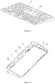
FIG. 1 is a structural schematic diagram of the utility model;
FIG. 2 is an exploded view shown in FIG. 1;
FIG. 3 is a structural schematic diagram of the key locking plate shown in FIG. 2;
FIG. 4 is a structural schematic diagram of the flexible sheet shown in FIG. 2;
FIG. 5 is a structural schematic diagram of the key body shown in FIG. 2;
FIG. 6 is an oblique view shown in FIG. 5;
FIG. 7 is a structural schematic diagram of the upper surface of the PCB board shown in FIG. 2;
FIG. 8 is a structural schematic diagram of the lower surface of the PCB board shown in FIG. 2;
FIG. 9 is a structural schematic diagram of the flexible base shown in FIG. 2;
FIG. 10 is a structural schematic diagram of the fixing frame shown in FIG. 2;
FIG. 11 is a structural schematic diagram of the bottom cap shown in FIG. 2;
In the Figures: 1. Fixed frame; 2. Long flexible strip; 3. Key locking plate; 4. Flexible sheet; 5. PCB board; 6. Flexible base; 7. Bottom cap; 8. Flexible block; 9. Battery; 10. Key body; 11. Upper key hole; 12. Lower key hole; 13. Cross-shaped joint; 14. Guide rod; 15. Touch rod; 16. Guide hole; 17. Through hole; 18. Contact switch; 19. Battery slot; 20. Baffle; 21. Fixing slot; 22. Champing bulge; 23. Clamping groove; 24. Limited post.
EMBODIMENTS
The present utility model will be described in greater detail below based on the Figures and embodiments in order to enable those skilled in the art to better understand the technical solution of present utility model. It should be noted that the embodiments of the present application and the features in the embodiments could be combined with each other given the absence of a conflict.
In the description of the present utility model, it should be understood that the directional or positional relationships indicated by the terms “center”, “longitudinal”, “horizontal”, “length”, “width”, “thickness”, “upper surface”, “lower surface”, “front”, “behind”, “left” and “right”, “vertical”, “horizontal”, “top”, “bottom”, “inner”, “outer”, “clockwise rotation”, “reverse rotation”, “radial direction”, “circumferential direction”, etc. are the directional or positional relationships based on the Figures. The terms are only used to easily describe the present utility model and simplify the description rather than indicate or imply that the relevant device or component must be directionally fixed or constructed and operated in a specific direction. Therefore, they cannot be understood as a limitation on the present utility model.
FIGS. 1, 2, 3, and 4 show a keyboard, which comprises keys, a fixed frame 1, a long flexible strip 2, a key locking plate 3, a flexible sheet 4, a PCB board 5, a flexible base 6 and a bottom cap 7. The key locking plate 3 is mounted on the upper surface of the flexible sheet 4. The flexible sheet 4 is mounted on the upper surface of the PCB board 5. The PCB board 5 is mounted on the flexible base 6. The flexible base 6 is mounted on the bottom cap 7. The fixing frame 1 is connected with the bottom cap 7, forming the housing of the keyboard. The key locking plate 3, the flexible sheet 4, the PCB board 5 and the flexible base 6 are fixed in the housing. The long flexible strip 2 is mounted on all sides of the key locking plate 3 and in the fixing frame 1. The key locking plate 3 and the flexible sheet 4 are respectively provided with an upper key hole 11 and a lower key hole 12.
As shown in FIGS. 5, 6, 7, and 8, a key comprises a key body 10 and a key cap. The key 10 passes through the upper key hole 11 and a lower key hole 12 in turn. To be specific, the cross-shaped joint 13 is provided on the upper end of the key body 10, and the key body 10 is connected with the key cap through the cross-shaped joint 13; the three guide rods 14 and two touch rods 15 are provided on the lower end of the key body 10, and the three guide rods 14 are inserted into the three corresponding guide holes on the PCB board; the two touch rods 15 are used to pass through the corresponding through holes 17 on the PCB board to touch the relevant contact switches 18; because a guide road is additionally provided on the key body, the displacement accuracy of the key is ensured; because touch rods are adopted, the stability of key operation is ensured.
As shown in FIG. 9, a battery slot 19 is provided on the flexible base 6, and a battery 9 is arranged in the battery slot 19, and the battery 9 is used to provide power for the PCB board 5.
As shown in FIGS. 10 and 11, the top of the four walls of the fixing frame 1 extends inwardy to a baffle 20; the surface of the baffle 20 is provided with a holddown groove 21, and the long flexible strip 2 is inserted into the holddown groove 21 to effectively prevent the long flexible strips from moving to achieve a good effect of isolation and vibration reduction.
A clamping bulge 22 is provided on the inner side of the four walls of the fixing frame 1, a clamping slot 23 is provided on the outer side of the four walls of the bottom cap 7, the clamping bulge 22 is mounted in the clamping slot 23, and the fixing frame 1 is clamped to the bottom cap 7.
A limited post 24 is provided at each of the four corners of the bottom cap 7, and after the fixing frame 1 is connected with the bottom cap 7, the top of the limited posts 24 presses against the baffle 20 on the fixing frame 1. A flexible block 8 is arranged between the limited post 24 and the baffle 20 to achieve a better effect of vibration and noise reduction.
In addition, those skilled in the art can combine different embodiments or examples described in this specification together or combine the features of the different embodiments or examples together without contradicting each other. Although the embodiments of the present utility model have been shown and described above, it is understandable that the above embodiments are exemplary and shall not be construed as limiting the present utility model. Those skilled in the art may change, modify, replace and transform the above-mentioned embodiments within the scope of the present utility model.

Claims (8)

The invention claimed is:
1. A keyboard, which is characterized in that it comprises keys, a fixing frame, long flexible strips, a key locking plate, a flexible sheet, a PCB board, a flexible base, and a bottom cap; the key locking plate is mounted on the upper surface of the flexible sheet, the flexible sheet is mounted on the upper surface of the PCB board, the PCB board is mounted on the flexible base, the flexible base is mounted on the bottom cap, the fixing frame is connected with the bottom cap, forming the housing of the keyboard, the key locking plate, the flexible sheet, the PCB board and the flexible base are fixed in the housing, and the long flexible strips are mounted on all sides of the key locking plate and in the fixing frame; the key locking plate and the flexible sheet is respectively provided with an upper key hole and a lower key hole; the key passes through the upper key hole and a lower key hole in turn.
2. The keyboard of claim 1, is characterized in that the top of the four walls of the fixing frame extends inwardy to a baffle, the surface of the baffle is provided with a holddown groove, and the long flexible strips are inserted into the holddown groove.
3. The keyboard of claim 2, is characterized in that a clamping bulge is provided on the inner side of the four walls of the fixing frame, a clamping slot is provided on the outer side of the four walls of the bottom cap, the clamping bulge is mounted in the clamping slot, and the fixing frame is clamped to the bottom cap.
4. The keyboard of claim 3, is characterized in that a limited post is provided at each of the four corners of the bottom cap, and after the fixing frame is connected with the bottom cap, the top of the limited posts presses against the baffle on the fixing frame.
5. The keyboard of claim 4, is characterized in that a flexible block is arranged between the limited posts and the baffle.
6. The keyboard of claim 5, is characterized in that a key comprises a key body and a key cap; a cross-shaped joint is provided on the upper end of the key body, which is connected with the key cap through the cross-shaped joint; a guide rod and two touch rods are provided on the lower end of the key body, and the guide rod is inserted into the corresponding guide hole on the PCB board; the two touch rods are used to pass through the corresponding through holes on the PCB board to touch the relevant contact switches.
7. The keyboard of claim 6, is characterized in that three guide rods are provided on the key body, and three guide holes corresponding to the guide rods are provided on the PCB board.
8. The keyboard of claim 7, is characterized in that a battery dot is provided on the flexible base, and a battery is arranged in the battery dot, and the battery is used to provide power for the PCB board.
US17/399,074 2021-06-17 2021-08-11 Keyboard Active US11435834B2 (en)

Applications Claiming Priority (2)

Application Number Priority Date Filing Date Title
CN202121347791.7 2021-06-17
CN202121347791.7U CN215769668U (en) 2021-06-17 2021-06-17 Keyboard

Publications (2)

Publication Number Publication Date
US20210373674A1 US20210373674A1 (en) 2021-12-02
US11435834B2 true US11435834B2 (en) 2022-09-06

Family

ID=78706175

Family Applications (1)

Application Number Title Priority Date Filing Date
US17/399,074 Active US11435834B2 (en) 2021-06-17 2021-08-11 Keyboard

Country Status (2)

Country Link
US (1) US11435834B2 (en)
CN (1) CN215769668U (en)

Families Citing this family (5)

* Cited by examiner, † Cited by third party
Publication number Priority date Publication date Assignee Title
USD1017605S1 (en) * 2021-09-10 2024-03-12 Logitech Europe S.A. Keyboard
USD997168S1 (en) * 2021-12-09 2023-08-29 Shenzhen Yinchen Technology Co., Ltd Keyboard
USD997169S1 (en) * 2021-12-09 2023-08-29 Shenzhen Yinchen Technology Co., Ltd Keyboard
WO2024073339A2 (en) * 2022-09-27 2024-04-04 Voyetra Turtle Beach, Inc. Keyboard with buffer and silent functions
US20240282536A1 (en) * 2023-02-20 2024-08-22 Glorious Llc Keyboard Gasket Mount System

Citations (8)

* Cited by examiner, † Cited by third party
Publication number Priority date Publication date Assignee Title
US6764191B2 (en) * 2001-06-05 2004-07-20 Matsushita Electric Industrial Co., Ltd. Illumination type keyboard
US7504596B2 (en) * 2007-06-18 2009-03-17 Zippy Technology Corp. Keyboard
US9360948B2 (en) * 2012-03-06 2016-06-07 Gifty Group Ltd Keyboard system with changeable key displays
US10013075B2 (en) * 1999-09-15 2018-07-03 Michael Shipman Illuminated keyboard
US20190091946A1 (en) * 2017-09-25 2019-03-28 Apple Inc. Continuous carbon fiber winding for thin structural ribs
US20200076432A1 (en) * 2018-08-31 2020-03-05 Chicony Electronics Co., Ltd. Keyboard
US20200113040A1 (en) 2018-10-04 2020-04-09 Chicony Electronics Co., Ltd. Keyboard
US20200328049A1 (en) 2019-04-11 2020-10-15 Chicony Electronics Co., Ltd. Keyboard

Patent Citations (8)

* Cited by examiner, † Cited by third party
Publication number Priority date Publication date Assignee Title
US10013075B2 (en) * 1999-09-15 2018-07-03 Michael Shipman Illuminated keyboard
US6764191B2 (en) * 2001-06-05 2004-07-20 Matsushita Electric Industrial Co., Ltd. Illumination type keyboard
US7504596B2 (en) * 2007-06-18 2009-03-17 Zippy Technology Corp. Keyboard
US9360948B2 (en) * 2012-03-06 2016-06-07 Gifty Group Ltd Keyboard system with changeable key displays
US20190091946A1 (en) * 2017-09-25 2019-03-28 Apple Inc. Continuous carbon fiber winding for thin structural ribs
US20200076432A1 (en) * 2018-08-31 2020-03-05 Chicony Electronics Co., Ltd. Keyboard
US20200113040A1 (en) 2018-10-04 2020-04-09 Chicony Electronics Co., Ltd. Keyboard
US20200328049A1 (en) 2019-04-11 2020-10-15 Chicony Electronics Co., Ltd. Keyboard

Also Published As

Publication number Publication date
CN215769668U (en) 2022-02-08
US20210373674A1 (en) 2021-12-02

Similar Documents

Publication Publication Date Title
US11435834B2 (en) Keyboard
CN201374273Y (en) Compound keystroke
CN204117903U (en) A kind of keyboard
CN201387573Y (en) Assistant positioning template of main board stud
CN213938491U (en) Side key FPC location structure and mobile terminal of mobile terminal
CN210199834U (en) Fingerprint lock panel and fingerprint lock cover plate fixing device
CN210630014U (en) Shell structure for fixing double-sided screen
CN203774138U (en) Key structure
CN219228140U (en) Control cabinet easy to overhaul
CN218959191U (en) Blind hole circuit board for Mini-Led display
CN212873386U (en) Computer heat dissipation machine case
CN218004692U (en) Plastic panel on mechanical keyboard
CN219314285U (en) Integrated control box for elevator car
CN214427861U (en) Display screen keyboard and electronic equipment
CN221631945U (en) Touch pad capable of being pressed by five points of keys and keyboard
CN202167392U (en) Low noise keystroke and keyboard employing same
CN211149343U (en) General type computer case
JPH10146944A (en) Printing plate manufacturing apparatus for braille
CN210202186U (en) Mobile phone chip connecting device
CN220986008U (en) Metal plate shell structure of collector of Internet of things
CN218038962U (en) A button amortization structure for pressing return
CN216250494U (en) Integrated metal key
CN219900101U (en) Upper and lower beam pillar structure of punch press
CN219243202U (en) Damping rocker arm support with good stability
CN220651867U (en) CAN bus control switch

Legal Events

Date Code Title Description
FEPP Fee payment procedure

Free format text: ENTITY STATUS SET TO UNDISCOUNTED (ORIGINAL EVENT CODE: BIG.); ENTITY STATUS OF PATENT OWNER: MICROENTITY

FEPP Fee payment procedure

Free format text: ENTITY STATUS SET TO MICRO (ORIGINAL EVENT CODE: MICR); ENTITY STATUS OF PATENT OWNER: MICROENTITY

STPP Information on status: patent application and granting procedure in general

Free format text: DOCKETED NEW CASE - READY FOR EXAMINATION

STPP Information on status: patent application and granting procedure in general

Free format text: NOTICE OF ALLOWANCE MAILED -- APPLICATION RECEIVED IN OFFICE OF PUBLICATIONS

STPP Information on status: patent application and granting procedure in general

Free format text: AWAITING TC RESP., ISSUE FEE NOT PAID

STPP Information on status: patent application and granting procedure in general

Free format text: NOTICE OF ALLOWANCE MAILED -- APPLICATION RECEIVED IN OFFICE OF PUBLICATIONS

STPP Information on status: patent application and granting procedure in general

Free format text: PUBLICATIONS -- ISSUE FEE PAYMENT VERIFIED

STCF Information on status: patent grant

Free format text: PATENTED CASE