US11435686B2 - Detection of waste toner using toner amount detection sensor and switch - Google Patents
Detection of waste toner using toner amount detection sensor and switch Download PDFInfo
- Publication number
- US11435686B2 US11435686B2 US17/413,742 US202017413742A US11435686B2 US 11435686 B2 US11435686 B2 US 11435686B2 US 202017413742 A US202017413742 A US 202017413742A US 11435686 B2 US11435686 B2 US 11435686B2
- Authority
- US
- United States
- Prior art keywords
- waste toner
- toner container
- switch
- main body
- image forming
- Prior art date
- Legal status (The legal status is an assumption and is not a legal conclusion. Google has not performed a legal analysis and makes no representation as to the accuracy of the status listed.)
- Active
Links
- 239000002699 waste material Substances 0.000 title claims abstract description 261
- 238000001514 detection method Methods 0.000 title claims abstract description 83
- 238000007639 printing Methods 0.000 claims abstract description 18
- 230000003287 optical effect Effects 0.000 claims description 35
- 230000001678 irradiating effect Effects 0.000 claims 1
- 230000006870 function Effects 0.000 description 18
- 238000010586 diagram Methods 0.000 description 17
- 238000004891 communication Methods 0.000 description 11
- 238000000034 method Methods 0.000 description 8
- 238000004140 cleaning Methods 0.000 description 6
- 238000003860 storage Methods 0.000 description 3
- 230000005540 biological transmission Effects 0.000 description 2
- 239000003795 chemical substances by application Substances 0.000 description 2
- 230000015572 biosynthetic process Effects 0.000 description 1
- 238000010017 direct printing Methods 0.000 description 1
- 238000003384 imaging method Methods 0.000 description 1
- 239000004973 liquid crystal related substance Substances 0.000 description 1
- 238000004519 manufacturing process Methods 0.000 description 1
- 230000002093 peripheral effect Effects 0.000 description 1
Images


Classifications
-
- G—PHYSICS
- G01—MEASURING; TESTING
- G01F—MEASURING VOLUME, VOLUME FLOW, MASS FLOW OR LIQUID LEVEL; METERING BY VOLUME
- G01F23/00—Indicating or measuring liquid level or level of fluent solid material, e.g. indicating in terms of volume or indicating by means of an alarm
- G01F23/0007—Indicating or measuring liquid level or level of fluent solid material, e.g. indicating in terms of volume or indicating by means of an alarm for discrete indicating and measuring
-
- G—PHYSICS
- G03—PHOTOGRAPHY; CINEMATOGRAPHY; ANALOGOUS TECHNIQUES USING WAVES OTHER THAN OPTICAL WAVES; ELECTROGRAPHY; HOLOGRAPHY
- G03G—ELECTROGRAPHY; ELECTROPHOTOGRAPHY; MAGNETOGRAPHY
- G03G15/00—Apparatus for electrographic processes using a charge pattern
- G03G15/55—Self-diagnostics; Malfunction or lifetime display
- G03G15/553—Monitoring or warning means for exhaustion or lifetime end of consumables, e.g. indication of insufficient copy sheet quantity for a job
- G03G15/556—Monitoring or warning means for exhaustion or lifetime end of consumables, e.g. indication of insufficient copy sheet quantity for a job for toner consumption, e.g. pixel counting, toner coverage detection or toner density measurement
-
- G—PHYSICS
- G01—MEASURING; TESTING
- G01F—MEASURING VOLUME, VOLUME FLOW, MASS FLOW OR LIQUID LEVEL; METERING BY VOLUME
- G01F23/00—Indicating or measuring liquid level or level of fluent solid material, e.g. indicating in terms of volume or indicating by means of an alarm
- G01F23/22—Indicating or measuring liquid level or level of fluent solid material, e.g. indicating in terms of volume or indicating by means of an alarm by measuring physical variables, other than linear dimensions, pressure or weight, dependent on the level to be measured, e.g. by difference of heat transfer of steam or water
- G01F23/28—Indicating or measuring liquid level or level of fluent solid material, e.g. indicating in terms of volume or indicating by means of an alarm by measuring physical variables, other than linear dimensions, pressure or weight, dependent on the level to be measured, e.g. by difference of heat transfer of steam or water by measuring the variations of parameters of electromagnetic or acoustic waves applied directly to the liquid or fluent solid material
- G01F23/284—Electromagnetic waves
- G01F23/292—Light, e.g. infrared or ultraviolet
- G01F23/2921—Light, e.g. infrared or ultraviolet for discrete levels
-
- G—PHYSICS
- G03—PHOTOGRAPHY; CINEMATOGRAPHY; ANALOGOUS TECHNIQUES USING WAVES OTHER THAN OPTICAL WAVES; ELECTROGRAPHY; HOLOGRAPHY
- G03G—ELECTROGRAPHY; ELECTROPHOTOGRAPHY; MAGNETOGRAPHY
- G03G15/00—Apparatus for electrographic processes using a charge pattern
- G03G15/80—Details relating to power supplies, circuits boards, electrical connections
-
- G—PHYSICS
- G03—PHOTOGRAPHY; CINEMATOGRAPHY; ANALOGOUS TECHNIQUES USING WAVES OTHER THAN OPTICAL WAVES; ELECTROGRAPHY; HOLOGRAPHY
- G03G—ELECTROGRAPHY; ELECTROPHOTOGRAPHY; MAGNETOGRAPHY
- G03G21/00—Arrangements not provided for by groups G03G13/00 - G03G19/00, e.g. cleaning, elimination of residual charge
- G03G21/10—Collecting or recycling waste developer
- G03G21/105—Arrangements for conveying toner waste
-
- G—PHYSICS
- G03—PHOTOGRAPHY; CINEMATOGRAPHY; ANALOGOUS TECHNIQUES USING WAVES OTHER THAN OPTICAL WAVES; ELECTROGRAPHY; HOLOGRAPHY
- G03G—ELECTROGRAPHY; ELECTROPHOTOGRAPHY; MAGNETOGRAPHY
- G03G21/00—Arrangements not provided for by groups G03G13/00 - G03G19/00, e.g. cleaning, elimination of residual charge
- G03G21/10—Collecting or recycling waste developer
- G03G21/12—Toner waste containers
-
- G—PHYSICS
- G03—PHOTOGRAPHY; CINEMATOGRAPHY; ANALOGOUS TECHNIQUES USING WAVES OTHER THAN OPTICAL WAVES; ELECTROGRAPHY; HOLOGRAPHY
- G03G—ELECTROGRAPHY; ELECTROPHOTOGRAPHY; MAGNETOGRAPHY
- G03G2215/00—Apparatus for electrophotographic processes
- G03G2215/00362—Apparatus for electrophotographic processes relating to the copy medium handling
- G03G2215/00535—Stable handling of copy medium
- G03G2215/00611—Detector details, e.g. optical detector
- G03G2215/00624—Magnetic detector or switch, e.g. reed switch
Definitions
- An image forming apparatus is an apparatus for generating, printing, receiving and transmitting image data.
- Some examples of the apparatus include a printer, a copy machine, a facsimile, and a multifunction peripheral (MFP) that integrally implements these functions.
- MFP multifunction peripheral
- An image forming apparatus may be operated with one of an inkjet system, a dot-jet system, a laser printer system, and the like according to the printing method of the image forming apparatus.
- the laser printer system may be operated with a method in which a toner is attached to a photosensitive drum on which an electrostatic latent image is formed to convert the electrostatic latent image into a visible toner image, and the toner image is transferred onto paper.
- FIG. 1 is a block diagram schematically illustrating a configuration of an example image forming apparatus
- FIG. 2 is a block diagram schematically illustrating a configuration of an example image forming apparatus
- FIG. 3 is a schematic diagram of an example print engine in the image forming apparatus of FIG. 1 ;
- FIG. 4 is a schematic diagram of a body of an example image forming apparatus and a mountable waste toner container
- FIG. 5 is a schematic diagram of an example arrangement of a toner amount detection sensor and a switch in an image forming apparatus
- FIG. 6 is a schematic diagram of an example toner amount detection sensor type and an example switch
- FIG. 7 is a circuit diagram of an example detection circuit
- FIG. 8 is a circuit diagram of an example detection circuit
- FIG. 9 is a circuit diagram of an example detection circuit
- FIG. 10 is a circuit diagram of an example detection circuit
- FIG. 11 is a flowchart of an example method for detecting an amount of waste toner and detecting a waste toner container.
- a case in which any component is “connected” with another component may refer to a case in which any component is ‘directly connected’ to another component and a case in which a component is ‘connected to another component via yet another component interposed therebetween.
- a case in which any component “comprises” another component may indicate that a component may comprise additional components, without excluding other components, unless it is explicitly described as the contrary.
- image forming job may refer to various jobs or operations related with imaging, such as, formation of image or generation/storage/transmission of image files (e.g., printing, scanning or faxing), and the expression “job” as used herein may refer to an image forming job, or to a series of processes carried out for performance of the image forming job.
- an “image forming apparatus” may refer to a device for printing print data generated from a terminal such as a computer on a recording paper.
- Examples of the image forming apparatus described above may include a copier, a printer, a facsimile, a multi-function printer (MFP) that complexly implement functions thereof through a single device, and the like.
- MFP multi-function printer
- printing data may refer to data converted into a format that may be printed by a printer.
- the printing data may be comprised of a data file or image file.
- the expression “user” may refer to a person who performs one or more manipulation related with the image forming job using the image forming apparatus or a device connected to the image forming apparatus via wire communication or wirelessly.
- FIG. 1 is a block diagram illustrating an example image forming apparatus.
- an example image forming apparatus 100 may include a processor 110 , a print engine 120 , a waste toner container 200 , and a detection circuit 300 .
- the print engine 120 may form an image using a toner.
- the print engine 120 may form an image on a printing medium (or paper) using a photosensitive drum. An example configuration and operation of the print engine 120 will be described with reference to FIG. 3 .
- the waste toner container 200 may collect the waste toner generated by the print engine 120 .
- the waste toner container 200 may have a container shape that contains a waste toner, and collect the waste toner discharged from a cleaning member 129 of the print engine 120 shown in FIG. 3 .
- the waste toner container 200 may be a replaceable consumable product.
- a print job may not be available (e.g., the apparatus may be prevented from proceeding to a printing operation). Therefore, whether the waste toner container 200 is mounted or not and/or the amount of waste toner (or toner amount) in the waste toner container 200 need to be confirmed or determined.
- the detection circuit 300 is used to output a voltage value associated with the amount of waste toner in the waste toner container 200 .
- the detection circuit 300 outputs 0 V or the voltage of a power supply terminal (Vcc) when the waste toner container 200 is not mounted.
- Vcc power supply terminal
- the processor 110 may control the elements of the image forming apparatus 100 .
- the processor 110 may determine whether the waste toner container 200 is mounted, and whether the amount of waste toner in the waste toner container 200 is to be detected. For example, in the occurrence of an event such as when the image forming apparatus 100 is initially driven, when an output job for printing more than a predetermined number of pages is performed, or when the cover of the image forming apparatus 100 is opened or closed, the processor 110 may determine or detect whether the waste toner container 200 is mounted or not as well as the amount of waste toner contained in the waste toner container 200 .
- the processor 110 may control the detection circuit 300 to perform a detection operation.
- the processor 110 may control the detection circuit 300 so that a driving power is applied to a toner amount detection sensor 310 to detect the waste toner amount.
- the processor 110 may determine whether printing is available (e.g., whether to operate the image forming apparatus to print) based on the voltage value output from the detection circuit 300 .
- the processor 110 may be equipped with an Analog Digital Converter (ADC) port for receiving the voltage value, and determine whether the waste toner container 200 is mounted (or whether it is detached or removed from the image forming apparatus 100 ) and the waste toner amount of the waste toner container 200 based on the voltage value detected at the ADC port.
- ADC Analog Digital Converter
- the processor 110 may determine that a print job is not available, and may change an operation state of the image forming apparatus 100 to an error state.
- the processor 110 may determine that the print job is not available, and change the operation state of the image forming apparatus 100 to the error state.
- the error state may be associated with a state of the image forming apparatus 100 , in which a print job is not available due to an operational issue in the image forming apparatus.
- the processor 110 may determine that the waste toner container 200 is to be replaced, and change the operation state of the image forming apparatus 100 to a warning state.
- a predetermined value e.g., a first setting value, or first threshold, less than a second setting value
- the warning state may be associated with an operation mode in which a print job is available, but a manager or a user is informed of a replacement of the waste toner container 200 , or it is displayed that the waste toner container 200 is to be replaced via a display 150 shown in FIG. 2 .
- the processor 110 may determine that the print job is available.
- FIG. 2 is a block diagram illustrating an example image forming apparatus 100 .
- the example image forming apparatus 100 may include a processor 110 , a print engine 120 , a communication device 130 , a memory 140 , a display 150 , an operation input unit (or operation input device) 160 , a waste toner container 200 and a detection circuit 300 .
- the print engine 120 , the waste toner container 200 and the detection circuit 300 may perform similar functions as the corresponding elements described with reference to FIG. 1 , and redundant description thereof will be omitted.
- An operation of the processor 110 has been described with reference to FIG. 1 , and redundant description thereof will be omitted.
- the communication device 130 may be connected to a print control terminal device, to receive print data from the print control terminal device.
- the communication device 130 may connect the image forming apparatus 100 to an external device, and be connected to a terminal device through a local area network (LAN) and the Internet network as well as Universal Serial Bus (USB) port or a wireless communication (e.g., Wi-Fi 802.11a/b/g/n, Near Field Communication (NFC), and Bluetooth) port.
- LAN local area network
- USB Universal Serial Bus
- wireless communication e.g., Wi-Fi 802.11a/b/g/n, Near Field Communication (NFC), and Bluetooth
- Such communication device 130 may also be referred to as a transceiver.
- the communication device 130 may notify a managing server or a manager (e.g., the manager of the terminal device) that the waste toner container 200 is to be replaced.
- a managing server or a manager e.g., the manager of the terminal device
- the memory 140 may store print data received through the communication device 130 .
- the memory 140 may store information on the detected waste toner amount.
- the memory 140 may include a storage medium in the image forming apparatus 100 or an external storage medium, for example, a removable disk such as a USB memory, a web server via network, etc.
- the display 150 may display various information provided by the image forming apparatus 100 .
- the display 150 may display a user interface window for selecting various functions provided by the image forming apparatus 100 .
- the display 150 may include a monitor such as an Liquid Crystal Display (LCD), a Cathode-Ray Tube (CRT), or an Organic Light-Emitting Diode (OLED), or a touch screen capable of simultaneously performing functions of the operation input unit or device 160 , as will be described below.
- LCD Liquid Crystal Display
- CRT Cathode-Ray Tube
- OLED Organic Light-Emitting Diode
- the display 150 may display a control menu for performing the function of the image forming apparatus 100 .
- the display 150 may display information on a consumable product. When it is determined that the waste toner container 200 is to be replaced, the display 150 may display replacement information. The display 150 may display information on a replacement prediction time point.
- the display 150 may display error information. For example, when a print job is not available because the waste toner container 200 is not mounted, and the waste toner is full in the waste toner container 200 , the display 150 may display that the print job is not available.
- the operation input device 160 may receive a function selection and a control command for the function from a user.
- Examples of the function may include a print function, a copy function, a scan function, a fax transmission function, etc.
- the function control command may be received through a control menu displayed on the display 150 .
- the operation input device 160 may include a plurality of buttons, a keyboard, a mouse, etc. or a touch screen that simultaneously perform the function of the display 150 .
- the processor 110 may control the print engine 120 to print the received print data.
- the print control terminal device may be an electronic apparatus for providing print data such as a personal computer (PC), a laptop, a tablet PC, a smart phone, a server, and the like.
- the processor 110 may predict the lifespan of the waste toner container 200 based on information on a change of the waste toner amount, stored in the memory 140 . When the predicted life span reaches at a predetermined time point, the processor 110 may control the display 150 to display an expected lifespan, or control the communication device 130 to notify a user of the expected lifespan.
- the processor 110 may control the display 150 to display that the waste toner container 200 is to be replaced.
- the processor 110 may control the display 150 to display that the waste toner container 200 is to be replaced.
- the processor 110 may control the communication device 130 to notify a user that the print job is not available.
- the processor 110 may identify whether the waste toner container 200 is mounted, and the amount of waste toner in the waste toner container 200 .
- the operation mode of the image forming apparatus 100 may be changed from the warning mode or the error mode to the normal mode.
- the image forming apparatus 100 may reduce manufacturing or operational costs by identifying whether the waste toner container 200 is mounted and the amount of waste toner in the waste toner container 200 by using a single sensor.
- the processor 110 may be designed without much limitation because whether the waste toner container 200 is mounted and the amount of waste toner can be identified by using a single port, thereby reducing complexities in the implementation of the processor 110 .
- the waste toner container 200 and the print engine 120 have been separately described.
- the waste toner container 200 may be included in the print engine 120 .
- the detection circuit 300 may be included in the print engine 120 .
- FIG. 3 is a view to explain an example of a detailed configuration of the print engine of FIG. 1 .
- the print engine 120 may include a photosensitive drum 121 , a charger 122 , an exposure device 123 , a transfer device 125 , a developer 126 , a fuser 128 , and a cleaning member 129 .
- the electrostatic latent image may be formed on the photosensitive drum 121 .
- the photosensitive drum 121 may be replaced with a photosensitive belt, or another suitable form depending on examples.
- the charger 122 may charge the surface of the photosensitive drum 121 to a uniform potential.
- the charger 122 may be implemented in the form of a corona charger, a charging roller, a charging brush, or the like.
- the exposure device 123 may form an electrostatic latent image on the surface of the photosensitive drum 121 by changing a surface potential of the photosensitive drum 121 according to image information to be printed.
- the developer 126 may include a developer agent therein and develop the electrostatic latent image into a visible image.
- the developer 126 may include a developing roller 127 which supplies the developer agent to the electrostatic latent image.
- the developer 126 may be contained in a toner cartridge that is replaceable.
- the visible image formed onto the photosensitive drum 121 may be transferred to a printing medium P by the transfer device 125 or an intermediate transfer belt (ITB).
- ITB intermediate transfer belt
- the fuser 128 may fix the visible image to the printing medium P by applying heat and pressure to the visible image on the printing medium P. Through a series of processes, a print job may be completed.
- the cleaning member 129 may remove the remaining toner that is not transferred to the printing medium P of the image forming on the photosensitive drum 121 , and discharge the remaining toner to be removed to the waste toner container 200 .
- the waste toner container 200 When the waste toner container 200 is filled with waste toner, the waste toner may be replaced by a new waste toner container 200 .
- the waste toner container 200 may be referred to as a consumable product because the waste toner container 200 can be replaced.
- the cleaning member 129 and the waste toner container 200 are illustrated separately, but at the time of implementation, all or part of the cleaning member 129 may be combined with the waste toner container 200 .
- FIG. 4 is a view illustrating an example of a mounting type of a waste toner container 200 .
- a body (or main body) 101 of the image forming apparatus 100 may include an area (e.g., a mounting area) in which the waste toner container 200 is mounted.
- the waste toner container 200 may be mounted at the mounting area, and when the waste toner container 200 is mounted on the body 101 , referring to FIG. 3 , waste toner discharged from the cleaning member 129 may be collected therein.
- the waste toner container 200 may include an optical member 210 and a protrusion member 220 on a surface that contacts the body 101 .
- the optical member 210 may transmit light from the outside to the inside of the waste toner container 200 .
- the optical member 210 may be provided as a single member or a plurality of optical members.
- the optical member 210 may include a lens, and when provided as a plurality of optical members, the optical member 210 may include a plurality of optical waveguides. A description thereof will be made with reference to FIG. 5 .
- the protrusion member 220 may be shaped to protrude from a surface of the waste toner container 200 and operate a switch 320 even when the waste toner container 200 is spaced away from the body 101 .
- the switch 320 may be operated through contact with a contact surface of the waste toner container 200 , and the protrusion member 220 may be omitted.
- the detection circuit 300 may include the switch 320 for detecting the mounting of the waste toner container 200 as well as the toner amount detection sensor 310 for detecting the amount of waste toner in the waste toner container 200 .
- the toner amount detection sensor 310 may be disposed on a side of the body 101 facing the optical member 210 of the waste toner container 200 .
- the toner amount detection sensor 310 may output a voltage value associated with the amount of waste toner in the waste toner container 200 .
- An example configuration and circuit of the toner amount detection sensor 310 will be described with reference to FIG. 5 to FIG. 10 .
- the switch 320 may be disposed on a surface of the body 101 where the waste toner container 200 is to be mounted, and the electrical connection state of the switch 320 may vary depending on whether the waste toner container 200 is mounted or not. In some examples, when the waste toner container 200 is mounted, both ends of the switch 320 may be shorted (e.g., the ends of the switch 320 may be connected to conduct current to the circuit in the body 101 ), and when the waste toner container 200 is detached, both ends of the switch 320 may be opened so as to disconnect the circuit of the switch 320 and interrupt the flow of electric current. In other examples, when the waste toner container 200 is mounted, both ends of the switch 320 may be opened, and when the waste toner container 200 is detached, both ends of the switch 320 is shorted.
- the switch 320 may be electrically located between the toner amount detection sensor 310 and the processor 110 to selectively output the output value of the toner amount detection sensor 310 to the processor 110 , depending on whether or not the waste toner container 200 is mounted onto the body 101 .
- the switch 320 may be an interlock switch, or may include a plurality of terminals and a conductive member.
- An example interlock switch will be described with reference to FIG. 5 .
- An example where the switch 320 includes a plurality of terminals and a conductive member will be described with reference to FIG. 6 .
- FIG. 4 schematically illustrates the body 101 to include the toner amount detection sensor 310 and the switch 320 .
- a locking member that is physically fixed to the waste toner container 200 may be added to the body 101 or the waste toner container 200 .
- FIG. 5 is a schematic diagram illustrating an example arrangement of a toner amount detection sensor 310 and a switch 320 .
- the waste toner container 200 may include an optical member 210 .
- the optical member 210 may include optical waveguides 211 and 213 .
- the first optical waveguide 211 may be an optical waveguide for transmitting light irradiated from an external source into an inside of the waste toner container 200 .
- the external source e.g., a light emitter 311
- the irradiated light may be transmitted into the inside of the waste toner container 200 through the first optical waveguide 211 .
- the light transmitted into the inside may be reflected in the waste toner container 200 , and part of the reflective light may be incident on the second optical waveguide 213 .
- the second optical waveguide 213 may be an optical waveguide extending from a first end located inside the waste toner container 200 to a second end located at an outer surface (or outside) of the waste toner container 200 , to transmit light reflected in the waste toner container 200 to the outside. Accordingly, the light incident on the first end on inside of the second optical waveguide 213 may be transmitted to the second end on outside of the second optical waveguide 213 .
- the second optical waveguide 213 may output no light or very little light.
- the toner amount detection sensor 310 may include a light emitter 311 and a light receiver 313 to be disposed adjacent to each other, and positioned to align with the optical waveguides 211 and 213 of the waste toner container 200 . Accordingly, the circuit design in the image forming apparatus 100 may be simplified because the light emitter 311 and the light receiver 313 are mounted to be adjacent to each other.
- the light emitter 311 may irradiate light.
- the light emitter 311 may be disposed to be opposite to the end of the outside of the first optical waveguide 211 , and when a driving power is applied, the light emitter 311 may irradiate light toward the first optical waveguide 211 .
- the light irradiated from the light emitter 311 may be transmitted to the inside of the waste toner container 200 through the first optical waveguide 211 , and part of the reflective light may be output to the outside through the second optical waveguide 213 .
- the light receiver 313 may detect light, and output a voltage value associated with the detected light.
- the light receiver 313 may be positioned to face the second end of the second optical waveguide 213 at the outer surface of the waste toner container 200 , and may output a voltage value corresponding to a light intensity (or light amount) output from the second optical waveguide 213 .
- the light receiver may include a Negative-Positive-Negative (NPN) type light receiver (hereinafter referred to as NPN light receiver) that outputs a voltage value in proportion to the intensity of light.
- NPN light receiver may include a Positive-Negative-Positive (PNP) type light receiver (hereinafter referred to as PNP light receiver) that outputs a voltage value inversely proportional to the intensity of light.
- NPN light receiver 314 will be described with reference to FIG. 7 and FIG. 8 .
- An example PNP light receiver 315 will be described with reference to FIG. 9 and FIG. 10 .
- the switch 320 may be located to face the protrusion member 220 of the waste toner container 200 , and the electrical connection state of the switch 320 may be either shorted or opened depending on whether the waste toner container 200 is mounted. At the time of implementation, an interlock switch may be used as the switch 320 .
- the interlock switch may include a first type that is shorted in the presence of pressure, and opened in the absence of pressure.
- the interlock switch may include a second type that is opened in the presence of pressure (when pressed), and shorted (e.g., closed) in the absence of pressure (when not pressed).
- the protrusion member 220 of the waste toner container 200 may allow contact with the body 101 , when the waste toner container 200 is mounted with a distance between the waste toner container 200 and the body 101 .
- the protrusion member 220 of the waste toner container 200 may be located at a position on the waste toner container 200 to face the interlock switch.
- the protrusion member 220 may be provided when the image forming apparatus 100 is designed to mount the waste toner container 200 to the body 101 with a space or distance between the waste toner container 200 and the body 101 .
- the protrusion member 220 could be omitted for example, when a lack of contact resulting from the distance does not occur.
- FIG. 6 The elements illustrated in FIG. 6 are similar to those illustrated in FIG. 5 , however a conductive member 240 is further disposed on the surface of the protrusion member 220 of a waste toner container 200 ′. Elements illustrated in FIG. 6 , that differ from those illustrated in FIG. 5 will be described.
- a toner amount detection sensor 310 ′ may include a light emitter 311 , a light receiver 313 and a guide member 319 disposed to be adjacent to one another.
- the light emitter 311 and the light receiver 313 may perform similar functions as those of FIG. 5 .
- the guide member 319 may guide light irradiated from the light emitter 311 in a forward direction. Accordingly, light irradiated from the light emitter 311 may be prevented from being directly transmitted to the light receiver 313 .
- An example switch 320 ′ may comprise two terminals 329 and the conductive member 240 .
- the two terminals 329 may be spaced apart on the body 101 .
- the two terminals 329 may correspond to the ends of the switch 320 ′.
- the conductive member 240 may be formed on the protrusion member 220 , so as to electrically connect the two terminals 329 on the side of the body 101 when the waste toner container 200 ′ is mounted onto the body 101 .
- the switch 320 ′ according to the second example may be opened in a state in which the waste toner container 200 ′ is not mounted, and may be shorted by the conductive member 240 of the waste toner container 200 ′ when the waste toner container 200 ′ is mounted.
- the guide member 319 is disposed in the vicinity of the light emitter 311 .
- the function of the guide member 319 is to prevent the light of the light emitter 311 from being directly irradiated to the light receiver 313 .
- the guide member 319 may be disposed in the vicinity of the light receiver 313 , or disposed between the light emitter 311 and the light receiver 313 .
- FIG. 4 to FIG. 6 illustrate examples where the switch includes an interlock switch or a plurality of terminals and a conductive member, and in the example, when the waste toner container is mounted, the switch may be shorted or opened. Additionally, when the waste toner container is detached, the switch may be electrically opened or shorted). Other configurations of the switch may be used in other examples.
- FIG. 7 is a circuit diagram illustrating an example detection circuit 300 that includes a pull-up circuit 330 , and an NPN light receiver 314 .
- the detection circuit 300 may include a toner amount detection sensor 310 , a switch 321 , the pull-up circuit 330 , and a driving circuit 350 .
- the toner amount detection sensor 310 may comprise the light emitter 311 and the NPN light receiver 314 .
- the light emitter 311 may irradiate light when a driving power is received from the driving circuit 350 .
- One end of the light emitter 311 may be connected to a power supply terminal through a resistance, and the other end may be connected to one end of the driving circuit 350 (e.g., a cathode of a transistor).
- the light emitter 311 may include a Light-Emitting Diode (LED).
- NPN light receiver 314 One end of the NPN light receiver 314 may be connected to the switch 321 , and the other end of the NPN light receiver 314 may be grounded. Since the NPN light receiver 314 is an NPN light receiver, the NPN light receiver 314 may be turned on when light is sensed, and when light is not sensed, may be turned off to output a voltage value corresponding to a light intensity.
- the switch 321 may be shorted when the waste toner container 200 is mounted, and may be opened when the waste toner container 200 is detached. One end of the switch 321 may be connected to the pull-up circuit 330 , and the other end of the switch 321 may be connected to the NPN light receiver 314 .
- the switch 321 may be an interlock switch, and in other examples, the switch 321 may include two terminals and a conductive member with reference to FIG. 6 .
- the pull-up circuit 330 may comprise two resistances and may be a circuit that outputs a voltage of the power supply terminal Vcc to the output terminal in a floating state (e.g., in a state in which the waste toner container 200 is not amounted).
- One end of the pull-up circuit 330 may be connected to an ADC port of the processor 110 , and another end of the pull-up circuit 330 may be connected to the switch 321 .
- the driving circuit 350 may provide a driving power to the light emitter 311 according to a control signal of the processor 110 .
- the switch 321 of the detection circuit 300 may be turned off (e.g., to interrupt the conductive path), and the power of the power supply terminal Vcc may be provided to the ADC port of the processor 110 .
- the detection circuit 300 may output a voltage that corresponds to the power supply terminal Vcc.
- the switch 321 When the waste toner container 200 is connected (e.g. mounted on the body 101 ), the switch 321 may be turned on to close the conducting path, and the detection circuit 300 may output a voltage value associated with the waste toner amount, wherein the voltage value may be within a voltage range from 0V to a voltage lower than the voltage of the power supply terminal by a predetermined voltage value.
- the processor 110 may determine that the waste toner container 200 is not mounted.
- the processor 110 may calculate the amount of waste toner associated with the input voltage value. As the amount of waste toner in the waste toner container 200 increases, the voltage value of the NPN light receiver 314 decrease. Accordingly, in some examples, the output voltage value of the detection circuit 300 may be inversely proportional to the amount of waste toner.
- FIG. 8 is a circuit diagram of another example detection circuit 300 ′ that includes a pull-down circuit 340 , and an NPN light receiver 314 ′.
- the detection circuit 300 ′ may include a toner amount detection sensor 310 ′, a switch 321 ′, a pull-down circuit 340 , and the driving circuit 350 .
- the operations of the light emitter 311 and the driving circuit 350 are similar to those described with reference to FIG. 7 .
- One end of the NPN light receiver 314 ′ may be connected to the switch 321 ′, and the other end may be connected to the power supply terminal Vcc.
- the switch 321 ′ may be shorted (e.g., closed) when the waste toner container 200 is mounted on the body 101 , and opened when the waste toner container 200 is detached.
- One end of the switch 321 ′ may be connected to the pull down circuit 340 , and the other end may be connected to the NPN light receiver 314 ′.
- the switch 321 ′ may include an interlock switch, and in other examples, the switch 321 ′ may include the two terminals and the conductive member described with reference to FIG. 6 .
- the pull-down circuit 340 comprising two resistances may output 0V voltage to the output terminal in a floating state (e.g., in a state in which the waste toner container 200 is not mounted).
- One end of the pull down circuit 340 may be connected to the ADC port of the processor 110 , and another end may be connected to the switch 321 ′.
- the switch 321 ′ of the detection circuit 300 ′ may be turned off, and thus the ADC port of the processor 110 may be connected to the ground.
- the detection circuit 300 ′ may output a voltage of 0V when the waste toner container 200 is not connected.
- the switch 321 ′ When the waste toner container 200 is connected, the switch 321 ′ may be turned on, the detection circuit 300 ′ may output a voltage value associated with the amount of waste toner, within a voltage range from a voltage slightly higher than 0V to the voltage of the power supply terminal Vcc.
- the processor 110 may determine that the waste toner container 200 is not mounted.
- the processor 110 may calculate the amount of waste toner associated with the input voltage value. As the amount of waste toner increases in the waste toner container 200 , the voltage value of the NPN light receiver 314 ′ may decrease. Accordingly, in some examples, the output voltage value of the detection circuit 300 ′ may be inversely proportional to the amount of waste toner.
- FIG. 9 is a circuit diagram of another example detection circuit 300 ′′ that includes a pull up circuit 330 , and the PNP light receiver 315 .
- the detection circuit 300 ′′ may comprise a toner amount detection sensor 310 ′′, a switch 325 , the pull-up circuit 330 , and the driving circuit 350 .
- the operations of the light emitter 311 and the driving circuit 350 are similar to those of FIG. 7 .
- One end of the PNP light receiver 315 may be connected to both the switch 325 and the pull-up circuit 330 , and the other end may be grounded.
- the switch 325 may be opened when the waste toner container 200 is mounted, and the switch 325 may be closed when the waste toner container 200 is detached.
- One end of the switch 325 may be connected to both the pull-up circuit 330 , and the PNP light receiver 315 , and the other end of the switch 325 may be grounded.
- the switch 325 may be an interlock switch.
- the pull-up circuit 330 comprising two resistances may output a voltage of 0V to the output terminal in a floating state (e.g., in a state where the waste toner container 200 is not mounted).
- One end of the pull-up circuit 330 may be connected to the ADC port of the processor 110 , and the other end may be connected to the switch 325 and to the PNP light receiver 315 .
- the switch 325 of the detection circuit 300 ′′ may be turned on (e.g., closed), and thus the ADC port of the processor 110 may be connected to the ground. Accordingly, when the waste toner container 200 is not connected, the detection circuit 300 ′′ may output the voltage of 0V.
- the switch 325 When the waste toner container 200 is connected, the switch 325 may be turned off (opened), and thus the detection circuit 300 ′′ may output a voltage value associated with the amount of waste toner from a voltage slightly higher than 0V to the voltage of the power supply terminal Vcc.
- the processor 110 may determine that the waste toner container 200 is not mounted.
- the amount of waste toner associated with the input voltage value may be calculated.
- the voltage value of the PNP light receiver 315 may increase. Accordingly, in some examples, the output voltage value of the detection circuit 300 ′′ may be proportional to the amount of waste toner.
- FIG. 10 is a circuit diagram of an example detection circuit 300 ′′′ that includes a pull-down circuit 340 and a PNP light receiver 315 ′.
- the detection circuit 300 ′′′ may include a toner amount detection sensor 310 ′′′, a switch 325 ′, the pull-down circuit 340 , and the driving circuit 350 .
- the operations of the light emitter 311 and the driving circuit 350 are similar to the operations of FIG. 7 .
- One end of the PNP light receiver 315 ′ may be connected to the switch 325 ′ and to the pull down circuit 340 , and the other end may be connected to a power supply terminal.
- the switch 325 ′ may be opened when the waste toner container 200 is mounted, and the switch 325 ′ may be shorted (e.g., closed) when the waste toner container 200 is detached.
- One end of the switch 325 ′ may be connected to the pull-down circuit 340 and to the PNP light receiver 315 ′, and the other end may be connected to the power supply terminal.
- the switch 325 ′ may be an interlock switch.
- the pull-down circuit 340 comprising two resistances may be a circuit that outputs the voltage of the power supply terminal to the output terminal in a floating state (e.g., in a state in which a waste toner container 200 is not mounted).
- One end of the pull down circuit 340 may be connected to the ADC port of the processor 110 , and the other end of the pull-down circuit 340 may be connected to the switch 325 ′ and to the PNP light receiver 315 ′.
- the switch 325 ′ of the detection circuit 300 ′ may be turned on, and thus the ADC port of the processor 110 may be connected to the power supply terminal.
- the detection circuit 300 ′ may output the same voltage as the power supply terminal Vcc.
- the switch 325 ′ When the waste toner container 200 is connected, the switch 325 ′ may be turned off, and a voltage value associated with the amount of waste toner may be output, within a voltage range from 0V to a voltage that is less than the voltage of the power supply terminal by a predetermined voltage value.
- the processor 110 may determine that the waste toner container 200 is not mounted.
- the processor 110 may calculate the amount of waste toner associated with the input voltage value. As the amount of waste toner in the waste toner container 200 increases, the voltage value of the PNP light receiver 315 ′ increases. For example, the output voltage value of the detection circuit 300 ′′′ may be proportional to the amount of waste toner.
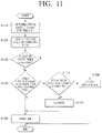
- FIG. 11 is a flowchart illustrating an example method for detecting an amount of waste toner and detecting a presence of a waste toner container on the body.
- a driving power may be supplied to the light emitter at operation S 1110 .
- the output voltage value of the driving circuit may be sensed through the ADC port at operation S 1120 .
- Whether the waste toner container is mounted or not may be sensed based on the sensing value at operation S 1130 . For example, when a pull-up circuit and an NPN light receiver are used, or when a pull-down circuit and a PNP light receiver are used, the waste toner container may be determined as being detached when the sensed voltage value is Vcc. When the sensed voltage value is equal to or less than Vcc, the waste toner container may be determined as being mounted.
- the waste toner container may be detected as being detached. If the sensed voltage is equal to or more than the voltage value of 0V, the waste toner container may be determined as being mounted.
- the waste toner container When the waste toner container is mounted, it may be determined whether the sensed voltage value is equal to or more than a first setting value (e.g., a first threshold value) at operation S 1140 , where the first setting value may be associated with a warning value.
- a first setting value e.g., a first threshold value
- a print job may be performed in a normal mode at operation SS 160 .
- the sensed voltage value is greater than the first setting value, it may be determined whether the value is equal to or more than the second setting value, which may indicate that the waste toner is full in the waste toner container, at operation S 1150 .
- the operation mode of the image forming apparatus may be changed to a warning mode at operation S 1170 .
- a print job may also be performed in the warning mode.
- the operation mode of the image forming apparatus may be changed to an error mode at operation S 1180 .
- the image forming apparatus may be prevented from performing the print job.
- the method for detecting the amount of waste toner and a waste toner container may reduce costs because a single sensor detects the mounting of the waste toner container and the amount of waste toner in the waste toner container, and enable a system design with reduced limitations (e.g., with minimal complexity) because the processor detects the mounting of the waste toner container and the amount of waste toner by using a single port.
- the above-described sensing method may be implemented by a program, in the form of processor-readable data and instructions stored on one or more memory device, and provided to an image forming apparatus.
- the data and instructions of the program containing a sensing or detection method may be stored and provided in a non-transitory computer readable medium.
Landscapes
- Physics & Mathematics (AREA)
- General Physics & Mathematics (AREA)
- Life Sciences & Earth Sciences (AREA)
- Engineering & Computer Science (AREA)
- Environmental & Geological Engineering (AREA)
- Sustainable Development (AREA)
- Electromagnetism (AREA)
- Fluid Mechanics (AREA)
- Thermal Sciences (AREA)
- Cleaning In Electrography (AREA)
- Control Or Security For Electrophotography (AREA)
Abstract
Description
Claims (20)
Applications Claiming Priority (3)
| Application Number | Priority Date | Filing Date | Title |
|---|---|---|---|
| KR10-2019-0072301 | 2019-06-18 | ||
| KR1020190072301A KR20200144354A (en) | 2019-06-18 | 2019-06-18 | Detection of waster toner using switch |
| PCT/US2020/033389 WO2020256871A1 (en) | 2019-06-18 | 2020-05-18 | Detection of waste toner using switch |
Publications (2)
| Publication Number | Publication Date |
|---|---|
| US20220100137A1 US20220100137A1 (en) | 2022-03-31 |
| US11435686B2 true US11435686B2 (en) | 2022-09-06 |
Family
ID=74036986
Family Applications (1)
| Application Number | Title | Priority Date | Filing Date |
|---|---|---|---|
| US17/413,742 Active US11435686B2 (en) | 2019-06-18 | 2020-05-18 | Detection of waste toner using toner amount detection sensor and switch |
Country Status (3)
| Country | Link |
|---|---|
| US (1) | US11435686B2 (en) |
| KR (1) | KR20200144354A (en) |
| WO (1) | WO2020256871A1 (en) |
Citations (9)
| Publication number | Priority date | Publication date | Assignee | Title |
|---|---|---|---|---|
| JP2003345203A (en) | 2002-05-23 | 2003-12-03 | Panasonic Communications Co Ltd | Waste toner detection device and electrophotographic recording means |
| US7356269B2 (en) * | 2002-12-30 | 2008-04-08 | Samsung Electronics Co., Ltd. | Apparatus and method for sensing waste toner in an electrophotographic image forming apparatus |
| JP2008216445A (en) | 2007-03-01 | 2008-09-18 | Canon Inc | Image forming apparatus |
| US20090066749A1 (en) | 2007-09-06 | 2009-03-12 | Young Paul D | Collecting waste ink in a printer system |
| US20100080600A1 (en) | 2008-09-29 | 2010-04-01 | Ricoh Company, Ltd. | Collection container, cleaning unit, and image forming apparatus capable of collecting waste toner efficiently |
| JP2012058284A (en) | 2010-09-03 | 2012-03-22 | Ricoh Co Ltd | Waste image forming material detecting device and image forming apparatus |
| US8204390B2 (en) | 2008-12-26 | 2012-06-19 | Kyocera Mita Corporation | Image forming apparatus and method for detecting the fullness of waste-toner container |
| JP2013037204A (en) | 2011-08-09 | 2013-02-21 | Konica Minolta Business Technologies Inc | Image forming apparatus |
| JP2016206593A (en) | 2015-04-28 | 2016-12-08 | キヤノンファインテック株式会社 | Toner quantity detecting device, and image formation apparatus |
-
2019
- 2019-06-18 KR KR1020190072301A patent/KR20200144354A/en not_active Withdrawn
-
2020
- 2020-05-18 US US17/413,742 patent/US11435686B2/en active Active
- 2020-05-18 WO PCT/US2020/033389 patent/WO2020256871A1/en not_active Ceased
Patent Citations (9)
| Publication number | Priority date | Publication date | Assignee | Title |
|---|---|---|---|---|
| JP2003345203A (en) | 2002-05-23 | 2003-12-03 | Panasonic Communications Co Ltd | Waste toner detection device and electrophotographic recording means |
| US7356269B2 (en) * | 2002-12-30 | 2008-04-08 | Samsung Electronics Co., Ltd. | Apparatus and method for sensing waste toner in an electrophotographic image forming apparatus |
| JP2008216445A (en) | 2007-03-01 | 2008-09-18 | Canon Inc | Image forming apparatus |
| US20090066749A1 (en) | 2007-09-06 | 2009-03-12 | Young Paul D | Collecting waste ink in a printer system |
| US20100080600A1 (en) | 2008-09-29 | 2010-04-01 | Ricoh Company, Ltd. | Collection container, cleaning unit, and image forming apparatus capable of collecting waste toner efficiently |
| US8204390B2 (en) | 2008-12-26 | 2012-06-19 | Kyocera Mita Corporation | Image forming apparatus and method for detecting the fullness of waste-toner container |
| JP2012058284A (en) | 2010-09-03 | 2012-03-22 | Ricoh Co Ltd | Waste image forming material detecting device and image forming apparatus |
| JP2013037204A (en) | 2011-08-09 | 2013-02-21 | Konica Minolta Business Technologies Inc | Image forming apparatus |
| JP2016206593A (en) | 2015-04-28 | 2016-12-08 | キヤノンファインテック株式会社 | Toner quantity detecting device, and image formation apparatus |
Also Published As
| Publication number | Publication date |
|---|---|
| US20220100137A1 (en) | 2022-03-31 |
| KR20200144354A (en) | 2020-12-29 |
| WO2020256871A1 (en) | 2020-12-24 |
Similar Documents
| Publication | Publication Date | Title |
|---|---|---|
| US8873976B2 (en) | Image forming apparatus, system and method | |
| JP5384577B2 (en) | Printing control apparatus, printing apparatus, printing control method, and printing control system | |
| US20090225348A1 (en) | Image forming apparatus giving notification of error in apparatus to develop user and service person's awareness | |
| JP7413798B2 (en) | Image forming apparatus, image forming system, control method and program for image forming apparatus | |
| US20130089343A1 (en) | Image forming apparatus and method thereof | |
| JP7413799B2 (en) | Image forming apparatus, image forming system, control method and program for image forming apparatus | |
| JP5812745B2 (en) | Print control apparatus, print control method, and print control system | |
| US20070065166A1 (en) | Image forming apparatus and waste toner warning method | |
| US11435686B2 (en) | Detection of waste toner using toner amount detection sensor and switch | |
| US10317815B2 (en) | Image forming apparatus, method for managing consumable, and storage medium | |
| JP6059767B2 (en) | Print control apparatus and print control method | |
| JP5766069B2 (en) | Print control apparatus, print control method, and print control system | |
| US10892685B2 (en) | Power supply device and image forming apparatus having the same | |
| US11635922B2 (en) | Image recording device | |
| US10645251B2 (en) | Image scanning apparatus and method of controlling scan | |
| JP7463889B2 (en) | Terminal device and program | |
| JP6159765B2 (en) | Print control apparatus, print control method, and print control system | |
| US11930144B2 (en) | Energy-saving information processing apparatus, image forming apparatus, and method for controlling energy-saving information processing apparatus | |
| JP7447511B2 (en) | Image forming device and image forming system | |
| JP2015119347A (en) | Electrical equipment | |
| JP5450367B2 (en) | Image forming apparatus | |
| JP5833881B2 (en) | Image forming apparatus, method, system, and printer driver | |
| JP2017203866A (en) | Image forming apparatus and replacement parts |
Legal Events
| Date | Code | Title | Description |
|---|---|---|---|
| AS | Assignment |
Owner name: HEWLETT-PACKARD DEVELOPMENT COMPANY, L.P., TEXAS Free format text: CONFIRMATORY PATENT ASSIGNMENT;ASSIGNOR:HP PRINTING KOREA CO., LTD.;REEL/FRAME:056587/0846 Effective date: 20210218 Owner name: HP PRINTING KOREA CO., LTD., KOREA, REPUBLIC OF Free format text: ASSIGNMENT OF ASSIGNORS INTEREST;ASSIGNORS:KIM, DANG YOU;IM, JUN BIN;HAN, JAE HEE;REEL/FRAME:056587/0785 Effective date: 20191211 Owner name: HEWLETT-PACKARD DEVELOPMENT COMPANY, L.P., TEXAS Free format text: ASSIGNMENT OF ASSIGNORS INTEREST;ASSIGNOR:HP PRINTING KOREA CO., LTD.;REEL/FRAME:056533/0383 Effective date: 20210507 |
|
| FEPP | Fee payment procedure |
Free format text: ENTITY STATUS SET TO UNDISCOUNTED (ORIGINAL EVENT CODE: BIG.); ENTITY STATUS OF PATENT OWNER: LARGE ENTITY |
|
| STPP | Information on status: patent application and granting procedure in general |
Free format text: NON FINAL ACTION MAILED |
|
| STPP | Information on status: patent application and granting procedure in general |
Free format text: NOTICE OF ALLOWANCE MAILED -- APPLICATION RECEIVED IN OFFICE OF PUBLICATIONS |
|
| STPP | Information on status: patent application and granting procedure in general |
Free format text: PUBLICATIONS -- ISSUE FEE PAYMENT VERIFIED |
|
| STCF | Information on status: patent grant |
Free format text: PATENTED CASE |