US11427171B2 - Vehicle and method of controlling the same - Google Patents
Vehicle and method of controlling the same Download PDFInfo
- Publication number
- US11427171B2 US11427171B2 US17/103,547 US202017103547A US11427171B2 US 11427171 B2 US11427171 B2 US 11427171B2 US 202017103547 A US202017103547 A US 202017103547A US 11427171 B2 US11427171 B2 US 11427171B2
- Authority
- US
- United States
- Prior art keywords
- vehicle
- obstacle
- collision
- controller
- map information
- Prior art date
- Legal status (The legal status is an assumption and is not a legal conclusion. Google has not performed a legal analysis and makes no representation as to the accuracy of the status listed.)
- Active
Links
- 238000000034 method Methods 0.000 title claims description 18
- 230000004044 response Effects 0.000 claims abstract description 9
- 238000005259 measurement Methods 0.000 claims description 21
- 238000010586 diagram Methods 0.000 description 14
- 238000001514 detection method Methods 0.000 description 6
- 238000005516 engineering process Methods 0.000 description 4
- 230000002401 inhibitory effect Effects 0.000 description 3
- 239000013598 vector Substances 0.000 description 3
- 238000007792 addition Methods 0.000 description 2
- 230000008859 change Effects 0.000 description 2
- 230000003111 delayed effect Effects 0.000 description 2
- 238000012986 modification Methods 0.000 description 2
- 230000004048 modification Effects 0.000 description 2
- 230000008569 process Effects 0.000 description 2
- 230000003213 activating effect Effects 0.000 description 1
- 230000008901 benefit Effects 0.000 description 1
- 238000004891 communication Methods 0.000 description 1
- 230000000295 complement effect Effects 0.000 description 1
- 238000012937 correction Methods 0.000 description 1
- 238000013500 data storage Methods 0.000 description 1
- 210000003195 fascia Anatomy 0.000 description 1
- 238000012423 maintenance Methods 0.000 description 1
- 239000011159 matrix material Substances 0.000 description 1
- 229910044991 metal oxide Inorganic materials 0.000 description 1
- 150000004706 metal oxides Chemical class 0.000 description 1
- 230000003287 optical effect Effects 0.000 description 1
- 238000012545 processing Methods 0.000 description 1
- 239000004065 semiconductor Substances 0.000 description 1
- 230000035945 sensitivity Effects 0.000 description 1
- 238000006467 substitution reaction Methods 0.000 description 1
- 230000000007 visual effect Effects 0.000 description 1
Images


Classifications
-
- B—PERFORMING OPERATIONS; TRANSPORTING
- B60—VEHICLES IN GENERAL
- B60W—CONJOINT CONTROL OF VEHICLE SUB-UNITS OF DIFFERENT TYPE OR DIFFERENT FUNCTION; CONTROL SYSTEMS SPECIALLY ADAPTED FOR HYBRID VEHICLES; ROAD VEHICLE DRIVE CONTROL SYSTEMS FOR PURPOSES NOT RELATED TO THE CONTROL OF A PARTICULAR SUB-UNIT
- B60W60/00—Drive control systems specially adapted for autonomous road vehicles
- B60W60/001—Planning or execution of driving tasks
- B60W60/0015—Planning or execution of driving tasks specially adapted for safety
- B60W60/0016—Planning or execution of driving tasks specially adapted for safety of the vehicle or its occupants
-
- B—PERFORMING OPERATIONS; TRANSPORTING
- B60—VEHICLES IN GENERAL
- B60W—CONJOINT CONTROL OF VEHICLE SUB-UNITS OF DIFFERENT TYPE OR DIFFERENT FUNCTION; CONTROL SYSTEMS SPECIALLY ADAPTED FOR HYBRID VEHICLES; ROAD VEHICLE DRIVE CONTROL SYSTEMS FOR PURPOSES NOT RELATED TO THE CONTROL OF A PARTICULAR SUB-UNIT
- B60W30/00—Purposes of road vehicle drive control systems not related to the control of a particular sub-unit, e.g. of systems using conjoint control of vehicle sub-units, or advanced driver assistance systems for ensuring comfort, stability and safety or drive control systems for propelling or retarding the vehicle
- B60W30/08—Active safety systems predicting or avoiding probable or impending collision or attempting to minimise its consequences
- B60W30/09—Taking automatic action to avoid collision, e.g. braking and steering
-
- B—PERFORMING OPERATIONS; TRANSPORTING
- B60—VEHICLES IN GENERAL
- B60T—VEHICLE BRAKE CONTROL SYSTEMS OR PARTS THEREOF; BRAKE CONTROL SYSTEMS OR PARTS THEREOF, IN GENERAL; ARRANGEMENT OF BRAKING ELEMENTS ON VEHICLES IN GENERAL; PORTABLE DEVICES FOR PREVENTING UNWANTED MOVEMENT OF VEHICLES; VEHICLE MODIFICATIONS TO FACILITATE COOLING OF BRAKES
- B60T8/00—Arrangements for adjusting wheel-braking force to meet varying vehicular or ground-surface conditions, e.g. limiting or varying distribution of braking force
- B60T8/17—Using electrical or electronic regulation means to control braking
- B60T8/174—Using electrical or electronic regulation means to control braking characterised by using special control logic, e.g. fuzzy logic, neural computing
-
- B—PERFORMING OPERATIONS; TRANSPORTING
- B60—VEHICLES IN GENERAL
- B60W—CONJOINT CONTROL OF VEHICLE SUB-UNITS OF DIFFERENT TYPE OR DIFFERENT FUNCTION; CONTROL SYSTEMS SPECIALLY ADAPTED FOR HYBRID VEHICLES; ROAD VEHICLE DRIVE CONTROL SYSTEMS FOR PURPOSES NOT RELATED TO THE CONTROL OF A PARTICULAR SUB-UNIT
- B60W30/00—Purposes of road vehicle drive control systems not related to the control of a particular sub-unit, e.g. of systems using conjoint control of vehicle sub-units, or advanced driver assistance systems for ensuring comfort, stability and safety or drive control systems for propelling or retarding the vehicle
- B60W30/08—Active safety systems predicting or avoiding probable or impending collision or attempting to minimise its consequences
-
- B—PERFORMING OPERATIONS; TRANSPORTING
- B60—VEHICLES IN GENERAL
- B60R—VEHICLES, VEHICLE FITTINGS, OR VEHICLE PARTS, NOT OTHERWISE PROVIDED FOR
- B60R21/00—Arrangements or fittings on vehicles for protecting or preventing injuries to occupants or pedestrians in case of accidents or other traffic risks
- B60R21/01—Electrical circuits for triggering passive safety arrangements, e.g. airbags, safety belt tighteners, in case of vehicle accidents or impending vehicle accidents
- B60R21/013—Electrical circuits for triggering passive safety arrangements, e.g. airbags, safety belt tighteners, in case of vehicle accidents or impending vehicle accidents including means for detecting collisions, impending collisions or roll-over
- B60R21/0134—Electrical circuits for triggering passive safety arrangements, e.g. airbags, safety belt tighteners, in case of vehicle accidents or impending vehicle accidents including means for detecting collisions, impending collisions or roll-over responsive to imminent contact with an obstacle, e.g. using radar systems
-
- B—PERFORMING OPERATIONS; TRANSPORTING
- B60—VEHICLES IN GENERAL
- B60T—VEHICLE BRAKE CONTROL SYSTEMS OR PARTS THEREOF; BRAKE CONTROL SYSTEMS OR PARTS THEREOF, IN GENERAL; ARRANGEMENT OF BRAKING ELEMENTS ON VEHICLES IN GENERAL; PORTABLE DEVICES FOR PREVENTING UNWANTED MOVEMENT OF VEHICLES; VEHICLE MODIFICATIONS TO FACILITATE COOLING OF BRAKES
- B60T8/00—Arrangements for adjusting wheel-braking force to meet varying vehicular or ground-surface conditions, e.g. limiting or varying distribution of braking force
- B60T8/17—Using electrical or electronic regulation means to control braking
- B60T8/171—Detecting parameters used in the regulation; Measuring values used in the regulation
-
- B—PERFORMING OPERATIONS; TRANSPORTING
- B60—VEHICLES IN GENERAL
- B60W—CONJOINT CONTROL OF VEHICLE SUB-UNITS OF DIFFERENT TYPE OR DIFFERENT FUNCTION; CONTROL SYSTEMS SPECIALLY ADAPTED FOR HYBRID VEHICLES; ROAD VEHICLE DRIVE CONTROL SYSTEMS FOR PURPOSES NOT RELATED TO THE CONTROL OF A PARTICULAR SUB-UNIT
- B60W10/00—Conjoint control of vehicle sub-units of different type or different function
- B60W10/18—Conjoint control of vehicle sub-units of different type or different function including control of braking systems
- B60W10/184—Conjoint control of vehicle sub-units of different type or different function including control of braking systems with wheel brakes
-
- B—PERFORMING OPERATIONS; TRANSPORTING
- B60—VEHICLES IN GENERAL
- B60W—CONJOINT CONTROL OF VEHICLE SUB-UNITS OF DIFFERENT TYPE OR DIFFERENT FUNCTION; CONTROL SYSTEMS SPECIALLY ADAPTED FOR HYBRID VEHICLES; ROAD VEHICLE DRIVE CONTROL SYSTEMS FOR PURPOSES NOT RELATED TO THE CONTROL OF A PARTICULAR SUB-UNIT
- B60W30/00—Purposes of road vehicle drive control systems not related to the control of a particular sub-unit, e.g. of systems using conjoint control of vehicle sub-units, or advanced driver assistance systems for ensuring comfort, stability and safety or drive control systems for propelling or retarding the vehicle
- B60W30/08—Active safety systems predicting or avoiding probable or impending collision or attempting to minimise its consequences
- B60W30/095—Predicting travel path or likelihood of collision
- B60W30/0956—Predicting travel path or likelihood of collision the prediction being responsive to traffic or environmental parameters
-
- B—PERFORMING OPERATIONS; TRANSPORTING
- B60—VEHICLES IN GENERAL
- B60W—CONJOINT CONTROL OF VEHICLE SUB-UNITS OF DIFFERENT TYPE OR DIFFERENT FUNCTION; CONTROL SYSTEMS SPECIALLY ADAPTED FOR HYBRID VEHICLES; ROAD VEHICLE DRIVE CONTROL SYSTEMS FOR PURPOSES NOT RELATED TO THE CONTROL OF A PARTICULAR SUB-UNIT
- B60W30/00—Purposes of road vehicle drive control systems not related to the control of a particular sub-unit, e.g. of systems using conjoint control of vehicle sub-units, or advanced driver assistance systems for ensuring comfort, stability and safety or drive control systems for propelling or retarding the vehicle
- B60W30/18—Propelling the vehicle
- B60W30/18009—Propelling the vehicle related to particular drive situations
- B60W30/181—Preparing for stopping
-
- B—PERFORMING OPERATIONS; TRANSPORTING
- B60—VEHICLES IN GENERAL
- B60W—CONJOINT CONTROL OF VEHICLE SUB-UNITS OF DIFFERENT TYPE OR DIFFERENT FUNCTION; CONTROL SYSTEMS SPECIALLY ADAPTED FOR HYBRID VEHICLES; ROAD VEHICLE DRIVE CONTROL SYSTEMS FOR PURPOSES NOT RELATED TO THE CONTROL OF A PARTICULAR SUB-UNIT
- B60W40/00—Estimation or calculation of non-directly measurable driving parameters for road vehicle drive control systems not related to the control of a particular sub unit, e.g. by using mathematical models
- B60W40/02—Estimation or calculation of non-directly measurable driving parameters for road vehicle drive control systems not related to the control of a particular sub unit, e.g. by using mathematical models related to ambient conditions
-
- B—PERFORMING OPERATIONS; TRANSPORTING
- B60—VEHICLES IN GENERAL
- B60W—CONJOINT CONTROL OF VEHICLE SUB-UNITS OF DIFFERENT TYPE OR DIFFERENT FUNCTION; CONTROL SYSTEMS SPECIALLY ADAPTED FOR HYBRID VEHICLES; ROAD VEHICLE DRIVE CONTROL SYSTEMS FOR PURPOSES NOT RELATED TO THE CONTROL OF A PARTICULAR SUB-UNIT
- B60W40/00—Estimation or calculation of non-directly measurable driving parameters for road vehicle drive control systems not related to the control of a particular sub unit, e.g. by using mathematical models
- B60W40/10—Estimation or calculation of non-directly measurable driving parameters for road vehicle drive control systems not related to the control of a particular sub unit, e.g. by using mathematical models related to vehicle motion
- B60W40/105—Speed
-
- B—PERFORMING OPERATIONS; TRANSPORTING
- B60—VEHICLES IN GENERAL
- B60W—CONJOINT CONTROL OF VEHICLE SUB-UNITS OF DIFFERENT TYPE OR DIFFERENT FUNCTION; CONTROL SYSTEMS SPECIALLY ADAPTED FOR HYBRID VEHICLES; ROAD VEHICLE DRIVE CONTROL SYSTEMS FOR PURPOSES NOT RELATED TO THE CONTROL OF A PARTICULAR SUB-UNIT
- B60W50/00—Details of control systems for road vehicle drive control not related to the control of a particular sub-unit, e.g. process diagnostic or vehicle driver interfaces
- B60W50/08—Interaction between the driver and the control system
- B60W50/14—Means for informing the driver, warning the driver or prompting a driver intervention
-
- B—PERFORMING OPERATIONS; TRANSPORTING
- B60—VEHICLES IN GENERAL
- B60W—CONJOINT CONTROL OF VEHICLE SUB-UNITS OF DIFFERENT TYPE OR DIFFERENT FUNCTION; CONTROL SYSTEMS SPECIALLY ADAPTED FOR HYBRID VEHICLES; ROAD VEHICLE DRIVE CONTROL SYSTEMS FOR PURPOSES NOT RELATED TO THE CONTROL OF A PARTICULAR SUB-UNIT
- B60W60/00—Drive control systems specially adapted for autonomous road vehicles
- B60W60/001—Planning or execution of driving tasks
- B60W60/0011—Planning or execution of driving tasks involving control alternatives for a single driving scenario, e.g. planning several paths to avoid obstacles
-
- G—PHYSICS
- G01—MEASURING; TESTING
- G01C—MEASURING DISTANCES, LEVELS OR BEARINGS; SURVEYING; NAVIGATION; GYROSCOPIC INSTRUMENTS; PHOTOGRAMMETRY OR VIDEOGRAMMETRY
- G01C21/00—Navigation; Navigational instruments not provided for in groups G01C1/00 - G01C19/00
- G01C21/38—Electronic maps specially adapted for navigation; Updating thereof
- G01C21/3804—Creation or updating of map data
- G01C21/3807—Creation or updating of map data characterised by the type of data
- G01C21/3815—Road data
-
- G—PHYSICS
- G06—COMPUTING; CALCULATING OR COUNTING
- G06V—IMAGE OR VIDEO RECOGNITION OR UNDERSTANDING
- G06V20/00—Scenes; Scene-specific elements
- G06V20/50—Context or environment of the image
- G06V20/56—Context or environment of the image exterior to a vehicle by using sensors mounted on the vehicle
- G06V20/58—Recognition of moving objects or obstacles, e.g. vehicles or pedestrians; Recognition of traffic objects, e.g. traffic signs, traffic lights or roads
- G06V20/586—Recognition of moving objects or obstacles, e.g. vehicles or pedestrians; Recognition of traffic objects, e.g. traffic signs, traffic lights or roads of parking space
-
- G—PHYSICS
- G08—SIGNALLING
- G08G—TRAFFIC CONTROL SYSTEMS
- G08G1/00—Traffic control systems for road vehicles
- G08G1/16—Anti-collision systems
- G08G1/168—Driving aids for parking, e.g. acoustic or visual feedback on parking space
-
- B—PERFORMING OPERATIONS; TRANSPORTING
- B60—VEHICLES IN GENERAL
- B60T—VEHICLE BRAKE CONTROL SYSTEMS OR PARTS THEREOF; BRAKE CONTROL SYSTEMS OR PARTS THEREOF, IN GENERAL; ARRANGEMENT OF BRAKING ELEMENTS ON VEHICLES IN GENERAL; PORTABLE DEVICES FOR PREVENTING UNWANTED MOVEMENT OF VEHICLES; VEHICLE MODIFICATIONS TO FACILITATE COOLING OF BRAKES
- B60T2201/00—Particular use of vehicle brake systems; Special systems using also the brakes; Special software modules within the brake system controller
- B60T2201/02—Active or adaptive cruise control system; Distance control
- B60T2201/022—Collision avoidance systems
-
- B—PERFORMING OPERATIONS; TRANSPORTING
- B60—VEHICLES IN GENERAL
- B60T—VEHICLE BRAKE CONTROL SYSTEMS OR PARTS THEREOF; BRAKE CONTROL SYSTEMS OR PARTS THEREOF, IN GENERAL; ARRANGEMENT OF BRAKING ELEMENTS ON VEHICLES IN GENERAL; PORTABLE DEVICES FOR PREVENTING UNWANTED MOVEMENT OF VEHICLES; VEHICLE MODIFICATIONS TO FACILITATE COOLING OF BRAKES
- B60T2210/00—Detection or estimation of road or environment conditions; Detection or estimation of road shapes
- B60T2210/30—Environment conditions or position therewithin
- B60T2210/32—Vehicle surroundings
-
- B—PERFORMING OPERATIONS; TRANSPORTING
- B60—VEHICLES IN GENERAL
- B60W—CONJOINT CONTROL OF VEHICLE SUB-UNITS OF DIFFERENT TYPE OR DIFFERENT FUNCTION; CONTROL SYSTEMS SPECIALLY ADAPTED FOR HYBRID VEHICLES; ROAD VEHICLE DRIVE CONTROL SYSTEMS FOR PURPOSES NOT RELATED TO THE CONTROL OF A PARTICULAR SUB-UNIT
- B60W50/00—Details of control systems for road vehicle drive control not related to the control of a particular sub-unit, e.g. process diagnostic or vehicle driver interfaces
- B60W2050/0001—Details of the control system
- B60W2050/0002—Automatic control, details of type of controller or control system architecture
- B60W2050/0004—In digital systems, e.g. discrete-time systems involving sampling
- B60W2050/0005—Processor details or data handling, e.g. memory registers or chip architecture
-
- B—PERFORMING OPERATIONS; TRANSPORTING
- B60—VEHICLES IN GENERAL
- B60W—CONJOINT CONTROL OF VEHICLE SUB-UNITS OF DIFFERENT TYPE OR DIFFERENT FUNCTION; CONTROL SYSTEMS SPECIALLY ADAPTED FOR HYBRID VEHICLES; ROAD VEHICLE DRIVE CONTROL SYSTEMS FOR PURPOSES NOT RELATED TO THE CONTROL OF A PARTICULAR SUB-UNIT
- B60W50/00—Details of control systems for road vehicle drive control not related to the control of a particular sub-unit, e.g. process diagnostic or vehicle driver interfaces
- B60W2050/0001—Details of the control system
- B60W2050/0019—Control system elements or transfer functions
- B60W2050/0022—Gains, weighting coefficients or weighting functions
- B60W2050/0025—Transfer function weighting factor
-
- B—PERFORMING OPERATIONS; TRANSPORTING
- B60—VEHICLES IN GENERAL
- B60W—CONJOINT CONTROL OF VEHICLE SUB-UNITS OF DIFFERENT TYPE OR DIFFERENT FUNCTION; CONTROL SYSTEMS SPECIALLY ADAPTED FOR HYBRID VEHICLES; ROAD VEHICLE DRIVE CONTROL SYSTEMS FOR PURPOSES NOT RELATED TO THE CONTROL OF A PARTICULAR SUB-UNIT
- B60W50/00—Details of control systems for road vehicle drive control not related to the control of a particular sub-unit, e.g. process diagnostic or vehicle driver interfaces
- B60W2050/0001—Details of the control system
- B60W2050/0019—Control system elements or transfer functions
- B60W2050/0026—Lookup tables or parameter maps
-
- B—PERFORMING OPERATIONS; TRANSPORTING
- B60—VEHICLES IN GENERAL
- B60W—CONJOINT CONTROL OF VEHICLE SUB-UNITS OF DIFFERENT TYPE OR DIFFERENT FUNCTION; CONTROL SYSTEMS SPECIALLY ADAPTED FOR HYBRID VEHICLES; ROAD VEHICLE DRIVE CONTROL SYSTEMS FOR PURPOSES NOT RELATED TO THE CONTROL OF A PARTICULAR SUB-UNIT
- B60W50/00—Details of control systems for road vehicle drive control not related to the control of a particular sub-unit, e.g. process diagnostic or vehicle driver interfaces
- B60W50/08—Interaction between the driver and the control system
- B60W50/14—Means for informing the driver, warning the driver or prompting a driver intervention
- B60W2050/143—Alarm means
-
- B—PERFORMING OPERATIONS; TRANSPORTING
- B60—VEHICLES IN GENERAL
- B60W—CONJOINT CONTROL OF VEHICLE SUB-UNITS OF DIFFERENT TYPE OR DIFFERENT FUNCTION; CONTROL SYSTEMS SPECIALLY ADAPTED FOR HYBRID VEHICLES; ROAD VEHICLE DRIVE CONTROL SYSTEMS FOR PURPOSES NOT RELATED TO THE CONTROL OF A PARTICULAR SUB-UNIT
- B60W2420/00—Indexing codes relating to the type of sensors based on the principle of their operation
- B60W2420/40—Photo or light sensitive means, e.g. infrared sensors
- B60W2420/403—Image sensing, e.g. optical camera
-
- B—PERFORMING OPERATIONS; TRANSPORTING
- B60—VEHICLES IN GENERAL
- B60W—CONJOINT CONTROL OF VEHICLE SUB-UNITS OF DIFFERENT TYPE OR DIFFERENT FUNCTION; CONTROL SYSTEMS SPECIALLY ADAPTED FOR HYBRID VEHICLES; ROAD VEHICLE DRIVE CONTROL SYSTEMS FOR PURPOSES NOT RELATED TO THE CONTROL OF A PARTICULAR SUB-UNIT
- B60W2420/00—Indexing codes relating to the type of sensors based on the principle of their operation
- B60W2420/54—Audio sensitive means, e.g. ultrasound
-
- B—PERFORMING OPERATIONS; TRANSPORTING
- B60—VEHICLES IN GENERAL
- B60W—CONJOINT CONTROL OF VEHICLE SUB-UNITS OF DIFFERENT TYPE OR DIFFERENT FUNCTION; CONTROL SYSTEMS SPECIALLY ADAPTED FOR HYBRID VEHICLES; ROAD VEHICLE DRIVE CONTROL SYSTEMS FOR PURPOSES NOT RELATED TO THE CONTROL OF A PARTICULAR SUB-UNIT
- B60W2520/00—Input parameters relating to overall vehicle dynamics
- B60W2520/04—Vehicle stop
-
- B—PERFORMING OPERATIONS; TRANSPORTING
- B60—VEHICLES IN GENERAL
- B60W—CONJOINT CONTROL OF VEHICLE SUB-UNITS OF DIFFERENT TYPE OR DIFFERENT FUNCTION; CONTROL SYSTEMS SPECIALLY ADAPTED FOR HYBRID VEHICLES; ROAD VEHICLE DRIVE CONTROL SYSTEMS FOR PURPOSES NOT RELATED TO THE CONTROL OF A PARTICULAR SUB-UNIT
- B60W2520/00—Input parameters relating to overall vehicle dynamics
- B60W2520/10—Longitudinal speed
-
- B—PERFORMING OPERATIONS; TRANSPORTING
- B60—VEHICLES IN GENERAL
- B60W—CONJOINT CONTROL OF VEHICLE SUB-UNITS OF DIFFERENT TYPE OR DIFFERENT FUNCTION; CONTROL SYSTEMS SPECIALLY ADAPTED FOR HYBRID VEHICLES; ROAD VEHICLE DRIVE CONTROL SYSTEMS FOR PURPOSES NOT RELATED TO THE CONTROL OF A PARTICULAR SUB-UNIT
- B60W2552/00—Input parameters relating to infrastructure
- B60W2552/50—Barriers
-
- B—PERFORMING OPERATIONS; TRANSPORTING
- B60—VEHICLES IN GENERAL
- B60W—CONJOINT CONTROL OF VEHICLE SUB-UNITS OF DIFFERENT TYPE OR DIFFERENT FUNCTION; CONTROL SYSTEMS SPECIALLY ADAPTED FOR HYBRID VEHICLES; ROAD VEHICLE DRIVE CONTROL SYSTEMS FOR PURPOSES NOT RELATED TO THE CONTROL OF A PARTICULAR SUB-UNIT
- B60W2554/00—Input parameters relating to objects
- B60W2554/40—Dynamic objects, e.g. animals, windblown objects
- B60W2554/404—Characteristics
- B60W2554/4049—Relationship among other objects, e.g. converging dynamic objects
-
- B—PERFORMING OPERATIONS; TRANSPORTING
- B60—VEHICLES IN GENERAL
- B60W—CONJOINT CONTROL OF VEHICLE SUB-UNITS OF DIFFERENT TYPE OR DIFFERENT FUNCTION; CONTROL SYSTEMS SPECIALLY ADAPTED FOR HYBRID VEHICLES; ROAD VEHICLE DRIVE CONTROL SYSTEMS FOR PURPOSES NOT RELATED TO THE CONTROL OF A PARTICULAR SUB-UNIT
- B60W2554/00—Input parameters relating to objects
- B60W2554/80—Spatial relation or speed relative to objects
- B60W2554/801—Lateral distance
-
- B—PERFORMING OPERATIONS; TRANSPORTING
- B60—VEHICLES IN GENERAL
- B60W—CONJOINT CONTROL OF VEHICLE SUB-UNITS OF DIFFERENT TYPE OR DIFFERENT FUNCTION; CONTROL SYSTEMS SPECIALLY ADAPTED FOR HYBRID VEHICLES; ROAD VEHICLE DRIVE CONTROL SYSTEMS FOR PURPOSES NOT RELATED TO THE CONTROL OF A PARTICULAR SUB-UNIT
- B60W2554/00—Input parameters relating to objects
- B60W2554/80—Spatial relation or speed relative to objects
- B60W2554/802—Longitudinal distance
-
- B—PERFORMING OPERATIONS; TRANSPORTING
- B60—VEHICLES IN GENERAL
- B60W—CONJOINT CONTROL OF VEHICLE SUB-UNITS OF DIFFERENT TYPE OR DIFFERENT FUNCTION; CONTROL SYSTEMS SPECIALLY ADAPTED FOR HYBRID VEHICLES; ROAD VEHICLE DRIVE CONTROL SYSTEMS FOR PURPOSES NOT RELATED TO THE CONTROL OF A PARTICULAR SUB-UNIT
- B60W2710/00—Output or target parameters relating to a particular sub-units
- B60W2710/18—Braking system
- B60W2710/182—Brake pressure, e.g. of fluid or between pad and disc
-
- B—PERFORMING OPERATIONS; TRANSPORTING
- B60—VEHICLES IN GENERAL
- B60Y—INDEXING SCHEME RELATING TO ASPECTS CROSS-CUTTING VEHICLE TECHNOLOGY
- B60Y2300/00—Purposes or special features of road vehicle drive control systems
- B60Y2300/08—Predicting or avoiding probable or impending collision
-
- B—PERFORMING OPERATIONS; TRANSPORTING
- B60—VEHICLES IN GENERAL
- B60Y—INDEXING SCHEME RELATING TO ASPECTS CROSS-CUTTING VEHICLE TECHNOLOGY
- B60Y2300/00—Purposes or special features of road vehicle drive control systems
- B60Y2300/18—Propelling the vehicle
- B60Y2300/18008—Propelling the vehicle related to particular drive situations
- B60Y2300/18091—Preparing for stopping
-
- B—PERFORMING OPERATIONS; TRANSPORTING
- B60—VEHICLES IN GENERAL
- B60Y—INDEXING SCHEME RELATING TO ASPECTS CROSS-CUTTING VEHICLE TECHNOLOGY
- B60Y2400/00—Special features of vehicle units
- B60Y2400/30—Sensors
- B60Y2400/303—Speed sensors
Definitions
- the present disclosure relates to a vehicle for performing parking collision-avoidance control during parking and a method of controlling the same.
- Autonomous driving technologies for vehicle are designed to automatically drive a vehicle by identifying the condition of a road, without a driver needing to control a brake, a steering wheel, an accelerator pedal, and the like.
- the autonomous driving technology is a key technology for realizing smart cars.
- the technologies include a highway driving assist (HAD) for automatically maintaining the distance between vehicles, a blind spot detection (BSD) for sounding alarm by detecting surrounding vehicles while reversing, an autonomous emergency braking (AEB) for activating a braking system upon failure to recognize a preceding vehicle, a lane departure warning system (LDWS), a lane keeping assistance system (LKAS) for inhibiting a vehicle from departing a lane without lighting a turn signal, a lane maintenance assistance system (LKAS) for avoiding leaving the lane without a turn signal, an advanced smart cruise control (ASCC) for performing travel at a designated speed while maintaining a distance between vehicles, a traffic jam assistant (TJA) system, a parking collision-avoidance assist (PCA), and the like.
- HAD highway driving assist
- BSD blind spot detection
- AEB autonomous emergency braking
- LKAS lane keeping assistance system
- ASCC advanced smart cruise control
- TJA traffic jam assistant
- the present disclosure provides a vehicle capable of inhibiting erroneous braking in a parking collision-avoidance assist (PCA) system by estimating the position of an obstacle using an ultrasonic sensor and a camera provided in the vehicle, and a method of controlling the same.
- PCA parking collision-avoidance assist
- It is an aspect of the disclosure to provide a vehicle including: a sensor part configured to acquire occupancy information of a surrounding area of the vehicle and a speed of the vehicle; a camera configured to acquire a surrounding image of the vehicle; and a controller configured to: form map information based on the occupancy information according to movement of the vehicle; determine presence or absence of an obstacle around the vehicle based on the map information and the surrounding image; and control, in response to the presence of the obstacle, the vehicle based on the presence of the obstacle and a possibility of collision of the vehicle derived from the speed of the vehicle and the map information.
- the controller may form the map information by assigning a first weight to occupancy information of a first area that is measured in real time, and assigning a second weight greater than the first weight to occupancy information of a second area that is previously measured.
- the controller may form the map information by assigning a third weight to the occupancy information corresponding to a third area having no obstacle.
- the controller may classify each pixel included in an image based on the surrounding image into one of a space, a low obstacle, and a normal obstacle.
- the controller may be configured to determine a time to collision between the vehicle and the obstacle, and when the possibility of collision of the vehicle exceeds a predetermined reference value, and the obstacle corresponds to the normal obstacle, stop the vehicle.
- the controller may be configured to, when the possibility of collision of the vehicle exceeds a predetermined reference value, and the obstacle corresponds to the low obstacle, stop the vehicle after a predetermined time since the obstacle is detected.
- the controller may be configured to determine a time to collision between the vehicle and the obstacle, and compare the time to collision with a reference braking time corresponding to the speed of the vehicle to determine a braking timing of the vehicle.
- the controller may determine the occupancy information corresponding to the obstacle and pixels included in the surrounding image, and form the map information based on a covariance of the occupancy information and a covariance of the pixels.
- the vehicle may further include an outputter, wherein the controller may output a warning signal to the outputter based on the possibility of collision of the vehicle.
- the controller may determine the possibility of collision of the vehicle by comparing a reference time corresponding to the speed of the vehicle with a time to collision of the vehicle with the obstacle.
- the vehicle may further include a braking part, wherein the controller may control the braking part based on the possibility of collision of the vehicle.
- the forming of the map information may include: forming the map information by assigning a first weight to occupancy information of a first area that is measured in real time; and assigning a second weight greater than the first weight to occupancy information of a second area that is previously measured.
- the forming of the map information may include forming the map information by assigning a third weight to the occupancy information corresponding to a third area having no obstacle.
- the forming of the map information may include classifying each pixel included in an image based on the surrounding image into one of a space, a low obstacle, and a normal obstacle.
- the controlling of the vehicle may include: determining a time to collision between the vehicle and the obstacle; and when the possibility of collision of the vehicle exceeds a predetermined reference value, and the obstacle corresponds to the normal obstacle, stopping the vehicle.
- the controlling of the vehicle may include: when the possibility of collision of the vehicle exceeds a predetermined reference value, and the obstacle corresponds to the low obstacle, stopping the vehicle after a predetermined time since the obstacle is detected.
- the controlling of the vehicle may include determining a time to collision between the vehicle and the obstacle, and comparing the time to collision with a reference braking time corresponding to the speed of the vehicle to determine a braking timing of the vehicle.
- the forming of the map information may include determining the occupancy information corresponding to the obstacle and pixels included in the surrounding image, and forming the map information based on a covariance of the occupancy information and a covariance of the pixels.
- It is another aspect of the disclosure to provide a vehicle including: an ultrasonic sensor configured to acquire occupancy information of a surrounding area of the vehicle based on an ultrasonic signal; a wheel speed sensor configured to acquire a speed of the vehicle; a camera configured to acquire a surrounding image of the vehicle; and at least one processor configured to: assign an occupation probability corresponding to the occupancy information; by using a time-slice measurement model determined based on the speed of the vehicle, assign a first weight to occupancy information of a first area that is measured in real time, and assign a second weight greater than the first weight to occupancy information of a second area that is previously measured to determine an occupancy probability of the previously measured area, assign a third weight to occupancy information corresponding to a third area to reduce an occupancy probability corresponding to the third area; determine coordinate information corresponding to the surrounding image and the vehicle; determine an obstacle map by classifying each pixel corresponding to the occupancy information into at least one of a space, a low obstacle, and a normal obstacle on the basis of a covariance corresponding to map information
- FIG. 1 is a control block diagram illustrating a vehicle according to one form of the present disclosure
- FIG. 2 is a diagram for describing a side obstacle detection area according to one form of the present disclosure
- FIG. 3 is a diagram for describing a time slice measurement model according to one form of the present disclosure
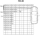
- FIGS. 4A to 4D are diagrams for describing a process of forming map information according to one form of the present disclosure
- FIG. 5 is a diagram for describing an operation of detecting an obstacle based on a surrounding image and map information according to one form of the present disclosure
- FIG. 6 is a diagram for describing braking control according to one form of the present disclosure.
- FIG. 7 is a diagram for describing an operation of outputting a warning signal according to one form of the present disclosure.
- FIG. 8 is a flowchart according to one form of the present disclosure.
- connection or its derivatives refer both to direct and indirect connection, and the indirect connection includes a connection over a wireless communication network.
- first,” “second,” “A,” “B,” etc. may be used to describe various components, the terms do not limit the corresponding components, but are used only for the purpose of distinguishing one component from another component.
- FIG. 1 is a control block diagram illustrating a vehicle 1 according to one form of the present disclosure.
- the vehicle 1 may include a sensor part 100 , a camera 200 , an outputter 400 , a braking part 300 , and a controller 500 .
- the sensor part 100 may include an ultrasonic sensor 110 and a wheel speed sensor 120 .
- the ultrasonic sensor 110 may employ a method of transmitting ultrasonic waves and detecting a distance to an obstacle using ultrasonic waves reflected from the obstacle.
- the sensor part 100 may acquire occupancy information of a surrounding area of the vehicle.
- the occupancy information may refer to information obtained by determining whether a space around the vehicle is occupied by a specific object, such as an obstacle.
- the wheel speed sensor 120 is installed at each of four wheels including front and rear wheels to detect the rotational speed of the wheel by a change in magnetic field lines of a tone wheel and a sensor.
- the camera 200 may acquire a surrounding image of the vehicle.
- the camera 200 may be provided at the front, rear, and sides of the vehicle to acquire an image.
- the camera 200 installed on the vehicle may include a charge-coupled device (CCD) camera or a complementary metal-oxide semiconductor (CMOS) color image sensor.
- CCD charge-coupled device
- CMOS complementary metal-oxide semiconductor
- the CCD and the CMOS may refer to a sensor that converts light received through a lens of the camera into an electric signal.
- the CCD camera refers to an apparatus that converts an image into an electric signal using a charge-coupled device.
- a CMOS image sensor CIS refers to a low-consumption and low-power type image pickup device having a CMOS structure, and serves as an electronic film of a digital device.
- the CCD has a sensitivity superior than that of the CIS and thus is widely used in the vehicle, but the present disclosure is not limited thereto.
- the braking part 300 may control the speed of the vehicle based on a signal from the controller.
- the braking part 300 may include a hydraulic control unit (HCU) that is a hydraulic control device, a sensor that detects the speed of a wheel, a pedal travel switch (PTS) that detects a state of stepping on a brake, a disc brake, and a caliper, but the present disclosure is not limited thereto.
- HCU hydraulic control unit
- PTS pedal travel switch
- the outputter 400 may be configured to output a warning signal based on a possibility of collision.
- the outputter 400 may be configured to include a display or speaker provided in a cluster or center fascia of a vehicle.
- the controller 500 may form map information based on occupancy information according to movement of the vehicle.
- the controller 500 may acquire occupancy information using a time slice measurement model according to movement of the vehicle, and form map information based on the occupancy information. Details thereof will be described below.
- the map information may refer to information formed based on the occupancy information and indicating whether an obstacle exists around the vehicle.
- the controller 500 may determine whether an obstacle exists around the vehicle based on the map information and the surrounding image.
- the controller 500 may determine presence or absence of an obstacle around the vehicle using the occupancy information acquired by the ultrasonic sensor together with the surrounding image acquired by the camera.
- the controller 500 may, in response to the presence of the obstacle, control the braking part 300 based on the presence of the obstacle and the possibility of collision of the vehicle derived based on the speed of the vehicle and the map information.
- the controller 500 may immediately stop the vehicle by operating the braking part when a collision is expected to occur between the vehicle and the obstacle based on the above-described operation.
- the controller may form the map information by assigning a first weight to occupancy information of an area measured in real time, and assigning a second weight greater than the first weight to occupancy information of an area previously measured.
- a previously measured area is determined to have occupancy information with a higher reliability. Accordingly, the occupancy information of the previously measured area is assigned a weight higher than that of the occupancy information acquired in real time or acquired at a later time, when forming the map information.
- the controller 500 may form the map information by assigning a third weight to occupancy information corresponding to a space. That is, as for each obstacle, an obstacle previously measured and an obstacle to be measured in real time may be assigned respective weights, and a space having no obstacle may be assigned a unique weight in forming the map information. Details thereof will be descried below.
- the controller 500 may classify each pixel included in an image based on the surrounding image into at least one of a space, a low obstacle, and a normal obstacle.
- Image information acquired by the camera 200 may include a set of a plurality of pixels, and in response to determining that the presence of an obstacle, the controller may determine the type of each obstacle as a low obstacle, such as a stopper, and a high obstacle, such as a vehicle.
- a low obstacle such as a stopper
- a high obstacle such as a vehicle.
- the corresponding area may be determined as a space.
- the controller may determine a time to collision between the vehicle and the obstacle. Meanwhile, the controller may determine the possibility of collision based on the time to collision.
- the controller 500 when the possibility of collision exceeds a predetermined reference value, and the obstacle corresponds to the normal obstacle, may control the braking part to stop the vehicle to inhibit a collision.
- the controller 500 when the possibility of collision exceeds the predetermined reference value, and the obstacle corresponds to the low obstacle, may control the braking part to stop the vehicle after a predetermined time since the obstacle is detected.
- the controller may set a longer braking time for a low obstacle than a normal obstacle.
- the controller 500 may determine the time to collision between the vehicle and the obstacle, and determine a braking timing of the vehicle by comparing the time to collision with a reference braking time corresponding to the speed of the vehicle.
- the controller 500 may determine occupancy information corresponding to an obstacle and pixels included in the surrounding image, and form the map information based on a covariance of the occupancy information and a covariance of the pixels.
- the controller 500 may output a warning signal to the outputter based on the possibility of collision.
- the warning signal may be provided as a visual signal or an audible signal, such as sound.
- the form or type of the warning signal is not limited.
- the controller 500 may determine the possibility of collision by comparing a reference time corresponding to the speed of the vehicle and a time to collision between the vehicle and the obstacle.
- the controller 500 may include a memory (not shown) for storing data regarding an algorithm for controlling the operations of the components of the vehicle or a program that represents the algorithm, and a processor (not shown) that performs the above described operations using the data stored in the memory.
- the memory and the processor may be implemented as separate chips.
- the memory and the processor may be implemented as a single chip.
- At least one component may be added or omitted to correspond to the performances of the components of the vehicle shown in FIG. 1 .
- the mutual positions of the components may be changed to correspond to the performance or structure of the system.
- Some of the components shown in FIG. 1 may refer to a software component and/or a hardware component, such as a Field Programmable Gate Array (FPGA) and an Application Specific Integrated Circuit (ASIC).
- FPGA Field Programmable Gate Array
- ASIC Application Specific Integrated Circuit
- FIG. 2 is a diagram for describing a side obstacle detection area according to one form of the present disclosure.
- the vehicle may acquire occupancy information of a surrounding area of the vehicle using an ultrasonic sensor provided in the vehicle and estimate the position of an obstacle based on the occupancy information.
- occupancy information of regions Z 2 - 1 and Z 2 - 2 may be acquired.
- the occupancy information of region Z 2 - 1 may be acquired while the vehicle is travelling.
- the controller may determine the position of the corresponding obstacle O 2 .
- the ultrasonic sensor provided in the vehicle may acquire the occupancy information of the corresponding regions Z 2 - 1 and Z 2 - 2 .
- FIG. 3 is a diagram for describing a time slice measurement model according to one form of the present disclosure.
- FIG. 3 an operation of estimating the shape and position of an obstacle based on a time slice measurement model is shown.
- the vehicle may determine the shape and position of the obstacle while moving.
- the vehicle may employ a time slice measurement model to estimate the position X 3 of the obstacle based on the ultrasonic sensor.
- the controller may predict the speed of the vehicle based on the speed of the vehicle acquired through the wheel speed sensor, and calculate the positions S 31 and S 32 of the ultrasonic sensors of the map information at each time.
- the controller may accumulate and store distance measurement values to construct measurement vectors V 31 and V 32 .
- the controller may predict the distance D 3 to the obstacle from the ultrasonic sensor based on the measurement vector of the vehicle.
- the distance between the vehicle and the obstacle may be determined based on the following matrix.
- h refers to an operation for determining the distance between the vehicle and the obstacle based on the vector
- d refers to the distance between the vehicle and the obstacle
- X refers to the position value of the obstacle over time.
- the controller may correct the position of the obstacle using Equation 2.
- X k X k-1 +K k ( X k ⁇ h ( X k-1 )) [Equation 2]
- the controller may estimate the position of the obstacle in real time based on Equation 2 by obtaining a nonlinear filter gain K k for each measurement period of the ultrasonic sensor and correcting the position of the obstacle estimated in a previous time step k-1.
- controller may generate the map information by storing each estimated position of the obstacle.
- the operation of determining the position of the obstacle described in FIG. 3 is only one form of the present disclosure, and there is no limitation on the operation as long as it can improve the measurement accuracy of the position of the obstacle.
- FIGS. 4A to 4D are diagrams for describing a process of forming map information according to one form of the present disclosure.
- the controller may form an occupancy grid map when forming the map information. Specifically, the controller divides a surrounding area of the vehicle into cells having a certain interval, and may represent whether an obstacle exists in each cell as an occupancy probability between 0 and 1.
- the controller may determine an area occupied by the distance measurement value within a beam angle as an obstacle detected area, and determine an area from the sensor position to the position corresponding to the distance measurement value within the beam angle as an obstacle undetected area.
- the controller may determine all areas indicated by a beam angle as obstacle undetected areas.
- the controller may update the occupancy probability of each cell by adding a first weight or second weight to the obstacle detected area and adding a third weight to the obstacle undetected area, that is, a space area.
- the third weight may be determined as a negative weight.
- All cells outside a detection range of the ultrasonic sensor of the vehicle may maintain the previous occupancy probability.
- the controller assigns a first weight to occupancy information of an area measured in real time, and assigns a second weight larger than the first weight to occupancy information of a previously measured area, so that map information including an occupancy grip map may be formed.
- the first weight may be assigned to areas F 4 a and F 4 b measured in real time
- the second weight may be assigned to areas P 4 a and P 4 b previously measured.
- the controller may lower the reliability of obstacle detection of an area measured in real time, that is, an area of the obstacle detected area having not been passed, and increase the reliability of an area having been passed.
- the second weight may be provided as a value greater than that of the first weight.
- the controller may apply the first weight to an obstacle undetected area F 4 a at an initial detection time point to reduce the occupancy probability, thereby inhibiting an obstacle from being excessively detected.
- each cell in the obstacle detected area which measured in real time, may be further provided with the first weight, and when completed with the measurement, may be further provided with the second weight, so that the occupancy probability corresponding to each area may be updated.
- the controller may form the map information by assigning the third weight to the occupancy information corresponding to spaces E 4 c and E 4 d.
- the controller may excessively detect an obstacle due to the ultrasonic sensor beam angle.
- the controller may assign the third weight to the corresponding area.
- the controller may decrease the occupancy probability of the obstacle undetected area cell by a third weight at each time, so that the excessively detected area E 4 d may be deleted.
- the controller may apply a predetermined tuning parameter to each of an area where an obstacle exists, an area where an obstacle does not exist, and an area that has not yet been determined.
- the controller may confirm the side obstacle coordinates.
- the controller may remove the initial obstacle coordinates that are excessively detected from the time slice measurement model, through the comparison of the map information.
- the controller may form the map information of the surrounding area of the vehicle with a higher accuracy through the ultrasonic sensor, occupation information acquired while changing the time, and processing.
- FIGS. 4A to 4D are only one form of the present disclosure, and there is no limitation on the operation of forming the map information with an improved accuracy using the ultrasonic sensor.
- FIG. 5 is a diagram for describing an operation of detecting an obstacle based on a surrounding image and map information according to one form of the present disclosure.
- a camera provided in the vehicle acquires a surrounding image of the vehicle, and the surrounding image of the vehicle may include spaces and obstacles.
- the controller may determine areas of a space, a normal obstacle (a vehicle, a pedestrian, and pillar), and a low obstacle (a curb and a parking stopper) within the image.
- a normal obstacle a vehicle, a pedestrian, and pillar
- a low obstacle a curb and a parking stopper
- the controller may measure the coordinates of an image recognition target, that is, an obstacle, using a relational expression between the image coordinate system and the vehicle coordinate system under the assumption of a flat road surface.
- the controller may divide the surrounding area of the vehicle into radial cells and determine the coordinates of a space furthest from the vehicle in each cell as a space recognition result S 5 .
- the controller may output the coordinates of an obstacle closest to the vehicle in each cell as an obstacle recognition result.
- the controller may determine occupancy information corresponding to the obstacle and pixels included in the surrounding image, and may form the map information based on the covariance of the occupancy information and the covariance of the pixels.
- the controller may perform coordinate correction by generating a combination of coordinates using the image recognition coordinates of the surrounding image of the vehicle recognized by the camera and the ultrasonic sensor map information.
- the controller may acquire coordinate information V 5 of the surrounding image and map information U 5 acquired by the ultrasonic sensor, and generate a combination of coordinates closest to each other among coordinates where the covariance VC 5 of coordinate information V 5 and the covariance UC 5 of map information U 5 overlap.
- the controller may correct the obstacle coordinates O 5 using the coordinates V 5 of the image recognition and the coordinates U 5 of the ultrasonic sensor map information as measurement values, and using respective covariances VC 5 and UC 5 as the measurement covariances.
- the controller may confirm the obstacle map.
- a normal obstacle and a low obstacle in the map information may be divided from each other.
- the controller may classify obstacles of the map information confirmed using the surrounding images into a normal obstacle (a vehicle, a pedestrians, and a pillar) and a low obstacle (a curbstones and a parking stopper). In addition, with such an operation, an obstacle map may be confirmed.
- the controller may change the braking timing according to the obstacles classified as the above. Details thereof will be described below.
- FIG. 6 is a diagram for describing braking control according to one form of the present disclosure.
- Operations described in FIG. 6 illustrate an actual form to which the above-described operations are applied together with a collision expected time (Time To Collision, TTC) between a vehicle and an obstacle.
- TTC Time To Collision
- the controller may determine a time to collision between the vehicle and the obstacle, and determine a possibility of collision based on the time to collision.
- the controller may control the braking part to immediately stop the vehicle.
- the controller may control the braking part to stop the vehicle after a predetermined time since the obstacle is detected.
- the controller may determine the time to collision between the vehicle and the obstacle, and compare the time to collision with a reference braking time corresponding to the vehicle speed to determine a braking timing of the brake part.
- a parking stopper LO 6 exists behind the vehicle and the rear wheel in a surrounding area of the vehicle.
- the controller may form map information based on the ultrasonic sensor provided in the vehicle.
- the controller recognizes a space, a target vehicle O 6 , and the parking stopper LO 6 based on the camera.
- the controller may determine a time to collision based on the vehicle speed and the map information.
- the reference braking time for a vehicle speed of 3 kph may be determined to be 0.8 seconds.
- the time to collision between the vehicle and the target vehicle O 6 is determined to be 0.9 seconds, and the time to collision between the vehicle and the parking stopper LO 6 is determined to be 0.78 seconds.
- the risk of collision with the target vehicle O 6 is low due to the position of the target vehicle, so that emergency braking is not needed.
- there is a risk of collision with the parking stopper LO 6 but the parking stopper LO 6 is classified as a low obstacle behind the rear wheel, and thus the braking timing may be delayed.
- the reference braking time corresponding to the vehicle speed of 3 kph is 0.8 seconds, but because the parking stopper LO 6 is positioned near the rear wheel in FIG. 6 , the reference braking time may be determined as 0.74. Therefore, the controller needs to perform braking control after 0.074 seconds.
- the controller may perform braking on the vehicle at a time delayed by 0.04 seconds from the reference braking time.
- FIG. 7 is a diagram for describing an operation of outputting a warning signal according to one form of the present disclosure.
- the controller may determine the possibility of collision by comparing a reference time corresponding to the vehicle speed and the time to collision between the vehicle and the obstacle.
- the controller may output a warning signal when the possibility of collision exceeds a predetermined reference value.
- the warning signal may be output from a display provided in a cluster.
- the warning signal may be output through a message M 7 , e.g., “rear collision risk”.
- FIG. 8 is a flowchart according to one form of the present disclosure.
- the vehicle may start a parking collision avoidance assist system ( 1001 ).
- the vehicle may acquire occupancy information from the ultrasonic sensor and acquire a surrounding image through the camera ( 1002 ).
- the controller may form map information based on the occupancy information to which weights are applied ( 1003 ).
- the controller may identify an obstacle based on the formed map information and the surrounding image ( 1004 ).
- the identifying of the obstacle may include determining the presence or absence of the obstacle and determining the type of the obstacle.
- the controller may perform braking by determining a different braking timing of the vehicle according to the type of the obstacle ( 1007 ).
- the disclosed forms may be embodied in the form of a recording medium storing instructions executable by a computer.
- the instructions may be stored in the form of program code and, when executed by a processor, may generate a program module to perform the operations of the disclosed embodiments.
- the recording medium may be embodied as a computer-readable recording medium.
- the computer-readable recording medium includes all kinds of recording media in which instructions which can be decoded by a computer are stored, for example, a Read Only Memory (ROM), a Random Access Memory (RAM), a magnetic tape, a magnetic disk, a flash memory, an optical data storage device, and the like.
- ROM Read Only Memory
- RAM Random Access Memory
- magnetic tape a magnetic tape
- magnetic disk a magnetic disk
- flash memory an optical data storage device
- the vehicle and the method of controlling the same can inhibit erroneous braking in a parking collision-avoidance assist (PCA) system by estimating the position of an obstacle using an ultrasonic sensor and a camera provided in the vehicle.
- PCA parking collision-avoidance assist
Abstract
Description
X k =X k-1 +K k(X k −h(X k-1)) [Equation 2]
Claims (16)
Applications Claiming Priority (2)
| Application Number | Priority Date | Filing Date | Title |
|---|---|---|---|
| KR1020200090087A KR20220011825A (en) | 2020-07-21 | 2020-07-21 | Vehicle and control method thereof |
| KR10-2020-0090087 | 2020-07-21 |
Publications (2)
| Publication Number | Publication Date |
|---|---|
| US20220024428A1 US20220024428A1 (en) | 2022-01-27 |
| US11427171B2 true US11427171B2 (en) | 2022-08-30 |
Family
ID=73646076
Family Applications (1)
| Application Number | Title | Priority Date | Filing Date |
|---|---|---|---|
| US17/103,547 Active US11427171B2 (en) | 2020-07-21 | 2020-11-24 | Vehicle and method of controlling the same |
Country Status (4)
| Country | Link |
|---|---|
| US (1) | US11427171B2 (en) |
| EP (1) | EP3943354B1 (en) |
| KR (1) | KR20220011825A (en) |
| CN (1) | CN113954825A (en) |
Families Citing this family (1)
| Publication number | Priority date | Publication date | Assignee | Title |
|---|---|---|---|---|
| US11763555B2 (en) * | 2021-04-22 | 2023-09-19 | Honeywell International Inc. | System and method for ground obstacle detection and database management |
Citations (12)
| Publication number | Priority date | Publication date | Assignee | Title |
|---|---|---|---|---|
| US20100156672A1 (en) * | 2008-12-19 | 2010-06-24 | Electronics And Telecommunications Research Institute | System and method for auto valet parking |
| US9098754B1 (en) * | 2014-04-25 | 2015-08-04 | Google Inc. | Methods and systems for object detection using laser point clouds |
| US20160016560A1 (en) * | 2013-03-11 | 2016-01-21 | Jaguar Land Rover Limited | Emergency Braking System for a Vehicle |
| US20170274876A1 (en) * | 2016-03-22 | 2017-09-28 | Hyundai Motor Company | Side collision avoidance system and method for vehicle |
| US20170351267A1 (en) * | 2015-01-26 | 2017-12-07 | Robert Bosch Gmbh | Valet parking method and valet parking system |
| KR20190062876A (en) | 2017-11-29 | 2019-06-07 | 현대자동차주식회사 | Image processing apparatus and image compression method thereof |
| US20190310654A1 (en) * | 2018-04-09 | 2019-10-10 | SafeAI, Inc. | Analysis of scenarios for controlling vehicle operations |
| CN110481556A (en) | 2018-05-14 | 2019-11-22 | 福特全球技术公司 | Vehicle is fled from |
| CN110641366A (en) | 2019-10-12 | 2020-01-03 | 爱驰汽车有限公司 | Obstacle tracking method and system during driving, electronic device and storage medium |
| US20200073399A1 (en) * | 2018-08-30 | 2020-03-05 | Canon Kabushiki Kaisha | Information processing apparatus, information processing method, information processing system, and storage medium |
| EP3674179A1 (en) | 2018-12-28 | 2020-07-01 | Hyundai Motor Company | System, method, infrastructure, and vehicle for automated valet parking |
| US20210122364A1 (en) * | 2019-10-29 | 2021-04-29 | Lg Electronics Inc. | Vehicle collision avoidance apparatus and method |
-
2020
- 2020-07-21 KR KR1020200090087A patent/KR20220011825A/en active Search and Examination
- 2020-11-24 US US17/103,547 patent/US11427171B2/en active Active
- 2020-11-26 EP EP20210007.9A patent/EP3943354B1/en active Active
- 2020-12-03 CN CN202011416136.2A patent/CN113954825A/en active Pending
Patent Citations (13)
| Publication number | Priority date | Publication date | Assignee | Title |
|---|---|---|---|---|
| US20100156672A1 (en) * | 2008-12-19 | 2010-06-24 | Electronics And Telecommunications Research Institute | System and method for auto valet parking |
| US20160016560A1 (en) * | 2013-03-11 | 2016-01-21 | Jaguar Land Rover Limited | Emergency Braking System for a Vehicle |
| US9098754B1 (en) * | 2014-04-25 | 2015-08-04 | Google Inc. | Methods and systems for object detection using laser point clouds |
| US20170351267A1 (en) * | 2015-01-26 | 2017-12-07 | Robert Bosch Gmbh | Valet parking method and valet parking system |
| US20170274876A1 (en) * | 2016-03-22 | 2017-09-28 | Hyundai Motor Company | Side collision avoidance system and method for vehicle |
| KR20190062876A (en) | 2017-11-29 | 2019-06-07 | 현대자동차주식회사 | Image processing apparatus and image compression method thereof |
| US20190310654A1 (en) * | 2018-04-09 | 2019-10-10 | SafeAI, Inc. | Analysis of scenarios for controlling vehicle operations |
| CN110481556A (en) | 2018-05-14 | 2019-11-22 | 福特全球技术公司 | Vehicle is fled from |
| US20200073399A1 (en) * | 2018-08-30 | 2020-03-05 | Canon Kabushiki Kaisha | Information processing apparatus, information processing method, information processing system, and storage medium |
| EP3674179A1 (en) | 2018-12-28 | 2020-07-01 | Hyundai Motor Company | System, method, infrastructure, and vehicle for automated valet parking |
| US20200207338A1 (en) * | 2018-12-28 | 2020-07-02 | Hyundai Motor Company | System, Method, Infrastructure, and Vehicle for Automated Valet Parking |
| CN110641366A (en) | 2019-10-12 | 2020-01-03 | 爱驰汽车有限公司 | Obstacle tracking method and system during driving, electronic device and storage medium |
| US20210122364A1 (en) * | 2019-10-29 | 2021-04-29 | Lg Electronics Inc. | Vehicle collision avoidance apparatus and method |
Non-Patent Citations (1)
| Title |
|---|
| Extended European Search Report regarding EP20210007.9 dated Apr. 23, 2021, 11 pages. |
Also Published As
| Publication number | Publication date |
|---|---|
| EP3943354B1 (en) | 2023-09-06 |
| KR20220011825A (en) | 2022-02-03 |
| US20220024428A1 (en) | 2022-01-27 |
| CN113954825A (en) | 2022-01-21 |
| EP3943354A1 (en) | 2022-01-26 |
Similar Documents
| Publication | Publication Date | Title |
|---|---|---|
| US10919525B2 (en) | Advanced driver assistance system, vehicle having the same, and method of controlling the vehicle | |
| US10926764B2 (en) | Lane keeping assistance apparatus, vehicle having the same and method for controlling the same | |
| US11142193B2 (en) | Vehicle and method for performing inter-vehicle distance control | |
| US20210316734A1 (en) | Vehicle travel assistance apparatus | |
| US11427171B2 (en) | Vehicle and method of controlling the same | |
| JP2003276538A (en) | Obstacle predicting device | |
| US20230219565A1 (en) | Vehicle and method of controlling the same | |
| US11820399B2 (en) | Vehicle | |
| US11718293B2 (en) | Driver assistance apparatus | |
| US20220073067A1 (en) | Pedestrian collision prevention system and method for vehicle | |
| US20230090300A1 (en) | Driving assist apparatus for vehicle | |
| US20220185319A1 (en) | Vehicle | |
| RU2806452C1 (en) | Device and method for identifying objects | |
| US11970181B2 (en) | Apparatus and method for assisting in driving vehicle | |
| US20230227025A1 (en) | Vehicle drive assist apparatus | |
| RU2809334C1 (en) | Unmanned vehicle and method for controlling its motion | |
| RU2814813C1 (en) | Device and method for tracking objects | |
| US20220332312A1 (en) | Apparatus and method for assisting driving of vehicle | |
| US20240034315A1 (en) | Vehicle traveling control apparatus | |
| US20230060112A1 (en) | Drive assist apparatus | |
| US20230086053A1 (en) | Driving assist apparatus for vehicle | |
| US20220242485A1 (en) | Driver assistance system and control method for the same | |
| US20230365126A1 (en) | Vehicle and method of controlling the same | |
| KR102665635B1 (en) | Apparatus for assisting driving vehicle and method thereof | |
| US11654897B2 (en) | System and method for controlling autonomous parking of vehicle |
Legal Events
| Date | Code | Title | Description |
|---|---|---|---|
| FEPP | Fee payment procedure |
Free format text: ENTITY STATUS SET TO UNDISCOUNTED (ORIGINAL EVENT CODE: BIG.); ENTITY STATUS OF PATENT OWNER: LARGE ENTITY |
|
| AS | Assignment |
Owner name: KIA MOTORS CORPORATION, KOREA, REPUBLIC OF Free format text: ASSIGNMENT OF ASSIGNORS INTEREST;ASSIGNORS:YANG, JUNHO;KANG, DONGHEE;PARK, KYUJIN;AND OTHERS;SIGNING DATES FROM 20201109 TO 20201116;REEL/FRAME:054497/0333 Owner name: HYUNDAI MOTOR COMPANY, KOREA, REPUBLIC OF Free format text: ASSIGNMENT OF ASSIGNORS INTEREST;ASSIGNORS:YANG, JUNHO;KANG, DONGHEE;PARK, KYUJIN;AND OTHERS;SIGNING DATES FROM 20201109 TO 20201116;REEL/FRAME:054497/0333 |
|
| STPP | Information on status: patent application and granting procedure in general |
Free format text: NON FINAL ACTION MAILED |
|
| STPP | Information on status: patent application and granting procedure in general |
Free format text: RESPONSE TO NON-FINAL OFFICE ACTION ENTERED AND FORWARDED TO EXAMINER |
|
| STPP | Information on status: patent application and granting procedure in general |
Free format text: NOTICE OF ALLOWANCE MAILED -- APPLICATION RECEIVED IN OFFICE OF PUBLICATIONS |
|
| STPP | Information on status: patent application and granting procedure in general |
Free format text: PUBLICATIONS -- ISSUE FEE PAYMENT VERIFIED |
|
| STCF | Information on status: patent grant |
Free format text: PATENTED CASE |