US11421599B2 - Gas turbine combustor and operating method thereof - Google Patents
Gas turbine combustor and operating method thereof Download PDFInfo
- Publication number
- US11421599B2 US11421599B2 US16/680,718 US201916680718A US11421599B2 US 11421599 B2 US11421599 B2 US 11421599B2 US 201916680718 A US201916680718 A US 201916680718A US 11421599 B2 US11421599 B2 US 11421599B2
- Authority
- US
- United States
- Prior art keywords
- fuel
- introduction passage
- auxiliary
- main
- fuel injection
- Prior art date
- Legal status (The legal status is an assumption and is not a legal conclusion. Google has not performed a legal analysis and makes no representation as to the accuracy of the status listed.)
- Active, expires
Links
Images


Classifications
-
- F—MECHANICAL ENGINEERING; LIGHTING; HEATING; WEAPONS; BLASTING
- F02—COMBUSTION ENGINES; HOT-GAS OR COMBUSTION-PRODUCT ENGINE PLANTS
- F02C—GAS-TURBINE PLANTS; AIR INTAKES FOR JET-PROPULSION PLANTS; CONTROLLING FUEL SUPPLY IN AIR-BREATHING JET-PROPULSION PLANTS
- F02C7/00—Features, components parts, details or accessories, not provided for in, or of interest apart form groups F02C1/00 - F02C6/00; Air intakes for jet-propulsion plants
- F02C7/22—Fuel supply systems
- F02C7/232—Fuel valves; Draining valves or systems
-
- F—MECHANICAL ENGINEERING; LIGHTING; HEATING; WEAPONS; BLASTING
- F23—COMBUSTION APPARATUS; COMBUSTION PROCESSES
- F23R—GENERATING COMBUSTION PRODUCTS OF HIGH PRESSURE OR HIGH VELOCITY, e.g. GAS-TURBINE COMBUSTION CHAMBERS
- F23R3/00—Continuous combustion chambers using liquid or gaseous fuel
- F23R3/28—Continuous combustion chambers using liquid or gaseous fuel characterised by the fuel supply
- F23R3/34—Feeding into different combustion zones
- F23R3/346—Feeding into different combustion zones for staged combustion
-
- F—MECHANICAL ENGINEERING; LIGHTING; HEATING; WEAPONS; BLASTING
- F02—COMBUSTION ENGINES; HOT-GAS OR COMBUSTION-PRODUCT ENGINE PLANTS
- F02C—GAS-TURBINE PLANTS; AIR INTAKES FOR JET-PROPULSION PLANTS; CONTROLLING FUEL SUPPLY IN AIR-BREATHING JET-PROPULSION PLANTS
- F02C3/00—Gas-turbine plants characterised by the use of combustion products as the working fluid
- F02C3/20—Gas-turbine plants characterised by the use of combustion products as the working fluid using a special fuel, oxidant, or dilution fluid to generate the combustion products
- F02C3/30—Adding water, steam or other fluids for influencing combustion, e.g. to obtain cleaner exhaust gases
-
- F—MECHANICAL ENGINEERING; LIGHTING; HEATING; WEAPONS; BLASTING
- F02—COMBUSTION ENGINES; HOT-GAS OR COMBUSTION-PRODUCT ENGINE PLANTS
- F02C—GAS-TURBINE PLANTS; AIR INTAKES FOR JET-PROPULSION PLANTS; CONTROLLING FUEL SUPPLY IN AIR-BREATHING JET-PROPULSION PLANTS
- F02C7/00—Features, components parts, details or accessories, not provided for in, or of interest apart form groups F02C1/00 - F02C6/00; Air intakes for jet-propulsion plants
- F02C7/22—Fuel supply systems
- F02C7/228—Dividing fuel between various burners
-
- F—MECHANICAL ENGINEERING; LIGHTING; HEATING; WEAPONS; BLASTING
- F02—COMBUSTION ENGINES; HOT-GAS OR COMBUSTION-PRODUCT ENGINE PLANTS
- F02C—GAS-TURBINE PLANTS; AIR INTAKES FOR JET-PROPULSION PLANTS; CONTROLLING FUEL SUPPLY IN AIR-BREATHING JET-PROPULSION PLANTS
- F02C7/00—Features, components parts, details or accessories, not provided for in, or of interest apart form groups F02C1/00 - F02C6/00; Air intakes for jet-propulsion plants
- F02C7/26—Starting; Ignition
- F02C7/264—Ignition
-
- F—MECHANICAL ENGINEERING; LIGHTING; HEATING; WEAPONS; BLASTING
- F02—COMBUSTION ENGINES; HOT-GAS OR COMBUSTION-PRODUCT ENGINE PLANTS
- F02C—GAS-TURBINE PLANTS; AIR INTAKES FOR JET-PROPULSION PLANTS; CONTROLLING FUEL SUPPLY IN AIR-BREATHING JET-PROPULSION PLANTS
- F02C9/00—Controlling gas-turbine plants; Controlling fuel supply in air- breathing jet-propulsion plants
- F02C9/26—Control of fuel supply
- F02C9/40—Control of fuel supply specially adapted to the use of a special fuel or a plurality of fuels
-
- F—MECHANICAL ENGINEERING; LIGHTING; HEATING; WEAPONS; BLASTING
- F23—COMBUSTION APPARATUS; COMBUSTION PROCESSES
- F23R—GENERATING COMBUSTION PRODUCTS OF HIGH PRESSURE OR HIGH VELOCITY, e.g. GAS-TURBINE COMBUSTION CHAMBERS
- F23R3/00—Continuous combustion chambers using liquid or gaseous fuel
- F23R3/28—Continuous combustion chambers using liquid or gaseous fuel characterised by the fuel supply
- F23R3/36—Supply of different fuels
Definitions
- the present invention relates to a combustor for use in a gas turbine engine and an operating method thereof.
- Patent Document 1 As a technique to achieve low-NOx combustion while using gas having high reactivity such as hydrogen as fuel, inhibiting local occurrence of high-temperature combustion by injecting fuel in a distributed manner from multiple fuel injection holes has been proposed (see, for example, Patent Document 1).
- Patent Document 1 US Patent Application Publication No. 2012/0258409
- combustible gas mixed gas of hydrogen and air
- a fuel supply distribution is likely to be made non-uniform at startup or stop of the engine and during low-load operation, that is, when the volume flow rate of fuel gas injected into a combustor is low, and thus unburned gas is still likely to be generated.
- an object of the present invention is to, in a combustor of a gas turbine engine using fuel having high reactivity, prevent generation of unburned gas and maintain stable operation even at startup or stop of the engine while achieving low-NOx combustion, in order to solve the above-described problem.
- a gas turbine combustor according to the present invention includes:
- a fuel injector provided at a top portion of the combustion liner and having a plurality of annular fuel injection portions arranged so as to be concentric with each other, each annular fuel injection portion being formed with multiple fuel injection holes arranged in a circumferential direction;
- an igniter configured to ignite a fuel injected from the fuel injector into the combustion chamber
- an auxiliary fuel introduction passage configured to introduce an auxiliary fuel that is to be supplied to an auxiliary fuel injection portion that is a part of the plurality of annular fuel injection portions, into the fuel injector;
- a first main fuel introduction passage configured to introduce a main fuel that is to be supplied to a main fuel injection portion that is an annular fuel injection portion other than the auxiliary fuel injection portion among the plurality of annular fuel injection portions, into the fuel injector, the first main fuel introduction passage being provided with a first flow regulating valve;
- a second main fuel introduction passage configured to introduce a main fuel that is to be supplied to the auxiliary fuel injection portion, into the fuel injector, the second main fuel introduction passage being provided with a second flow regulating valve.
- the main fuel may be, for example, a hydrogen-containing gas
- the auxiliary fuel is, for example, a natural gas.
- a fuel is injected in a distributed manner from the fuel injection holes of the plurality of annular fuel injection portions, local occurrence of a portion where the temperature is high can be avoided and low-NOx combustion can be achieved even when fuel having high reactivity is used as the main fuel.
- injection of the auxiliary fuel is enabled by connecting the auxiliary fuel introduction passage to a part of the plurality of annular fuel injection portions, stable combustion can be achieved even at startup or stop of the combustor, at which the combustor is in a low-load state, by supplying fuel having lower reactivity than the main fuel as the auxiliary fuel. Therefore, stable operation of the combustor and stable engine operation can be maintained while generation of unburned gas and a problem due to generation of unburned gas are suppressed.
- the combustor may further include a common fuel supply passage configured to supply the auxiliary fuel and the main fuel to the auxiliary fuel injection portion, and the auxiliary fuel introduction passage and the second main fuel introduction passage may be connected to the common fuel supply passage.
- the igniter in the combustor, may be attached to the combustion liner, and the auxiliary fuel injection portion may be disposed at the radially outermost side among the plurality of annular fuel injection portions. According to this configuration, since the auxiliary fuel injection portion is disposed in the vicinity of the igniter, the auxiliary fuel can be assuredly ignited.
- the combustor may further include a purge gas introduction passage configured to introduce a purge gas into the first main fuel introduction passage and the second main fuel introduction passage.
- the combustor may further include an additional purge gas introduction passage branching from the auxiliary fuel introduction passage and configured to introduce the auxiliary fuel as a purge gas into the first main fuel introduction passage and the second main fuel introduction passage.
- An operating method of a gas turbine engine combustor according to a first aspect of the present invention is an operating method at startup of the combustor and includes the steps of:
- auxiliary fuel is injected from the part of the plurality of annular fuel injection portions through the auxiliary fuel introduction passage, stable combustion can be achieved even at startup of the combustor, at which the combustor is in a low-load state, by supplying fuel having lower reactivity than the main fuel as the auxiliary fuel. Therefore, stable operation of the combustor and stable engine operation can be maintained while generation of unburned gas and a problem due to generation of unburned gas are suppressed.
- the operating method may further include the step of injecting the main fuel from the second main fuel introduction passage through the auxiliary fuel injection portion into the combustion chamber while gradually increasing a flow rate of the main fuel using the second flow regulating valve, after the introduction of the auxiliary fuel from the auxiliary fuel introduction passage is stopped.
- An operating method of a gas turbine engine combustor according to a second aspect of the present invention is an operating method during stopping of the combustor and includes the steps of:
- the stop is performed through the steps subsequent to the step of injecting the auxiliary fuel from the auxiliary fuel introduction passage into the combustion chamber.
- the terms “during stopping” is used to mean during decelerating operation toward stop of the combustor.
- the operating method may further include the steps of: introducing the purge gas from the purge gas introduction passage into the first main fuel introduction passage and the second main fuel introduction passage after supply of the main fuel from the first main fuel introduction passage is stopped; and combusting the main fuel discharged from the first main fuel introduction passage and the second main fuel introduction passage into the combustion chamber by the introduction of the purge gas, together with the auxiliary fuel from the auxiliary fuel introduction passage.
- the operating method may further include the step of introducing the auxiliary fuel from the additional purge gas introduction passage into the first main fuel introduction passage and the second main fuel introduction passage after the main fuel is discharged from the first main fuel introduction passage and the second main fuel introduction passage into the combustion chamber by the introduction of the purge gas.
- Additional purge gas may be introduced directly without introduction of the purge gas.
- the main fuel passages are purged using the dedicated purge gas or the auxiliary fuel while the main fuel is being combusted, and thus unburned gas of the main fuel having a high reaction rate and a wide combustible concentration range can be prevented from remaining in the combustor and a fuel supply pipe after the stop.
- FIG. 1 is a block diagram showing a schematic configuration of a gas turbine engine to which a fuel injector according to one embodiment of the present invention is applied;
- FIG. 2 is a cross-sectional view showing a combustor according to the embodiment of the present invention.
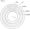
- FIG. 3 is a front view showing an example of a fuel injector used in the combustor in FIG. 2 ;
- FIG. 4 is a block diagram schematically showing an example of a fuel introduction system used in the combustor in FIG. 2 ;
- FIG. 5 is a flowchart showing an example of an operating method at startup of the combustor in FIG. 2 ;
- FIG. 6 is a graph schematically showing an example of a fuel flow rate profile by the operating method in FIG. 5 ;
- FIG. 7 is a graph schematically showing another example of the fuel flow rate profile by the operating method in FIG. 5 ;
- FIG. 8 is a graph schematically showing still another example of the fuel flow rate profile by the operating method in FIG. 5 ;
- FIG. 9 is a flowchart showing an example of an operating method during stopping of the combustor in FIG. 2 .
- FIG. 1 shows a schematic configuration of a gas turbine engine (hereinafter, simply referred to as a gas turbine) GT to which a combustor according to one embodiment of the present invention is applied.
- a gas turbine engine hereinafter, simply referred to as a gas turbine
- an air which has been introduced thereinto is compressed by a compressor 1 and guided into a combustor 3
- a fuel is injected into the combustor 3 and combusted
- a turbine 5 is driven by the obtained high-temperature and high-pressure combustion gas G
- the combustor 3 is, for example, a can-type combustor, and a plurality of such combustors are disposed annularly about the axis of the gas turbine GT.
- the turbine 5 is coupled to the compressor 1 via a rotation shaft 7 , and the compressor 1 is driven by the turbine 5 .
- a load L such as a rotor of an aircraft or a generator is driven.
- the compressor 1 side and the turbine 5 side in the axial direction of the gas turbine GT are referred to as “front side” and “rear side”, respectively.
- the combustor 3 includes: a combustion liner 13 that forms a combustion chamber 11 therein; a fuel injector 15 that is provided at a top portion (most upstream portion) 13 a of the combustion liner 13 and injects a fuel and an air into the combustion chamber 11 ; and a fuel supply system IS that introduces the fuel into the fuel injector 15 .
- a combustion liner 13 and the fuel injector 15 are concentrically housed in a substantially cylindrical housing H that is an outer tube of the combustor 3 .
- the combustor 3 is configured as a reverse-flow type in which the flow direction of air A and the flow direction of the combustion gas G are opposite to each other. That is, the combustor 3 has an air introduction passage 19 formed between the housing H and the combustion liner 13 and a support tube 17 that extends frontward from the combustion liner 13 in a tubular shape.
- the air introduction passage 19 introduces the air A compressed by the compressor 1 ( FIG. 1 ), in the direction opposite to the flow direction of the combustion gas G within the combustion chamber 11 .
- the combustor 3 may be of an axial-flow type in which the flow directions of the air A and the combustion gas G are the same.
- a plurality of air introduction holes 21 are provided in a front-end portion of a peripheral wall of the support tube 17 so as to be aligned in the circumferential direction.
- the air A supplied through the air introduction passage 19 is introduced through the air introduction holes 21 into an air supply passage 23 formed inside the support tube 17 , and supplied to the rear side, that is, in the direction toward the combustion chamber 11 .
- the fuel injector 15 includes a plurality of annular fuel injection portions 25 .
- three annular fuel injection portions 25 having diameter dimensions different from each other are arranged so as to be concentric with each other and be concentric with the combustor 3 ( FIG. 2 ).
- Multiple fuel injection holes 25 a are formed in each annular fuel injection portion 25 so as to be arranged at regular intervals in the circumferential direction thereof.
- air guides 27 for guiding the air A from the air supply passage 23 to mix the air and the fuel injected from the annular fuel injection portions 25 are disposed radially outward and inward of the respective annular fuel injection portions 25 .
- the fuel injected from the respective annular fuel injection portions 25 is premixed with the air guided by the air guides 27 , and injected as premixed gas into the combustion chamber 11 .
- the number of annular fuel injection portions 25 is not particularly limited as long as the number is not less than two.
- the combustor 3 of the present embodiment has a plurality of fuel supply passages capable of supplying fuel F to the respective annular fuel injection portions 25 of the fuel injector 15 .
- a fuel supply main pipe 29 is provided in the fuel injector 15 so as to extend from a center portion of the air supply passage 23 to the rear side of the housing H.
- the fuel supply main pipe 29 and the respective annular fuel injection portions 25 are connected to each other by fuel supply branch pipes 31 that branch from the fuel supply main pipe 29 independently of each other.
- the fuel supply main pipe 29 has a multi-pipe structure (double-pipe structure) in which two cylindrical pipes are concentrically disposed in layers.
- the internal space of the inner fuel supply pipe and the internal spaces of the fuel supply branch pipes 31 that communicate therewith form a first fuel supply passage 33
- the space between the inner and outer fuel supply pipes and the internal space of the fuel supply branch pipe 31 that communicates therewith form a second fuel supply passage 35 .
- a fuel is introduced from a fuel introduction system IS, which will be described later, into the respective fuel supply passages 33 and 35 within the fuel supply main pipe 29 .
- the fuel that has passed through the first fuel supply passage 33 is supplied to the two annular fuel injection portions 25 disposed at the radially inner side among the plurality of annular fuel injection portions 25 .
- the fuel F that has passed through the second fuel supply passage 35 is supplied through the one fuel supply branch pipe 31 connected to the second fuel supply passage 35 , to the one annular fuel injection portion 25 disposed at the radially outermost side among the plurality of annular fuel injection portions 25 .
- the multi-pipe structure of the fuel supply main pipe 29 is not limited to the example in FIG. 2 , as long as a plurality of fuel supply passages that are independent from each other can be formed using a plurality of pipes.
- the multi-pipe structure of the fuel supply main pipe 29 may be a multi-pipe structure in which, within one header having a large diameter, a plurality of fuel supply pipes having diameters that are smaller than that of the header and are equal to each other are provided so as to extend parallel to each other.
- a staging combustion can be achieved, in which a change in output of the gas turbine GT from a low load (partial load) to a high load (rated load) is suitably handled by dividing the annular fuel injection portions 25 into annular fuel injection portions 25 that perform fuel supply and the remaining annular fuel injection portions 25 that do not perform fuel supply.
- a change in output of the gas turbine GT from a low load (partial load) to a high load (rated load) is suitably handled by dividing the annular fuel injection portions 25 into annular fuel injection portions 25 that perform fuel supply and the remaining annular fuel injection portions 25 that do not perform fuel supply.
- handling load fluctuations by selecting annular fuel injection portions 25 that are operated and the remaining annular fuel injection portions 25 that are not operated is effective for stable low-NOx combustion, rather than by uniformly changing fuel supply amounts at all the annular fuel injection portions 25 .
- the fuel introduction system IS includes an auxiliary fuel introduction passage 41 , a first main fuel introduction passage 43 , and a second main fuel introduction passage 45 .
- the auxiliary fuel introduction passage 41 introduces an auxiliary fuel AF from an auxiliary fuel source 47 into the fuel injector 15 .
- the first main fuel introduction passage 43 and the second main fuel introduction passage 45 introduce a main fuel from a main fuel source 49 into the fuel injector 15 .
- the first main fuel introduction passage 43 and the second main fuel introduction passage 45 are connected to a common main fuel major passage 51 connected to the common main fuel source 49 .
- first main fuel introduction passage 43 and the second main fuel introduction passage 45 are provided so as to branch from the downstream end of the main fuel major passage 51 .
- the first main fuel introduction passage 43 and the second main fuel introduction passage 45 may be independently connected to separately-provided main fuel sources, respectively.
- the auxiliary fuel introduction passage 41 introduces the auxiliary fuel AF that is to be supplied to the annular fuel injection portion 25 disposed at the radially outermost side (hereinafter, referred to as “auxiliary fuel injection portion 25 A”) among the plurality of annular fuel injection portions 25 , into the fuel injector 15 .
- the first main fuel introduction passage 43 introduces the main fuel MF that is to be supplied to the annular fuel injection portions 25 other than the auxiliary fuel injection portion 25 A, that is, the two annular fuel injection portions 25 disposed at the radially inner side (hereinafter, referred to as main fuel injection portions 25 B) among the plurality of annular fuel injection portions 25 , into the fuel injector 15 .
- the second main fuel introduction passage 45 introduces the main fuel MF that is to be supplied to the auxiliary fuel injection portion 25 A, into the fuel injector 15 . That is, in the present embodiment, the auxiliary fuel introduction passage 41 and the second main fuel introduction passage 45 are connected to the second fuel supply passage 35 of the fuel injector 15 , and the second fuel supply passage 35 is formed as a common fuel supply passage that serves as a supply passage for supplying the auxiliary fuel AF to the auxiliary fuel injection portion 25 A and a supply passage for supplying the main fuel MF to the auxiliary fuel injection portion 25 A.
- the first main fuel introduction passage 43 is connected to the first fuel supply passage 33 of the fuel injector 15 , and the main fuel MF is supplied through the first fuel supply passage 33 to the two main fuel injection portions 25 B.
- the igniter P is attached to the combustion liner 13 , and the auxiliary fuel injection portion 25 A is disposed at the radially outermost side among the plurality of annular fuel injection portions 25 .
- the auxiliary fuel injection portion 25 A is located near the igniter P, and the auxiliary fuel can be assuredly ignited.
- the arrangement of the igniter P and the auxiliary fuel injection portion 25 A is not limited to this example.
- the annular fuel injection portion disposed at the radially innermost side among the plurality of annular fuel injection portions 25 may be formed as the auxiliary fuel injection portion 25 A (that is, may be configured to be supplied with the auxiliary fuel AF from the auxiliary fuel introduction passage 41 and be supplied with the main fuel MF from the second main fuel introduction passage 45 ).
- the auxiliary fuel injection portion 25 A does not need to be disposed in the vicinity of the igniter P.
- the number of auxiliary fuel injection portions 25 A is not limited to one, and may be two or more, as long as not all of the plurality of annular fuel injection portions 25 are auxiliary fuel injection portions 25 A.
- the main fuel MF is fuel having high reactivity and a wide combustible concentration range.
- the main fuel MF is hydrogen-containing gas, for example, hydrogen gas.
- the auxiliary fuel AF is fuel having lower reactivity and a narrower combustible concentration range than the main fuel MF, and may be used not only at startup of the combustor but also at the time of a low load such as during stopping of the combustor as described later.
- the auxiliary fuel AF is natural gas.
- the auxiliary fuel AF in addition to natural gas, for example, hydrocarbon fuel gas such as propane may be used.
- on-off valves (a first on-off valve 47 and a second on-off valve 49 ) are provided on upstream portions of the first main fuel introduction passage 43 and the second main fuel introduction passage 45 , respectively, and flow regulating valves (a first flow regulating valve 51 and a second flow regulating valve 53 ) are provided downstream of the on-off valves 47 and 49 , respectively.
- An on-off valve (third on-off valve 55 ) is provided on the main fuel major passage 51 .
- an on-off valve (fourth on-off valve 57 ) is provided on an upstream portion of the auxiliary fuel introduction passage 41 , and an orifice 59 for flow limitation is provided downstream of the fourth on-off valve 57 .
- the fuel introduction system IS includes a purge gas introduction passage 61 that introduces a purge gas PG into the first main fuel introduction passage 43 and the second main fuel introduction passage 45 .
- the purge gas introduction passage 61 is connected to a portion of the main fuel major passage 51 downstream of the third on-off valve 55 .
- the fuel introduction system IS includes an additional purge gas introduction passage 63 that branches from the auxiliary fuel introduction passage 41 and introduces the auxiliary fuel AF as a purge gas into the first main fuel introduction passage 43 and the second main fuel introduction passage 45 .
- the additional purge gas introduction passage 63 is also connected to the portion of the main fuel major passage 51 downstream of the third on-off valve 55 .
- purge gas PG for example, nitrogen gas having very low reactivity, inert gas, or the like may be used.
- the purge gas PG is supplied from a purge gas source 65 connected to the purge gas introduction passage 61 .
- the auxiliary fuel AF is injected from the auxiliary fuel introduction passage 41 through the second fuel supply passage 35 and the auxiliary fuel injection portion 25 A into the combustion chamber 11 , and the auxiliary fuel AF injected into the combustion chamber 11 is ignited by the igniter P ( FIG. 2 ) (auxiliary fuel ignition step S 1 ).
- the main fuel MF is injected from the first main fuel introduction passage 43 through the main fuel injection portions 25 B into the combustion chamber 11 while the flow rate of the main fuel MF is gradually increased by the first flow regulating valve 51 ( FIG. 4 ) (main fuel injection step S 2 ).
- main fuel injection step S 2 main fuel injection step S 3
- auxiliary fuel stop step S 3 the introduction of the auxiliary fuel AF from the auxiliary fuel introduction passage 41 is stopped.
- FIG. 6 shows a profile of a fuel flow rate in the case of operating the combustor 3 by the method described above.
- the horizontal axis represents time
- the vertical axis represents fuel flow rate.
- an alternate long and short dash line represents the flow rate of the auxiliary fuel AF passing through the auxiliary fuel introduction passage 41
- a solid line represents the flow rate of the main fuel MF passing through the first main fuel introduction passage 43
- a broken line represents the flow rate of the additional main fuel MF passing through the second main fuel introduction passage 45 .
- a flow regulating valve is not provided on the auxiliary fuel introduction passage 41 and control of whether or not to cause the auxiliary fuel AF to flow to the auxiliary fuel introduction passage 41 at a predetermined flow rate is enabled by a combination of the fourth on-off valve 57 and the orifice 59 .
- the example of the operating method through the auxiliary fuel introduction passage 41 is not limited thereto.
- a flow regulating valve may be provided downstream of the fourth on-off valve 57 on the auxiliary fuel introduction passage 41 , and introduction of the auxiliary fuel AF in the auxiliary fuel ignition step S 1 or stop of the introduction of the auxiliary fuel AF in the auxiliary fuel stop step S 3 may be performed while the flow rate of the auxiliary fuel AF is regulated.
- the introduction of the auxiliary fuel AF may be stopped in such a way that the flow rate of the auxiliary fuel AF is gradually decreased from the time point of start of injection of the main fuel MF.
- FIG. 7 the introduction of the auxiliary fuel AF may be stopped in such a way that the flow rate of the auxiliary fuel AF is gradually decreased from the time point of start of injection of the main fuel MF.
- the introduction of the auxiliary fuel AF may be stopped in such a way that the flow rate of the auxiliary fuel AF is gradually decreased from the time point of start of injection of the main fuel MF in the auxiliary fuel stop step S 3 .
- auxiliary fuel AF is injected from the auxiliary fuel introduction passage 41 through the auxiliary fuel injection portion 25 A into the combustion chamber 11 (auxiliary fuel reinjection step S 6 ).
- main fuel stop step S 7 the introduction of the main fuel MF from the first main fuel introduction passage 43 is stopped.
- main fuel stop step S 7 the supply of the auxiliary fuel AF from the auxiliary fuel introduction passage 41 is stopped (auxiliary fuel final stop step S 8 ). Accordingly, the operation of the combustor 3 is stopped.
- steps S 5 to S 8 are a basic procedure for stopping the operation of the combustor 3 . During stopping of the combustor 3 , the following steps for purging the main fuel MF may be further performed.
- the purge gas PG is introduced from the purge gas introduction passage 61 into the first main fuel introduction passage 43 and the second main fuel introduction passage 45 (purge gas introduction step S 9 ).
- the purge gas PG is introduced from the purge gas introduction passage 61 through the main fuel major passage 51 into the first main fuel introduction passage 43 and the second main fuel introduction passage 45 .
- the introduction amount (total flow amount) of the purge gas PG at the purge gas introduction passage 61 from the purge gas introduction step S 9 to the remaining main fuel combustion step S 10 the main fuel MF remaining within the main fuel major passage 51 , the first main fuel introduction passage 43 , the second main fuel introduction passage 45 , and the first fuel supply passage 33 can be completely discharged into the combustion chamber 11 .
- the auxiliary fuel AF may be further introduced from the additional purge gas introduction passage 63 into the first main fuel introduction passage 43 and the second main fuel introduction passage 45 using the additional purge gas introduction passage 63 (additional purge step S 11 ).
- the purge gas introduction step S 9 may be omitted, and the additional purge step S 11 may be performed before shifting to the remaining fuel combustion step S 10 .
- the purge gas introduction passage 61 and the additional purge gas introduction passage 63 are provided in the combustor 3 , and, in the operating method of the combustor 3 , the main fuel passages can be purged, while the main fuel MF is being combusted, by performing steps S 9 to S 11 for purging the main fuel MF using these passages 61 and 63 .
- unburned gas of the main fuel having a high reaction rate and a wide combustible concentration range can be prevented from remaining in the combustor 3 after stop of the combustor 3 .
- auxiliary fuel AF is enabled by connecting the auxiliary fuel introduction passage 41 to a part of the plurality of annular fuel injection portions 25 (the auxiliary fuel injection portion 25 B), stable combustion can be achieved even at startup or stop of the combustor 3 , at which the combustor 3 is in a low-load state, by supplying fuel having lower reactivity than the main fuel MF such as natural gas as the auxiliary fuel AF. Therefore, stable operation of the combustor and stable engine operation can be maintained while generation of unburned gas and a problem due to generation of unburned gas are suppressed.
- the can-type combustor 3 has been described as an example, but the above configuration may be applied to other types of combustors, for example, an annular type combustor.
Landscapes
- Engineering & Computer Science (AREA)
- Chemical & Material Sciences (AREA)
- Combustion & Propulsion (AREA)
- Mechanical Engineering (AREA)
- General Engineering & Computer Science (AREA)
Abstract
Description
-
- 3 . . . Combustor
- 11 . . . Combustion chamber
- 13 . . . Combustion liner
- 15 . . . Fuel injector
- 25 . . . Annular fuel injection portion
- 25A . . . Auxiliary fuel injection portion
- 25B . . . Main fuel injection portion
- 35 . . . Second fuel supply passage (common fuel supply passage)
- 41 . . . Auxiliary fuel introduction passage
- 43 . . . First main fuel introduction passage
- 45 . . . Second main fuel introduction passage
- 51 . . . First flow regulating valve
- 61 . . . Purge gas introduction passage
- 63 . . . Additional purge gas introduction passage
- AF . . . Auxiliary fuel
- MF . . . Main fuel
- P . . . Igniter
Claims (2)
Applications Claiming Priority (4)
| Application Number | Priority Date | Filing Date | Title |
|---|---|---|---|
| JPJP2017-096984 | 2017-05-16 | ||
| JP2017096984A JP6978855B2 (en) | 2017-05-16 | 2017-05-16 | Gas turbine combustor and its operation method |
| JP2017-096984 | 2017-05-16 | ||
| PCT/JP2018/017549 WO2018212001A1 (en) | 2017-05-16 | 2018-05-02 | Gas turbine combustor and operating method thereof |
Related Parent Applications (1)
| Application Number | Title | Priority Date | Filing Date |
|---|---|---|---|
| PCT/JP2018/017549 Continuation WO2018212001A1 (en) | 2017-05-16 | 2018-05-02 | Gas turbine combustor and operating method thereof |
Publications (2)
| Publication Number | Publication Date |
|---|---|
| US20200080480A1 US20200080480A1 (en) | 2020-03-12 |
| US11421599B2 true US11421599B2 (en) | 2022-08-23 |
Family
ID=64273717
Family Applications (1)
| Application Number | Title | Priority Date | Filing Date |
|---|---|---|---|
| US16/680,718 Active 2038-06-18 US11421599B2 (en) | 2017-05-16 | 2019-11-12 | Gas turbine combustor and operating method thereof |
Country Status (4)
| Country | Link |
|---|---|
| US (1) | US11421599B2 (en) |
| JP (1) | JP6978855B2 (en) |
| DE (1) | DE112018002520B4 (en) |
| WO (1) | WO2018212001A1 (en) |
Cited By (2)
| Publication number | Priority date | Publication date | Assignee | Title |
|---|---|---|---|---|
| US20240125476A1 (en) * | 2021-01-08 | 2024-04-18 | Mitsubishi Heavy Industries, Ltd. | Gas turbine combustor and gas turbine |
| US12535039B2 (en) | 2024-01-11 | 2026-01-27 | General Electric Company | Methods and apparatus to regulate a gaseous fuel system |
Families Citing this family (16)
| Publication number | Priority date | Publication date | Assignee | Title |
|---|---|---|---|---|
| US11391214B2 (en) | 2019-05-15 | 2022-07-19 | Pratt & Whitney Canada Corp. | System and method for purging a fuel manifold of a gas turbine engine using a flow divider assembly |
| US11486303B2 (en) * | 2019-05-15 | 2022-11-01 | Pratt & Whitney Canada Corp. | System and method for purging a fuel manifold of a gas turbine engine using a pump |
| JP7200077B2 (en) * | 2019-10-01 | 2023-01-06 | 三菱重工業株式会社 | Gas turbine combustor and its operation method |
| US11346281B2 (en) * | 2020-08-21 | 2022-05-31 | Woodward, Inc. | Dual schedule flow divider valve, system, and method for use therein |
| KR102912281B1 (en) * | 2021-03-25 | 2026-01-13 | 미츠비시 파워 가부시키가이샤 | Fuel control unit of gas turbine |
| EP4163481B1 (en) * | 2021-09-17 | 2023-11-01 | Rolls-Royce plc | Fuel delivery system |
| US12352218B2 (en) * | 2022-02-01 | 2025-07-08 | General Electric Company | Fuel supply system for a combustor |
| US11649966B1 (en) * | 2022-02-17 | 2023-05-16 | General Electric Company | Combustor with an ignition tube |
| GB202205354D0 (en) | 2022-04-12 | 2022-05-25 | Rolls Royce Plc | Fuel delivery |
| GB202205358D0 (en) | 2022-04-12 | 2022-05-25 | Rolls Royce Plc | Loading parameters |
| GB202205356D0 (en) * | 2022-04-12 | 2022-05-25 | Rolls Royce Plc | transitional range |
| GB202205355D0 (en) * | 2022-04-12 | 2022-05-25 | Rolls Royce Plc | Gas turbine operation |
| US12473862B2 (en) * | 2022-05-13 | 2025-11-18 | General Electric Company | Purge system for a hydrogen fuel system |
| JP2024108852A (en) | 2023-01-31 | 2024-08-13 | トヨタ自動車株式会社 | Gas turbine that can use hydrogen as fuel |
| JP2024108853A (en) | 2023-01-31 | 2024-08-13 | トヨタ自動車株式会社 | Gas turbine that can use hydrogen as fuel |
| CN117307325B (en) * | 2023-11-14 | 2025-11-07 | 中国航发燃气轮机有限公司 | Fuel supply system and method for gas turbine |
Citations (6)
| Publication number | Priority date | Publication date | Assignee | Title |
|---|---|---|---|---|
| US5660045A (en) * | 1994-07-20 | 1997-08-26 | Hitachi, Ltd. | Gas turbine combustor and gas turbine |
| US20090272118A1 (en) | 2008-05-05 | 2009-11-05 | General Electric Company | Operation of Dual Gas Turbine Fuel System |
| US20120258409A1 (en) | 2011-04-11 | 2012-10-11 | Mansour Adel B | Distributed injection with fuel flexible micro-mixing injectors |
| US20130186057A1 (en) * | 2012-01-25 | 2013-07-25 | Venkadesh Shanmugam | Naphtha and process gas/syngas mixture firing method for gas turbine engines |
| WO2015182727A1 (en) | 2014-05-30 | 2015-12-03 | 川崎重工業株式会社 | Combustion device for gas turbine engine |
| FR3032010A1 (en) | 2015-01-27 | 2016-07-29 | Snecma | DEVICE FOR SUPPLYING A COMBUSTION CHAMBER OF AN AIRCRAFT ENGINE |
Family Cites Families (4)
| Publication number | Priority date | Publication date | Assignee | Title |
|---|---|---|---|---|
| US258409A (en) | 1882-05-23 | Washing-machine | ||
| JP2006138566A (en) * | 2004-11-15 | 2006-06-01 | Hitachi Ltd | Gas turbine combustor and liquid fuel injection nozzle thereof |
| WO2014092185A1 (en) * | 2012-12-13 | 2014-06-19 | 川崎重工業株式会社 | Multi-fuel-capable gas turbine combustor |
| JP6318276B2 (en) | 2017-02-10 | 2018-04-25 | サターン ライセンシング エルエルシーSaturn Licensing LLC | Information processing apparatus and information processing method |
-
2017
- 2017-05-16 JP JP2017096984A patent/JP6978855B2/en active Active
-
2018
- 2018-05-02 DE DE112018002520.9T patent/DE112018002520B4/en active Active
- 2018-05-02 WO PCT/JP2018/017549 patent/WO2018212001A1/en not_active Ceased
-
2019
- 2019-11-12 US US16/680,718 patent/US11421599B2/en active Active
Patent Citations (9)
| Publication number | Priority date | Publication date | Assignee | Title |
|---|---|---|---|---|
| US5660045A (en) * | 1994-07-20 | 1997-08-26 | Hitachi, Ltd. | Gas turbine combustor and gas turbine |
| US20090272118A1 (en) | 2008-05-05 | 2009-11-05 | General Electric Company | Operation of Dual Gas Turbine Fuel System |
| JP2009270574A (en) | 2008-05-05 | 2009-11-19 | General Electric Co <Ge> | Method of operating dual-gas turbine fuel system |
| US7921651B2 (en) * | 2008-05-05 | 2011-04-12 | General Electric Company | Operation of dual gas turbine fuel system |
| US20120258409A1 (en) | 2011-04-11 | 2012-10-11 | Mansour Adel B | Distributed injection with fuel flexible micro-mixing injectors |
| US20130186057A1 (en) * | 2012-01-25 | 2013-07-25 | Venkadesh Shanmugam | Naphtha and process gas/syngas mixture firing method for gas turbine engines |
| WO2015182727A1 (en) | 2014-05-30 | 2015-12-03 | 川崎重工業株式会社 | Combustion device for gas turbine engine |
| US20170074521A1 (en) * | 2014-05-30 | 2017-03-16 | Kawasaki Jukogyo Kabushiki Kaisha | Combustion device for gas turbine engine |
| FR3032010A1 (en) | 2015-01-27 | 2016-07-29 | Snecma | DEVICE FOR SUPPLYING A COMBUSTION CHAMBER OF AN AIRCRAFT ENGINE |
Cited By (3)
| Publication number | Priority date | Publication date | Assignee | Title |
|---|---|---|---|---|
| US20240125476A1 (en) * | 2021-01-08 | 2024-04-18 | Mitsubishi Heavy Industries, Ltd. | Gas turbine combustor and gas turbine |
| US12435878B2 (en) * | 2021-01-08 | 2025-10-07 | Mitsubishi Heavy Industries, Ltd. | Gas turbine combustor with less combustable fuel and highly combustible fuel ratio control |
| US12535039B2 (en) | 2024-01-11 | 2026-01-27 | General Electric Company | Methods and apparatus to regulate a gaseous fuel system |
Also Published As
| Publication number | Publication date |
|---|---|
| JP6978855B2 (en) | 2021-12-08 |
| DE112018002520B4 (en) | 2024-10-17 |
| US20200080480A1 (en) | 2020-03-12 |
| DE112018002520T5 (en) | 2020-02-13 |
| WO2018212001A1 (en) | 2018-11-22 |
| JP2018194210A (en) | 2018-12-06 |
Similar Documents
| Publication | Publication Date | Title |
|---|---|---|
| US11421599B2 (en) | Gas turbine combustor and operating method thereof | |
| EP3217097B1 (en) | Burner, combustor, and gas turbine | |
| US20190162414A1 (en) | Gas turbine combustor | |
| US5722230A (en) | Center burner in a multi-burner combustor | |
| US10060625B2 (en) | Gas turbine combustor | |
| CN110878947A (en) | Gas turbine combustor | |
| US20150275755A1 (en) | Multi-fuel-capable gas turbine combustor | |
| US20240384873A1 (en) | Trapped vortex combustor and method for operating the same | |
| US9163840B2 (en) | Gas turbine combustor and fuel supply method used for the same | |
| US20170307210A1 (en) | Gas turbine combustor and gas turbine | |
| JP2012229697A (en) | Method and apparatus for combusting fuel within gas turbine engine | |
| JP4997217B2 (en) | Gas turbine operating method and gas turbine combustor | |
| CN104373960A (en) | Sequential combustion with dilution gas mixer | |
| US12404813B2 (en) | Control method for gas turbine combustor and control device for gas turbine combustor | |
| US20140007582A1 (en) | Gas Turbine Combustor and Operating Method for Gas Turbine Combustor | |
| EP4202308B1 (en) | Gas turbine for power plant comprising a premix burner suitable to be fed with common and highly reactive fuels and method for operating the same | |
| JP2013177996A (en) | Gas turbine combustor, operation method of gas turbine combustor and burner for gas turbine combustor | |
| JP4854613B2 (en) | Combustion apparatus and gas turbine combustor | |
| US20240263590A1 (en) | Fuel system with pilot and main injectors for hydrogen-driven gas turbine engine | |
| KR20090067122A (en) | Method for controlled purging of fuel supply system in combustor of gas turbine | |
| US10697638B2 (en) | Fuel injection device | |
| JP7167772B2 (en) | combustor | |
| WO2025182534A1 (en) | Control device and control method for gas turbine engine | |
| CN111623373B (en) | Sequential combustor for a gas turbine, method for operating the same and method for refurbishing the same | |
| EP3702669B1 (en) | Method for operating a sequential combustor of a gas turbine and a gas turbine comprising this sequential combustor |
Legal Events
| Date | Code | Title | Description |
|---|---|---|---|
| FEPP | Fee payment procedure |
Free format text: ENTITY STATUS SET TO UNDISCOUNTED (ORIGINAL EVENT CODE: BIG.); ENTITY STATUS OF PATENT OWNER: LARGE ENTITY |
|
| AS | Assignment |
Owner name: KAWASAKI JUKOGYO KABUSHIKI KAISHA, JAPAN Free format text: ASSIGNMENT OF ASSIGNORS INTEREST;ASSIGNORS:HORIKAWA, ATUSHI;KAZARI, MASAHIDE;OKADA, KUNIO;AND OTHERS;SIGNING DATES FROM 20191130 TO 20191211;REEL/FRAME:051706/0521 |
|
| STPP | Information on status: patent application and granting procedure in general |
Free format text: NON FINAL ACTION MAILED |
|
| STPP | Information on status: patent application and granting procedure in general |
Free format text: RESPONSE TO NON-FINAL OFFICE ACTION ENTERED AND FORWARDED TO EXAMINER |
|
| STPP | Information on status: patent application and granting procedure in general |
Free format text: FINAL REJECTION MAILED |
|
| STPP | Information on status: patent application and granting procedure in general |
Free format text: ADVISORY ACTION MAILED |
|
| STPP | Information on status: patent application and granting procedure in general |
Free format text: DOCKETED NEW CASE - READY FOR EXAMINATION |
|
| STPP | Information on status: patent application and granting procedure in general |
Free format text: NOTICE OF ALLOWANCE MAILED -- APPLICATION RECEIVED IN OFFICE OF PUBLICATIONS |
|
| STPP | Information on status: patent application and granting procedure in general |
Free format text: PUBLICATIONS -- ISSUE FEE PAYMENT VERIFIED |
|
| STCF | Information on status: patent grant |
Free format text: PATENTED CASE |
|
| MAFP | Maintenance fee payment |
Free format text: PAYMENT OF MAINTENANCE FEE, 4TH YEAR, LARGE ENTITY (ORIGINAL EVENT CODE: M1551); ENTITY STATUS OF PATENT OWNER: LARGE ENTITY Year of fee payment: 4 |