US11414125B2 - Steering controller and steering control method - Google Patents
Steering controller and steering control method Download PDFInfo
- Publication number
- US11414125B2 US11414125B2 US16/697,851 US201916697851A US11414125B2 US 11414125 B2 US11414125 B2 US 11414125B2 US 201916697851 A US201916697851 A US 201916697851A US 11414125 B2 US11414125 B2 US 11414125B2
- Authority
- US
- United States
- Prior art keywords
- steering
- torque
- operation amount
- angle
- electric motor
- Prior art date
- Legal status (The legal status is an assumption and is not a legal conclusion. Google has not performed a legal analysis and makes no representation as to the accuracy of the status listed.)
- Active, expires
Links
Images
Classifications
-
- B—PERFORMING OPERATIONS; TRANSPORTING
- B62—LAND VEHICLES FOR TRAVELLING OTHERWISE THAN ON RAILS
- B62D—MOTOR VEHICLES; TRAILERS
- B62D5/00—Power-assisted or power-driven steering
- B62D5/04—Power-assisted or power-driven steering electrical, e.g. using an electric servo-motor connected to, or forming part of, the steering gear
-
- B—PERFORMING OPERATIONS; TRANSPORTING
- B62—LAND VEHICLES FOR TRAVELLING OTHERWISE THAN ON RAILS
- B62D—MOTOR VEHICLES; TRAILERS
- B62D5/00—Power-assisted or power-driven steering
- B62D5/04—Power-assisted or power-driven steering electrical, e.g. using an electric servo-motor connected to, or forming part of, the steering gear
- B62D5/0457—Power-assisted or power-driven steering electrical, e.g. using an electric servo-motor connected to, or forming part of, the steering gear characterised by control features of the drive means as such
- B62D5/046—Controlling the motor
- B62D5/0463—Controlling the motor calculating assisting torque from the motor based on driver input
-
- B—PERFORMING OPERATIONS; TRANSPORTING
- B62—LAND VEHICLES FOR TRAVELLING OTHERWISE THAN ON RAILS
- B62D—MOTOR VEHICLES; TRAILERS
- B62D5/00—Power-assisted or power-driven steering
- B62D5/04—Power-assisted or power-driven steering electrical, e.g. using an electric servo-motor connected to, or forming part of, the steering gear
- B62D5/0421—Electric motor acting on or near steering gear
- B62D5/0424—Electric motor acting on or near steering gear the axes of motor and final driven element of steering gear, e.g. rack, being parallel
-
- B—PERFORMING OPERATIONS; TRANSPORTING
- B62—LAND VEHICLES FOR TRAVELLING OTHERWISE THAN ON RAILS
- B62D—MOTOR VEHICLES; TRAILERS
- B62D6/00—Arrangements for automatically controlling steering depending on driving conditions sensed and responded to, e.g. control circuits
-
- B—PERFORMING OPERATIONS; TRANSPORTING
- B62—LAND VEHICLES FOR TRAVELLING OTHERWISE THAN ON RAILS
- B62D—MOTOR VEHICLES; TRAILERS
- B62D6/00—Arrangements for automatically controlling steering depending on driving conditions sensed and responded to, e.g. control circuits
- B62D6/008—Control of feed-back to the steering input member, e.g. simulating road feel in steer-by-wire applications
-
- H—ELECTRICITY
- H02—GENERATION; CONVERSION OR DISTRIBUTION OF ELECTRIC POWER
- H02P—CONTROL OR REGULATION OF ELECTRIC MOTORS, ELECTRIC GENERATORS OR DYNAMO-ELECTRIC CONVERTERS; CONTROLLING TRANSFORMERS, REACTORS OR CHOKE COILS
- H02P6/00—Arrangements for controlling synchronous motors or other dynamo-electric motors using electronic commutation dependent on the rotor position; Electronic commutators therefor
- H02P6/08—Arrangements for controlling the speed or torque of a single motor
-
- H—ELECTRICITY
- H02—GENERATION; CONVERSION OR DISTRIBUTION OF ELECTRIC POWER
- H02P—CONTROL OR REGULATION OF ELECTRIC MOTORS, ELECTRIC GENERATORS OR DYNAMO-ELECTRIC CONVERTERS; CONTROLLING TRANSFORMERS, REACTORS OR CHOKE COILS
- H02P2205/00—Indexing scheme relating to controlling arrangements characterised by the control loops
- H02P2205/05—Torque loop, i.e. comparison of the motor torque with a torque reference
Definitions
- the present disclosure relates to a steering controller and a steering control method for operating a steering actuator that steers steerable wheels and incorporates an electric motor.
- Japanese Laid-Open Patent Publication No. 2006-151360 describes an example of a steering controller for setting the torque of an electric motor incorporated in a steering actuator that steers steerable wheels.
- the steering controller executes feedback control to adjust a steering angle detected by a steering sensor to a target steering angle.
- the torque of the electric motor is set based on an operation amount used for the feedback control.
- the target steering angle is set based on a steering torque detected by a steering torque sensor.
- Noise is superimposed on the state quantities detected by various sensors.
- the state quantities include, for example, a steering torque detected by the steering torque sensor and a steering angle detected by the steering sensor.
- the superimposition of the noise of the steering torque and the noise of the steering angle may increase the influence of noise on a control unit that executes the feedback control.
- Example 1 A steering controller for operating a steering actuator that incorporates an electric motor and steers a steerable wheel is provided.
- the steering controller includes processing circuitry configured to execute a torque feedback process for calculating a steering-side operation amount, the steering-side operation amount being used for feedback control that adjusts a steering torque input by a driver to a target torque and being convertible into torque required for the electric motor, an angle command value calculation process for calculating an angle command value based on the steering-side operation amount, the angle command value being a command value of a convertible angle that is convertible into a steerable angle of the steerable wheel, an angle feedback control process for calculating a steerable wheel-side operation amount, the steerable wheel-side operation amount being used for feedback control that adjusts the convertible angle to the angle command value and being convertible into the torque required for the electric motor, and an operation process for calculating a torque command value corresponding to a sum of an amount by which the steering-side operation amount is converted into the torque required for the electric motor and an amount by which the steerable wheel-side operation amount is
- noise may be superimposed on the steering torque that is an input of the torque feedback process.
- the angle command value is calculated based on the steering-side operation amount, which is calculated through the torque feedback process.
- the angle feedback process is performed based on the angle command value.
- the angle feedback process is affected by the noise of the steering torque included in the angle command value in addition to the noise superimposed on the convertible angle.
- the responsivity of the angle feedback process cannot be increased easily.
- the torque command value of the electric motor corresponds to both the steering-side operation amount and the steerable wheel-side operation amount instead of being determined only from the steerable wheel-side operation amount. This increases the responsivity of control.
- Example 2 In the steering controller according to Example 1, the angle feedback control process includes an angle estimation process for calculating an estimated value of the convertible angle based on the convertible angle and the torque required for the electric motor and a process for adjusting the estimated value to the angle command value through feedback control.
- the state quantity used for the feedback control is the estimated value estimated through the angle estimation process instead of the convertible angle based on a sensor detection value. This reduces the influence of the noise superimposed on the convertible angle on the angle feedback process.
- Example 3 In the steering controller according to Example 1 or 2, the angle feedback control process includes calculating a feedback operation amount using a differential element, obtaining an additional value by adding, to the feedback operation amount, a feedforward operation amount based on a second order time differential value of the angle command value, and calculating the steerable wheel-side operation amount based on the additional value.
- the feedback operation amount is calculated using a differential element.
- the responsivity of control based on the feedback operation amount is improved.
- the steerable wheel-side operation amount is calculated using the feedforward operation amount.
- the responsivity of control based on the steerable wheel-side operation amount is improved.
- Example 4 In the steering controller according to any one of Examples 1 to 3, the processing circuitry is configured to execute a target torque calculation process for calculating the target torque, and the target torque calculation process includes obtaining a conversion amount by converting each of the steering-side operation amount and the steering torque into force acting on a same object and calculating the target torque based on a sum of the conversion amounts.
- the steering-side operation amount can be converted into the torque required for the electric motor.
- the steering-side operation amount and the steering torque determine the force applied from the vehicle to steer the steerable wheel. This force determines the side force.
- the target torque required to improve the steering feeling by the driver tends to be determined by the side force.
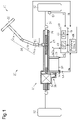
- FIG. 1 is a diagram showing an electric power steering according to an embodiment.
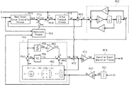
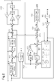
- FIG. 2 is a block diagram illustrating processes executed by the steering controller of the embodiment.
- Exemplary embodiments may have different forms, and are not limited to the examples described. However, the examples described are thorough and complete, and convey the full scope of the disclosure to one of ordinary skill in the art.
- a steering controller 40 according to an embodiment will now be described with reference to the drawings.
- an electric power steering 10 includes a steering mechanism 20 , which steers steerable wheels 12 based on the operation of a steering wheel 22 performed by a driver, and a steering actuator 30 , which electrically steers the steerable wheels 12 .
- the steering mechanism 20 includes the steering wheel 22 , a steering shaft 24 , which is fixed to the steering wheel 22 , and a rack-and-pinion mechanism 27 .
- the steering shaft 24 includes a column shaft 24 a , which is coupled to the steering wheel 22 , an intermediate shaft 24 b , which is coupled to the lower end of the column shaft 24 a , and a pinion shaft 24 c , which is coupled to the lower end of the intermediate shaft 24 b.
- the lower end of the pinion shaft 24 c is coupled to a rack shaft 26 , which is a steerable shaft, by the rack-and-pinion mechanism 27 .
- the rack-and-pinion mechanism 27 includes the pinion shaft 24 c and the rack shaft 26 .
- the opposite ends of the rack shaft 26 are respectively coupled to the left and right steerable wheels 12 by a tie rod 28 .
- the rack-and-pinion mechanism 27 converts rotation of the steering wheel 22 (i.e., rotation of the steering shaft 24 ) into reciprocation of the rack shaft 26 in the axial direction.
- the reciprocation is transmitted to the steerable wheels 12 from the tie rod 28 , which is coupled to the opposite ends of the rack shaft 26 , thereby changing the steerable angles of the steerable wheels 12 .
- the axial direction of the rack shaft 26 corresponds to the sideward direction in FIG. 1 .
- the steering actuator 30 shares the rack shaft 26 with the steering mechanism 20 . Further, the steering actuator 30 includes an electric motor 32 , an inverter 33 , a ball screw mechanism 34 , and a belt reduction drive 36 .
- the electric motor 32 is the generator of power that steers the steerable wheels 12 .
- a three-phase surface permanent magnet synchronous motor (SPMSM) is exemplified as the electric motor 32 .
- the ball screw mechanism 34 is arranged around the rack shaft 26 and coupled to the rack shaft 26 .
- the belt reduction drive 36 transmits rotation force of an output shaft 32 a of the electric motor 32 to the ball screw mechanism 34 .
- the ball screw mechanism 34 and the belt reduction drive 36 convert the rotation force of the output shaft 32 a of the electric motor 32 into force that reciprocates the rack shaft 26 in the axial direction. The axial force given to the rack shaft 26 steers the steerable wheels 12 .
- the steering controller 40 controls the steerable wheels 12 .
- the steering controller 40 operates the steering actuator 30 in order to control a steerable angle, which is the control amount of each steerable wheel 12 .
- the steering controller 40 refers to the state quantities detected by various sensors.
- the state quantities include a steering torque Th, which is detected by a torque sensor 50 , and a vehicle speed V, which is detected by a vehicle speed sensor 52 .
- the steering torque Th is input by the driver via the steering wheel 22 .
- the state quantities also include a rotation angle ⁇ m of the output shaft 32 a , which is detected by a rotation angle sensor 54 .
- the state quantities further include current iu, current iv, and current iw, which flow through the electric motor 32 .
- the current iu, the current iv, and the current iw can be detected based on voltage drop caused by the shunt resistor of each leg of the inverter 33 .
- the steering controller 40 includes a CPU 42 , a ROM 44 , and a peripheral circuit 46 .
- the CPU 42 , the ROM 44 , and the peripheral circuit 46 are connected to one another by a communication line 48 .
- the peripheral circuit 46 includes various circuits such as a circuit that generates a clock signal specifying an internal operation, a power supply circuit, and a reset circuit.
- FIG. 2 shows part of the processes executed by the steering controller 40 .
- the processes of FIG. 2 are implemented by the CPU 42 executing programs stored in the ROM 44 .
- a base target torque calculation process M 10 is a process for calculating a base target torque Thb* based on an axial force Taf, which will be described later.
- the base target torque Thb* is the base value of a target torque Th*, which should be input by the driver to the steering shaft 24 via the steering wheel 22 .
- the axial force Taf is applied to the rack shaft 26 in the axial direction.
- the axial force Taf has an amount corresponding to a side force acting on each steerable wheel 12 .
- the side force can be obtained from the axial force Taf. It is desired that the side force be used to determine the torque that should be input by the driver to the steering shaft 24 via the steering wheel 22 . Accordingly, the base target torque calculation process M 10 calculates the base target torque Thb* in accordance with the side force obtained from the axial force Taf.
- the base target torque calculation process M 10 calculates the absolute value of the base target torque Thb* to be smaller when the vehicle speed V is low than when the vehicle speed V is high.
- This can be achieved by, for example, the CPU 42 obtaining the base target torque Thb* through map calculation in a state in which map data is stored in the ROM 44 in advance.
- map data for example, the axial force Taf or a lateral acceleration obtained from the axial force Taf, and the vehicle speed V are set as input variables, and the base target torque Thb* is set as an output variable.
- the map data refers to a data set of discrete values of input variables and values of output variables each corresponding to a value of the input variables.
- the map calculation uses the value of the corresponding output variable of the map data as the calculation result.
- the value of the input variable does not match any of the values of the input variable on the map data, a value obtained by interpolation of multiple values of the output variable included in the map data is used as the calculation result.
- a hysteresis process M 14 is a process for calculating and outputting a hysteresis correction amount Thys, which is used to correct the base target torque Thb*, based on a pinion angle ⁇ p, which is the rotation angle of the pinion shaft 24 c .
- the pinion angle ⁇ p is a convertible angle that can be converted into the steerable angle of each steerable wheel 12 .
- the hysteresis process M 14 includes a process for calculating the hysteresis correction amount Thys such that the absolute value of the target torque Th* is larger when steering the steering wheel 22 than when returning the steering wheel 22 .
- the hysteresis process M 14 distinguishes the steering period from the returning period of the steering wheel 22 based on, for example, changes in the pinion angle ⁇ p.
- the hysteresis process M 14 includes a process for variably setting the hysteresis correction amount Thys in accordance with the vehicle speed V.
- An addition process M 12 is a process for calculating the target torque Th* by adding the hysteresis correction amount Thys to the base target torque Thb*.
- a difference calculation process M 16 is a process for calculating a difference ⁇ Th by subtracting the target torque Th* from the steering torque Th.
- a torque feedback process M 18 is a process for calculating a steering-side operation amount Ts* based on the difference ⁇ Th.
- the steering-side operation amount Ts* is an operation amount for adjusting the steering torque Th to the target torque Th*.
- the steering-side operation amount Ts* includes an operation amount used for feedback control that adjusts the steering torque Th to the target torque Th*, i.e., a feedback operation amount.
- the feedback operation amount is used to increase a required torque for the electric motor 32 when, for example, the steering torque Th and the target torque Th* are both positive and the steering torque Th is larger than the target torque Th*.
- the steering-side operation amount Ts* is an amount corresponding to the required torque for the electric motor 32 and is also an amount converted into torque applied to the steering shaft 24 in the present embodiment.
- An axial force calculation process M 20 is a process for calculating the axial force Taf by adding the steering torque Th to the steering-side operation amount Ts*.
- the steering torque Th is applied to the steering shaft 24 .
- the axial force Taf has a value obtained by converting, into the torque applied to the steering shaft 24 , force applied in the axial direction of the rack shaft 26 .
- the model represented by the expression (c1) is obtained by modelling a value indicated by the pinion angle ⁇ p when the steering shaft 24 receives the torque having the same amount as the axial force Taf.
- a viscosity coefficient C is obtained by modelling, for example, friction of the electric power steering 10 .
- An inertia coefficient J is obtained by modelling the inertia of the electric power steering 10 .
- a spring coefficient K is obtained by modelling the specification of the suspension or wheel alignment of a vehicle incorporating the electric power steering 10 .
- An integration process M 40 is a process for calculating an integration value In ⁇ of the rotation angle ⁇ m of the electric motor 32 .
- the steerable angle of the steerable wheel 12 is set to 0 when the vehicle travels straight, and the integration value In ⁇ is set to 0 when the steerable angle is 0.
- a conversion process M 42 is a process for calculating the pinion angle ⁇ p by dividing the integration value In ⁇ by a deceleration ratio Km from the steering shaft 24 to the electric motor 32 .
- An angle feedback process M 50 is a process for calculating a steerable wheel-side operation amount Tt*, which is an operation amount for adjusting the pinion angle ⁇ p to the pinion angle command value ⁇ p*.
- the angle feedback process M 50 includes a disturbance observer M 52 , which estimates a disturbance torque Tld by setting the pinion angle ⁇ p as an input, that is, based on the pinion angle ⁇ p.
- the disturbance torque Tld is excluded from the torque that affects the pinion angle ⁇ p other than the torque output by the electric motor 32 .
- an estimated disturbance torque Tld is converted into the torque added to the steering shaft 24 .
- the disturbance observer M 52 estimates the disturbance torque Tld with the following expression (c2) using a required torque Td for the electric motor 32 , which has been converted into the torque added to the steering shaft 24 .
- J ⁇ p*′′ d+Tld (c2)
- the disturbance ob server M 52 calculates the estimated disturbance torque Tld and an estimated value ⁇ pe with the following expression (c3) using a matrix L with three rows and one column, which specifies the estimated value ⁇ pe of the pinion angle ⁇ p, the required torque Td, and an observer gain.
- a difference calculation process M 54 is a process for obtaining a difference ⁇ p by subtracting the estimated value ⁇ pe from the pinion angle command value ⁇ p*.
- a feedback term calculation process M 56 is a process for calculating a feedback operation amount Ttfb, which is the sum of the output value of a proportional element having the difference ⁇ p as an input and the output value of a differential element having the differential value of the difference ⁇ p as an input. That is, the feedback operation amount Ttfb is the sum of a proportional element obtained in accordance with the difference ⁇ p and a differential element obtained in accordance with the differential value of the difference ⁇ p.
- a second order differential process M 58 is a process for calculating a second order time differential value of the pinion angle command value ⁇ p*.
- a first feedforward term calculation process M 60 is a process for calculating a first feedforward operation amount Ttff by multiplying an output value of the second order differential process M 58 by the inertia coefficient J.
- a two-degree-of-freedom operation amount calculation process M 62 is a process for calculating the steerable wheel-side operation amount Tt* by adding the feedback operation amount Ttfb, the first feedforward operation amount Ttff, and the estimated disturbance torque Tld, which is a second feedforward operation amount.
- An addition process M 70 is a process for calculating the required torque Td for the electric motor 32 by adding the steering-side operation amount Ts* and the steerable wheel-side operation amount Tt*.
- a conversion process M 72 is a process for converting the required torque Td into a motor torque command value Tm*, which is a command value of the torque for the electric motor 32 , by dividing the required torque Td by the deceleration ratio Km.
- An operation signal generation process M 74 is a process for generating and outputting an operation signal MS of the inverter 33 , which is used to adjust the torque output by the electric motor 32 to the motor torque command value Tm*.
- the CPU 42 calculates the pinion angle command value ⁇ p* based on the axial force Taf and adjusts the pinion angle ⁇ p to the pinion angle command value ⁇ p*.
- each steerable wheel 12 can be steered in accordance with behavior hypothesized in the model expression of the above-described expression (c1), the influence of a reaction force added to the steerable wheel 12 by a road surface is reduced. Noise is superimposed on the pinion angle ⁇ p. Further, the pinion angle command value ⁇ p* is affected by the noise superimposed on the steering torque Th. This makes it difficult to improve the responsivity of the angle feedback process M 50 .
- the value obtained by adding the steering-side operation amount Ts* to the steerable wheel-side operation amount Tt* is set as the required torque Td, instead of setting the steerable wheel-side operation amount Tt* calculated by the angle feedback process M 50 as the required torque Td.
- the torque feedback process M 18 is not affected by noise superimposed on the pinion angle ⁇ p. This improves the responsivity more easily than the angle feedback process M 50 .
- the required torque Td can be set to an amount with a high responsivity.
- Example 1 the “convertible angle” corresponds to the pinion angle ⁇ p.
- the “operation process” corresponds to the addition process M 70 , the conversion process M 72 , and the operation signal generation process M 74 .
- the “drive circuit” corresponds to the inverter 33 .
- Example 2 the “angle estimation process” corresponds to the disturbance observer M 52 .
- Example 3 the “feedforward operation amount based on the second order time differential value” corresponds to the first feedforward operation amount Ttff.
- Example 4 The content of the process in Example 4 corresponds to the fact that the axial force Taf is used in the base target torque calculation process M 10 .
- the “force acting on a same object” corresponds to the torque acting on the steering shaft 24 .
- the pinion angle command value ⁇ p* is calculated using the axial force Taf as an input based on the expression (c1).
- the pinion angle command value ⁇ p* does not have to be calculated in this manner.
- the pinion angle command value ⁇ p* may be calculated using the steering-side operation amount Ts* as an input (based on the steering-side operation amount Ts*) instead of the axial force Taf.
- the estimated disturbance torque Tld does not have to be calculated in the manner illustrated in the above-described embodiment.
- the estimated disturbance torque Tld may be calculated based on the expression (c2) by subtracting the required torque Td from a value obtained by multiplying the second order time differential value of the pinion angle command value ⁇ p* by the inertia coefficient J.
- the estimated disturbance torque Tld may be calculated by subtracting the required torque Td from a value obtained by multiplying the second order time differential value of the pinion angle ⁇ p by the inertia coefficient J.
- the estimated disturbance torque Tld may be calculated by subtracting the required torque Td from a value obtained by multiplying the second order time differential value of the estimated value ⁇ pe by the inertia coefficient J.
- the first feedforward operation amount Ttff is calculated based on a second order time differential value of the pinion angle command value ⁇ p*.
- the first feedforward operation amount Ttff may be calculated based on the pinion angle ⁇ p.
- the difference ⁇ p which is an input for the feedback term calculation process M 56 , is not limited to the difference between the pinion angle command value ⁇ p* and the estimated value ⁇ pe.
- the difference ⁇ p may be the difference between the pinion angle command value ⁇ p* and the pinion angle ⁇ p.
- the first feedforward operation amount Ttff does not have to be added to the feedback operation amount Ttfb.
- the estimated disturbance torque Tld does not have to be added to the feedback operation amount Ttfb.
- an integral element be included in the feedback term calculation process M 56 in order to reduce a steady-state error between the pinion angle ⁇ p and the pinion angle command value ⁇ p*.
- an integral element be included in the feedback term calculation process M 56 when integral calculation is not used to calculate the estimated disturbance torque Tld as described in the section of Disturbance Observer.
- the pinion angle ⁇ p is used as the convertible angle.
- the steerable angle of the steerable wheel may be used as the convertible angle.
- the steering-side operation amount Ts* is converted into the torque of the steering shaft 24 .
- the steering-side operation amount Ts* may be converted into the torque of the electric motor 32 .
- the steerable wheel-side operation amount Tt* is converted into the torque of the steering shaft 24 .
- the steerable wheel-side operation amount Tt* may be converted into the torque of the electric motor 32 .
- the base target torque calculation process M 10 is not limited to a process for calculating the base target torque Thb* in accordance with the axial force Taf and the vehicle speed V. Instead, for example, the base target torque calculation process M 10 may be a process for calculating the base target torque Thb* only based on the axial force Taf.
- the base target torque Thb* does not have to be corrected with the hysteresis correction amount Thys.
- the base target torque Thb* does not have to be obtained based on the axial force Taf. Instead, for example, an assist torque may be calculated based on the steering torque Th, and the base target torque Thb* may be calculated based on the sum of the assist torque and the steering torque.
- the steering controller is not limited to a device that includes the CPU 42 and the ROM 44 and executes software processing.
- a dedicated hardware circuit such as an ASIC
- the steering controller may be modified as long as it has any one of the following configurations (a) to (c).
- a configuration including a dedicated hardware circuit that executes all of the above-described processes A plurality of software processing circuits each including a processor and a program storage device and a plurality of dedicated hardware circuits may be provided. That is, the above-described processes may be executed in any manner as long as the processes are executed by processing circuitry that includes at least one of a set of one or more software processing circuits and a set of one or more dedicated hardware circuits.
- the electric motor is not limited to a SPMSM and may be an interior permanent magnet synchronous motor (IPMSM).
- the electric motor is not limited to a synchronous motor and may be an induction motor.
- the electric motor may be, for example, a brushed direct-current electric motor.
- an H bridge circuit simply needs to be employed for the drive circuit.
Landscapes
- Engineering & Computer Science (AREA)
- Chemical & Material Sciences (AREA)
- Combustion & Propulsion (AREA)
- Transportation (AREA)
- Mechanical Engineering (AREA)
- Power Engineering (AREA)
- Steering Control In Accordance With Driving Conditions (AREA)
- Power Steering Mechanism (AREA)
Abstract
Description
Taf=K·θp*+C·θp*′+J·θp*″ (c1)
J·θp*″=d+Tld (c2)
Claims (5)
Applications Claiming Priority (3)
| Application Number | Priority Date | Filing Date | Title |
|---|---|---|---|
| JP2018227226A JP7133452B2 (en) | 2018-12-04 | 2018-12-04 | Rudder control device |
| JP2018-227226 | 2018-12-04 | ||
| JPJP2018-227226 | 2018-12-04 |
Publications (2)
| Publication Number | Publication Date |
|---|---|
| US20200172156A1 US20200172156A1 (en) | 2020-06-04 |
| US11414125B2 true US11414125B2 (en) | 2022-08-16 |
Family
ID=68917851
Family Applications (1)
| Application Number | Title | Priority Date | Filing Date |
|---|---|---|---|
| US16/697,851 Active 2041-03-23 US11414125B2 (en) | 2018-12-04 | 2019-11-27 | Steering controller and steering control method |
Country Status (4)
| Country | Link |
|---|---|
| US (1) | US11414125B2 (en) |
| EP (1) | EP3663165B1 (en) |
| JP (1) | JP7133452B2 (en) |
| CN (1) | CN111267944B (en) |
Families Citing this family (2)
| Publication number | Priority date | Publication date | Assignee | Title |
|---|---|---|---|---|
| DE102021202482B4 (en) * | 2021-03-15 | 2023-06-29 | Continental Automotive Technologies GmbH | Control device and method for steering angle control of a vehicle |
| CN116279772B (en) * | 2023-05-22 | 2023-07-25 | 常州通宝光电股份有限公司 | Automobile EPS torque overload protection circuit and protection method |
Citations (5)
| Publication number | Priority date | Publication date | Assignee | Title |
|---|---|---|---|---|
| JP2006151360A (en) | 2004-10-27 | 2006-06-15 | Nissan Motor Co Ltd | Vehicle steering system |
| WO2013172026A1 (en) * | 2012-05-16 | 2013-11-21 | 日産自動車株式会社 | Vehicle steering control device and steering control method |
| EP3213979A1 (en) * | 2016-03-04 | 2017-09-06 | Jtekt Corporation | Steering control system |
| CN110027609A (en) * | 2017-11-29 | 2019-07-19 | 本田技研工业株式会社 | Electric power steering apparatus |
| US20200039576A1 (en) * | 2018-07-31 | 2020-02-06 | Jtekt Corporation | Motor control apparatus |
Family Cites Families (5)
| Publication number | Priority date | Publication date | Assignee | Title |
|---|---|---|---|---|
| JP6036538B2 (en) * | 2013-05-15 | 2016-11-30 | 株式会社ジェイテクト | Electric power steering device |
| JP6512430B2 (en) * | 2015-03-24 | 2019-05-15 | 株式会社ジェイテクト | Electric power steering apparatus and gain setting method in electric power steering apparatus |
| JP6790452B2 (en) * | 2015-11-13 | 2020-11-25 | 株式会社デンソー | Steering control device |
| EP3395650B1 (en) * | 2016-02-12 | 2019-10-30 | NSK Ltd. | Vehicle steering control device |
| JP7194326B2 (en) * | 2017-04-13 | 2022-12-22 | 株式会社ジェイテクト | motor controller |
-
2018
- 2018-12-04 JP JP2018227226A patent/JP7133452B2/en active Active
-
2019
- 2019-11-27 US US16/697,851 patent/US11414125B2/en active Active
- 2019-11-28 CN CN201911190428.6A patent/CN111267944B/en active Active
- 2019-12-02 EP EP19306549.7A patent/EP3663165B1/en active Active
Patent Citations (6)
| Publication number | Priority date | Publication date | Assignee | Title |
|---|---|---|---|---|
| JP2006151360A (en) | 2004-10-27 | 2006-06-15 | Nissan Motor Co Ltd | Vehicle steering system |
| WO2013172026A1 (en) * | 2012-05-16 | 2013-11-21 | 日産自動車株式会社 | Vehicle steering control device and steering control method |
| EP3213979A1 (en) * | 2016-03-04 | 2017-09-06 | Jtekt Corporation | Steering control system |
| US10286946B2 (en) * | 2016-03-04 | 2019-05-14 | Jtekt Corporation | Steering control system |
| CN110027609A (en) * | 2017-11-29 | 2019-07-19 | 本田技研工业株式会社 | Electric power steering apparatus |
| US20200039576A1 (en) * | 2018-07-31 | 2020-02-06 | Jtekt Corporation | Motor control apparatus |
Also Published As
| Publication number | Publication date |
|---|---|
| EP3663165A1 (en) | 2020-06-10 |
| CN111267944A (en) | 2020-06-12 |
| US20200172156A1 (en) | 2020-06-04 |
| CN111267944B (en) | 2022-12-06 |
| JP7133452B2 (en) | 2022-09-08 |
| JP2020090130A (en) | 2020-06-11 |
| EP3663165B1 (en) | 2021-06-23 |
Similar Documents
| Publication | Publication Date | Title |
|---|---|---|
| CN111278714B (en) | Steering control device | |
| US11572097B2 (en) | Steering controller and steering control method | |
| US11897554B2 (en) | Turning control system | |
| US9610973B2 (en) | Motor-driven power steering apparatus | |
| US20170253266A1 (en) | Electric steering control device | |
| US11613303B2 (en) | Turning system | |
| JP6790452B2 (en) | Steering control device | |
| US11318987B2 (en) | Steering controller and steering control method | |
| JP2010070037A (en) | Electric power steering device | |
| US20200172156A1 (en) | Steering controller and steering control method | |
| JP2020203499A (en) | Turning controller | |
| US10946890B2 (en) | Steering control unit | |
| US20250115294A1 (en) | Steering control device and steering control method | |
| US20250153768A1 (en) | Steering control device and steering control method | |
| US20200269909A1 (en) | Steering controller and steering control method | |
| JP2008056079A (en) | Motor control device | |
| JP2020179832A (en) | Steering control device | |
| JP2012240440A (en) | Electric power steering device | |
| US20190152516A1 (en) | Steering control unit | |
| JP2020142684A (en) | Steering control device |
Legal Events
| Date | Code | Title | Description |
|---|---|---|---|
| FEPP | Fee payment procedure |
Free format text: ENTITY STATUS SET TO UNDISCOUNTED (ORIGINAL EVENT CODE: BIG.); ENTITY STATUS OF PATENT OWNER: LARGE ENTITY |
|
| STPP | Information on status: patent application and granting procedure in general |
Free format text: DOCKETED NEW CASE - READY FOR EXAMINATION |
|
| AS | Assignment |
Owner name: JTEKT CORPORATION, JAPAN Free format text: CHANGE OF ADDRESS;ASSIGNOR:JTEKT CORPORATION;REEL/FRAME:059230/0125 Effective date: 20210707 |
|
| STPP | Information on status: patent application and granting procedure in general |
Free format text: NOTICE OF ALLOWANCE MAILED -- APPLICATION RECEIVED IN OFFICE OF PUBLICATIONS |
|
| STPP | Information on status: patent application and granting procedure in general |
Free format text: PUBLICATIONS -- ISSUE FEE PAYMENT VERIFIED |
|
| STCF | Information on status: patent grant |
Free format text: PATENTED CASE |
|
| MAFP | Maintenance fee payment |
Free format text: PAYMENT OF MAINTENANCE FEE, 4TH YEAR, LARGE ENTITY (ORIGINAL EVENT CODE: M1551); ENTITY STATUS OF PATENT OWNER: LARGE ENTITY Year of fee payment: 4 |