US11413643B2 - Composite ultrasonic material applicators with embedded shaping gas micro-applicators and methods of use thereof - Google Patents
Composite ultrasonic material applicators with embedded shaping gas micro-applicators and methods of use thereof Download PDFInfo
- Publication number
- US11413643B2 US11413643B2 US17/020,394 US202017020394A US11413643B2 US 11413643 B2 US11413643 B2 US 11413643B2 US 202017020394 A US202017020394 A US 202017020394A US 11413643 B2 US11413643 B2 US 11413643B2
- Authority
- US
- United States
- Prior art keywords
- micro
- applicators
- subset
- applicator
- liquid
- Prior art date
- Legal status (The legal status is an assumption and is not a legal conclusion. Google has not performed a legal analysis and makes no representation as to the accuracy of the status listed.)
- Active
Links
Images


Classifications
-
- B—PERFORMING OPERATIONS; TRANSPORTING
- B05—SPRAYING OR ATOMISING IN GENERAL; APPLYING FLUENT MATERIALS TO SURFACES, IN GENERAL
- B05B—SPRAYING APPARATUS; ATOMISING APPARATUS; NOZZLES
- B05B12/00—Arrangements for controlling delivery; Arrangements for controlling the spray area
- B05B12/14—Arrangements for controlling delivery; Arrangements for controlling the spray area for supplying a selected one of a plurality of liquids or other fluent materials or several in selected proportions to a spray apparatus, e.g. to a single spray outlet
-
- B—PERFORMING OPERATIONS; TRANSPORTING
- B05—SPRAYING OR ATOMISING IN GENERAL; APPLYING FLUENT MATERIALS TO SURFACES, IN GENERAL
- B05B—SPRAYING APPARATUS; ATOMISING APPARATUS; NOZZLES
- B05B17/00—Apparatus for spraying or atomising liquids or other fluent materials, not covered by the preceding groups
- B05B17/04—Apparatus for spraying or atomising liquids or other fluent materials, not covered by the preceding groups operating with special methods
- B05B17/06—Apparatus for spraying or atomising liquids or other fluent materials, not covered by the preceding groups operating with special methods using ultrasonic or other kinds of vibrations
- B05B17/0607—Apparatus for spraying or atomising liquids or other fluent materials, not covered by the preceding groups operating with special methods using ultrasonic or other kinds of vibrations generated by electrical means, e.g. piezoelectric transducers
- B05B17/0638—Apparatus for spraying or atomising liquids or other fluent materials, not covered by the preceding groups operating with special methods using ultrasonic or other kinds of vibrations generated by electrical means, e.g. piezoelectric transducers spray being produced by discharging the liquid or other fluent material through a plate comprising a plurality of orifices
-
- B—PERFORMING OPERATIONS; TRANSPORTING
- B05—SPRAYING OR ATOMISING IN GENERAL; APPLYING FLUENT MATERIALS TO SURFACES, IN GENERAL
- B05B—SPRAYING APPARATUS; ATOMISING APPARATUS; NOZZLES
- B05B12/00—Arrangements for controlling delivery; Arrangements for controlling the spray area
- B05B12/02—Arrangements for controlling delivery; Arrangements for controlling the spray area for controlling time, or sequence, of delivery
- B05B12/04—Arrangements for controlling delivery; Arrangements for controlling the spray area for controlling time, or sequence, of delivery for sequential operation or multiple outlets
-
- B—PERFORMING OPERATIONS; TRANSPORTING
- B05—SPRAYING OR ATOMISING IN GENERAL; APPLYING FLUENT MATERIALS TO SURFACES, IN GENERAL
- B05B—SPRAYING APPARATUS; ATOMISING APPARATUS; NOZZLES
- B05B12/00—Arrangements for controlling delivery; Arrangements for controlling the spray area
- B05B12/16—Arrangements for controlling delivery; Arrangements for controlling the spray area for controlling the spray area
- B05B12/18—Arrangements for controlling delivery; Arrangements for controlling the spray area for controlling the spray area using fluids, e.g. gas streams
-
- B—PERFORMING OPERATIONS; TRANSPORTING
- B05—SPRAYING OR ATOMISING IN GENERAL; APPLYING FLUENT MATERIALS TO SURFACES, IN GENERAL
- B05B—SPRAYING APPARATUS; ATOMISING APPARATUS; NOZZLES
- B05B13/00—Machines or plants for applying liquids or other fluent materials to surfaces of objects or other work by spraying, not covered by groups B05B1/00 - B05B11/00
- B05B13/002—Machines or plants for applying coating liquids or other fluent materials by inkjet
-
- B—PERFORMING OPERATIONS; TRANSPORTING
- B05—SPRAYING OR ATOMISING IN GENERAL; APPLYING FLUENT MATERIALS TO SURFACES, IN GENERAL
- B05D—PROCESSES FOR APPLYING FLUENT MATERIALS TO SURFACES, IN GENERAL
- B05D1/00—Processes for applying liquids or other fluent materials
- B05D1/02—Processes for applying liquids or other fluent materials performed by spraying
-
- B—PERFORMING OPERATIONS; TRANSPORTING
- B05—SPRAYING OR ATOMISING IN GENERAL; APPLYING FLUENT MATERIALS TO SURFACES, IN GENERAL
- B05B—SPRAYING APPARATUS; ATOMISING APPARATUS; NOZZLES
- B05B13/00—Machines or plants for applying liquids or other fluent materials to surfaces of objects or other work by spraying, not covered by groups B05B1/00 - B05B11/00
- B05B13/02—Means for supporting work; Arrangement or mounting of spray heads; Adaptation or arrangement of means for feeding work
- B05B13/04—Means for supporting work; Arrangement or mounting of spray heads; Adaptation or arrangement of means for feeding work the spray heads being moved during spraying operation
- B05B13/0431—Means for supporting work; Arrangement or mounting of spray heads; Adaptation or arrangement of means for feeding work the spray heads being moved during spraying operation with spray heads moved by robots or articulated arms, e.g. for applying liquid or other fluent material to three-dimensional [3D] surfaces
- B05B13/0433—Means for supporting work; Arrangement or mounting of spray heads; Adaptation or arrangement of means for feeding work the spray heads being moved during spraying operation with spray heads moved by robots or articulated arms, e.g. for applying liquid or other fluent material to three-dimensional [3D] surfaces the work being vehicle components, e.g. vehicle bodies
-
- B—PERFORMING OPERATIONS; TRANSPORTING
- B05—SPRAYING OR ATOMISING IN GENERAL; APPLYING FLUENT MATERIALS TO SURFACES, IN GENERAL
- B05B—SPRAYING APPARATUS; ATOMISING APPARATUS; NOZZLES
- B05B13/00—Machines or plants for applying liquids or other fluent materials to surfaces of objects or other work by spraying, not covered by groups B05B1/00 - B05B11/00
- B05B13/02—Means for supporting work; Arrangement or mounting of spray heads; Adaptation or arrangement of means for feeding work
- B05B13/04—Means for supporting work; Arrangement or mounting of spray heads; Adaptation or arrangement of means for feeding work the spray heads being moved during spraying operation
- B05B13/0447—Installation or apparatus for applying liquid or other fluent material to conveyed separate articles
- B05B13/0452—Installation or apparatus for applying liquid or other fluent material to conveyed separate articles the objects being vehicle components, e.g. vehicle bodies
-
- B—PERFORMING OPERATIONS; TRANSPORTING
- B05—SPRAYING OR ATOMISING IN GENERAL; APPLYING FLUENT MATERIALS TO SURFACES, IN GENERAL
- B05B—SPRAYING APPARATUS; ATOMISING APPARATUS; NOZZLES
- B05B17/00—Apparatus for spraying or atomising liquids or other fluent materials, not covered by the preceding groups
- B05B17/04—Apparatus for spraying or atomising liquids or other fluent materials, not covered by the preceding groups operating with special methods
- B05B17/06—Apparatus for spraying or atomising liquids or other fluent materials, not covered by the preceding groups operating with special methods using ultrasonic or other kinds of vibrations
- B05B17/0607—Apparatus for spraying or atomising liquids or other fluent materials, not covered by the preceding groups operating with special methods using ultrasonic or other kinds of vibrations generated by electrical means, e.g. piezoelectric transducers
- B05B17/0638—Apparatus for spraying or atomising liquids or other fluent materials, not covered by the preceding groups operating with special methods using ultrasonic or other kinds of vibrations generated by electrical means, e.g. piezoelectric transducers spray being produced by discharging the liquid or other fluent material through a plate comprising a plurality of orifices
- B05B17/0646—Vibrating plates, i.e. plates being directly subjected to the vibrations, e.g. having a piezoelectric transducer attached thereto
Definitions
- the present invention relates to the painting of vehicles, and more particularly to methods and equipment used in high volume production to paint the vehicles and components thereof.
- Paint automotive vehicles in a high volume production environment involves substantial capital cost, not only for application and control of the paint, but also for equipment to capture overspray.
- the overspray can be up to 40% of the paint that exits an applicator, or in other words, to 40% of the paint that is purchased and applied is wasted (i.e. the transfer efficiency is ⁇ 60%).
- Equipment that captures overspray involves significant capital expenses when a paint shop is constructed, including large air handling systems to carry overspray down through a paint booth, construction of a continuous stream of water that flows under a floor of the paint booth to capture the overspray, filtration systems, and abatement, among others.
- costs to operate the equipment is high because air (flowing at greater than 200K CFM) that flows through the paint booths must be conditioned, the flow of water must be maintained, compressed air must be supplied, and complex electrostatics are employed to improve transfer efficiency.
- a method of controlling application of at least one material onto a substrate includes configuring a material applicator having an array plate with an applicator array comprising a plurality of micro-applicators with a first subset of micro-applicators and a second subset of micro-applicators.
- Each of the plurality of micro-applicators has a plurality of apertures through which fluid is ejected, the first subset of micro-applicators and the second subset of micro-applicators are individually addressable, and a liquid flows through the first subset of micro-applicators and a shaping gas flows through the second subset of micro-applicators.
- the flow of shaping gas shapes the flow of the liquid from the first subset of micro-applicators to the substrate. In at least one variation, the flow of shaping gas shapes an edge of the flow of the liquid from the first subset of micro-applicators. In another variation, the flow of shaping gas shapes a width of the flow of the liquid from the first subset of micro-applicators. And in some variations, the flow of shaping gas shapes an edge and a width of the flow of the liquid from the first subset of micro-applicators. In at least one variation the shaping gas is air.
- a plurality of materials is ejected from the first subset of micro-applicators. And in at least one variation the first subset of micro-applicators is switched on and off to vary a pattern width of the at least one material onto the substrate. In some variations, the second subset of micro-applicators is switched on and off to vary a pattern width of the at least one material onto the substrate.
- At least one of the flow rate and pressure of the shaping gas is altered to vary a pattern width of the at least one material onto the substrate.
- the first subset of micro-applicators is positioned on a first plane and the second subset of micro-applicators is positioned on a second plane different than the first plane.
- At least one of the micro-applicators in the first subset of micro-applicators alternates from flowing the liquid therethrough to flowing the shaping gas therethrough. And in at least one variation, at least one of the micro-applicators in the second subset of micro-applicators alternates from flowing the shaping gas therethrough to flowing the liquid therethrough.
- a method of controlling application of at least one material onto a surface of a vehicle includes configuring a material applicator having an array plate with an applicator array comprising a plurality of micro-applicators with a first subset of micro-applicators and a second subset of micro-applicators.
- Each of the plurality of micro-applicators has a plurality of apertures through which fluid is ejected, the first subset of micro-applicators and the second subset of micro-applicators are individually addressable, a liquid flows through the first subset of micro-applicators and a shaping gas flows through the second subset of micro-applicators.
- the flow of shaping gas shapes at least one of the flow of the liquid from the first subset of micro-applicators to the surface, an edge of the flow of the liquid from the first subset of micro-applicators, and a width of the flow of the liquid from the first subset of micro-applicators.
- the flow of shaping gas shapes an edge and a width of a coating on the surface formed by the liquid.
- the shaping gas is air.
- At least one of the micro-applicators in the first subset of micro-applicators alternates from flowing the liquid therethrough to flowing the shaping gas therethrough and at least one of the micro-applicators in the second subset of micro-applicators alternates from flowing the shaping gas therethrough to flowing the liquid therethrough.
- a material applicator for controlling application of at least one material on a substrate includes an array of micro-applicators comprising a first subset of micro-applicators and a second subset of micro-applicators different than the first subset of micro-applicators.
- Each of the micro-applicators in the array of micro-applicators comprises a micro-applicator plate, a plurality of apertures extending through the micro-applicator plate, a reservoir in fluid communication with the plurality of apertures.
- At least one transducer is in mechanical communication with each of the micro-applicator plates in the first subset of micro-applicators, a liquid is in fluid communication with the plurality of apertures of each of the micro-applicators in the first subset of micro-applicators, and a gas is in fluid communication with the plurality of apertures of each of the micro-applicators in the second subset of micro-applicators.
- the first subset of micro-applicators and the second subset of micro-applicators are individually addressable.
- at least one of the micro-applicators in the first subset of micro-applicators is configured to alternate from flowing the liquid therethrough to flowing the gas therethrough.
- at least one of the micro-applicators in the second subset of micro-applicators is configured to alternate from flowing the gas therethrough to flowing the liquid therethrough.
- FIG. 1 shows paint spray system according to the teachings of the present disclosure
- FIG. 2A shows an array of micro-applicators according to one form of the present disclosure
- FIG. 2B shows a side cross-sectional view of section 2 B- 2 B in FIG. 2A ;
- FIG. 2C shows a side cross-sectional view of section 2 C- 2 C in FIG. 2A ;
- FIG. 3A shows an array of micro-applicators according to another form of the present disclosure
- FIG. 3B shows a side cross-sectional view of section 3 B- 3 B in FIG. 3A ;
- FIG. 3C shows a side cross-sectional view of section 3 C- 3 C in FIG. 3A ;
- FIG. 4 is a flow diagram illustrating a method of controlling application of at least one material to a substrate according to the teachings of the present disclosure
- FIG. 5A shows an array of micro-applicators according to yet another form of the present disclosure
- FIG. 5B shows a side cross-sectional view of section 5 B- 5 B in FIG. 5A ;
- FIG. 5C shows a side cross-sectional view of section 5 C- 5 C in FIG. 5A ;
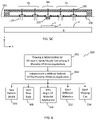
- FIG. 6 is a flow diagram illustrating a method of controlling application of at least one material to a substrate with embedded shaping gas according to the teachings of the present disclosure.
- the present disclosure provides a variety of devices, methods, and systems for controlling the application of paint to automotive vehicles in a high production environment, which reduce overspray and increase transfer efficiency of the paint.
- automotive vehicles is merely exemplary and that other objects that are painted, such as industrial equipment and appliances, among others, may also be painted in accordance with the teachings of the present disclosure.
- the use of “paint” or “painting” should not be construed as limiting the present disclosure, and thus other materials such as coatings, primers, sealants, cleaning solvents, among others, are to be understood as falling within the scope of the present disclosure.
- the teachings of the present disclosure are based on a droplet spray generation device in which a perforate membrane is driven by a piezoelectric transducer.
- This device and variations thereof are described in U.S. Pat. Nos. 6,394,363, 7,550,897, 7,977,849, 8,317,299, 8,191,982, 9,156,049, 7,976,135, 9,452,442, and U.S. Published Application Nos. 2014/0110500, 2016/0228902, and 2016/0158789, which are incorporated herein by reference in their entirety.
- a material source 8 (e.g., a paint source) is included and includes at least one material M (materials M 1 , M 2 , M 3 , . . . M n shown in FIG. 1 ; also referred to herein simply as “material M” or “materials Ms”).
- the material M includes different paint materials, different adhesive materials, different sealant materials, and the like.
- the arm 4 moves according to xyz coordinates with respect to rack 5 such that the material applicator 10 moves across a surface (not labeled) of the part P.
- a power source 6 is configured to supply power to arm 4 and rack 5 .
- Arm 4 and rack 5 are configured to supply material M from the material source 8 to the material applicator 10 such that a coating is applied to the surface of the part P.
- FIG. 1 schematically depicts the paint spray system 2 having a single robotic arm 4 , it should be understood that paint spray systems with more than one robotic arm 4 are included within the teachings of the present disclosure.
- the material applicator 10 includes an array plate 100 with an applicator array 102 comprising a plurality of micro-applicators 110 .
- the array plate 100 lies on single plane. In other aspects of the present disclosure, the array plate 100 does not lie on a single plane as discussed in greater detail below.
- the array plate 100 with the applicator array 102 is positioned within a housing 140 .
- Each of the micro-applicators 110 comprises a plurality of apertures 112 through which a material M is ejected such that atomized droplets 3 of the material M are provided as schematically depicted in FIG. 2B .
- each of the micro-applicators 110 has a micro-applicator plate 114 with the plurality of apertures 112 extending through the micro-applicator plate 114 .
- each of the micro-applicators 110 may include a transducer 120 , a frame 130 and a material inlet 138 .
- the transducer 120 is in mechanical communication with the micro-applicator plate 114 such that activation of the transducer 120 ultrasonically vibrates the micro-applicator plate 114 as schematically depicted by the horizontal (z-direction) double-headed arrows in FIG. 2B .
- the frame 130 includes a back wall 134 and at least one sidewall 132 such that a reservoir 136 for containing the material M is provided between the back wall 134 and the micro-applicator plate 114 .
- the inlet 138 is in fluid communication with reservoir 136 and the material source 8 ( FIG. 1 ) such that the material M can flow from the material source 8 , through inlet 138 and into reservoir 136 .
- the atomized droplets 3 have an average droplet diameter between 5 micrometers ( ⁇ m) and 100 ⁇ m, for example between 10 ⁇ m and 75 ⁇ m, between 10 ⁇ m and 50 ⁇ m, or between 20 ⁇ m and 40 ⁇ m.
- the atomized droplets 3 travel or propagate in a direction generally normal to the micro-applicator plate 114 , i.e., generally parallel to a micro-applicator axis ‘A’.
- a stream ‘S’ of atomized droplets 3 is provided by each of the plurality of apertures 112 and a coating C on the surface(s) s′ of a substrate S is provided. While FIG.
- FIG. 2B schematically depicts the stream S of atomized droplets 3 propagating on the micro-applicator axis A
- the atomized droplets 3 propagate diffusely from the plurality of apertures 112 and the stream S may be angled relative to the micro-applicator axis A.
- other flow configurations of the material M flowing into and out of the reservoir 136 are included in the teachings of the present disclosure in addition to material M entering reservoir 136 through inlet 138 and exiting reservoir 136 through apertures 112 .
- FIG. 2C schematically depicts three subsets of micro-applicators 110 : subset 150 1 , subset 150 2 , and subset 150 3 .
- the subset 150 1 includes the three middle micro-applicators 110 shown in FIG.
- the subset 150 2 includes the two outer micro-applicators 110
- the subset 150 3 includes the three micro-applicators 110 on the right hand side (+x-direction) of the array plate 100 .
- one subset of micro-applicators e.g., subset 150 3
- a subset of the micro-applicators may contain only one micro-applicator 110 .
- each of the micro-applicators can be a subset and thereby by individually addressable.
- a controller 122 ( FIG. 2A ) is included and enabled to individually address the at least one subset of micro-applicators 110 in the applicator array 102 .
- each of the micro-applicators 110 has a supply line 160 ( FIG. 2C ) in fluid communication with its reservoir 136 and the material source 8 .
- the controller 122 is configured to communicate with (i.e. address, receive, and send data) the power source 6 , material source 8 and the at least one subset of micro-applicators 110 such that the at least one subset of micro-applicators 110 is individually addressable (e.g., switched on/off) at any given time.
- controller 122 can individually address the at least one subset of micro-applicators 110 , different materials may be sprayed on the surface s′ from each applicator array 102 . That is, the controller 122 can be configured to control which material M flows into the reservoir(s) of the at least one subset of micro-applicators 110 at any given time such that a coating C comprising a range of thickness, color, rheology, and the like on the surface s′ of the substrate S is provided. For example, the coating C in FIG.
- a first coating or first layer I 1 of the coating C may be formed from a first material M 1 on the substrate S using a first subset of micro-applicators (e.g., subset 150 1 ) and a second coating or second layer I 2 of the coating C may be formed from a second material M 2 over the first coating I 1 using a second subset of micro-applicators (e.g., subset 150 2 ).
- the second coating 12 is applied or formed on the first coating I 1 before the first coating I 1 is fully cured.
- the plurality of micro-applicators 110 can move across the surface S (x and/or y directions) such that the first and second coatings I 1 , I 2 can be formed continuously across the surface s′ of the substrate S using only a subset of micro-applicators 110 . This versatility decreases the consumption of material, energy, etc., of the paint spray system 2 over other high volume production environment paint systems.
- FIGS. 2A through 2C schematically depict the micro-applicators 110 positioned on the single plane 152
- FIGS. 3A through 3C schematically depict the micro-applicators positioned on different geometric planes (referred to herein simply as “plane” or “planes”).
- the array plate 100 has two planes 152 1 and 152 2 arranged parallel but not coplanar to each other.
- One subset 150 4 of the micro-applicators 110 is positioned and aligned on the plane 152 1 and another subset 150 5 of the micro-applicators 110 is positioned and aligned on the plane 152 2 .
- array plate 100 is faceted and has a stepped configuration.
- the two planes 152 1 , 152 2 of the array plate 100 are arranged non-parallel and nonplanar to each other.
- One subset 150 4 of the micro-applicators 110 is positioned and aligned on the plane 152 1 and another subset 150 5 of the micro-applicators 110 is positioned and aligned on the plane 152 2 .
- array plate 100 is faceted and has an angled configuration with the angle not equal to zero degrees.
- planes 152 1 and 152 2 schematically depicted in FIG. 3C are convexly angled with respect to each other, it should be understood that planes concavely angled with respect to each other are within the teachings of the present disclosure. Also, in some forms of the present disclosure the array plate 100 is curved (concave or convex).
- a method 200 of controlling application of material(s) to a substrate includes flowing a material into an ultrasonic spray nozzle comprising a plurality of micro-applicators at step 202 and independently addressing a subset of the plurality of micro-applicators at step 204 .
- Independently addressing the subset of micro-applicators may include varying a pattern width of atomized droplets ejected from the plurality of micro-applicators at step 206 ; varying a flow rate of atomized droplets ejected from the plurality of micro-applicators at step 208 ; varying an angle that the atomized droplets are applied to a surface at step 210 ; ejecting different materials (e.g., M 1 , M 2 , M 3 , or M n shown in FIG. 1 ) at step 212 , and combinations thereof.
- different materials e.g., M 1 , M 2 , M 3 , or M n shown in FIG. 1
- Non-limiting examples of materials ejected at step 212 include paint materials with different colors/pigments shown at 214 , materials for different coating types (e.g., paint, sealant, adhesive, etc.) shown at 216 , different materials for a given coating type (e.g., a paint basecoat material and a paint clearcoat material) shown at 218 ; and combinations thereof.
- materials for different coating types e.g., paint, sealant, adhesive, etc.
- a given coating type e.g., a paint basecoat material and a paint clearcoat material
- the material applicator 12 includes the array plate 100 with the applicator array 102 comprising a plurality of micro-applicators 110 .
- the array plate 100 with the applicator array 102 is positioned within the housing 140 and each of the micro-applicators 110 comprises the plurality of apertures 112 through which a material M (e.g., a fluid or liquid) can be ejected such that a stream S of atomized droplets 3 of the material are provided as schematically depicted in FIG. 2B .
- a material M e.g., a fluid or liquid
- a subset of the plurality of micro-applicators 110 are configured for at least one gas “G” to flow through and assist the flow of the material M from the array plate 100 to the substrate S. It should be understood that such assistance in the flow of the material M with the flow of the gas G is known as “shaping” the flow of the material M and the gas G is known as “shaping gas.”
- shaping gas G include air, nitrogen, and mixtures thereof, among others.
- a subset of micro-applicators labeled ‘ 5 B’ provide shaping gas G on a right side (+x direction) of the array plate 100 such that the coating C on the surface s′ of the substrate S is provided with a sharp or clean edge ‘E’. That is, the shaping gas G flowing through the subset of micro-applicators 110 , labeled ‘Gs’ in FIG. 5B , “shapes” the material M flowing through the subset of micro-applicators 110 labeled ‘Ms’ in FIG. 5B such that the flow of material M is controlled (or limited) in the x-direction shown in the figure and clean edge E is formed.
- shape refers to controlling, directing and/or assisting the flow of the material from a subset of micro-applicators to a substrate such that a desired shape, width, edge, and/or other dimension of a coating C is provided.
- cleaning edge refers to an edge of a coating of material that varies less than 5 millimeters (mm) from a desired line (edge) over a length of the desired line equal to 5 mm.
- the subset of micro-applicators 5 B provide shaping gas G on a right side (+x direction) of the array plate 100 such that the coating C on the surface s′ of the substrate S is provided with a clean edge E that varies less than 4 mm, for example, less than 3 mm or less than 2 mm, a from a desired line (edge) over a length of the desired line equal to 5 mm.
- a subset of micro-applicators labeled ‘ 5 C’ provide material M such that the material M flows through a central portion of the material applicator 12 and is surrounded or shaped by shaping gas G such that a narrow spray of material is ejected from the material applicator 12 , and a narrow (x-direction) coating on the surface s′ is provided with a clean edge ‘E’. That is, the shaping gas G flowing through the subset of micro-applicators 110 labeled ‘Gs’ in FIG. 5C “shapes” the material M flowing through the subset of micro-applicators 110 labeled ‘Ms’ such that the flow of material M is controlled and the width (x-direction) and/or edge E of the coating C is controlled.
- material M flows through the inlet 138 into the reservoirs 136 of the Ms subset of micro-applicators 110 .
- Surface tension of material M results in material M not flowing through the apertures 112 of the micro-applicator plate 114 unless transducer 120 is activated and vibrates as schematically depicted in FIG. 2B . That is, when transducer 120 is activated and vibrates, material M is ejected through and/or from the plurality of apertures 112 as atomized droplets 3 .
- shaping gas G is provided and flows through the inlet 138 and into the reservoirs 136 of the Gs subset of micro-applicators 110 .
- the shaping gas G flows through the plurality of apertures 112 with or without activation of transducer 120 . Accordingly, in some variations of the present disclosure, micro-applicators 110 within a Gs subset of micro-applicators 110 do not have a transducer 120 . Also, the flow, flow rate and/or pressure of the shaping gas G is controlled using a gate valve(s), solenoid valve(s), solenoid switch(es), among others. In at least one variation, the shaping gas has a pressure up to 45 pounds per square inch.
- the controller 122 is included and enabled to individually address the Ms subset of micro-applicators 110 and/or Gs subset of micro-applicators 110 .
- each of the micro-applicators 110 has the supply line 160 ( FIG. 2C ) in fluid communication with its reservoir 136 and the material source 8 or a shaping gas source (not labeled).
- the controller 122 is configured to communicate with (i.e. address, receive, and send data) the power source 6 , material source 8 , shaping gas source, and the Ms and Gs subsets of micro-applicators 110 such that the Ms and Gs subsets of micro-applicators 110 are individually addressable (e.g., switched on/off) at any given time.
- the controller 122 is configured to communicate with (i.e. address, receive, and send data) the power source 6 , material source 8 , shaping gas source, and the Ms and Gs subsets of micro-applicators 110 such that each of the micro-applicators 110 in the Ms and/or Gs subsets of micro-applicators 110 is individually addressable.
- the micro-applicators 110 in the Ms subset of micro-applicators 110 is configured to alternate (i.e., switch), and does alternate, from flowing the material M therethrough to flowing the shaping gas G therethrough.
- At least one of the micro-applicators 110 in the Gs subset of micro-applicators 110 is configured to alternate, and does alternate, from flowing the material shaping gas G therethrough to flowing the material M therethrough.
- This versatility decreases the consumption of material, energy, among others, and increase control of the paint spray system 2 over other high volume production environment paint systems.
- a method 300 of controlling application of material(s) to a substrate includes flowing a material and a shaping gas into an ultrasonic spray nozzle comprising a plurality of micro-applicators at step 302 and independently addressing subsets of the plurality of micro-applicators at step 304 .
- Independently addressing the subsets of micro-applicators may include varying a pattern width of atomized droplets ejected from the Ms subset of micro-applicators at step 306 ; varying a flow rate of atomized droplets ejected from the Ms subset of micro-applicators at step 308 ; varying an angle that the atomized droplets are applied to a surface at step 310 ; ejecting different materials (e.g., M 1 , M 2 , M 3 , or M n shown in FIG. 1 ) at step 312 , ejecting shaping gas through the Gs subset of micro-applicators 110 , and combinations thereof.
- different materials e.g., M 1 , M 2 , M 3 , or M n shown in FIG. 1
- the method includes configuring a subset of an array of micro-applicators to eject a different material than the remainder of the micro-applicators.
- the different material may be a paint basecoat, paint a clearcoat, a flake containing basecoat, a non-flake containing basecoat, a shaping gas, and the like.
- the methods may include configuring a first subset of micro-applicators through which a first material is ejected and configuring a second subset of micro-applicators through which a second material (e.g., a shaping gas) is ejected.
- the first material may be ejected and applied onto a sag prone area of a vehicle followed by ejecting and applying the second material onto the sag prone area of the vehicle.
- the first material is a one-component ( 1 K) material and the second material is a rheology control agent.
- the rheology control agent may be an increased viscosity material or a catalyst material. Coupling the rheology control agent with the 1 K material forms a two-component ( 2 K) material that improves overall appearance and sag control of the 2 K material on the sag prone area of the vehicle.
- the controller is enabled to individually address at least a subset of the micro-applicators.
- a plurality of micro-applicators through manual or automated control are configured and enabled to control (on/off/intensity): flow rate of material, material to be applied, number of materials, pattern width, other coating/painting variables, and combinations thereof. It should be understood that controlling material flow rate ejected from the plurality of micro-applicators controls droplet density and controlling density based as a function of part geometry enables uniform coverage and improves efficiency.
- the present disclosure enables individually addressable micro-applicators and individually addressable arrays or subsets of arrays of micro-applicators.
- the individually addressable micro-applicators enable ejecting two or more different narrowly distributed atomized droplet sizes.
- each micro-applicator and/or each subset of micro-applicators of a material applicator can eject a different material with its required or optimal atomized droplet size.
- a first subset of micro-applicators of a material applicator applies (e.g., sprays) a basecoat material without metallic flake to a first area of a substrate and a second subset of micro-applicators of the material applicator applies a basecoat material with metallic flake to a second area of the substrate.
- the first subset of micro-applicators ejects the basecoat material without metallic flake as atomized droplets with a first narrowly distributed droplet size
- the second subset of micro-applicators ejects the basecoat material with metallic flake as atomized droplets with a second narrowly distributed droplet size that is different than the first average droplet size.
- the phrase “narrowly distributed droplet size” refers to a droplet size distribution where greater than 90% of atomized droplets ejected from a micro-applicator have a droplet diameter within +/ ⁇ 10% of a mean droplet size of the atomized droplets ejected from the micro-applicator.
- the droplet size distribution comprises greater than 95% of atomized droplets ejected from a micro-applicator having a droplet diameter within +/ ⁇ 5% of a mean droplet size.
- a first subset of micro-applicators of a material applicator applies a first color material to a first area of a substrate and a second subset of micro-applicators of the material applicator applies a second color material to a second area of the substrate.
- the first subset of micro-applicators ejects the first color material as atomized droplets with a first average droplet size and the second subset of micro-applicators ejects the second color material as atomized droplets with a second average droplet size that is different than the first average droplet size.
- a first subset of micro-applicators of a material applicator applies a first layer material to a substrate and a second subset of micro-applicators of the material applicator applies a second layer material over the first layer material on the substrate.
- the first subset of micro-applicators ejects the first layer material as atomized droplets with a first average droplet size and the second subset of micro-applicators ejects the second layer material as atomized droplets with a second average droplet size that is different than the first average droplet size.
- a first subset of micro-applicators of a material applicator applies a paint material to a first area of a substrate and a second subset of micro-applicators of the material applicator applies a shaping gas to control or shape the flow of the paint material from the first subset of micro-applicators to the substrate.
- a paint booth using the composite ultrasonic applicators disclosed herein may provide improved efficiency and reduced cost.
- a paint booth may have:
- the phrase at least one of A, B, and C should be construed to mean a logical (A OR B OR C), using a non-exclusive logical OR, and should not be construed to mean “at least one of A, at least one of B, and at least one of C.”
- first, second, third, etc. may be used to describe various elements, components, regions, layers and/or sections, these elements, components, regions, layers and/or sections, should not be limited by these terms. These terms may be only used to distinguish one element, component, region, layer and/or section, from another element, component, region, layer and/or section. Terms such as “first,” “second,” and other numerical terms when used herein do not imply a sequence or order unless clearly indicated by the context. Thus, a first element, component, region, layer or section, could be termed a second element, component, region, layer or section without departing from the teachings of the example forms. Furthermore, an element, component, region, layer or section may be termed a “second” element, component, region, layer or section, without the need for an element, component, region, layer or section termed a “first” element, component, region, layer or section.
- Spacially relative terms such as “outer,” “below,” “lower,” and the like, may be used herein for ease of description to describe one element or feature's relationship to another element(s) or feature(s) as illustrated in the figures. Spatially relative terms may be intended to encompass different orientations of the device in use or operation in addition to the orientation depicted in the figures. For example, if the device in the figures is turned over, elements described as “below” or “beneath” other elements or features would then be oriented “above” the other elements or features. Thus, the example term “below” can encompass both an orientation of above or below. The device may be otherwise oriented (rotated 90 degrees or at other orientations) and the spatially relative descriptors used herein interpreted accordingly.
Landscapes
- Application Of Or Painting With Fluid Materials (AREA)
Abstract
Description
-
- airflow reduced from ˜100 ft/min. down to 60 ft/min.;
- a side-draft booth in automated zones thereby providing a smaller footprint for the paint booth;
- reductions in dry-booth material consumption and a reduction or elimination of wet-booth sludge system;
- recirculation of air limited only by LEL (lower explosive level) of solvent;
- reduction of high pressure water blasting/cleaning of booth grates;
- reduced air consumption and associated reduction in energy used to heat, humidify, and condition booth air;
- reduced air consumption allowing reductions in abatement equipment size; and
- reduction in sludge waste removal and landfill cost.
Claims (20)
Priority Applications (2)
| Application Number | Priority Date | Filing Date | Title |
|---|---|---|---|
| US17/020,394 US11413643B2 (en) | 2018-01-30 | 2020-09-14 | Composite ultrasonic material applicators with embedded shaping gas micro-applicators and methods of use thereof |
| US17/862,722 US11872580B2 (en) | 2018-01-30 | 2022-07-12 | Composite ultrasonic material applicators with embedded shaping gas micro-applicators and methods of use thereof |
Applications Claiming Priority (3)
| Application Number | Priority Date | Filing Date | Title |
|---|---|---|---|
| US201862624013P | 2018-01-30 | 2018-01-30 | |
| US16/211,554 US10940501B2 (en) | 2018-01-30 | 2018-12-06 | Composite ultrasonic material applicators with individually addressable micro-applicators and methods of use thereof |
| US17/020,394 US11413643B2 (en) | 2018-01-30 | 2020-09-14 | Composite ultrasonic material applicators with embedded shaping gas micro-applicators and methods of use thereof |
Related Parent Applications (1)
| Application Number | Title | Priority Date | Filing Date |
|---|---|---|---|
| US16/211,554 Continuation-In-Part US10940501B2 (en) | 2018-01-30 | 2018-12-06 | Composite ultrasonic material applicators with individually addressable micro-applicators and methods of use thereof |
Related Child Applications (1)
| Application Number | Title | Priority Date | Filing Date |
|---|---|---|---|
| US17/862,722 Division US11872580B2 (en) | 2018-01-30 | 2022-07-12 | Composite ultrasonic material applicators with embedded shaping gas micro-applicators and methods of use thereof |
Publications (2)
| Publication Number | Publication Date |
|---|---|
| US20210001369A1 US20210001369A1 (en) | 2021-01-07 |
| US11413643B2 true US11413643B2 (en) | 2022-08-16 |
Family
ID=74066263
Family Applications (1)
| Application Number | Title | Priority Date | Filing Date |
|---|---|---|---|
| US17/020,394 Active US11413643B2 (en) | 2018-01-30 | 2020-09-14 | Composite ultrasonic material applicators with embedded shaping gas micro-applicators and methods of use thereof |
Country Status (1)
| Country | Link |
|---|---|
| US (1) | US11413643B2 (en) |
Families Citing this family (2)
| Publication number | Priority date | Publication date | Assignee | Title |
|---|---|---|---|---|
| KR102534771B1 (en) * | 2021-12-13 | 2023-05-26 | 주식회사 그린온 | Vaporizer for Sterilization and Deinsectization |
| US20250170609A1 (en) * | 2023-11-29 | 2025-05-29 | Ford Global Technologies, Llc | Method and apparatus for coating a substrate |
Citations (3)
| Publication number | Priority date | Publication date | Assignee | Title |
|---|---|---|---|---|
| US7975938B2 (en) * | 2003-03-28 | 2011-07-12 | Ultrasonic Systems, Inc. | Coating system |
| US9592524B2 (en) * | 2010-05-06 | 2017-03-14 | Duerr Systems Gmbh | Coating device comprising a jet of coating medium which is broken down into drops |
| US20190232322A1 (en) * | 2018-01-30 | 2019-08-01 | Ford Motor Company | Composite ultrasonic material applicators with individually addressable micro-applicators and methods of use thereof |
-
2020
- 2020-09-14 US US17/020,394 patent/US11413643B2/en active Active
Patent Citations (4)
| Publication number | Priority date | Publication date | Assignee | Title |
|---|---|---|---|---|
| US7975938B2 (en) * | 2003-03-28 | 2011-07-12 | Ultrasonic Systems, Inc. | Coating system |
| US9592524B2 (en) * | 2010-05-06 | 2017-03-14 | Duerr Systems Gmbh | Coating device comprising a jet of coating medium which is broken down into drops |
| US20190232322A1 (en) * | 2018-01-30 | 2019-08-01 | Ford Motor Company | Composite ultrasonic material applicators with individually addressable micro-applicators and methods of use thereof |
| US10940501B2 (en) * | 2018-01-30 | 2021-03-09 | Ford Motor Company | Composite ultrasonic material applicators with individually addressable micro-applicators and methods of use thereof |
Also Published As
| Publication number | Publication date |
|---|---|
| US20210001369A1 (en) | 2021-01-07 |
Similar Documents
| Publication | Publication Date | Title |
|---|---|---|
| US12005463B2 (en) | Composite ultrasonic material applicators with individually addressable micro-applicators and methods of use thereof | |
| JP6231596B2 (en) | Coating equipment and coating equipment coating equipment | |
| JP2017185491A (en) | Spray coating equipment and system | |
| CN108212574A (en) | The coating head of coating and the coating system including coating head are coated on surface to be coated | |
| US11413643B2 (en) | Composite ultrasonic material applicators with embedded shaping gas micro-applicators and methods of use thereof | |
| RU2009123467A (en) | METHOD OF OPERATION OF THE SPRAYER AND THE APPROPRIATE DEVICE FOR APPLICATION OF THE COATING | |
| CN115921192A (en) | Ultrasonic atomizer for applying coatings to substrates | |
| US11872580B2 (en) | Composite ultrasonic material applicators with embedded shaping gas micro-applicators and methods of use thereof | |
| US12589405B2 (en) | Ultrasonic atomizer with acoustic focusing device | |
| US20220314263A1 (en) | Reversible nozzle in ultrasonic atomizer for clog prevention | |
| CN110252543B (en) | Air forming cover, rotary cup and atomization spraying device | |
| WO2007000853A1 (en) | Bell type coating device | |
| JP5474638B2 (en) | Electrostatic coating method | |
| JPH0222051Y2 (en) | ||
| JP2001046948A (en) | Formation of strippable film | |
| CN120054839A (en) | Method and apparatus for coating a substrate | |
| JPH10113602A (en) | Spray coating method | |
| JPH0631236A (en) | Electrostatic coating method for metallic paint | |
| JPH0474061B2 (en) |
Legal Events
| Date | Code | Title | Description |
|---|---|---|---|
| FEPP | Fee payment procedure |
Free format text: ENTITY STATUS SET TO UNDISCOUNTED (ORIGINAL EVENT CODE: BIG.); ENTITY STATUS OF PATENT OWNER: LARGE ENTITY |
|
| STPP | Information on status: patent application and granting procedure in general |
Free format text: APPLICATION DISPATCHED FROM PREEXAM, NOT YET DOCKETED |
|
| AS | Assignment |
Owner name: FORD MOTOR COMPANY, MICHIGAN Free format text: ASSIGNMENT OF ASSIGNORS INTEREST;ASSIGNORS:SEUBERT, CHRISTOPHER MICHAEL;LIU, WANJIAO;ELLWOOD, KEVIN RICHARD JOHN;AND OTHERS;SIGNING DATES FROM 20200831 TO 20200901;REEL/FRAME:054932/0102 |
|
| STPP | Information on status: patent application and granting procedure in general |
Free format text: NON FINAL ACTION MAILED |
|
| STPP | Information on status: patent application and granting procedure in general |
Free format text: NON FINAL ACTION MAILED |
|
| STPP | Information on status: patent application and granting procedure in general |
Free format text: RESPONSE TO NON-FINAL OFFICE ACTION ENTERED AND FORWARDED TO EXAMINER |
|
| STPP | Information on status: patent application and granting procedure in general |
Free format text: FINAL REJECTION MAILED |
|
| STPP | Information on status: patent application and granting procedure in general |
Free format text: RESPONSE AFTER FINAL ACTION FORWARDED TO EXAMINER |
|
| STPP | Information on status: patent application and granting procedure in general |
Free format text: NOTICE OF ALLOWANCE MAILED -- APPLICATION RECEIVED IN OFFICE OF PUBLICATIONS |
|
| STPP | Information on status: patent application and granting procedure in general |
Free format text: PUBLICATIONS -- ISSUE FEE PAYMENT VERIFIED |
|
| STCF | Information on status: patent grant |
Free format text: PATENTED CASE |
|
| MAFP | Maintenance fee payment |
Free format text: PAYMENT OF MAINTENANCE FEE, 4TH YEAR, LARGE ENTITY (ORIGINAL EVENT CODE: M1551); ENTITY STATUS OF PATENT OWNER: LARGE ENTITY Year of fee payment: 4 |