JP2017185491A - Spray coating device and system - Google Patents
Spray coating device and system Download PDFInfo
- Publication number
- JP2017185491A JP2017185491A JP2017116978A JP2017116978A JP2017185491A JP 2017185491 A JP2017185491 A JP 2017185491A JP 2017116978 A JP2017116978 A JP 2017116978A JP 2017116978 A JP2017116978 A JP 2017116978A JP 2017185491 A JP2017185491 A JP 2017185491A
- Authority
- JP
- Japan
- Prior art keywords
- air
- spray
- central axis
- liquid
- shaping
- Prior art date
- Legal status (The legal status is an assumption and is not a legal conclusion. Google has not performed a legal analysis and makes no representation as to the accuracy of the status listed.)
- Granted
Links
- 238000005507 spraying Methods 0.000 title claims abstract description 74
- 238000007493 shaping process Methods 0.000 claims abstract description 65
- 239000007788 liquid Substances 0.000 claims abstract description 64
- 230000001154 acute effect Effects 0.000 claims abstract description 13
- 239000007921 spray Substances 0.000 claims description 144
- 239000007787 solid Substances 0.000 claims description 11
- 238000004891 communication Methods 0.000 claims description 7
- 238000011144 upstream manufacturing Methods 0.000 claims description 5
- 238000007592 spray painting technique Methods 0.000 claims 1
- 239000011248 coating agent Substances 0.000 abstract description 26
- 238000000576 coating method Methods 0.000 abstract description 26
- 238000000889 atomisation Methods 0.000 abstract description 15
- 239000012530 fluid Substances 0.000 description 126
- 238000000034 method Methods 0.000 description 16
- 238000009826 distribution Methods 0.000 description 15
- 238000010422 painting Methods 0.000 description 14
- 230000008569 process Effects 0.000 description 12
- 239000003973 paint Substances 0.000 description 10
- 230000008901 benefit Effects 0.000 description 7
- 230000000694 effects Effects 0.000 description 7
- 239000002245 particle Substances 0.000 description 6
- 238000013459 approach Methods 0.000 description 5
- 238000009718 spray deposition Methods 0.000 description 5
- 230000000712 assembly Effects 0.000 description 4
- 238000000429 assembly Methods 0.000 description 4
- 230000007423 decrease Effects 0.000 description 4
- 230000007246 mechanism Effects 0.000 description 4
- 238000012360 testing method Methods 0.000 description 4
- 239000002699 waste material Substances 0.000 description 4
- 238000011161 development Methods 0.000 description 3
- 241000722921 Tulipa gesneriana Species 0.000 description 2
- 238000007664 blowing Methods 0.000 description 2
- 238000013461 design Methods 0.000 description 2
- 238000010586 diagram Methods 0.000 description 2
- 239000000975 dye Substances 0.000 description 2
- 238000003912 environmental pollution Methods 0.000 description 2
- 230000004907 flux Effects 0.000 description 2
- 238000005259 measurement Methods 0.000 description 2
- 238000012986 modification Methods 0.000 description 2
- 230000004048 modification Effects 0.000 description 2
- 238000012856 packing Methods 0.000 description 2
- 238000003860 storage Methods 0.000 description 2
- 230000009471 action Effects 0.000 description 1
- 230000015572 biosynthetic process Effects 0.000 description 1
- 230000008859 change Effects 0.000 description 1
- -1 clear coats Substances 0.000 description 1
- 238000011109 contamination Methods 0.000 description 1
- 238000001723 curing Methods 0.000 description 1
- 238000001035 drying Methods 0.000 description 1
- 238000005516 engineering process Methods 0.000 description 1
- 239000002360 explosive Substances 0.000 description 1
- 230000006870 function Effects 0.000 description 1
- 238000011416 infrared curing Methods 0.000 description 1
- 230000003993 interaction Effects 0.000 description 1
- 238000004519 manufacturing process Methods 0.000 description 1
- 239000000463 material Substances 0.000 description 1
- 238000002156 mixing Methods 0.000 description 1
- 230000003287 optical effect Effects 0.000 description 1
- 230000009467 reduction Effects 0.000 description 1
- 239000000758 substrate Substances 0.000 description 1
- 238000010998 test method Methods 0.000 description 1
- 230000005514 two-phase flow Effects 0.000 description 1
- 238000009827 uniform distribution Methods 0.000 description 1
Images


Classifications
-
- B—PERFORMING OPERATIONS; TRANSPORTING
- B05—SPRAYING OR ATOMISING IN GENERAL; APPLYING FLUENT MATERIALS TO SURFACES, IN GENERAL
- B05B—SPRAYING APPARATUS; ATOMISING APPARATUS; NOZZLES
- B05B7/00—Spraying apparatus for discharge of liquids or other fluent materials from two or more sources, e.g. of liquid and air, of powder and gas
- B05B7/02—Spray pistols; Apparatus for discharge
- B05B7/08—Spray pistols; Apparatus for discharge with separate outlet orifices, e.g. to form parallel jets, i.e. the axis of the jets being parallel, to form intersecting jets, i.e. the axis of the jets converging but not necessarily intersecting at a point
- B05B7/0807—Spray pistols; Apparatus for discharge with separate outlet orifices, e.g. to form parallel jets, i.e. the axis of the jets being parallel, to form intersecting jets, i.e. the axis of the jets converging but not necessarily intersecting at a point to form intersecting jets
- B05B7/0815—Spray pistols; Apparatus for discharge with separate outlet orifices, e.g. to form parallel jets, i.e. the axis of the jets being parallel, to form intersecting jets, i.e. the axis of the jets converging but not necessarily intersecting at a point to form intersecting jets with at least one gas jet intersecting a jet constituted by a liquid or a mixture containing a liquid for controlling the shape of the latter
-
- B—PERFORMING OPERATIONS; TRANSPORTING
- B05—SPRAYING OR ATOMISING IN GENERAL; APPLYING FLUENT MATERIALS TO SURFACES, IN GENERAL
- B05B—SPRAYING APPARATUS; ATOMISING APPARATUS; NOZZLES
- B05B7/00—Spraying apparatus for discharge of liquids or other fluent materials from two or more sources, e.g. of liquid and air, of powder and gas
- B05B7/02—Spray pistols; Apparatus for discharge
- B05B7/06—Spray pistols; Apparatus for discharge with at least one outlet orifice surrounding another approximately in the same plane
- B05B7/062—Spray pistols; Apparatus for discharge with at least one outlet orifice surrounding another approximately in the same plane with only one liquid outlet and at least one gas outlet
- B05B7/066—Spray pistols; Apparatus for discharge with at least one outlet orifice surrounding another approximately in the same plane with only one liquid outlet and at least one gas outlet with an inner liquid outlet surrounded by at least one annular gas outlet
-
- B—PERFORMING OPERATIONS; TRANSPORTING
- B05—SPRAYING OR ATOMISING IN GENERAL; APPLYING FLUENT MATERIALS TO SURFACES, IN GENERAL
- B05B—SPRAYING APPARATUS; ATOMISING APPARATUS; NOZZLES
- B05B7/00—Spraying apparatus for discharge of liquids or other fluent materials from two or more sources, e.g. of liquid and air, of powder and gas
- B05B7/02—Spray pistols; Apparatus for discharge
- B05B7/12—Spray pistols; Apparatus for discharge designed to control volume of flow, e.g. with adjustable passages
- B05B7/1209—Spray pistols; Apparatus for discharge designed to control volume of flow, e.g. with adjustable passages the controlling means for each liquid or other fluent material being manual and interdependent
-
- Y—GENERAL TAGGING OF NEW TECHNOLOGICAL DEVELOPMENTS; GENERAL TAGGING OF CROSS-SECTIONAL TECHNOLOGIES SPANNING OVER SEVERAL SECTIONS OF THE IPC; TECHNICAL SUBJECTS COVERED BY FORMER USPC CROSS-REFERENCE ART COLLECTIONS [XRACs] AND DIGESTS
- Y10—TECHNICAL SUBJECTS COVERED BY FORMER USPC
- Y10S—TECHNICAL SUBJECTS COVERED BY FORMER USPC CROSS-REFERENCE ART COLLECTIONS [XRACs] AND DIGESTS
- Y10S239/00—Fluid sprinkling, spraying, and diffusing
- Y10S239/14—Paint sprayers
Abstract
Description
本発明は、一般的に吹付システムに関し、詳細には塗料や染料等の被覆剤を塗布するための工業用吹付塗装システムに関する。特に、本発明は、塗装流体の霧化および噴霧パターンを改善する独特の噴霧整形上の特徴を有したエアキャップに関する。 The present invention relates generally to spray systems, and more particularly to industrial spray coating systems for applying coatings such as paints and dyes. In particular, the present invention relates to air caps with unique spray shaping features that improve the atomization and spray pattern of the coating fluid.
本項目は、後述する本発明の種々の特徴に関連するさまざまな特徴を説明する。以下の説明は、本発明のさまざまな特徴のより良い理解を容易にする背景情報を提供するのに役立つであろう。従って、以下の説明はこうした文脈で理解されるべきであり、従来技術として容認するものではない。 This section describes various features related to various features of the present invention described below. The following description will serve to provide background information that facilitates a better understanding of the various features of the present invention. Accordingly, the following description should be understood in this context and is not acceptable as prior art.
従来の吹付ガンは、流体オリフィスから供給される柱状またはシート状の流体から小さな液滴を生成する流体霧化プロセスを一般的に採用している。典型的に二相流状態での霧化プロセスは、流体ノズルから流体流れとして高速で流れる液体のエネルギを伴っている。流体流れが、柱状流体の周囲の同一直線上の空気の流れに出会うと、該流体流れは、第1段階の霧化および第2段階の霧化を受ける。第1段階の霧化は、流体ノズル近傍での中実流れとして特徴付けられる。第2段階では、霧化が生じ液滴が形成される。 Conventional spray guns generally employ a fluid atomization process that produces small droplets from columnar or sheet-like fluid supplied from a fluid orifice. The atomization process typically in a two-phase flow involves the energy of a liquid that flows at high speed as a fluid flow from a fluid nozzle. When the fluid flow encounters a collinear air flow around the columnar fluid, the fluid flow undergoes a first stage atomization and a second stage atomization. The first stage atomization is characterized as a solid flow near the fluid nozzle. In the second stage, atomization occurs and droplets are formed.
液滴は、整形空気流れを用いて特定の噴霧パターンに整形される。この噴霧パターンは通常は円錐形状である。その結果、吹付ガンの出口から、該吹付ガンにより塗装すべき目的表面へ向けて噴霧幅および/または断面積が一般的に増加する。すなわち、噴霧の外形または周縁は、一般的に、吹付ガンの中心線に対する角度で特徴付けられる。吹付速度は、また、吹付ガンの出口から遠ざかるにつれ減少する。 The droplets are shaped into a specific spray pattern using a shaped air stream. This spray pattern is usually conical. As a result, the spray width and / or cross-sectional area generally increases from the outlet of the spray gun towards the target surface to be painted by the spray gun. That is, the profile or periphery of the spray is generally characterized by the angle to the spray gun centerline. The spray speed also decreases as you move away from the outlet of the spray gun.
こうして、吹付ガンが目標表面の比較的近傍に配置される場合、噴霧は目標表面の比較的小さな範囲部分を高速でカバーする。カバーする範囲が小さいと、吹付塗装工程を完了するのに要する時間が長くなり、かつ、吹付塗装の均一性が低下する。この近距離において吹付速度が高すぎると、噴霧が目標表面に効果的に輸送されなくなる(つまり輸送効率の低下)。例えば、速度が高いと、目標表面で噴霧が付着せずに跳ね返る。その結果、輸送効率が低下すると、無駄と環境への汚染が増え、目標表面を塗装するためのコストが増加する(つまり、表面を塗装するのに多量の流体が必要となる)。 Thus, when the spray gun is placed relatively close to the target surface, the spray covers a relatively small area of the target surface at high speed. If the range to be covered is small, the time required to complete the spray coating process becomes long, and the uniformity of the spray coating decreases. If the spray speed is too high at this short distance, the spray is not effectively transported to the target surface (that is, the transport efficiency is reduced). For example, when the speed is high, the spray rebounds without adhering to the target surface. As a result, reduced transport efficiency increases waste and environmental pollution and increases the cost of painting the target surface (ie, a large amount of fluid is required to paint the surface).
吹付ガンを目標表面から遠く離して配置すると、噴霧は、目標表面の比較的広い範囲を比較的低速でカバーする。このように遠くから低速で吹付けると、噴霧は効率的に目標表面に輸送されない(つまり、輸送効率が低下する)。同様に、輸送効率が低下すると、無駄と環境への汚染が増加し、目標表面を塗装するためのコストが増加する(つまり、表面を塗装するのに多量の流体が必要となる)。 When the spray gun is placed far away from the target surface, the spray covers a relatively large area of the target surface at a relatively low speed. When sprayed at a low speed from a distance as described above, the spray is not efficiently transported to the target surface (that is, transport efficiency decreases). Similarly, reduced transport efficiency increases waste and environmental pollution and increases the cost of painting the target surface (ie, requiring a large amount of fluid to paint the surface).
その結果、円錐状に噴霧する典型的な吹付ガンは、吹付速度が高すぎず、また低すぎないような、ある距離に配置される。然しながら、この距離は、小さな範囲しかカバーできないので、吹付塗装の均一性が低下し、かつ、目標表面への塗装に必要な時間が長くなる。つまり、速度を最適化すると最適な塗装範囲が得られず、また塗装範囲を最適化すると最適な速度が得られなくなる。一般的な吹付ガンでは、円錐状に噴霧するので、最適な速度および最適な塗装範囲の双方を得ることができない。 As a result, a typical spray gun spraying conically is placed at a distance such that the spray speed is neither too high nor too low. However, since this distance can only cover a small range, the uniformity of spray coating is reduced and the time required for painting on the target surface is lengthened. That is, if the speed is optimized, the optimum coating range cannot be obtained, and if the painting range is optimized, the optimum speed cannot be obtained. A general spray gun sprays in a conical shape, so that it is not possible to obtain both an optimum speed and an optimum coating range.
請求項1に記載の本発明は、液体通路と、空気通路と、前記液体通路を流通する液体の流れおよび前記空気通路を流通する空気の流れを開閉する1または複数の弁と、前記1または複数の弁に結合されたトリガーと、非円錐状の液体噴霧を形成する霧化ヘッドとを具備する吹付塗装装置において、前記霧化ヘッドが、前記液体通路に連通した液体出口であって、液体流れの長手の中心軸線を有した液体出口と、前記液体出口と同軸に配置され、かつ、前記空気通路に連通した空気出口と、対設されたエアホーンに形成され前記空気通路に連通した複数の第1の整形空気オリフィスであって、該第1の整形空気オリフィスは、前記長手の中心軸線に対して所定の第1の鋭角で同長手の中心軸線沿いの第1の位置で収斂する第1の中心軸線を有している複数の第1の整形空気オリフィスと、対設されたエアホーンに形成され前記空気通路に連通した複数の第2の整形空気オリフィスであって、該第2の整形空気オリフィスは、前記長手の中心軸線に対して所定の第2の鋭角で同長手の中心軸線沿いの第2の位置で収斂する第2の中心軸線を有している複数の第2の整形空気オリフィスとを具備し、前記第1と第2の鋭角は互いに異なっており、かつ、前記長手の中心軸線と前記複数の第1と第2の整形空気オリフィスとの間で互いに交差し、前記第1と第2の位置は、前記長手の中心軸線と複数の前記第1と第2の整形空気オリフィスに関して反対の順序で、前記長手の中心軸線沿いに順次配置されており、前記第1と第2の整形オリフィスは中実の整形空気流れを出力し、前記第1の点の下流側に円錐面から外側に膨出する非円錐状の液体噴霧が形成されるようにした吹付塗装装置を要旨とする。
更に、本発明によれば、噴霧装置の噴霧整形素子を具備したシステムにおいて、前記噴霧整形素子が、液体放出中心軸線を有した液体オリフィスと、エアホーンに形成され、前記液体放出中心軸線と交差する第1の中心軸線を有した第1の整形空気オリフィスであって、前記第1の中心軸線が前記液体放出中心軸線沿いの第1の領域へ向けて指向されている第1の整形空気オリフィスと、前記エアホーンに形成され、前記液体放出中心軸線と交差する第2の中心軸線を有した第2の整形空気オリフィスであって、前記第2の中心軸線が前記液体放出中心軸線沿いの第2の領域へ向けて指向されている第2の整形空気オリフィスとを具備し、前記第1の領域が前記液体放出中心軸線沿いに前記第2の領域から下流側にあり、かつ、前記第1の整形空気オリフィスが、前記液体放出中心軸線に関して、前記第2の整形空気オリフィスから上流側にあり、前記第1と第2の整形空気オリフィスが中実の整形空気流れを出力するように形成され、そして、該中実の整形空気流れは、前記液体オリフィスによって非円錐状の噴霧液体出力が生成されるように形成されており、該非円錐状の噴霧は前記第1の領域の下流側で円錐面から外側に膨出しているシステムが提供される。
The present invention described in
Further, according to the present invention, in the system including the spray shaping element of the spray device, the spray shaping element is formed in the liquid orifice having the liquid discharge center axis and the air horn and intersects the liquid discharge center axis. A first shaped air orifice having a first center axis, wherein the first center axis is directed toward a first region along the liquid discharge center axis; A second shaped air orifice formed in the air horn and having a second center axis intersecting the liquid discharge center axis, wherein the second center axis is a second along the liquid discharge center axis. A second shaped air orifice directed toward the region, wherein the first region is downstream from the second region along the liquid discharge center axis, and An air orifice is upstream from the second shaped air orifice with respect to the liquid discharge center axis, and the first and second shaped air orifices are configured to output a solid shaped air flow; and The solid shaped air stream is formed such that a non-conical spray liquid output is generated by the liquid orifice, the non-conical spray being downstream from the first region from a conical surface; An outwardly bulging system is provided.
本発明の上記および他の特徴、利点は、添付図面を参照して説明する以下の実施形態から一層良く理解されよう。添付図面において、同様の部品は同じ参照符号で示されている。 The above and other features and advantages of the present invention will be better understood from the following embodiments described with reference to the accompanying drawings. In the accompanying drawings, like parts are designated by the same reference numerals.
以下、本発明の1または複数の特定の実施形態を説明する。なお、実際の機器の特徴については省略して説明を簡略化する。こうした実際の機器の開発では、他のエンジニアリング作業や設計作業と同様に、例えば、システムに関連した制限や取引に関連した制限のような特定の開発目標を達成するために実装時に固有の多くの決定がなされなければならず、そしてそれは、ある実装形態から他の実装形態で変化するであろう。更に、開発作業は複雑で時間を要するものであるが、この出願の開示から利益を得る当業者にとっては、設計、組立、製造の決められた手順であろう。 The following describes one or more specific embodiments of the present invention. Note that the features of actual devices are omitted to simplify the description. The development of these actual devices, like other engineering and design tasks, includes many of the implementation specific to achieve specific development goals, such as system-related restrictions and transaction-related restrictions. A decision must be made and it will vary from one implementation to another. Furthermore, while the development work is complex and time consuming, for those skilled in the art who would benefit from the disclosure of this application, it would be a fixed procedure for design, assembly and manufacture.
図1は、吹付塗装システム10の一例を示すブロック図であり、該吹付塗装システムは塗装対象物14に所望の被覆剤を塗布するための吹付塗装装置12を具備している。詳細に後述するように、吹付塗装装置12は、塗装対象物14への塗装流体の輸送効率を最適化するようにした独特の噴霧整形上の特徴を有している。例えば、この噴霧整形上の特徴は、流体速度、噴霧範囲(例えば、塗装対象物14上の面積)、流体分布の均一性(例えば、塗装対象物14上の均一な流体の量および色)、流体霧化等を最適化するようになっている。更なる例として、この噴霧整形上の特徴は、非円錐状の噴霧形状および/または装置12の出口から塗装対象物14へ非直線状に(例えば湾曲させて)変化する幅によって特徴付けられる噴霧形状を可能とする。特定の実施形態では、噴霧形状は、カップ形または凹形の輪郭または周縁(例えば外縁)によって特徴付けられ、噴霧形状の幅および/または断面積は、吹付塗装装置12の出口近傍において、円錐状の噴霧よりも大きくなっている。他の実施形態では、噴霧形状は、チューリップ状の輪郭または周縁によって特徴付けられよう。後述するように、前記独特の噴霧整形上の特徴によって、吹付塗装装置12の出口近傍における適切な速度を伴った一層広い塗装範囲を可能とし、以って、輸送効率が改善され、無駄と汚染が低減される。
FIG. 1 is a block diagram showing an example of a
本明細書の文脈において、「円錐」「非円錐」との語は、噴霧形状を説明するために用いられる場合、中実の噴霧形状の周縁部の全体的な形状を意味するものとする。これらの語は、噴霧の周縁部に沿ってのみ液滴が移動することを意味しない。液滴は、実際上、噴霧の内部空間全体に亘って輸送される。 In the context of this specification, the terms “cone” and “non-cone”, when used to describe the spray shape, shall mean the overall shape of the periphery of the solid spray shape. These terms do not imply that the droplets move only along the periphery of the spray. The droplets are actually transported over the entire interior space of the spray.
図示する吹付塗装装置12は、空気式霧化器、回転式霧化器、静電式霧化器その他の適当な噴霧形成機構を具備することができる。吹付塗装装置12は、ハンドル部分、該ハンドル部分に結合された銃身部分または本体部分、1または複数の弁に係合、離脱可能なトリガーを備えたピストル形の吹付ガンが望ましい場合もあろう。然しながら、本願の噴霧整形上の特徴は、どのようなタイプの吹付装置にも利用することができる。
The illustrated
吹付塗装装置12は、流体供給源16、空気供給源18、制御装置20のような種々の供給システムおよび制御システムに結合することができる。制御装置20は、流体供給源16、空気供給源18の制御を容易にし、かつ、吹付塗装装置12による塗装対象物14への許容できる品質の吹付塗装を確実にする。例えば、制御装置20は、自動制御器22、位置決め制御器24、流体供給制御器26、空気供給制御器28、コンピュータシステム30、ユーザインターフェース32を含むことができる。
The
制御装置20は、1または複数の位置決め装置34、36に結合することができる。例えば、位置決め装置34は、吹付塗装装置12に対する塗装対象物14の移動を補助する。位置決め装置36は、吹付塗装装置12に結合されており、吹付塗装装置12が塗装対象物14に対して移動できるようにする。また、システム10は、位置決め装置36に結合された複数の吹付塗装装置12を含むことができ、これによって、塗装対象物14上の塗装範囲が改善される。こうして、吹付塗装システム10は、流体の混合、流体と空気の流量、噴霧パターン/塗装対象物上の塗装範囲をコンピュータ制御する。特定の用途によっては、位置決め装置34、36は、ロボットアーム、コンベアベルトその他の適当な位置決め機構を含むことができる。
The
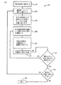
図2は、塗装対象物14へ所望の被覆剤を吹付塗装するための吹付塗装プロセス100の一例を示すフローチャートである。図示するように、プロセス100は、所望の流体を塗布するために塗装対象物14の識別から開始する(ブロック102)。プロセス100は、次いで、塗装対象物の塗装面へ塗装する所望の流体を選択する(ブロック104)。所望の流体には、ベースコート剤、塗料、クリアコート剤、染料等が含まれよう。ユーザは、次いで、塗装対象物14および選択された流体を識別するように吹付塗装装置12を設定する(ブロック106)。塗装対象物14には、自動車、家具、家電製品等が含まれよう。ユーザが吹付塗装装置12を起動すると、プロセス100は、次いで、選択された流体40を霧化し噴霧を形成する(ブロック108)。後述する実施形態では、噴霧は、カップ形、凹形またはチューリップ形といった非円錐形状を有している。ユーザは、次いで、塗装対象物14の所望の表面上に噴霧を塗布する(ブロック110)。プロセス100は、次いで、前記所望表面に塗布された被覆剤の硬化/乾燥(例えば、赤外線硬化ランプ)を行う(ブロック112)。ブロック114において、選択された流体40によって更なる塗装をユーザが望む場合には、プロセス100は、ブロック108、110、112を実行し、選択された流体40で更なる塗装を行う。ブロック114において、選択された流体40によって更なる塗装をユーザが望まない場合には、プロセス100は、ブロック116でユーザが新たな流体での塗装を望むか否かを判断する。ブロック116で、ユーザが新規の流体での塗装を望む場合、プロセス100は、ブロック104〜114を実行し、選択された新たな流体を用いて塗装する。ユーザが新規の流体での塗装を望まない場合、プロセス100はブロック118で終了する。
FIG. 2 is a flowchart showing an example of a
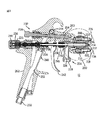
図3は、吹付塗装装置12の1つの例示的実施形態の側断面図である。図示するように、吹付塗装装置12は、本体202に結合された吹付先端組立体200を具備している。吹付先端組立体200は、流体供給先端組立体204を含んでいる。流体供給先端組立体204は、例えば、異なる複数のタイプの吹付塗装装置に装着可能とすることができる。吹付先端組立体200は、また、流体供給先端組立体204に結合された噴霧形成組立体206を含んでいる。噴霧形成組立体206は、保持ナット210によって本体202に着脱自在に固定されるエアキャップ208を具備している。エアキャップ208は、流体供給先端組立体204の流体出口214を中心とする中心環状霧化オリフィス212のような種々の空気霧化オリフィスを有している。エアキャップ208は、また、噴霧整形(エアホーン)オリフィス216、218、220、222のような1または複数の噴霧整形オリフィスを有することができる。該噴霧整形オリフィスは、霧化された流体を所望の噴霧パターン(例えば非円形パターン)に整形する。噴霧形成組立体206は、また、所望の噴霧パターンおよび液滴分布を得るための種々の自動化機構を具備することができる。
FIG. 3 is a cross-sectional side view of one exemplary embodiment of
吹付塗装装置12の本体202は、吹付先端組立体200のための種々の制御器および供給機構を含んでいる。図示するように、本体202は、流体供給組立体224を含んでいる。該流体供給組立体は、流体入口継手228から流体供給先端組立体204へ延設された流体通路226を有している。流体供給組立体224は、また、流体通路226から流体供給先端組立体204への流体流れを制御するために、流体弁組立体230を具備している。図示する流体弁組立体230は、移動自在のニードル232を有している。該ニードルは、流体供給先端組立体204と、流体弁調節器234との間で本体202を通して延設されている。流体弁調節器234は、回転させことによって、バネ236に対抗して調節可能となっている。該バネは、ニードル232の後端部238流体弁調節器234の内部240との間に配置されている。ニードル232は、また、トリガー242に結合されている。トリガー242が回転連結部244を中心として反時計周りの方向に回転すると、ニードル232が流体供給先端組立体204から内方へ移動する。然しながら、本発明では、内方または外方へ動作する如何なる適当な弁装置をも使用することができよう。流体弁組立体230は、ニードル232と本体202との間に配置されたパッキン組立体246のような、種々のパッキン組立体やシール組立体を含むことができる。
The
噴霧形成組立体206での霧化を促進するために、空気供給組立体248が本体202に配設されている。図示する空気供給組立体248は、空気入口継手250からエアキャップ208へ空気通路252、254を介して延在している。空気供給組立体248は、吹付塗装装置12内の空気圧力および空気流量を維持、調節するために、種々のシール組立体、空気弁組立体および空気弁調節器を含んでいる。例えば、図示する空気供給組立体248は、トリガー242に結合された空気弁組立体256を有しており、トリガー242が回転連結部244を中心として回転すると、空気弁組立体256が開いて、空気通路252から空気通路254へ空気が流れる。空気供給組立体248は、また、ニードル260に結合された空気弁調節器258を有しており、空気弁調節器258を回転させることによってニードル260が移動し、エアキャップ208からの空気流量が調節される。図示するように、トリガー242は、流体弁組立体230と空気弁組立体256の双方に結合されており、トリガー242を本体202のハンドル262の方へ引き込むことによって、流体と空気とが同時に吹付先端組立体200へ流れるようになっている。吹付塗装装置12が起動すると、所望の噴霧パターン(例えば非円錐形)および液滴分布で噴霧が形成される。図示する吹付塗装装置12は、本発明の実施の形態の一例に過ぎない。適当なタイプまたは形態の如何なる吹付塗装装置でも、本発明の独特なエアキャップ流体霧化空気整形の特徴から利益を得るであろう。
An
図4は、図3の吹付塗装装置12の吹付先端組立体200の本発明の実施形態の部分断面図である。図示するように、空気供給組立体248のニードル260および流体弁組立体230のニードル232の双方が開いており、空気および流体が矢印で示すように吹付先端組立体200を通過する。先ず、空気供給組立体248についてみると、空気は、矢印300で示すように、空気通路254を通じてニードル260の周囲を流れる。次いで、空気は本体202から、矢印306で示すように、流体ノズル304を貫通する中央空気通路302内に流入する。中央空気通路302は、エアキャップ208の外側空気通路308と内側空気通路310に分岐する。各々の通路内の空気の流れを矢印312、314で示す。
FIG. 4 is a partial cross-sectional view of an embodiment of the present invention of the
外側空気通路308は、ホーンオリフィス216、218、220、222に連通しており、空気は、吹付先端組立体200の長手の中心軸線316の方へ内方に流れる。図示するように、噴霧整形空気は、長手の中心軸線316に対して鋭角(例えば、0°と90°の間)の角度を以って流れる。図示する実施形態では、前記角度は約20〜70°、または約30〜60°、または40〜50°である。然しながら、望ましい非円形の噴霧形状に整形可能とするために、適当な他の角度を用いてもよい。
The
内側空気通路310は、中退供給先端組立体204を包囲するように配置され、かつ、中心環状霧化オリフィス212まで延設されている。該中心環状霧化オリフィスは、流体供給先端組立体204の流体先端出口214を中心として(例えば同軸または同心に)配置されている。該中心環状霧化オリフィス212は、矢印326で示すように、長手の中心軸線316に概ね平行に霧化空気流れを噴出する。図示する実施形態では、中心環状霧化オリフィス212は、流体先端出口214から流出する流体を霧化する一次的力を提供するように形成されている。
空気の流れ318、320、322、324、326の全ての流れは、流体供給先端組立体204の流体先端出口214から流出する流体流れ328の方へ指向されている。作動中、これらの空気の流れ318、320、322、324、326は、流体噴霧を形成し、また、流体噴霧を所望パターン(例えば、非円錐形)に整形すべく流体の霧化を促進する。後述するように、空気の流れ318、320、322、324、326は、噴霧をカップ形、凹形またはチューリップ形のような非円錐形状に整形すべく設定または指向されている。
All of the air streams 318, 320, 322, 324, 326 are directed toward the
図5は、図3の吹付塗装装置12の流体ノズル304およびエアキャップ208の本発明の実施形態の部分断面図である。特に、図5は、流体流れの霧化および整形に関する吹付塗装装置12のエアキャップ208と流体ノズル306との相互作用を示している。例えば、既述のように、流体流れ328は、流体ノズル304から流体先端出口214へ導かれる。霧化空気は、流体ノズル304とエアキャップ208との間に形成されたリザーバー室402を通過して、霧化空気が噴出する中心環状霧化オリフィスへ向けて流通する。
FIG. 5 is a partial cross-sectional view of an embodiment of the present invention of the
リザーバー室402(例えば、環状の室)はリップ部404によって形成されている。該リップ部は、エアキャップ208の内壁から概ね垂直に形成されている。リップ部404(および該リップ部によって形成されるリザーバー室402)は、霧化空気が中心環状霧化オリフィス212へ抵抗無く流れるのではなく、中心環状霧化オリフィス212の上流に貯留効果を生じせしめる。この貯留効果によって、霧化空気が、中心環状霧化オリフィス212へ流れる前に、リザーバー室402内に充満、加圧し、流れが安定する効果を奏する。こうして、霧化空気の流れは、中心環状霧化オリフィス212へ到達するときまで、かなり層流状となっている。これは、液滴分布を最適化する効果を奏する。例えば、霧化空気が、抵抗無く中心環状霧化オリフィス212へ流れ続けると、乱流は、液滴分布に対して一層爆発的な飛散効果を与える。然しながら、圧力パルスが無く均一な圧力分布の層流では、流体を一層なだらかで良好な制御性で霧化することができ、液滴分布が一層均一となる。更に、圧力分布が均一な霧化空気の層流によって、霧化空気の供給が途切れることがなく、かつ、霧化空気の流れの背後に連続的な背圧が形成されることを補助する。
The reservoir chamber 402 (for example, an annular chamber) is formed by a
リップ部404、内壁406および形成されるリザーバー402の特定の構成は、エアキャップ208の構成によってのみならず、流体ノズル304の構成によっても変えることができる。例えば、流体ノズル304およびエアキャップ208は、リザーバー室402が形成されるように構成するのみならず、リップ部404が霧化空気の流れに対する抵抗として作用するように構成することができる。更に、流体ノズル304およびエアキャップ208は、リザーバー室402と中心環状霧化オリフィス212との間に適切な大きさの霧化チャンネル408が形成されるように構成してもよい。更に、リザーバー室402への霧化空気の到達態様は、流体ノズル304およびエアキャップ208の特定の構成に応じて変えることができる。たとえば、図示する実施形態では、霧化空気は、流体ノズル304を貫通して流通することによってリザーバー室402に到達する。然しながら、流体ノズル304とエアキャップ208との間に通路を形成して、霧化空気を該通路内に流通させてリザーバー室に到達できるようにしてもよい。
The particular configuration of the
更に、中央環状霧化オリフィス212に到達する前に、少なくとも一対の中央整形空気オリフィス410から霧化空気の一部を噴出させるようにしてもよい。整形空気流れには複数の機能がある。第1に、中心整形空気は、エアキャップ208の内面に流体流れ328からの流体が付着することを防止する。第2に中心整形空気は、塗装対象物14へ向けて流体流れを方向付けることを補助する。図示する実施形態では、中心整形空気オリフィス410は、長手の中心軸線316の方に僅かな角度を以って方向付けられている。例えば、該僅かな角度は、中心軸線316に対して20°より小さな角度、または、15°より小さな角度、または、10°より小さな角度、または、5°より小さな角度とすることができる。然しながら、中心整形空気オリフィス410は、長手の中心軸線316に平行としてもよい。
Further, before reaching the central
2つの整形空気ホーン416、418がエアキャップ208の円形の外面の直径を挟んだ両側から突出しており、該2つの整形空気ホーンに形成されている2つの整形空気ホーン通路412、414から他の整形空気流れが噴出する。整形空気ホーン通路412、414内の整形空気は、整形空気ホーンオリフィス216、220および218、222から噴出して、整形空気流れ318、320、322、324を形成する。整形空気流れ318、320、322、324は、流体の所望の噴霧パターンを形成することを補助する。
Two shaped
図示する実施形態では、一対の整形空気流れ(例えば318、320および322、324)は全体的に平行ではない。外側の整形空気流れ318、320は、その内側の整形空気流れ322、324の各々よりも僅かに広い角度で、エアキャップ208の中心軸線316の方へ向けられている。例えば、流れ318、320と、隣接した流れ322、324との間の角度は、30°よりも小さな角度、または、25°よりも小さな角度、または、20°よりも小さな角度、または、15°よりも小さな角度、または、10°よりも小さな角度、または、5°よりも小さな角度とすることができる。これら流れの間の角度は、整形空気ホーンオリフィス216、218と、該整形空気ホーンオリフィス216、218の各々の内側の整形空気ホーンオリフィス220、222の中心軸線間の角度によってもたらされる。特に、オリフィス216、218は、各オリフィス220、222よりも僅かに広い角度で、エアキャップ208の長手方向の中心軸線へ向けて配向されている。例えば、外側の整形空気ホーンオリフィス216、218の各々の中心軸線は、エアキャップ208の長手方向の中心軸線316に対して60°と75°の間の範囲の角度を形成し、内側の整形空気ホーンオリフィス220、222の各々の中心軸線は、エアキャップ208の長手方向の中心軸線316に対して45°と60°の間の範囲の角度を形成する。実際上、外側整形空気ホーンオリフィス216、218および内側整形空気ホーンオリフィス220、222のために、外側整形空気流れ318、320は、エアキャップ208の長手の中心軸線316に沿う流体流れ328と交差する前に、各内側整形空気流れ322、324と(交点420、422で)交差する。流れ322、324は、十字型に交差する、或いは、互いに交差する、または、互いに交差するような経路に概ね沿って流れる。
In the illustrated embodiment, the pair of shaped air flows (eg, 318, 320 and 322, 324) are not generally parallel. The outer shaped
図示する実施形態では、流れ318、320と流れ322、324との交差する経路は、より詳細に後述するように、非円錐状の噴霧パターンを形成するのに役立つ。図6Aは、吹付先端組立体の一例を示しており、流体流れ328を非円錐状の噴霧パターンに整形するのを補助する整形空気流れ318、320、322、324の交差形態を示す図である。流体流れ328が流体先端出口214から流出すると、該流体流れは、概ね霧化空気流れの経路を流通する。該経路は、概ね流体流れ328の周囲を包囲する環状となる。霧化空気流れ326は、整形空気流れ318、320、322、324が交差する前の、位置502において流体流れ328を霧化する。霧化された流体流れ328は、最終的に、外側整形空気流れ318、320と交差する。この位置を第1の衝突点504と称する。この第1の衝突点504では、霧化された流体流れ328が、円錐状の噴霧パターンに整形され始め、霧化された流体流れ328の流速は僅かに低減する。次いで、第1の衝突点504の下流において、霧化された流体流れ328は、内側整形空気流れ322、324の経路と交差する。この位置を第2の衝突点506と称する。第2の衝突点506では、霧化された流体流れ328の流速は更に低減し、非円錐状の噴霧パターンに整形される。
In the illustrated embodiment, the intersecting path of
図6Bは、本発明の実施形態を用いて整形された非円錐状の噴霧パターンの断面図である。図6Bは、更に、霧化された流体流れ328への第1と第2の衝突点504、506の効果を示している。2組よりも多い整形空気流れを用いて2よりも多い衝突点を形成するようにしてもよい。このように2組よりも多い整形空気流れを用いることによって、噴霧パターンの整形作用が強まるであろう。例えば、第3の衝突点を形成する第3の組の整形空気流れによって、一層安定した噴霧パターンを形成したり、或いは、特定の整形空気オリフィスによって異なる形状の噴霧パターンとすることができよう。更に、整形空気流れの双方が事実上交差しないように、或いは、整形空気流れが流体流れ328と交差しないように、整形空気オリフィスを配向してもよい。整形空気オリフィスをこのように配向することによって、概ね同様の噴霧パターンが形成されるかもしれないが、液滴速度および分布に関して有利な効果を奏する渦が形成されるであろう。
FIG. 6B is a cross-sectional view of a non-conical spray pattern shaped using an embodiment of the present invention. FIG. 6B further illustrates the effect of the first and second collision points 504, 506 on the atomized
非円錐状の噴霧パターンには、従来のエアキャップによって一般的に形成される円錐状の噴霧パターンと比較して多くの利点がある。図7は、本発明の実施形態によって形成された噴霧パターンの断面図である。図7は、円錐状の噴霧パターン602と非円錐状の噴霧パターン604との差異を示している。図7に示すように、非円錐状の噴霧パターンは、一般的に、塗装対象物14へ向かって、円錐状の噴霧パターンよりも幅広く接近する。こうして、結果的に得られる扇状パターンは、一般的に、非円錐状の噴霧パターン604の場合、塗装対象物14からの多くの位置で(例えば、特に吹付塗装装置12に近い距離で)円錐状の噴霧パターン602よりも幅広くなっている。例えば、距離D1において、非円錐状の噴霧パターン604および円錐状の噴霧パターン602の双方ともに同じ幅W1を有した扇状パターンを形成している。然しながら、吹付塗装装置12が塗装対象物14に接近すると、円錐状の噴霧パターン602による扇状パターンと比較して、非円錐状の噴霧パターン604による扇状パターンは次第に幅広くなる。例えば、距離D1よりも近傍の距離D2では、非円錐状の噴霧パターン604による扇状パターンの幅W2′は、円錐状の噴霧パターン602による扇状パターンの幅W2よりも広くなっている。この傾向は、図7では距離D3で示される、ある距離のところまで続く。距離D3の位置からは、非円錐状の噴霧パターン604によって形成される扇状パターンは、次第に円錐状の噴霧パターン602によって形成される扇状パターンに接近する。
The non-conical spray pattern has many advantages compared to the conical spray pattern typically formed by conventional air caps. FIG. 7 is a cross-sectional view of a spray pattern formed according to an embodiment of the present invention. FIG. 7 shows the difference between a
従って、非円錐状の噴霧パターン604では、塗装対象物14からの吹付塗装装置12の距離によらず、一般的に扇状パターンの幅がより一定となる。例えば、円錐状の噴霧パターン602では、扇状パターンの幅が一定となるためには、吹付塗装装置12と塗装対象物14との間の距離が203.2〜254mm(8〜10inch)必要である。これに対して、非円錐状の噴霧パターン604では、吹付塗装装置12と塗装対象物14との間の一層広い範囲で、扇状パターンの幅の変化が小さくなり、従って、距離によらず扇状パターンの幅が一層一定となる。更に、非円錐状の噴霧パターン604によれば、一層近くに配置したり、或いは、吹付塗装装置12と塗装対象物14との間の距離を一層長くしたりすることが可能となり、従って、流体速度と扇状パターンの幅の双方を一層良好に最適化可能となる。例えば、吹付塗装装置12は、塗装対象物14から203.2〜254mm(8〜10inch)ではなく、127〜152.4mm(5〜6inch)の距離または304.8〜355.6mm(12〜14inch)の距離に配置することができよう。こうして、一層適切な速度および適切な扇状パターンの幅によって、輸送効率を改善可能となる。上記距離は単なる例示であるが、円錐状の噴霧パターンに対する非円錐状の噴霧パターンの利点を示している。例えば、既述したように、得られる扇状パターンの幅は、一般的に、非円錐状の噴霧パターン604では一層一定となっている。更に、非円錐状の噴霧パターン604では、一定の扇状パターンの幅を得るために、吹付塗装装置12を塗装対象物14からある一定の距離に保持する必要性が小さくなる。
Therefore, in the
更に、空気の流れの衝突を二重にしたために、霧化された流体流れ328の流速は実質的に低減される。その結果、塗装対象物14には、低速の霧化流体と空気からなる扇状パターンで付着し、塗装対象物14からの扇状パターンの反発力は小さくなり、大部分の液滴が塗装対象物14の表面に付着することとなる。つまり、流速が低くなるので、一層多量の流体が塗装対象物14に輸送される(輸送効率が高くなる)。従来の吹付塗装装置(円錐状の噴霧パターン)では、噴霧先端出口の近傍で輸送効率が低くなっている。と言うのは、流速が高すぎ、かつ、噴霧パターンの幅が狭すぎるからである。これに対して、上述した実施形態では、噴霧先端出口の近傍で流速が低くなると共に、噴霧パターンの幅(つまりカバーする範囲)が増加する。その結果、吹付塗装装置12は、塗装対象物14に対して広い距離範囲で配置可能となり、適当な広い噴霧パターンを維持しながら、流速を最適化可能となる。更に、開示の実施形態では、扇状パターンに沿って一層均一に分布可能となる。これは、流速が、噴霧パターンの周縁部に向かって実質的に低減されるからであり、また、噴霧の液滴が、典型的な円錐状の噴霧パターンでは塗装対象物14に斜めに接近するのに対して、非円錐状の噴霧パターンでは実質的に垂直に接近するからである。
Further, due to the double air flow impingement, the flow rate of the atomized
先行して行われた試験結果からは、本発明の実施形態は従来技術のエアキャップに対して多くの利点があることが証明された。例えば、図8に示すように、ある試験では、特定パターン幅における液滴サイズの分布が、種々の流量に対して実施的に一定であることが示された。液滴サイズは、典型的にASTM標準E1620-97に見られる種々の方法で表現される。試験方法については、D32ザウター平均粒径つまりSMD32を用いた。ザウター平均粒径(SMD)は、関心粒子として同じ体積表面積比を有した球体の直径として定義される。SMDは、平均粒子サイズを見積もる方法として流体力学の分野では一般的な方法である。通常、複数の測定値の平均またはサンプルの平均が演算される。試験における粒子の測定は、マルバーン粒子サイズ分析器(Malvern particle size analyzer)を用いたフラックス分布技術によって行った。フラックス測定は、個々の液滴サイズを測定可能な光学機器によって記録した。 Previous test results have demonstrated that embodiments of the present invention have many advantages over prior art air caps. For example, as shown in FIG. 8, in one test, it was shown that the droplet size distribution at a particular pattern width was practically constant for various flow rates. Droplet size is expressed in various ways typically found in ASTM standard E1620-97. For the test method, D32 Sauter average particle size, that is, SMD32 was used. Sauter mean particle size (SMD) is defined as the diameter of a sphere with the same volume surface area ratio as the particle of interest. SMD is a common method in the field of hydrodynamics as a method for estimating the average particle size. Usually, the average of multiple measurements or the average of samples is calculated. Particles in the test were measured by a flux distribution technique using a Malvern particle size analyzer. The flux measurement was recorded by an optical instrument capable of measuring individual droplet sizes.
従来技術による一般的な吹付ガンでは、流体流れは、流体ノズル先端から5〜10mmの距離で液滴に霧化され始める。この位置では、空気流れと流体流れの組み合わさった流速は、非常に高くなっている。こうした速度では吹付塗装用途では全く実用的ではなく、吹付塗装用途で使用可能な低速まで実質的に低減しなければならない。従来技術で一般的に噴霧パターンは、整形空気流れで整形した場合、流体ノズルから203.2mm(8inch)の位置で10〜30m/秒の範囲の非常に高速となっている。この高い吹付速度では「過剰噴霧」をまねき、塗料の輸送効率が低減し、その結果、コストのかかる塗料を無駄にしてしまう。 In a typical spray gun according to the prior art, the fluid flow begins to atomize into droplets at a distance of 5-10 mm from the fluid nozzle tip. In this position, the combined flow rate of air flow and fluid flow is very high. At such speeds, spray coating applications are not practical at all and must be substantially reduced to a low speed that can be used in spray coating applications. In general, the spray pattern in the prior art has a very high speed in the range of 10 to 30 m / sec at a position 203.2 mm (8 inches) from the fluid nozzle when shaped with a shaped air flow. This high spraying speed causes “overspray” and reduces paint transport efficiency, resulting in wasted costly paint.
開示の実施形態の技術では、流体流れ周囲の空気流速と空気圧のバランスが液滴サイズの大小を決定する重要な因子となる。更に、扇状パターン内での液滴分布の均一性は、霧化された流体流れ内での整形空気衝突点の正確な位置決めに非常に影響される。整形空気流れを既述したように正確に配置することによって、5mまでの実質的な流速低下、および、304.8mm(12inch)までのパターン幅が達成された。 In the technology of the disclosed embodiment, the balance between the air velocity around the fluid flow and the air pressure is an important factor that determines the size of the droplet. Furthermore, the uniformity of the droplet distribution within the fan pattern is highly influenced by the precise positioning of the shaped air impact point within the atomized fluid flow. By arranging the shaping air flow exactly as described above, a substantial flow velocity reduction of up to 5 m and a pattern width of up to 304.8 mm (12 inches) were achieved.
噴霧パターン内での液滴サイズおよび液滴分布は、開示の実施形態における流体ノズルとエアキャップとの組合せ重要な因子である。特に、噴霧された液滴の均一な分布は、塗装対象物への塗料の十分な分布およびその結果である良好な仕上がり品質を達成するための重要な役割を演じる。低流速の扇状パターンの噴霧の更なる利点は、塗装すべき基材から跳ね返る「過剰噴霧」が低減されることである。 Droplet size and droplet distribution within the spray pattern are important factors in the combination of fluid nozzle and air cap in the disclosed embodiments. In particular, the uniform distribution of the sprayed droplets plays an important role in achieving a sufficient distribution of the paint on the object to be painted and the resulting good finish quality. A further advantage of low flow fan pattern spraying is that "overspray" that bounces off the substrate to be painted is reduced.
試験結果に比較して、殆どの従来の高速、低圧(HVLP)エアキャップでは、扇状パターンの外縁部で液滴密度が高くなっている。更に、開示の実施形態により形成される扇状パターンの最大の大きさは、他のエアキャップにより形成される扇状パターンよりも著しく大きくなっている(例えば381mm(15inch)以上)。また、既述したように、開示の実施形態では流速が低くなるので、液滴の跳ね返りが低減される。例えば、典型的なHVLPエアキャップでは12〜18m/秒の空気流速が必要となるのに対して、開示の実施形態では、5m/秒程度の低速を用いて許容可能な霧化品質が得られる。このことによって、また、流体と空気の全消費量が低減されることは言うまでもない。 Compared to the test results, most conventional high speed, low pressure (HVLP) air caps have higher droplet density at the outer edge of the fan-shaped pattern. Further, the maximum size of the fan-shaped pattern formed by the disclosed embodiment is significantly larger than that of the fan-shaped pattern formed by other air caps (for example, 381 mm (15 inches) or more). Further, as described above, in the disclosed embodiment, since the flow velocity is low, the splash of the droplet is reduced. For example, typical HVLP air caps require air flow rates of 12-18 m / sec, while the disclosed embodiments provide acceptable atomization quality using low speeds of the order of 5 m / sec. . Of course, this also reduces the total consumption of fluid and air.
こうして、開示の実施形態によれば、空気消費量が少なく、空気流速が低く、かつ、一様な噴霧パターンが得られ、これによって、均一な吹付品質が得られ無駄が少なくなる。既述したように、開示の実施形態は、一般的なエアキャップとは異なり、非円錐状の噴霧パターンを形成し、表面近傍で吹き付ける際に吹付塗装装置12によって一層大きな扇状パターンが形成される。開示の実施形態の独特の特性は、エアキャップにおいて0〜689.4hPa(0〜10psi)の範囲のHVLPレベルでの吹付塗装を可能とし、かつ、また、689.4〜2068.2hPa(10〜30psi)の範囲の低容量、中間圧力レベルでの吹付塗装をも可能とする点である。
Thus, according to the disclosed embodiment, the air consumption is low, the air flow rate is low, and a uniform spray pattern is obtained, thereby obtaining uniform spray quality and less waste. As described above, the disclosed embodiment forms a non-conical spray pattern unlike a general air cap, and a larger fan-shaped pattern is formed by the
本発明の特定の特徴のみについて図示、説明したが、当業者には多数の修正と変更が可能であろう。従って、本発明の精神の範囲内でのこうした修正と変更は、全て特許請求の範囲に包含されることは理解されるべきである。 While only certain features of the invention have been illustrated and described, many modifications and changes will occur to those skilled in the art. Accordingly, it is to be understood that all such modifications and changes within the spirit of the invention are encompassed by the appended claims.
12 吹付塗装装置
14 塗装対象物
16 流体供給源
18 空気供給源
20 制御装置
22 自動制御器
24 位置決め制御器
26 流体供給制御器
28 空気供給制御器
30 コンピュータシステム
32 ユーザインターフェース
34 位置決め装置
36 位置決め装置
200 吹付先端組立体
202 本体
204 流体供給先端組立体
206 噴霧形成組立体
208 エアキャップ
210 保持ナット
212 中心環状霧化オリフィス
214 流体出口
216 噴霧整形オリフィス
218 噴霧整形オリフィス
220 噴霧整形オリフィス
222 噴霧整形オリフィス
224 流体供給組立体
226 流体通路
228 流体入口継手
230 流体弁組立体
232 ニードル
242 トリガー
248 空気供給組立体
250 空気入口継手
252 空気通路
254 空気通路
256 空気弁組立体
262 ハンドル
DESCRIPTION OF
請求項1に記載の本発明は、液体通路と、空気通路と、前記液体通路を流通する液体の流れおよび前記空気通路を流通する空気の流れを開閉する1または複数の弁と、前記1または複数の弁に結合されたトリガーと、非円錐状の液体噴霧を形成する霧化ヘッドとを具備する吹付塗装装置において、前記霧化ヘッドが、前記液体通路に連通した液体出口であって、液体流れの長手の中心軸線を有した液体出口と、前記液体出口と同軸に配置され、かつ、前記空気通路に連通した空気出口と、対設されたエアホーンに形成され前記空気通路に連通した複数の第1の整形空気オリフィスであって、該第1の整形空気オリフィスは、前記長手の中心軸線に対して所定の第1の鋭角で同長手の中心軸線沿いの第1の位置で収斂する第1の中心軸線を有している複数の第1の整形空気オリフィスと、対設されたエアホーンに形成され前記空気通路に連通した複数の第2の整形空気オリフィスであって、該第2の整形空気オリフィスは、前記長手の中心軸線に対して所定の第2の鋭角で同長手の中心軸線沿いの第2の位置で収斂する第2の中心軸線を有している複数の第2の整形空気オリフィスと、前記空気通路に連通した複数の第3の整形空気オリフィスとを具備し、前記第1と第2の鋭角は互いに異なっており、かつ、前記長手の中心軸線と前記複数の第1と第2の整形空気オリフィスとの間で互いに交差し、前記第1と第2の位置は、前記長手の中心軸線と複数の前記第1と第2の整形空気オリフィスに関して反対の順序で、前記長手の中心軸線沿いに順次配置されており、前記第1と第2の整形オリフィスは中実の整形空気流れを出力し、前記第1の点の下流側に円錐面から外側に膨出する非円錐状の液体噴霧が形成されるようにした吹付塗装装置を要旨とする。
更に、本発明によれば、噴霧装置の噴霧整形素子を具備したシステムにおいて、前記噴霧整形素子が、液体放出中心軸線を有した液体オリフィスと、エアホーンに形成され、前記液体放出中心軸線と交差する第1の中心軸線を有した第1の整形空気オリフィスであって、前記第1の中心軸線が前記液体放出中心軸線沿いの第1の領域へ向けて指向されている第1の整形空気オリフィスと、前記エアホーンに形成され、前記液体放出中心軸線と交差する第2の中心軸線を有した第2の整形空気オリフィスであって、前記第2の中心軸線が前記液体放出中心軸線沿いの第2の領域へ向けて指向されている第2の整形空気オリフィスと、前記液体放出中心軸線に対して横断方向に延びる第3の中心軸線を有した第3の整形空気オリフィスとを具備し、前記第1の領域が前記液体放出中心軸線沿いに前記第2の領域から下流側にあり、かつ、前記第1の整形空気オリフィスが、前記液体放出中心軸線に関して、前記第2の整形空気オリフィスから上流側にあり、前記第1と第2の整形空気オリフィスが中実の整形空気流れを出力するように形成され、そして、該中実の整形空気流れは、前記液体オリフィスによって非円錐状の噴霧液体出力が生成されるように形成されており、該非円錐状の噴霧は前記第1の領域の下流側で円錐面から外側に膨出しているシステムが提供される。
The present invention described in
Further, according to the present invention, in the system including the spray shaping element of the spray device, the spray shaping element is formed in the liquid orifice having the liquid discharge center axis and the air horn and intersects the liquid discharge center axis. A first shaped air orifice having a first center axis, wherein the first center axis is directed toward a first region along the liquid discharge center axis; A second shaped air orifice formed in the air horn and having a second center axis intersecting the liquid discharge center axis, wherein the second center axis is a second along the liquid discharge center axis. comprising a second shaping air orifices are directed towards the region, and a third shaping air orifices having a third central axis extending transversely to the liquid discharge center axis The first region is downstream from the second region along the liquid discharge center axis, and the first shaping air orifice is from the second shaping air orifice with respect to the liquid emission center axis. Upstream, the first and second shaped air orifices are configured to output a solid shaped air stream, and the solid shaped air stream is non-conical sprayed by the liquid orifice. A system is provided that is configured to generate a liquid output and wherein the non-conical spray bulges outwardly from the conical surface downstream of the first region.
Claims (9)
空気通路と、
前記液体通路を流通する液体の流れおよび前記空気通路を流通する空気の流れを開閉する1または複数の弁と、
前記1または複数の弁に結合されたトリガーと、
非円錐状の液体噴霧を形成する霧化ヘッドとを具備する吹付塗装装置において、
前記霧化ヘッドが、
前記液体通路に連通した液体出口であって、液体流れの長手の中心軸線を有した液体出口と、
前記液体出口と同軸に配置され、かつ、前記空気通路に連通した空気出口と、
対設されたエアホーンに形成され前記空気通路に連通した複数の第1の整形空気オリフィスであって、該第1の整形空気オリフィスは、前記長手の中心軸線に対して所定の第1の鋭角で同長手の中心軸線沿いの第1の位置で収斂する第1の中心軸線を有している複数の第1の整形空気オリフィスと、
対設されたエアホーンに形成され前記空気通路に連通した複数の第2の整形空気オリフィスであって、該第2の整形空気オリフィスは、前記長手の中心軸線に対して所定の第2の鋭角で同長手の中心軸線沿いの第2の位置で収斂する第2の中心軸線を有している複数の第2の整形空気オリフィスとを具備し、
前記第1と第2の鋭角は互いに異なっており、かつ、前記長手の中心軸線と前記複数の第1と第2の整形空気オリフィスとの間で互いに交差し、
前記第1と第2の位置は、前記長手の中心軸線と複数の前記第1と第2の整形空気オリフィスに関して反対の順序で、前記長手の中心軸線沿いに順次配置されており、
前記第1と第2の整形オリフィスは中実の整形空気流れを出力し、前記第1の点の下流側に円錐面から外側に膨出する非円錐状の液体噴霧が形成されるようにした吹付塗装装置。 A liquid passageway,
An air passage,
One or more valves for opening and closing the flow of liquid flowing through the liquid passage and the flow of air flowing through the air passage;
A trigger coupled to the one or more valves;
In a spray coating apparatus comprising an atomizing head that forms a non-conical liquid spray,
The atomizing head is
A liquid outlet in communication with the liquid passage, the liquid outlet having a longitudinal central axis of the liquid flow;
An air outlet disposed coaxially with the liquid outlet and in communication with the air passage;
A plurality of first shaping air orifices formed in opposed air horns and communicated with the air passage, wherein the first shaping air orifices have a predetermined first acute angle with respect to the longitudinal central axis. A plurality of first shaped air orifices having a first central axis that converges at a first position along the longitudinal central axis;
A plurality of second shaping air orifices formed in opposed air horns and communicated with the air passage, wherein the second shaping air orifices have a predetermined second acute angle with respect to the longitudinal central axis. A plurality of second shaped air orifices having a second central axis converging at a second position along the longitudinal central axis;
The first and second acute angles are different from each other and intersect each other between the longitudinal central axis and the plurality of first and second shaping air orifices;
The first and second positions are sequentially disposed along the longitudinal central axis in an opposite order with respect to the longitudinal central axis and the plurality of the first and second shaped air orifices;
The first and second shaping orifices output a solid shaped air flow so that a non-conical liquid spray bulging outward from the conical surface is formed downstream of the first point. Spray painting equipment.
前記噴霧整形素子が、
液体放出中心軸線を有した液体オリフィスと、
エアホーンに形成され、前記液体放出中心軸線と交差する第1の中心軸線を有した第1の整形空気オリフィスであって、前記第1の中心軸線が前記液体放出中心軸線沿いの第1の領域へ向けて指向されている第1の整形空気オリフィスと、
前記エアホーンに形成され、前記液体放出中心軸線と交差する第2の中心軸線を有した第2の整形空気オリフィスであって、前記第2の中心軸線が前記液体放出中心軸線沿いの第2の領域へ向けて指向されている第2の整形空気オリフィスとを具備し、
前記第1の領域が前記液体放出中心軸線沿いに前記第2の領域から下流側にあり、かつ、前記第1の整形空気オリフィスが、前記液体放出中心軸線に関して、前記第2の整形空気オリフィスから上流側にあり、
前記第1と第2の整形空気オリフィスが中実の整形空気流れを出力するように形成され、そして、該中実の整形空気流れは、前記液体オリフィスによって非円錐状の噴霧液体出力が生成されるように形成されており、該非円錐状の噴霧は前記第1の領域の下流側で円錐面から外側に膨出しているシステム。 In a system equipped with a spray shaping element of a spray device,
The spray shaping element,
A liquid orifice having a liquid discharge center axis;
A first shaped air orifice formed in an air horn and having a first central axis intersecting the liquid discharge central axis, wherein the first central axis is directed to a first region along the liquid discharge central axis. A first shaped air orifice oriented towards the
A second shaped air orifice formed in the air horn and having a second central axis intersecting the liquid discharge central axis, wherein the second central axis is a second region along the liquid discharge central axis A second shaped air orifice directed towards
The first region is downstream from the second region along the liquid discharge center axis, and the first shaping air orifice is from the second shaping air orifice with respect to the liquid emission center axis. On the upstream side,
The first and second shaped air orifices are configured to output a solid shaped air flow, and the solid shaped air flow is generated by the liquid orifice to produce a non-conical spray liquid output. And the non-conical spray bulges outward from the conical surface downstream of the first region.
Applications Claiming Priority (2)
| Application Number | Priority Date | Filing Date | Title |
|---|---|---|---|
| US12/046,249 | 2008-03-11 | ||
| US12/046,249 US8113445B2 (en) | 2008-03-11 | 2008-03-11 | Spray gun having air cap with unique spray shaping features |
Related Parent Applications (1)
| Application Number | Title | Priority Date | Filing Date |
|---|---|---|---|
| JP2015117233A Division JP2015186807A (en) | 2008-03-11 | 2015-06-10 | Spray coating device and system |
Publications (2)
| Publication Number | Publication Date |
|---|---|
| JP2017185491A true JP2017185491A (en) | 2017-10-12 |
| JP6463802B2 JP6463802B2 (en) | 2019-02-06 |
Family
ID=41061941
Family Applications (3)
| Application Number | Title | Priority Date | Filing Date |
|---|---|---|---|
| JP2009056995A Pending JP2009214103A (en) | 2008-03-11 | 2009-03-10 | Spray coating device, atomization shaping system, spray coating system, and paint spraying method |
| JP2015117233A Pending JP2015186807A (en) | 2008-03-11 | 2015-06-10 | Spray coating device and system |
| JP2017116978A Active JP6463802B2 (en) | 2008-03-11 | 2017-06-14 | Spray coating equipment and system |
Family Applications Before (2)
| Application Number | Title | Priority Date | Filing Date |
|---|---|---|---|
| JP2009056995A Pending JP2009214103A (en) | 2008-03-11 | 2009-03-10 | Spray coating device, atomization shaping system, spray coating system, and paint spraying method |
| JP2015117233A Pending JP2015186807A (en) | 2008-03-11 | 2015-06-10 | Spray coating device and system |
Country Status (2)
| Country | Link |
|---|---|
| US (1) | US8113445B2 (en) |
| JP (3) | JP2009214103A (en) |
Cited By (1)
| Publication number | Priority date | Publication date | Assignee | Title |
|---|---|---|---|---|
| US11498089B2 (en) | 2021-04-04 | 2022-11-15 | Armin Arminak | All plastic continuous spray trigger sprayer |
Families Citing this family (25)
| Publication number | Priority date | Publication date | Assignee | Title |
|---|---|---|---|---|
| US8113445B2 (en) * | 2008-03-11 | 2012-02-14 | Illinois Tool Works Inc. | Spray gun having air cap with unique spray shaping features |
| AU2009246735B2 (en) * | 2008-05-13 | 2014-02-20 | Graco Minnesota Inc. | Build-up minimizing spray gun tip |
| US9669419B2 (en) * | 2008-11-05 | 2017-06-06 | Carlisle Fluid Technologies, Inc. | Spray gun having protective liner and light trigger pull |
| US8170849B2 (en) * | 2008-11-12 | 2012-05-01 | Spraying Systems Co. | Spray nozzle configuration and modeling system |
| US20140227439A1 (en) * | 2009-01-27 | 2014-08-14 | Robert E. Porter | Simplified paint applicator and related methods |
| US8550376B2 (en) | 2009-11-17 | 2013-10-08 | Black & Decker Inc. | Paint sprayer |
| US8651402B2 (en) * | 2009-11-17 | 2014-02-18 | Black & Decker Inc. | Adjustable nozzle tip for paint sprayer |
| WO2011062986A1 (en) | 2009-11-17 | 2011-05-26 | Black & Decker Inc. | Paint sprayer |
| US8740111B2 (en) | 2009-11-17 | 2014-06-03 | Black & Decker Inc. | Paint sprayer |
| US9149822B2 (en) * | 2009-11-17 | 2015-10-06 | Black & Decker Inc. | Quick release mechanism for paint sprayer |
| US8413911B2 (en) | 2009-11-17 | 2013-04-09 | Black & Decker Inc. | Paint sprayer |
| US8690083B2 (en) | 2010-10-20 | 2014-04-08 | Finishing Brands Holdings Inc. | Adjustable needle packing assembly for a spray gun |
| US8814070B2 (en) | 2010-10-20 | 2014-08-26 | Finishing Brands Holdings, Inc. | Fine finish airless spray tip assembly for a spray gun |
| US8960570B2 (en) | 2010-10-20 | 2015-02-24 | Finishing Brands Holdings Inc. | Twist tip air cap assembly including an integral sleeve for a spray gun |
| US9302281B2 (en) | 2011-01-24 | 2016-04-05 | Carlisle Fluid Technologies, Inc. | High swirl air cap |
| US9216430B2 (en) | 2011-09-30 | 2015-12-22 | Carlisle Fluid Technologies, Inc. | Spray device having curved passages |
| TW201328783A (en) * | 2012-01-10 | 2013-07-16 | Victor Air Tools Co Ltd | Spray coating device |
| WO2014195794A2 (en) * | 2013-06-07 | 2014-12-11 | Coatings Foreign Ip Co. Llc | Spray gun and spray method |
| CN103521378B (en) * | 2013-09-26 | 2016-09-07 | 宁波李氏实业有限公司 | A kind of spray gun device |
| US9302278B2 (en) * | 2014-05-29 | 2016-04-05 | Tsung Mao Industrial Co., Ltd. | Nozzle of spray gun |
| EP3059537A1 (en) * | 2015-02-20 | 2016-08-24 | Ingeniatrics Tecnologias | And apparatus and a amethod for generating droplets |
| JP6602882B2 (en) * | 2015-03-05 | 2019-11-06 | コーティングス フォーリン アイピー カンパニー エルエルシー | High transfer efficiency spray gun and method of use |
| US9533316B2 (en) * | 2015-03-31 | 2017-01-03 | Stolle Machinery Company, Llc | Spray gun with air halo nozzle assembly |
| US10434525B1 (en) * | 2016-02-09 | 2019-10-08 | Steven C. Cooper | Electrostatic liquid sprayer usage tracking and certification status control system |
| HK1256429A2 (en) * | 2018-08-16 | 2019-09-20 | Tti Macao Commercial Offshore Ltd | Liquid dispensing device having nozzle and needle as an assembly |
Citations (4)
| Publication number | Priority date | Publication date | Assignee | Title |
|---|---|---|---|---|
| JPS6133654U (en) * | 1984-07-31 | 1986-02-28 | 岩田塗装機工業株式会社 | air spray gun |
| JPS6287279A (en) * | 1985-10-09 | 1987-04-21 | Alloy Koki Kk | Spray painting method |
| JPH04247252A (en) * | 1991-02-04 | 1992-09-03 | Iwata Air Compressor Mfg Co Ltd | Low-pressure wide-angle pattern spray gun |
| JP2009214103A (en) * | 2008-03-11 | 2009-09-24 | Illinois Tool Works Inc <Itw> | Spray coating device, atomization shaping system, spray coating system, and paint spraying method |
Family Cites Families (8)
| Publication number | Priority date | Publication date | Assignee | Title |
|---|---|---|---|---|
| US2070696A (en) * | 1935-12-11 | 1937-02-16 | Vilbiss Co | Spray head |
| US2303280A (en) * | 1940-09-09 | 1942-11-24 | Alexander F Jenkins | Spray gun |
| US4349153A (en) * | 1980-07-29 | 1982-09-14 | Champion Spark Plug Company | Spray nozzle |
| US4854504A (en) * | 1983-11-04 | 1989-08-08 | Graves Spray Supply Co., Inc. | Fiberglass spray nozzle |
| JPH0184761U (en) * | 1987-11-26 | 1989-06-06 | ||
| US5074466A (en) * | 1990-01-16 | 1991-12-24 | Binks Manufacturing Company | Fluid valve stem for air spray gun |
| US5344078A (en) * | 1993-04-22 | 1994-09-06 | Ransburg Corporation | Nozzle assembly for HVLP spray gun |
| JP3413810B2 (en) * | 1996-03-22 | 2003-06-09 | アネスト岩田株式会社 | Spray gun adjustment knob |
-
2008
- 2008-03-11 US US12/046,249 patent/US8113445B2/en active Active
-
2009
- 2009-03-10 JP JP2009056995A patent/JP2009214103A/en active Pending
-
2015
- 2015-06-10 JP JP2015117233A patent/JP2015186807A/en active Pending
-
2017
- 2017-06-14 JP JP2017116978A patent/JP6463802B2/en active Active
Patent Citations (5)
| Publication number | Priority date | Publication date | Assignee | Title |
|---|---|---|---|---|
| JPS6133654U (en) * | 1984-07-31 | 1986-02-28 | 岩田塗装機工業株式会社 | air spray gun |
| JPS6287279A (en) * | 1985-10-09 | 1987-04-21 | Alloy Koki Kk | Spray painting method |
| JPH04247252A (en) * | 1991-02-04 | 1992-09-03 | Iwata Air Compressor Mfg Co Ltd | Low-pressure wide-angle pattern spray gun |
| JP2009214103A (en) * | 2008-03-11 | 2009-09-24 | Illinois Tool Works Inc <Itw> | Spray coating device, atomization shaping system, spray coating system, and paint spraying method |
| JP2015186807A (en) * | 2008-03-11 | 2015-10-29 | フィニッシング ブランズ ホールディングス,インコーポレイティド | Spray coating device and system |
Cited By (1)
| Publication number | Priority date | Publication date | Assignee | Title |
|---|---|---|---|---|
| US11498089B2 (en) | 2021-04-04 | 2022-11-15 | Armin Arminak | All plastic continuous spray trigger sprayer |
Also Published As
| Publication number | Publication date |
|---|---|
| JP2015186807A (en) | 2015-10-29 |
| JP6463802B2 (en) | 2019-02-06 |
| US8113445B2 (en) | 2012-02-14 |
| JP2009214103A (en) | 2009-09-24 |
| US20090230218A1 (en) | 2009-09-17 |
Similar Documents
| Publication | Publication Date | Title |
|---|---|---|
| JP6463802B2 (en) | Spray coating equipment and system | |
| CA2570070C (en) | Fluid atomizing system and method | |
| US7311271B2 (en) | Spray gun having mechanism for internally swirling and breaking up a fluid | |
| TWI294790B (en) | Spray coating device and method, and method of making the spray coating device | |
| DK2885083T3 (en) | FULL CONE AIR SUPPORTED SPRAY NOZZLE DEVICE | |
| US11097294B2 (en) | Device for rotating a fluid inside a spray nozzle, assembly comprising such a device and coating device | |
| JP2002306993A (en) | Spray gun | |
| KR20070012228A (en) | Air misterization cap for spray gun | |
| US8814070B2 (en) | Fine finish airless spray tip assembly for a spray gun | |
| JP6046730B2 (en) | Spraying device with curved passage | |
| JPS5946159A (en) | Airless spray painting method and gun therefor | |
| WO2019065192A1 (en) | Coating material air spray device | |
| WO2011125855A1 (en) | Electrostatic coating device and electrostatic coating method | |
| JPH0330853A (en) | Spray apparatus | |
| JPH07275744A (en) | Spray coating device | |
| JPH07299389A (en) | Control of deflection of fluid or granule stream upon distribution |
Legal Events
| Date | Code | Title | Description |
|---|---|---|---|
| A521 | Request for written amendment filed |
Free format text: JAPANESE INTERMEDIATE CODE: A523 Effective date: 20170713 |
|
| A621 | Written request for application examination |
Free format text: JAPANESE INTERMEDIATE CODE: A621 Effective date: 20170713 |
|
| A131 | Notification of reasons for refusal |
Free format text: JAPANESE INTERMEDIATE CODE: A131 Effective date: 20180515 |
|
| A601 | Written request for extension of time |
Free format text: JAPANESE INTERMEDIATE CODE: A601 Effective date: 20180814 |
|
| A521 | Request for written amendment filed |
Free format text: JAPANESE INTERMEDIATE CODE: A523 Effective date: 20181115 |
|
| TRDD | Decision of grant or rejection written | ||
| A01 | Written decision to grant a patent or to grant a registration (utility model) |
Free format text: JAPANESE INTERMEDIATE CODE: A01 Effective date: 20181204 |
|
| A61 | First payment of annual fees (during grant procedure) |
Free format text: JAPANESE INTERMEDIATE CODE: A61 Effective date: 20190104 |
|
| R150 | Certificate of patent or registration of utility model |
Ref document number: 6463802 Country of ref document: JP Free format text: JAPANESE INTERMEDIATE CODE: R150 |
|
| R250 | Receipt of annual fees |
Free format text: JAPANESE INTERMEDIATE CODE: R250 |
|
| R250 | Receipt of annual fees |
Free format text: JAPANESE INTERMEDIATE CODE: R250 |
|
| R250 | Receipt of annual fees |
Free format text: JAPANESE INTERMEDIATE CODE: R250 |