US11411355B2 - Electrical connector assembly - Google Patents
Electrical connector assembly Download PDFInfo
- Publication number
- US11411355B2 US11411355B2 US17/145,418 US202117145418A US11411355B2 US 11411355 B2 US11411355 B2 US 11411355B2 US 202117145418 A US202117145418 A US 202117145418A US 11411355 B2 US11411355 B2 US 11411355B2
- Authority
- US
- United States
- Prior art keywords
- metallic shield
- housing
- electrical connector
- connector assembly
- transverse direction
- Prior art date
- Legal status (The legal status is an assumption and is not a legal conclusion. Google has not performed a legal analysis and makes no representation as to the accuracy of the status listed.)
- Active
Links
Images


Classifications
-
- H—ELECTRICITY
- H01—ELECTRIC ELEMENTS
- H01R—ELECTRICALLY-CONDUCTIVE CONNECTIONS; STRUCTURAL ASSOCIATIONS OF A PLURALITY OF MUTUALLY-INSULATED ELECTRICAL CONNECTING ELEMENTS; COUPLING DEVICES; CURRENT COLLECTORS
- H01R13/00—Details of coupling devices of the kinds covered by groups H01R12/70 or H01R24/00 - H01R33/00
- H01R13/46—Bases; Cases
- H01R13/502—Bases; Cases composed of different pieces
- H01R13/506—Bases; Cases composed of different pieces assembled by snap action of the parts
-
- H—ELECTRICITY
- H01—ELECTRIC ELEMENTS
- H01R—ELECTRICALLY-CONDUCTIVE CONNECTIONS; STRUCTURAL ASSOCIATIONS OF A PLURALITY OF MUTUALLY-INSULATED ELECTRICAL CONNECTING ELEMENTS; COUPLING DEVICES; CURRENT COLLECTORS
- H01R13/00—Details of coupling devices of the kinds covered by groups H01R12/70 or H01R24/00 - H01R33/00
- H01R13/648—Protective earth or shield arrangements on coupling devices, e.g. anti-static shielding
- H01R13/658—High frequency shielding arrangements, e.g. against EMI [Electro-Magnetic Interference] or EMP [Electro-Magnetic Pulse]
- H01R13/6581—Shield structure
- H01R13/6582—Shield structure with resilient means for engaging mating connector
-
- H—ELECTRICITY
- H01—ELECTRIC ELEMENTS
- H01R—ELECTRICALLY-CONDUCTIVE CONNECTIONS; STRUCTURAL ASSOCIATIONS OF A PLURALITY OF MUTUALLY-INSULATED ELECTRICAL CONNECTING ELEMENTS; COUPLING DEVICES; CURRENT COLLECTORS
- H01R12/00—Structural associations of a plurality of mutually-insulated electrical connecting elements, specially adapted for printed circuits, e.g. printed circuit boards [PCB], flat or ribbon cables, or like generally planar structures, e.g. terminal strips, terminal blocks; Coupling devices specially adapted for printed circuits, flat or ribbon cables, or like generally planar structures; Terminals specially adapted for contact with, or insertion into, printed circuits, flat or ribbon cables, or like generally planar structures
- H01R12/70—Coupling devices
- H01R12/71—Coupling devices for rigid printing circuits or like structures
- H01R12/712—Coupling devices for rigid printing circuits or like structures co-operating with the surface of the printed circuit or with a coupling device exclusively provided on the surface of the printed circuit
- H01R12/716—Coupling device provided on the PCB
-
- H—ELECTRICITY
- H01—ELECTRIC ELEMENTS
- H01R—ELECTRICALLY-CONDUCTIVE CONNECTIONS; STRUCTURAL ASSOCIATIONS OF A PLURALITY OF MUTUALLY-INSULATED ELECTRICAL CONNECTING ELEMENTS; COUPLING DEVICES; CURRENT COLLECTORS
- H01R12/00—Structural associations of a plurality of mutually-insulated electrical connecting elements, specially adapted for printed circuits, e.g. printed circuit boards [PCB], flat or ribbon cables, or like generally planar structures, e.g. terminal strips, terminal blocks; Coupling devices specially adapted for printed circuits, flat or ribbon cables, or like generally planar structures; Terminals specially adapted for contact with, or insertion into, printed circuits, flat or ribbon cables, or like generally planar structures
- H01R12/70—Coupling devices
- H01R12/77—Coupling devices for flexible printed circuits, flat or ribbon cables or like structures
- H01R12/79—Coupling devices for flexible printed circuits, flat or ribbon cables or like structures connecting to rigid printed circuits or like structures
-
- H—ELECTRICITY
- H01—ELECTRIC ELEMENTS
- H01R—ELECTRICALLY-CONDUCTIVE CONNECTIONS; STRUCTURAL ASSOCIATIONS OF A PLURALITY OF MUTUALLY-INSULATED ELECTRICAL CONNECTING ELEMENTS; COUPLING DEVICES; CURRENT COLLECTORS
- H01R13/00—Details of coupling devices of the kinds covered by groups H01R12/70 or H01R24/00 - H01R33/00
- H01R13/46—Bases; Cases
- H01R13/502—Bases; Cases composed of different pieces
-
- H—ELECTRICITY
- H01—ELECTRIC ELEMENTS
- H01R—ELECTRICALLY-CONDUCTIVE CONNECTIONS; STRUCTURAL ASSOCIATIONS OF A PLURALITY OF MUTUALLY-INSULATED ELECTRICAL CONNECTING ELEMENTS; COUPLING DEVICES; CURRENT COLLECTORS
- H01R13/00—Details of coupling devices of the kinds covered by groups H01R12/70 or H01R24/00 - H01R33/00
- H01R13/46—Bases; Cases
- H01R13/516—Means for holding or embracing insulating body, e.g. casing, hoods
-
- H—ELECTRICITY
- H01—ELECTRIC ELEMENTS
- H01R—ELECTRICALLY-CONDUCTIVE CONNECTIONS; STRUCTURAL ASSOCIATIONS OF A PLURALITY OF MUTUALLY-INSULATED ELECTRICAL CONNECTING ELEMENTS; COUPLING DEVICES; CURRENT COLLECTORS
- H01R13/00—Details of coupling devices of the kinds covered by groups H01R12/70 or H01R24/00 - H01R33/00
- H01R13/62—Means for facilitating engagement or disengagement of coupling parts or for holding them in engagement
- H01R13/627—Snap or like fastening
- H01R13/6271—Latching means integral with the housing
- H01R13/6272—Latching means integral with the housing comprising a single latching arm
-
- H—ELECTRICITY
- H01—ELECTRIC ELEMENTS
- H01R—ELECTRICALLY-CONDUCTIVE CONNECTIONS; STRUCTURAL ASSOCIATIONS OF A PLURALITY OF MUTUALLY-INSULATED ELECTRICAL CONNECTING ELEMENTS; COUPLING DEVICES; CURRENT COLLECTORS
- H01R13/00—Details of coupling devices of the kinds covered by groups H01R12/70 or H01R24/00 - H01R33/00
- H01R13/62—Means for facilitating engagement or disengagement of coupling parts or for holding them in engagement
- H01R13/627—Snap or like fastening
- H01R13/6275—Latching arms not integral with the housing
-
- H—ELECTRICITY
- H01—ELECTRIC ELEMENTS
- H01R—ELECTRICALLY-CONDUCTIVE CONNECTIONS; STRUCTURAL ASSOCIATIONS OF A PLURALITY OF MUTUALLY-INSULATED ELECTRICAL CONNECTING ELEMENTS; COUPLING DEVICES; CURRENT COLLECTORS
- H01R13/00—Details of coupling devices of the kinds covered by groups H01R12/70 or H01R24/00 - H01R33/00
- H01R13/62—Means for facilitating engagement or disengagement of coupling parts or for holding them in engagement
- H01R13/629—Additional means for facilitating engagement or disengagement of coupling parts, e.g. aligning or guiding means, levers, gas pressure electrical locking indicators, manufacturing tolerances
-
- H—ELECTRICITY
- H01—ELECTRIC ELEMENTS
- H01R—ELECTRICALLY-CONDUCTIVE CONNECTIONS; STRUCTURAL ASSOCIATIONS OF A PLURALITY OF MUTUALLY-INSULATED ELECTRICAL CONNECTING ELEMENTS; COUPLING DEVICES; CURRENT COLLECTORS
- H01R13/00—Details of coupling devices of the kinds covered by groups H01R12/70 or H01R24/00 - H01R33/00
- H01R13/648—Protective earth or shield arrangements on coupling devices, e.g. anti-static shielding
- H01R13/658—High frequency shielding arrangements, e.g. against EMI [Electro-Magnetic Interference] or EMP [Electro-Magnetic Pulse]
- H01R13/6581—Shield structure
- H01R13/6585—Shielding material individually surrounding or interposed between mutually spaced contacts
-
- H—ELECTRICITY
- H01—ELECTRIC ELEMENTS
- H01R—ELECTRICALLY-CONDUCTIVE CONNECTIONS; STRUCTURAL ASSOCIATIONS OF A PLURALITY OF MUTUALLY-INSULATED ELECTRICAL CONNECTING ELEMENTS; COUPLING DEVICES; CURRENT COLLECTORS
- H01R24/00—Two-part coupling devices, or either of their cooperating parts, characterised by their overall structure
- H01R24/005—Two-part coupling devices, or either of their cooperating parts, characterised by their overall structure requiring successive relative motions to complete the coupling, e.g. bayonet type
-
- H—ELECTRICITY
- H01—ELECTRIC ELEMENTS
- H01R—ELECTRICALLY-CONDUCTIVE CONNECTIONS; STRUCTURAL ASSOCIATIONS OF A PLURALITY OF MUTUALLY-INSULATED ELECTRICAL CONNECTING ELEMENTS; COUPLING DEVICES; CURRENT COLLECTORS
- H01R13/00—Details of coupling devices of the kinds covered by groups H01R12/70 or H01R24/00 - H01R33/00
- H01R13/648—Protective earth or shield arrangements on coupling devices, e.g. anti-static shielding
- H01R13/658—High frequency shielding arrangements, e.g. against EMI [Electro-Magnetic Interference] or EMP [Electro-Magnetic Pulse]
- H01R13/6591—Specific features or arrangements of connection of shield to conductive members
- H01R13/6594—Specific features or arrangements of connection of shield to conductive members the shield being mounted on a PCB and connected to conductive members
-
- H—ELECTRICITY
- H01—ELECTRIC ELEMENTS
- H01R—ELECTRICALLY-CONDUCTIVE CONNECTIONS; STRUCTURAL ASSOCIATIONS OF A PLURALITY OF MUTUALLY-INSULATED ELECTRICAL CONNECTING ELEMENTS; COUPLING DEVICES; CURRENT COLLECTORS
- H01R24/00—Two-part coupling devices, or either of their cooperating parts, characterised by their overall structure
- H01R24/60—Contacts spaced along planar side wall transverse to longitudinal axis of engagement
Definitions
- the present invention relates to an electrical contact assembly including mated receptacle connector and plug connector with the corresponding latching structure, and particularly to the receptacle having a fully intimately surrounding metallic shield for both mechanical reinforcement consideration and electrical shielding consideration.
- This invention is related to the copending application having the same inventors, the same applicant, the same title and the same filing date.
- China Patent No. CN208045830U discloses a receptacle connector including an insulative housing with a receiving slot therein and a metallic shield enclosing the housing wherein one long side plate of the shield is spaced from the corresponding long side wall with a space therebetween in a transverse direction to allow a latch of the plug connector to be received within for latching.
- a receptacle connector including an insulative housing with a receiving slot therein and a metallic shield enclosing the housing wherein one long side plate of the shield is spaced from the corresponding long side wall with a space therebetween in a transverse direction to allow a latch of the plug connector to be received within for latching.
- only three sides of the housing are intimately covered by and retained to the corresponding three side plates of the shield while the long side of the housing which communicatively faces toward the space is essentially exposed without proper protection either from the viewpoint of the electrical shielding effect or the mechanical reinforcing effect disadvantageously.
- a receptacle connector for mating with a plug connector having a mating tongue and a latch thereof includes an insulative housing defining a mating slot extending along a longitudinal direction to receive the mating tongue of the plug connector, and an outer metallic shield defining a primary space to receive the housing and a secondary space communicatively beside the primary space to receive the latch of the plug connector.
- a plurality of contacts are disposed in the housing to mechanically and electrically connect to the mating tongue.
- An inner metallic shield is attached upon a long side of the housing to separate the primary space and the secondary space from each other in a transverse direction perpendicular to the longitudinal direction wherein the inner metallic shield may optionally form a cutout to compliantly accommodate the corresponding latch mechanism therein, and may optionally be equipped with an insulative tape on an inner surface to avoid any improper electrical connection risk between the inner metallic shield and the outwardly deflected contacts when the mating tongue of the plug connector is received and mated within the mating slot.
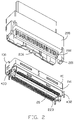
- FIG. 1 is a perspective view of an electrical connector assembly including the receptacle connector and the plug connector adapted to be mated with each other in a separated manner according to the invention
- FIG. 2 is another perspective view of the electrical connector assembly of FIG. 1 ;
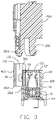
- FIG. 3 is a cross-sectional view of the electrical connector assembly of FIG. 1 ;
- FIG. 4 is a perspective view of the electrical connector assembly of FIG. 1 wherein the plug connector and the receptacle connector are mated with each other;
- FIG. 5 is across-sectional view of the electrical connector assembly of FIG. 4 ;
- FIG. 6 is a perspective view of the receptacle connector of the electrical connector assembly of FIG. 1 ;
- FIG. 7 is another perspective view of the receptacle connector of the electrical connector assembly of FIG. 6 ;
- FIG. 8 is an exploded perspective view of the receptacle connector of the electrical connector assembly of FIG. 7 ;
- FIG. 9 is another exploded perspective view of the receptacle connector of the electrical connector assembly of FIG. 8 ;
- FIG. 10 is a further exploded perspective view of the receptacle connector of the electrical connector assembly of FIG. 8 ;
- FIG. 11 is a perspective view of the electrical connector assembly according to another embodiment of the invention wherein the plug connector and the receptacle connector are separated from each other;
- FIG. 12 is another perspective view of the electrical connector assembly of FIG. 11 wherein the plug connector and the receptacle connector are mated with each other;
- FIG. 13 is a perspective view of the receptacle connector of the electrical connector assembly of FIG. 11 ;
- FIG. 14 is another perspective view of the receptacle connector of the electrical connector assembly of FIG. 13 ′
- FIG. 15 is an exploded perspective view of the receptacle connector of the electrical connector assembly of FIG. 13 ;
- FIG. 16 is a further exploded perspective view of the receptacle connector of the electrical connector assembly of FIG. 15 .
- An electrical connector assembly 500 includes a receptacle connector 100 and the plug connector 200 adapted to be connected with each other.
- the electrical connector assembly belongs to MCIO (Mini Cool Edge 10 ).
- the mating direction is the vertical direction.
- the plug connector 200 includes a mating tongue 201 with a plurality of plug contacts 202 thereon, and an extending plate 203 parallel to the mating tongue 201 with a deflectable latch 204 thereon.
- the extending plate 203 extends forwardly beyond the mating tongue 201 in the vertical direction Z.
- the receptacle connector 100 includes an insulative housing 10 enclosing a pair of contact modules 20 , an outer metallic shield 40 surrounding the housing 10 , and an inner metallic shield 30 attached upon one side of the housing 10 .
- the housing 10 includes a mating face 11 and a mounting face 12 opposite to each other in the vertical direction Z with a mating slot 13 extending along the longitudinal direction X and located under the mating face 11 .
- a first side wall 14 and the second side wall 15 are respectively located by two sides of the mating slot 13 in the transverse direction Y.
- Each of the first side wall 14 and the second side wall 15 extends in the longitudinal direction X.
- a pair of end walls 16 are connected between opposite ends of the first side wall 14 and the second side wall
- Each of the end walls 15 extends in the transverse direction Y.
- Each of the first side wall 14 and the second side wall 15 forms a plurality of passageways 17 to communicate with the mating slot 13 in the transverse direction Y.
- the housing 10 forms a mounting cavity 18 above the mounting face 12 so as to have the pair of contact modules 20 upwardly assembled thereinto.
- Each contact module 20 includes a plurality of contacts 22 integrally formed within an insulator 21 via insert-molding.
- Each insulator 21 includes corresponding coupling blocks 211 and the openings 212 so as to have the pair of contact modules 20 assembled together.
- Each insulator 21 further includes a plurality of protrusions 213 engaged within the corresponding holes 141 in the first side wall 14 and the second side wall 15 for fixing the pair of contact module 20 within the mounting cavity 18 of the housing 10 .
- Each contact 22 includes an upper contacting section 221 extending into the mating slot 13 , a lower mounting section 223 around the mounting face 12 , and a middle retaining section 222 therebetween.
- the outer metallic shield 40 includes a first side plate 41 extending in the longitudinal direction X and spaced from the first side wall 14 , a second side plate 42 extending along in the longitudinal direction X parallel to the first plate 41 and intimately covering the second side wall 15 , and a pair of end plates 43 spaced from each other over in the longitudinal direction in a parallel relation and intimately covering the end walls 16 , respectively.
- All the first plate 41 , the second side plate 42 and the pair of end plates 43 commonly form a receiving space 401 including, along the transverse direction Y, a primary/dwelling space 103 for retaining the housing 10 therein to form the complete receptacle connector 100 , and a secondary/locking space 102 communicatively beside the primary space for receiving the extending plate 203 of the plug 200 during mating.
- the first side plate 41 includes a pair of locking holes 413 for engagement with the locking lugs 206 of the latch 204 of the plug connector 200 .
- Both the first side plate 41 and the second side plate 42 includes protrusions 414 for reinforcement consideration.
- the inner metallic shield 30 is attached upon an exterior surface of the first side wall 14 to face the secondary space 102 . As shown in FIG. 9 , by the inner metallic shield 30 , the receiving space 401 of the outer metallic shield 40 is divided into the primary space 103 and the second space 102 .
- the upper edge 411 of the first side plate 41 is higher than both the upper face 11 and the upper edge 301 of the inner metallic shield 30
- the lower edge 412 is higher than the lower edge 302 of the inner metallic shield 30
- the mating face 11 is located between an upper edge and the lower edge of locking hole 413 in the vertical direction Z.
- Each end plate 43 includes a first portion (not labeled) connected to the first side plate 41 facing the secondary space 102 in the longitudinal direction, and a second portion (not labeled) intimately covering the corresponding end wall 16 .
- the primary space 103 is formed among the first side plate 41 , the first portions of the pair of end plates 43 and the inner metallic shield 30
- the secondary space 102 is formed among the second side plate 42 , the second portions of the pair of end plates 43 and the inner metallic shield 30
- the upper edge 301 of the inner metallic shield 30 is flush with or lower than the mating face 11
- the lower edge 302 of the inner metallic shield 30 is located above the mounting face 12 .
- the upper edge of the first portion 434 is higher than that of the second portion 435 and but being flush with the upper end of the 411 of the first side plate 41 .
- the exterior surface of the first side wall 14 forms a recess 142 to accommodate an inward offset 32 of the inner metallic shield 30 so as to receive the inward protrusion 206 of the extending plate 203 of the standard plug connector 200 without improper interference.
- the locking holes 413 in the first side plate 41 are essentially aligned with the cutout 32 in the transverse direction.
- the inner metallic shield 30 may include the protrusions similar to protrusions 414 on the outer metallic shield 40 for increasing engagement with the plug connector 200 .
- an inner surface of the inner metallic shield 30 may be applied with an insulative tape for avoiding any improper electrical connection between the inner metallic shield 30 and the outwardly deflected contacts 22 when the plug connector 200 is mated with the receptacle connector 100 .
- both the inner metallic shield 30 and the outer metallic shield 40 are discrete from each other and assembled downwardly to the housing 10 .
- the hooks 33 includes a first section 331 and a second section 332 , and the end wall 16 of the housing 10 forms a first portion 113 and the second portion 114 to receive the first section 331 and the second section 332 .
- the end wall 16 further forms a recess 143 below the first portion 113 in the vertical direction, and the end plate 43 forms an engagement tab 431 received within the recess 143 and located below the corresponding hook 33 .
- the inner metallic shield 30 and the outer metallic shield 40 are electrically connected with each other via abutment between the engagement tab 431 and the inner metallic shield 30 in the transverse direction.
- the end plate 43 includes a pair of legs 432 for mounting to the printed circuit board (not shown), and an engagement tab 433 between the pair of legs 432 to upwardly abut against a step (not labeled) of the end wall 16 for preventing upwardly movement of the outer metallic shield 40 from the housing 10 .
- the second side wall 15 includes a supporting bar 151 on which the lower edge 422 of the second side plate 42 downwardly abuts for preventing downward movement of the outer metallic shield 40 from the housing 10 .
- the extending plate 203 firstly enters the secondary space 102 and the mating tongue 201 successively enters the primary space 103 .
- the bottom edge of the extending plate 203 is located and exposed below the lower edge 413 of the first side plate 41 so as to indicate the full mating therebetween.
- the locking lug 205 of the latch 204 is engaged within the corresponding locking hole 413 .
- the extending plate 203 further includes an inward protrusion 206 opposite to the latch 204 to be snugly received within the cutout 32 of the inner metallic shield 30 so as to stabilize the mating between the plug connector 200 and the receptacle connector 100 .
- the receptacle connector 100 is further equipped with an inner metallic shield 30 to divide the receiving space into the primary space 103 for receiving the housing 10 , and a secondary space 102 for receiving the extending plate 203 of the plug connector 200 wherein the first side wall 14 forms the recess 142 to accommodate the inward offset 32 of the inner metallic shield 30 for receiving the inward protrusion 206 of the plug connector 200 .
- the inward offset 32 may provide reinforced structure to confront the inward protrusion 206 of the plug connector 200 in the transverse direction.
- the electrical connector assembly 500 includes a receptacle connector 100 ′ and the plug connector 200 ′ belonging to the Low Profile SlimSAS connector assembly.
- the second embodiment shown in FIGS. 11-16 no recess structure is formed in the first side wall 14 ′ and no inward offset is formed in the inner metallic shield 30 ′.
- the extending plate 203 ′ of the plug connector 200 ′ forms no inward protrusion.
- the contacts 22 are directly assembled into the corresponding passageways rather than via assistance of the insulator.
Landscapes
- Details Of Connecting Devices For Male And Female Coupling (AREA)
Abstract
Description
Claims (20)
Applications Claiming Priority (2)
| Application Number | Priority Date | Filing Date | Title |
|---|---|---|---|
| CN202010026403.9 | 2020-01-10 | ||
| CN202010026403.9A CN113193437B (en) | 2020-01-10 | 2020-01-10 | Electric connector and combination thereof |
Publications (2)
| Publication Number | Publication Date |
|---|---|
| US20210218197A1 US20210218197A1 (en) | 2021-07-15 |
| US11411355B2 true US11411355B2 (en) | 2022-08-09 |
Family
ID=76764044
Family Applications (1)
| Application Number | Title | Priority Date | Filing Date |
|---|---|---|---|
| US17/145,418 Active US11411355B2 (en) | 2020-01-10 | 2021-01-11 | Electrical connector assembly |
Country Status (3)
| Country | Link |
|---|---|
| US (1) | US11411355B2 (en) |
| CN (1) | CN113193437B (en) |
| TW (1) | TWI830979B (en) |
Families Citing this family (6)
| Publication number | Priority date | Publication date | Assignee | Title |
|---|---|---|---|---|
| CN113193436B (en) * | 2020-01-10 | 2022-07-26 | 富士康(昆山)电脑接插件有限公司 | Electric connector and combination thereof |
| US11431131B2 (en) * | 2020-05-23 | 2022-08-30 | Foxconn (Kunshan) Computer Connector Co., Ltd. | Electrical connector assembly |
| CN111834767B (en) * | 2020-07-15 | 2022-03-25 | 富士康(昆山)电脑接插件有限公司 | Electrical connector |
| US11894636B2 (en) | 2021-01-13 | 2024-02-06 | Foxconn (Kunshan) Computer Connector Co., Ltd. | Electrical connector with structure to secure a shield to an insulating body |
| CN114597713A (en) * | 2022-01-26 | 2022-06-07 | 富鼎精密工业(郑州)有限公司 | Electrical connector |
| CN117638533A (en) * | 2022-08-12 | 2024-03-01 | 超聚变数字技术有限公司 | Connector, adapter card module and computing equipment |
Citations (12)
| Publication number | Priority date | Publication date | Assignee | Title |
|---|---|---|---|---|
| US20040058572A1 (en) | 2002-06-21 | 2004-03-25 | Fromm Galen F. | High-density, impedance-tuned connector having modular construction |
| US20080020654A1 (en) * | 2006-07-18 | 2008-01-24 | Hon Hai Precision Ind. Co., Ltd. | Upright electrical connector |
| US20090318025A1 (en) * | 2008-06-16 | 2009-12-24 | Yazaki Corporation | Shield connector |
| CN202872038U (en) | 2012-08-21 | 2013-04-10 | 香港商安费诺(东亚)有限公司 | Signal connector for reinforcing and stabilizing connecting structure |
| US20140199874A1 (en) | 2013-01-11 | 2014-07-17 | Molex Incorporated | Electrical connection device |
| USD713349S1 (en) | 2013-08-01 | 2014-09-16 | Tyco Electronics Japan G.K. | Electrical connector |
| TWM499692U (en) | 2014-12-23 | 2015-04-21 | Santa Electronics Inc | Improved structure for electrical connector |
| CN208045830U (en) | 2018-02-11 | 2018-11-02 | 香港商安费诺(东亚)有限公司 | Connector with docking groove |
| CN208608459U (en) | 2018-07-25 | 2019-03-15 | 安费诺电子装配(厦门)有限公司 | A kind of structure reducing latch connector height |
| US20190173232A1 (en) | 2017-12-01 | 2019-06-06 | Amphenol East Asia Ltd. | Compact electrical connector |
| CN209561681U (en) | 2019-02-12 | 2019-10-29 | 安费诺电子装配(厦门)有限公司 | A kind of connector and connector assembly |
| US20200403338A1 (en) | 2019-06-18 | 2020-12-24 | Foxconn (Kunshan) Computer Connector Co., Ltd. | Plug connector |
Family Cites Families (2)
| Publication number | Priority date | Publication date | Assignee | Title |
|---|---|---|---|---|
| TWM538265U (en) * | 2016-07-13 | 2017-03-11 | 宣德科技股份有限公司 | Electrical connector |
| CN110391518B (en) * | 2018-04-23 | 2022-07-26 | 富顶精密组件(深圳)有限公司 | Electrical connector |
-
2020
- 2020-01-10 CN CN202010026403.9A patent/CN113193437B/en active Active
-
2021
- 2021-01-07 TW TW110100636A patent/TWI830979B/en active
- 2021-01-11 US US17/145,418 patent/US11411355B2/en active Active
Patent Citations (12)
| Publication number | Priority date | Publication date | Assignee | Title |
|---|---|---|---|---|
| US20040058572A1 (en) | 2002-06-21 | 2004-03-25 | Fromm Galen F. | High-density, impedance-tuned connector having modular construction |
| US20080020654A1 (en) * | 2006-07-18 | 2008-01-24 | Hon Hai Precision Ind. Co., Ltd. | Upright electrical connector |
| US20090318025A1 (en) * | 2008-06-16 | 2009-12-24 | Yazaki Corporation | Shield connector |
| CN202872038U (en) | 2012-08-21 | 2013-04-10 | 香港商安费诺(东亚)有限公司 | Signal connector for reinforcing and stabilizing connecting structure |
| US20140199874A1 (en) | 2013-01-11 | 2014-07-17 | Molex Incorporated | Electrical connection device |
| USD713349S1 (en) | 2013-08-01 | 2014-09-16 | Tyco Electronics Japan G.K. | Electrical connector |
| TWM499692U (en) | 2014-12-23 | 2015-04-21 | Santa Electronics Inc | Improved structure for electrical connector |
| US20190173232A1 (en) | 2017-12-01 | 2019-06-06 | Amphenol East Asia Ltd. | Compact electrical connector |
| CN208045830U (en) | 2018-02-11 | 2018-11-02 | 香港商安费诺(东亚)有限公司 | Connector with docking groove |
| CN208608459U (en) | 2018-07-25 | 2019-03-15 | 安费诺电子装配(厦门)有限公司 | A kind of structure reducing latch connector height |
| CN209561681U (en) | 2019-02-12 | 2019-10-29 | 安费诺电子装配(厦门)有限公司 | A kind of connector and connector assembly |
| US20200403338A1 (en) | 2019-06-18 | 2020-12-24 | Foxconn (Kunshan) Computer Connector Co., Ltd. | Plug connector |
Also Published As
| Publication number | Publication date |
|---|---|
| TW202133503A (en) | 2021-09-01 |
| US20210218197A1 (en) | 2021-07-15 |
| CN113193437B (en) | 2022-06-24 |
| CN113193437A (en) | 2021-07-30 |
| TWI830979B (en) | 2024-02-01 |
Similar Documents
| Publication | Publication Date | Title |
|---|---|---|
| US11411355B2 (en) | Electrical connector assembly | |
| US20230253724A1 (en) | Electrical connector with cavity between terminals | |
| US11575231B2 (en) | Electrical connector assembly | |
| US7232316B2 (en) | Electrical connector with improved shielding means | |
| US9502827B2 (en) | Electrical connector with improved metal shell | |
| US6726492B1 (en) | Grounded electrical connector | |
| US9450355B2 (en) | USB plug connector and method for manufacturing the same | |
| US6431914B1 (en) | Grounding scheme for a high speed backplane connector system | |
| US10468827B2 (en) | Electrical connector having an improved isolation block | |
| US5772453A (en) | Side-by-side dual port USB connector | |
| US9287668B2 (en) | I/O plug connector adapted for normal insertion and reverse insertion into I/O receptacle connector and connector assembly having the two | |
| US11431131B2 (en) | Electrical connector assembly | |
| US7134900B2 (en) | Electrical connector assembly with multi-function latching member | |
| US9893468B2 (en) | Electrical connector assembly having improved shielding shell | |
| US7857665B2 (en) | Electrical connector with improved contact arrangement | |
| US10797450B2 (en) | Electrical connector with unitary metallic shell having outer part and inner part with transitional region therebetween | |
| US7168985B1 (en) | Electrical connector assembly having an improved inner shield | |
| US20160329662A1 (en) | Electrical connector and electrical connector assembly thereof | |
| US5178557A (en) | Electric connector having symmetric locking blocks at opposite ends | |
| US6767251B2 (en) | Electrical connector supported on printed circuit board | |
| US20050042924A1 (en) | Electrical connector having shielding plates | |
| US7491083B2 (en) | Electrical connector assembly | |
| EP2434589B1 (en) | Shield case, connector having the shield case, and electronic equipment having the connector | |
| JP2021174770A (en) | Board side connector and connector assembly | |
| WO2016199831A1 (en) | Plug connector for transceiver module, receptacle assembly for transceiver module, and transceiver module assembly |
Legal Events
| Date | Code | Title | Description |
|---|---|---|---|
| AS | Assignment |
Owner name: FOXCONN (KUNSHAN) COMPUTER CONNECTOR CO., LTD., CHINA Free format text: ASSIGNMENT OF ASSIGNORS INTEREST;ASSIGNORS:LV, LAI-HANG;CHEN, DE-JIN;FENG, XIAN-WEI;AND OTHERS;SIGNING DATES FROM 20201120 TO 20201216;REEL/FRAME:054868/0908 Owner name: FOXCONN INTERCONNECT TECHNOLOGY LIMITED, CAYMAN ISLANDS Free format text: ASSIGNMENT OF ASSIGNORS INTEREST;ASSIGNORS:LV, LAI-HANG;CHEN, DE-JIN;FENG, XIAN-WEI;AND OTHERS;SIGNING DATES FROM 20201120 TO 20201216;REEL/FRAME:054868/0908 |
|
| FEPP | Fee payment procedure |
Free format text: ENTITY STATUS SET TO UNDISCOUNTED (ORIGINAL EVENT CODE: BIG.); ENTITY STATUS OF PATENT OWNER: LARGE ENTITY |
|
| STPP | Information on status: patent application and granting procedure in general |
Free format text: APPLICATION DISPATCHED FROM PREEXAM, NOT YET DOCKETED |
|
| STPP | Information on status: patent application and granting procedure in general |
Free format text: DOCKETED NEW CASE - READY FOR EXAMINATION |
|
| STPP | Information on status: patent application and granting procedure in general |
Free format text: EX PARTE QUAYLE ACTION MAILED |
|
| STPP | Information on status: patent application and granting procedure in general |
Free format text: RESPONSE TO EX PARTE QUAYLE ACTION ENTERED AND FORWARDED TO EXAMINER |
|
| STPP | Information on status: patent application and granting procedure in general |
Free format text: NOTICE OF ALLOWANCE MAILED -- APPLICATION RECEIVED IN OFFICE OF PUBLICATIONS |
|
| STPP | Information on status: patent application and granting procedure in general |
Free format text: NOTICE OF ALLOWANCE MAILED -- APPLICATION RECEIVED IN OFFICE OF PUBLICATIONS |
|
| STCF | Information on status: patent grant |
Free format text: PATENTED CASE |