US11411225B2 - Chambered frame insert - Google Patents
Chambered frame insert Download PDFInfo
- Publication number
- US11411225B2 US11411225B2 US16/648,988 US201816648988A US11411225B2 US 11411225 B2 US11411225 B2 US 11411225B2 US 201816648988 A US201816648988 A US 201816648988A US 11411225 B2 US11411225 B2 US 11411225B2
- Authority
- US
- United States
- Prior art keywords
- ribs
- frame insert
- chambers
- outer member
- frame
- Prior art date
- Legal status (The legal status is an assumption and is not a legal conclusion. Google has not performed a legal analysis and makes no representation as to the accuracy of the status listed.)
- Active
Links
Images


Classifications
-
- H—ELECTRICITY
- H01—ELECTRIC ELEMENTS
- H01M—PROCESSES OR MEANS, e.g. BATTERIES, FOR THE DIRECT CONVERSION OF CHEMICAL ENERGY INTO ELECTRICAL ENERGY
- H01M50/00—Constructional details or processes of manufacture of the non-active parts of electrochemical cells other than fuel cells, e.g. hybrid cells
- H01M50/40—Separators; Membranes; Diaphragms; Spacing elements inside cells
- H01M50/463—Separators, membranes or diaphragms characterised by their shape
-
- H—ELECTRICITY
- H01—ELECTRIC ELEMENTS
- H01M—PROCESSES OR MEANS, e.g. BATTERIES, FOR THE DIRECT CONVERSION OF CHEMICAL ENERGY INTO ELECTRICAL ENERGY
- H01M4/00—Electrodes
- H01M4/02—Electrodes composed of, or comprising, active material
- H01M4/64—Carriers or collectors
- H01M4/70—Carriers or collectors characterised by shape or form
- H01M4/72—Grids
- H01M4/73—Grids for lead-acid accumulators, e.g. frame plates
-
- H—ELECTRICITY
- H01—ELECTRIC ELEMENTS
- H01M—PROCESSES OR MEANS, e.g. BATTERIES, FOR THE DIRECT CONVERSION OF CHEMICAL ENERGY INTO ELECTRICAL ENERGY
- H01M10/00—Secondary cells; Manufacture thereof
- H01M10/04—Construction or manufacture in general
- H01M10/0413—Large-sized flat cells or batteries for motive or stationary systems with plate-like electrodes
- H01M10/0418—Large-sized flat cells or batteries for motive or stationary systems with plate-like electrodes with bipolar electrodes
-
- H—ELECTRICITY
- H01—ELECTRIC ELEMENTS
- H01M—PROCESSES OR MEANS, e.g. BATTERIES, FOR THE DIRECT CONVERSION OF CHEMICAL ENERGY INTO ELECTRICAL ENERGY
- H01M10/00—Secondary cells; Manufacture thereof
- H01M10/36—Accumulators not provided for in groups H01M10/05-H01M10/34
- H01M10/365—Zinc-halogen accumulators
-
- H—ELECTRICITY
- H01—ELECTRIC ELEMENTS
- H01M—PROCESSES OR MEANS, e.g. BATTERIES, FOR THE DIRECT CONVERSION OF CHEMICAL ENERGY INTO ELECTRICAL ENERGY
- H01M2300/00—Electrolytes
- H01M2300/0002—Aqueous electrolytes
-
- Y—GENERAL TAGGING OF NEW TECHNOLOGICAL DEVELOPMENTS; GENERAL TAGGING OF CROSS-SECTIONAL TECHNOLOGIES SPANNING OVER SEVERAL SECTIONS OF THE IPC; TECHNICAL SUBJECTS COVERED BY FORMER USPC CROSS-REFERENCE ART COLLECTIONS [XRACs] AND DIGESTS
- Y02—TECHNOLOGIES OR APPLICATIONS FOR MITIGATION OR ADAPTATION AGAINST CLIMATE CHANGE
- Y02E—REDUCTION OF GREENHOUSE GAS [GHG] EMISSIONS, RELATED TO ENERGY GENERATION, TRANSMISSION OR DISTRIBUTION
- Y02E60/00—Enabling technologies; Technologies with a potential or indirect contribution to GHG emissions mitigation
- Y02E60/10—Energy storage using batteries
-
- Y—GENERAL TAGGING OF NEW TECHNOLOGICAL DEVELOPMENTS; GENERAL TAGGING OF CROSS-SECTIONAL TECHNOLOGIES SPANNING OVER SEVERAL SECTIONS OF THE IPC; TECHNICAL SUBJECTS COVERED BY FORMER USPC CROSS-REFERENCE ART COLLECTIONS [XRACs] AND DIGESTS
- Y02—TECHNOLOGIES OR APPLICATIONS FOR MITIGATION OR ADAPTATION AGAINST CLIMATE CHANGE
- Y02P—CLIMATE CHANGE MITIGATION TECHNOLOGIES IN THE PRODUCTION OR PROCESSING OF GOODS
- Y02P70/00—Climate change mitigation technologies in the production process for final industrial or consumer products
- Y02P70/50—Manufacturing or production processes characterised by the final manufactured product
Definitions
- the present invention relates to a chambered frame insert for a static, zinc-halogen rechargeable battery.
- batteries such as zinc-halide batteries, including improving the performance of the batteries.
- aqueous batteries using a dissolved salt as a combined anolyte/catholyte, such as zinc-bromine or other zinc-halide technologies suffer from performance loss due to stratification.
- a frame insert according to the present invention performance of zinc-halide batteries can be significantly improved.
- stratification occurs in aqueous batteries using a dissolved salt when, after multiple cycles, the amount of dissolved salt in the electrolyte becomes non-uniform as a function of cell height. These salt distribution changes cause the electrolyte to separate into a less dense layer (top) and a more dense layer (bottom). This effect is particularly severe in taller, narrower cell formats.
- one aspect of the disclosure provides a frame insert for an electrolyte chamber of a battery.
- the frame insert has a plurality of ribs extending laterally and defining a plurality of chambers.
- the plurality of ribs are angled (i.e., slanted) with respect to a horizontal lateral axis of the frame insert.
- a plurality of voids are defined in the plurality of ribs that allow gas to travel between the plurality of chambers.
- Implementations of the disclosure may include one or more of the following optional features.
- the plurality of voids are a plurality of slots.
- the plurality of voids are laterally staggered across the plurality of ribs.
- the plurality of voids are defined in a longitudinal face of the ribs.
- the plurality of voids are near or adjacent to the upward most lateral ends of the plurality of ribs.
- the voids such as a staggered series of small slots formed in the anode side of the ribs, allow evolved gas to escape.
- the frame insert further includes an outer member surrounding the plurality of ribs and joined to the plurality of ribs at a lateral end of the plurality of ribs. In some embodiments, the frame insert further includes a central member extending in a lateral vertical direction within the outer member and joined to the outer member. In some embodiments, a majority of the plurality of ribs extend from the central member to the outer member.
- the outer member laterally surrounds the plurality of ribs and is joined to the plurality of ribs at an outer lateral end of the ribs and the central member extends from a first position of the outer member to a second position of the outer member and the central member is joined to a majority of the plurality of ribs at an inner lateral end of the ribs.
- the joints between the plurality of ribs and the outer member and the joints between the plurality of ribs and the central member are rounded, such that the plurality of chambers defined by the plurality of ribs, outer member, and central member have rounded corners.
- a majority of the plurality of chambers defined by the plurality of ribs, outer member, and central member are substantially parallelogrammatic or trapezoidal.
- the plurality of ribs extend at an angle above the horizontal lateral axis from the central member to the outer member. In some embodiments, a majority of the plurality of chambers have consistent height across their length. In some embodiments, a majority of the plurality of chambers are of the same height as one another.
- a battery i.e., a rechargeable battery having an anode, a cathode, an aqueous dissolved salt electrolyte, a frame, and a frame insert.
- the frame insert includes a plurality of ribs extending laterally and defining a plurality of chambers, where the plurality of ribs are angled with respect to a horizontal lateral axis of the frame insert.
- the electrolyte at least partially fills a plurality of chambers of the frame insert.
- the aqueous dissolved salt electrolyte is a zinc-halide electrolyte.
- the frame insert is laterally supported by the frame. In some embodiments, the frame insert is longitudinally supported by one or more of the cathode, the anode and the frame.
- the frame insert of the batter further includes a plurality of voids defined in the plurality of ribs that allow gas to travel between the plurality of chambers.
- the plurality of voids are defined in a front face of the plurality of ribs, and the front face is adjacent to the anode.
- the electrolyte fully fills the plurality of chambers except for a head space at the uppermost chamber(s).
- FIG. 1 is a perspective view of a frame insert.
- FIG. 2 is a front view of the frame insert of FIG. 1 inserted into a battery frame.
- FIG. 3 is a cross-sectional diagram of a battery with an anode, cathode, frame, and frame insert.
- FIG. 4 is a plot showing discharge capacity as a function of cycle index for zinc-halide cells with and without a frame insert at 100% and 75% of maximum (“milestone”) rates.
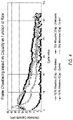
- FIG. 5 is a plot showing average cell discharge voltage as a function of cycle index for zinc-halide cells with and without a frame insert at 100% and 75% of maximum (“milestone”) rates.
- Example configurations will now be described more fully with reference to the accompanying drawings.
- Example configurations are provided so that this disclosure will be thorough, and will fully convey the scope of the disclosure to those of ordinary skill in the art. Specific details are set forth such as examples of specific components, devices, and methods, to provide a thorough understanding of configurations of the present disclosure. It will be apparent to those of ordinary skill in the art that specific details need not be employed, that example configurations may be embodied in many different forms, and that the specific details and the example configurations should not be construed to limit the scope of the disclosure.
- first, second, third, etc. may be used herein to describe various elements, components, regions, layers and/or sections. These elements, components, regions, layers and/or sections should not be limited by these terms. These terms may be only used to distinguish one element, component, region, layer or section from another region, layer or section. Terms such as “first,” “second,” and other numerical terms do not imply a sequence or order unless clearly indicated by the context. Thus, a first element, component, region, layer or section discussed below could be termed a second element, component, region, layer or section without departing from the teachings of the example configurations.
- the term “static” refers to batteries that comprise a liquid electrolyte, wherein the liquid electrolyte is not circulated (via a pump or the like) from a reservoir to the site of electrochemical activity (e.g., oxidation and/or reduction of a battery electrode).
- battery encompasses electrical storage devices comprising at least one electrochemical cell.
- a “secondary battery” or simply a “rechargeable battery” is rechargeable, whereas a “primary battery” is not rechargeable.
- a battery anode is designated as the positive electrode during discharge, and as the negative electrode during charge.
- electrochemical cell or “cell” are used interchangeably to refer to a device capable of either generating electrical energy from chemical reactions or facilitating chemical reactions through the introduction of electrical energy.
- Electrolytes refers to a substance that behaves as an ionically conductive medium.
- the electrolyte facilitates the mobilization of electrons and cations in the cell.
- Electrolytes include mixtures of materials such as aqueous solutions of metal halide salts (e.g., ZnBr 2 , ZnCl 2 , or the like).
- Electrode refers to an electrical conductor used to make contact with a nonmetallic part of a circuit (e.g., a semiconductor, an electrolyte, or a vacuum).
- An electrode may also refer to either an anode or a cathode.
- anode refers to the negative electrode from which electrons flow during the discharging phase in the battery.
- the anode is also the electrode that undergoes chemical oxidation during the discharging phase.
- the anode is the electrode that undergoes chemical reduction during the cell's charging phase.
- Anodes are formed from electrically conductive or semiconductive materials, e.g., metals (e.g., titanium or TiC coated titanium), metal oxides, metal alloys, metal composites, semiconductors, or the like.
- cathode refers to the positive electrode into which electrons flow during the discharging phase in the battery.
- the cathode is also the electrode that undergoes chemical reduction during the discharging phase.
- the cathode is the electrode that undergoes chemical oxidation during the cell's charging phase.
- Cathodes are formed from electrically conductive or semiconductive materials, e.g., metals, metal oxides, metal alloys, metal composites, semiconductors, or the like.
- bipolar electrode refers to an electrode that functions as the anode of one cell and the cathode of another cell.
- a bipolar electrode functions as an anode in one cell and functions as a cathode in an immediately adjacent cell.
- a bipolar electrode comprises two surfaces, a cathode surface and an anode surface, wherein the two surfaces are connected by a conductive material.
- a bipolar electrode plate may have opposing surfaces wherein one surface is the anode surface, the other surface is the cathode surface, and the conductive material is the thickness of the plate between the opposing surfaces.
- halide refers to a binary compound of a halogen with another element or radical that is less electronegative (or more electropositive) than the halogen, to make a fluoride, chloride, bromide, iodide, or astatide compound.
- halogen refers to any of the elements fluorine, chlorine, bromine, iodine, and astatine, occupying group VIIA (17) of the periodic table. Halogens are reactive nonmetallic elements that form strongly acidic compounds with hydrogen, from which simple salts can be made.
- glycol refers to an ether (e.g., a glycol ether).
- examples include, but are not limited to, monoglyme (i.e., 1,2-dimethoxyethane), diglyme (i.e., bis(2-methoxyethyl) ether, tetraglyme (i.e., tetraethylene glycol dimethyl ether), pentaglyme, hexaglyme, heptaglyme, or any combination thereof.
- a “titanium material” may include, but is not limited to, titanium (in any oxidation state), TiC, alloys of TiC such as TiC x M (where x is 0, 1, 2, 3, or 4 and M is a metal), titanium carbohyrides, titanium oxycarbides, titanium oxynitrides, titanium oxycarbonitrides, titanium suboxides, non-stoichiometric titanium-carbon compounds, and any combination thereof.
- titanium carbide is used interchangeably with “titanium carbide material” and includes, but is not limited to TiC, alloys of TiC such as TiC x M (where x is 0, 1, 2, 3, or 4 and M is a metal), titanium carbohyrides, non-stoichiometric titanium-carbon compounds, and combinations thereof.
- zinc metal refers to elemental zinc, also commonly known as Zn(0) or Zn 0 .
- a frame insert 2 is shown in a perspective view with horizontal lateral axis X, vertical lateral axis Y, and longitudinal axis Z.
- the frame insert 2 comprises a plurality of ribs 4 defining a plurality of chambers 6 .
- the ribs 4 are slanted at an angle ⁇ relative to the horizontal lateral axis X.
- the ribs 4 may have a square or rectangular cross-section.
- the ribs 4 join to outer member 12 and/or central member 14 via joints, e.g., rounded joints.
- the majority of the ribs 4 may be uniform in length, cross-section, angle and distance from one another so as to define a plurality of chambers 6 of the same size and shape.
- the ribs 4 may have a shorter length and may define a chamber 6 with a different (e.g., smaller) size and different shape.
- the ribs 4 are positioned to reduce performance losses due to stratification by defining chambers 6 with a height that is less than the height of the primary electrolyte chamber.
- the ribs 4 may be straight across their length. Alternatively, the ribs 4 may be curved across their length.
- the ribs 4 may be parallel to each other in order to define chambers 6 of consistent height across the length of the chamber.
- the ribs 4 may be spaced apart by an equal distance to define chambers 6 of equal height to one another.
- the ribs 4 may have a V-shape or concave shape across their length to promote convective mixing.
- the V-shaped or concave shaped ribs 4 may be divided by a central member 14 .
- the outer member 12 of the frame insert 2 surrounds the ribs 4 and is joined to the ribs 4 at outer lateral ends 10 of the ribs 4 .
- the central member 14 extends through the center of the frame insert 2 from a first position on the outer member 12 to a second position on the outer member 12 .
- the central member 14 bisects the outer member 12 .
- the ribs 4 extend between the central member 14 and the outer member 12 and are joined to the central member 14 at central lateral ends 16 of the ribs 4 .
- the outer member 12 has top ( 12 a ), bottom ( 12 b ), left ( 12 c ) and right ( 12 d ) sections that form a rectangle or square, e.g., with rounded corners.
- the central member 14 bisects the outer member 12 extending from the top 12 a to the bottom 12 b .
- the outer member 12 and/or central member 14 may have a square or rectangular cross-section.
- the ribs 4 may extend at an angle upwards and to the right on one side of the central member 14 (e.g., toward the right section 12 d of the outer member 12 relative to the view of FIG. 1 ) and upwards and to the left on the other side of the central member 14 (e.g., toward the left section 12 c of the outer member 12 relative to the view of FIG. 1 ).
- the central member 14 may be absent and the ribs 4 may extend in a V-shape or concave shape across the frame insert 2 .
- the plurality of ribs 4 , outer member 12 , and central member 14 cooperate to define the plurality of chambers 6 .
- the plurality of chambers 6 have a height, h, that is less than the height of the primary electrolyte chamber that receives the frame insert 2 .
- the reduced height, h, of the chambers 6 reduces stratification of the electrolyte, as more dense species (i.e., salts) within the electrolyte are restricted from settling at the bottom of the primary electrolyte chamber by the ribs 4 .
- FIG. 1 shows the ribs 4 slanted at an angle ⁇ relative to the horizontal lateral axis X. The ribs 4 promote convection of electrolyte within the chambers 6 .
- the chambers 6 may define a parallelogrammatic or trapezoidal cross-sectional shape.
- chambers 6 at the top and bottom of the frame insert 2 e.g., at the top and bottom sections 12 a , 12 b of the outer member 12 relative to the view of FIG. 1
- the chambers 6 may have rounded corners 18 where the joint between the ribs 4 and the outer member 12 is rounded and/or the joint between the ribs 4 and the central member 14 is rounded.
- the plurality of ribs 4 define a plurality of voids 8 .
- Each void 8 is formed as a slot on a longitudinal-facing face 4 a (e.g., front face) of each rib 4 .
- the voids 8 are staggered in their position along the lateral length of the ribs 4 .
- the voids 8 (e.g., slots) of the frame insert 2 allow gas to travel between the chambers 6 and allow gas within the electrolyte to escape the frame insert 2 and exit the battery to reduce pressure build-up within the battery.
- the chambers 6 near the top of the frame insert 2 e.g., near the top section 12 a of the outer member 12 relative to the view of FIG.
- the voids 8 may be positioned adjacent or near the outer lateral ends 10 of the ribs 4 and adjacent to or near the outer member 12 (e.g., adjacent or near the left and right sections 12 c , 12 d of the outer member 12 relative to the view of FIG. 1 ).
- the voids 8 may be staggered along a lateral length of the ribs 4 extending from the central member 14 toward a corresponding one of the left section 12 c of the outer member 12 or the right section 12 d of the outer member 12 .
- Each void 8 may be defined by a rectangular-shaped recess formed in the front face 4 a of the corresponding rib 4 .
- the voids 8 When installed in a battery, the voids 8 may be adjacent to the anode of the battery, i.e., formed in the ribs 4 on the anode side of the frame insert 2 .
- the frame insert 2 may be manufactured by injection molding or other suitable means and may be made out of plastic or another suitable material.
- FIG. 2 a front view of an assembly 100 with the frame insert 2 inserted within a frame 120 .
- the frame insert 2 is longitudinally supported by an inner frame flange 122 and laterally supported by an inner frame edge 123 .
- An inner frame member 124 may also provide additional longitudinal support for the frame insert 2 , e.g., with an electrode (not shown) located between the frame insert 2 and the inner frame member 124 .
- the frame 120 may also support an anode, a cathode and an electrolyte of a battery.
- the frame 120 may be a frame as described in application No. 62/549,667, filed Aug. 24, 2017, the entire contents of which are incorporated herein by reference.
- FIG. 3 a cross-sectional diagram of a rechargeable battery 200 with multiple cells, each cell having a frame 120 , anode 226 , cathode 228 , and a frame insert 2 .
- the anode 226 and cathode 228 form a bipolar electrode 230 .
- the insert 2 is located (i.e., sandwiched) between adjacent bipolar electrodes 230 .
- the insert 2 , the anode 226 , and the cathode 228 of each cell are surrounded by and supported by a corresponding frame 120 .
- each frame 120 holds a corresponding frame insert 2 and a corresponding bipolar electrode 230 .
- Electrolyte is present within chambers 6 (see FIGS.
- the frame 120 may comprise a pressure release valve and/or electrolyte fill hole.
- the voids 8 are formed in the insert 2 on the side of the insert 2 that is adjacent to the anode 226 .
- Adjacent frames 120 may be sealed together to prevent leaking of electrolyte, e.g., with an O-ring.
- the electrolyte is a zinc halide electrolyte.
- the electrolyte may be an aqueous or non-aqueous (e.g., deep eutectic) zinc-halide electrolyte.
- any suitable zinc halide electrolyte may be used within the scope of the invention.
- electrolytes described in PCT Publication No. WO 2016/057477, filed Oct. 6, 2015, US Publication No. 2017/0194666, filed Mar. 29, 2016, and PCT Application No. PCT/US2017/033028, filed May 17, 2017, all of which are incorporated herein by reference may be used within the scope of the invention.
- zinc bromide, zinc chloride, or any combination of the two, present in the electrolyte act as the electrochemically active material.
- the electrolyte for use in a secondary zinc bromine electrochemical cell may comprise from about 30 wt % to about 40 wt % of ZnCl 2 or ZnBr 2 ; from about 5 wt % to about 15 wt % of KBr; from about 5 wt % to about 15 wt % of KCl; and one or more quaternary ammonium agents, wherein the electrolyte comprises from about 0.5 wt % to about 10 wt % of the one or more quaternary ammonium agents.
- the electrolyte comprises from about 4 wt % to about 12 wt % (e.g., from about 6 wt % to about 10 wt %) of potassium bromide (KBr). In some embodiments, the electrolyte comprises from about 8 wt % to about 12 wt % of potassium bromide (KBr).
- the electrolyte comprises from about 4 wt % to about 12 wt % (e.g., from about 6 wt % to about 10 wt %) of potassium chloride (KCl). In some embodiments, the electrolyte comprises from about 8 wt % to about 14 wt % of potassium chloride (KCl). In some embodiments, the electrolyte comprises from about 11 wt % to about 14 wt % of potassium chloride (KCl).
- the aqueous electrolyte comprises from about 25 wt % to about 70 wt % of ZnBr 2 ; from about 5 wt % to about 50 wt % of water; and from about 0.05 wt % to about 10 wt % of one or more quaternary ammonium agents.
- the aqueous electrolyte comprises from about 25 wt % to about 40 wt % of ZnBr 2 ; from about 25 wt % to about 50 wt % water; from about 5 wt % to about 15 wt % of KBr; from about 5 wt % to about 15 wt % of KCl; and from about 0.5 wt % to about 10 wt % of the one or more quaternary ammonium agents.
- the one or more quaternary ammonium agents comprises a quaternary agent selected from the group consisting of ammonium chloride, tetraethylammonium bromide, tetraethylammonium chloride, trimethylpropylammonium bromide, triethylmethyl ammonium chloride, trimethylpropylammonium chloride, butyltrimethylammonium chloride, trimethylethyl ammonium chloride, N-methyl-N-ethylmorpholinium bromide, N-methyl-N-ethylmorpholinium bromide (MEMBr), 1-ethyl-1-methylmorpholinium bromide, N-methyl-N-butylmorpholinium bromide, N-methyl-N-ethylpyrrolidinium bromide, N,N,N-triethyl-N-propylammonium bromide, N-ethyl-N-propylpyrrolidinium bromide, N
- the one or more quaternary ammonium agents comprises an alkyl substituted pyridinium chloride, an alkyl substituted pyridinium bromide, an alkyl substituted morpholinium chloride, an alkyl substituted morpholinium bromide, an alkyl substituted pyrrolidinium chloride, an alkyl substituted pyrrolidinium bromide, or any combination thereof.
- the electrolyte comprises one or more additional components such as a glyme (e.g., monoglyme, diglyme, triglyme, tetraglyme, pentaglyme, hexaglyme, or any combination thereof), an ether (e.g., DME-PEG, dimethyl ether, or a combination thereof), an alcohol (e.g., methanol, ethanol, 1-propanol, isopropanol, 1-butanol, sec-butanol, iso-butanol, tert-butanol, or any combination thereof), a glycol (e.g., ethylene glycol, propylene glycol, 1,3-butylene glycol, 1,4-butylene glycol, neopentyl glycol, hexalene glycol, or any combination thereof), an additive (e.g., Sn, In, Ga, Al, Tl, Bi, Pb, Sb, Ag, Mn, Fe
- the electrolyte consists of zinc bromide, 27.42 wt %; water, 44.34 wt %; potassium bromide, 6.78 wt %; potassium chloride, 9.83%; 2,5,8,11, 14-pentaoxapentadecane, 2.58 wt %; 4-ethyl-4-methylmorpholin-4-ium bromide, 1.03 wt %; tetraethylammonium bromide, 2.03 wt %; triethylmethylammonium chloride, 1.94 wt %; methoxypolyethylene glycol MW 2000, 1.29 wt %; methoxypolyethylene glycol MW 1000, 0.32 wt %; 2,2-dimethyl-1,3-propanediol, 1.29 wt %; 2-methylpropan-2-ol, 0.32 wt %; hexadecyltrimethylammonium bromide, 0.06
- the electrolyte consists of zinc bromide, 35.41 wt %; water, 38.84 wt %; potassium bromide, 5.54 wt %; potassium chloride, 11.09 wt %; triethylmethylammonium chloride, 5.8 wt %; polyethyleneglycol dimethyl ether (MW 2000), 1.26 wt %; polyethyleneglycol dimethyl ether (MW 1000), 0.35 wt %; 2,2-dimethylpropane-1,3-diol, 1 wt %; polydimethylsiloxane trimethylsiloxy terminated (MW 1250), 0.2 wt %; indium chloride, 7 ppm; and tin chloride, 7 ppm.
- electrolyte aqueous dissolved salt electrolyte species
- electrolyte aqueous dissolved salt electrolyte species
- Rechargeable batteries of the present invention comprise an anode and a cathode.
- the electrodes may be bipolar electrodes with an anode on the front surface and a cathode on the back surface of a bipolar electrode plate.
- the bipolar electrode plate comprises a conductive material that is relatively inert to zinc halide electrolyte used in the battery.
- the bipolar electrode plate comprises a titanium material (e.g., titanium or titanium oxide).
- the bipolar electrode plate further comprises a coating or film that covers at least a portion of the front (anode) and/or back (cathode) surfaces.
- the electrode plate comprises a titanium material coated with a titanium carbide material.
- the bipolar electrode plate comprises an electrically conductive carbon felt, e.g. a loaded carbon felt such as those described in U.S. provisional application No. 62/427,983, filed Nov. 30, 2016, the entire contents of which are incorporated herein by reference.
- the bipolar electrode is a bipolar electrode having a cathode assembly comprising a carbon material a separator and a cathode cage, such as those described in PCT Publication No. WO 2016/057457, filed Oct. 6, 2015, the entire contents of which are incorporated herein by reference.
- Zinc-halide battery stacks were assembled with a chambered frame insert according to the present invention. Control batteries were assembled without a frame insert.
- Each of the battery stacks (test battery stacks with and without the chambered frame insert) were assembled using a titanium carbide bipolar electrode plate and a titanium carbide anode terminal plate.
- Soft graphite felt (G250 AvCarb®) was adhesively bonded to the cathode surface or face of the bipolar electrode plate using graphite filled PVDF/methacrylate adhesive from Astro Chemicals, which was applied as a substantially uniform coating over the portion of the cathode surface that was covered by the graphite felt.
- a titanium carbide current collector having an open box configuration was laser welded to cover the central region of the exterior surface of the anode terminal plate, and a CP2 grade titanium stem was impact welded to the center of this current collector to provide the anode battery stack terminal.
- a titanium carbide current collector having an open box configuration was laser welded to cover the central region of the exterior surface (opposite of the cathode surface) of the bipolar electrode plate in the battery stack, and a CP2 grade titanium stem was impact welded to the center of this current collector to provide the cathode battery stack terminal.
- the bipolar electrode plate and the terminal anode plate were placed in PVC frames (with and without chambered frame inserts), and the PVC frames were bolted together under compression between metal (steel) endplates using tie rods, washers, and nuts to provide a dry battery stack.
- Each of the metal endplates included through holes adapted to provide access to the terminal stems that protruded from these holes and to leave the open-box anode and cathode current collectors in an uncompressed state.
- Each of the dry battery stacks was filled with 1.06 L of electrolyte formulated according to the ingredients and concentrations set forth in Table 1.
- Electrolyte formulation for battery stacks Ingredient: Amount (wt %): Zinc bromide (ZnBr 2 ) 40.89 Distilled H 2 O 35.64 Potassium Bromide (KBr) 4.95 Potassium Chloride (KCl) 10.01 Triethylmethylammonium Chloride 5.25 Tetraethylammonium Bromide (TEA) 0.99 DME PEG 2000 (Ave. M n ⁇ 2000) 1.14 DME PEG 1000 (Ave. M n ⁇ 1000) 0.32 Neopentyl Glycol 0.9 Indium Chloride 7 ppm Tin Chloride 7 ppm
- the chambered and control battery stacks were charged at a constant power rate of either 19.69 W (75% milestone) or 26.25 W (100% milestone) to a capacity of either 78.75 Wh (75% milestone) or 105 Wh (100% milestone) and a maximum potential of 2 V, followed by discharging down to 1V at the same rate.
- a plot shows discharge capacity as a function of cycle index for zinc-halide cells with and without a frame insert at 100% and 75% of maximum (“milestone”) rates.
- the plot of FIG. 4 shows the discharge capacity improving significantly for zinc-halide static cells incorporating chambered frame inserts 2 , as discussed above with reference to FIGS. 1-3 .
- the improvement from adding a chambered frame insert is particularly large at higher cell capacities and rates (“100% Milestone”) as compared to lower cell capacities and rates (“75% Milestone”).
- the cell voltage also improves significantly, as seen in a plot of FIG. 5 showing discharge voltage as a function of cycle index for zinc-halide cells with and without a frame insert at 100% and 75% of maximum (“milestone”) rates.
Landscapes
- Chemical & Material Sciences (AREA)
- Chemical Kinetics & Catalysis (AREA)
- Electrochemistry (AREA)
- General Chemical & Material Sciences (AREA)
- Engineering & Computer Science (AREA)
- Manufacturing & Machinery (AREA)
- Hybrid Cells (AREA)
Abstract
Description
| TABLE 1 |
| Electrolyte formulation for battery stacks. |
| Ingredient: | Amount (wt %): | ||
| Zinc bromide (ZnBr2) | 40.89 | ||
| Distilled H2O | 35.64 | ||
| Potassium Bromide (KBr) | 4.95 | ||
| Potassium Chloride (KCl) | 10.01 | ||
| Triethylmethylammonium Chloride | 5.25 | ||
| Tetraethylammonium Bromide (TEA) | 0.99 | ||
| DME PEG 2000 (Ave. Mn~2000) | 1.14 | ||
| DME PEG 1000 (Ave. Mn~1000) | 0.32 | ||
| Neopentyl Glycol | 0.9 | ||
| Indium Chloride | 7 ppm | ||
| Tin Chloride | 7 ppm | ||
Claims (21)
Priority Applications (1)
| Application Number | Priority Date | Filing Date | Title |
|---|---|---|---|
| US16/648,988 US11411225B2 (en) | 2017-09-26 | 2018-09-25 | Chambered frame insert |
Applications Claiming Priority (3)
| Application Number | Priority Date | Filing Date | Title |
|---|---|---|---|
| US201762563173P | 2017-09-26 | 2017-09-26 | |
| US16/648,988 US11411225B2 (en) | 2017-09-26 | 2018-09-25 | Chambered frame insert |
| PCT/US2018/052549 WO2019067392A1 (en) | 2017-09-26 | 2018-09-25 | Chambered frame insert |
Publications (2)
| Publication Number | Publication Date |
|---|---|
| US20200251745A1 US20200251745A1 (en) | 2020-08-06 |
| US11411225B2 true US11411225B2 (en) | 2022-08-09 |
Family
ID=63841062
Family Applications (1)
| Application Number | Title | Priority Date | Filing Date |
|---|---|---|---|
| US16/648,988 Active US11411225B2 (en) | 2017-09-26 | 2018-09-25 | Chambered frame insert |
Country Status (2)
| Country | Link |
|---|---|
| US (1) | US11411225B2 (en) |
| WO (1) | WO2019067392A1 (en) |
Families Citing this family (1)
| Publication number | Priority date | Publication date | Assignee | Title |
|---|---|---|---|---|
| GB2639764A (en) * | 2024-03-21 | 2025-10-01 | Offgrid Energy Labs Inc | Electrolyte of ultra efficient zinc-bromine static battery |
Citations (17)
| Publication number | Priority date | Publication date | Assignee | Title |
|---|---|---|---|---|
| US2198845A (en) * | 1939-02-02 | 1940-04-30 | Vernon L Smithers | Separator for storage batteries |
| US2591754A (en) * | 1945-05-21 | 1952-04-08 | Auto Lite Battery Corp | Battery separator |
| US4218521A (en) * | 1978-12-08 | 1980-08-19 | Electric Power Research Institute, Inc. | Metal-halogen battery having reduced dendrite growth |
| US4396689A (en) * | 1981-06-01 | 1983-08-02 | Exxon Research And Engineering Co. | Separator-spacer for electrochemical systems |
| US4403024A (en) * | 1982-01-11 | 1983-09-06 | W. R. Grace & Co. | Battery separator |
| US4555459A (en) | 1984-01-18 | 1985-11-26 | General Battery Corporation | Battery grids |
| US4619875A (en) | 1985-11-27 | 1986-10-28 | General Motors Corporation | Anti-stratification battery separator |
| US5240468A (en) * | 1991-08-21 | 1993-08-31 | General Motors Corporation | Method of making a mat-immobilized-electrolyte battery |
| US5250372A (en) * | 1991-08-21 | 1993-10-05 | General Motors Corporation | Separator for mat-immobilized-electrolyte battery |
| US5308718A (en) | 1993-01-15 | 1994-05-03 | Globe-Union Inc. | End block constructions for batteries |
| US5591538A (en) | 1995-07-07 | 1997-01-07 | Zbb Technologies, Inc. | Zinc-bromine battery with non-flowing electrolyte |
| US5601953A (en) | 1994-05-26 | 1997-02-11 | Venture Enterprises, Incorporated | Battery grids |
| US5985484A (en) * | 1997-10-20 | 1999-11-16 | Amtek Research International Llc | Battery separation |
| US6376126B1 (en) * | 1999-10-13 | 2002-04-23 | Johnson Controls Technology Company | Composite battery container with integral flexible ribs |
| US20130065121A1 (en) | 2011-09-12 | 2013-03-14 | Brian Harker | Stamped battery grid with embossed border and kinked grid wires |
| US20140356727A1 (en) | 2013-05-31 | 2014-12-04 | Gs Yuasa International Ltd. | Storage battery grid, method of manufacturing storage battery grid, and storage battery using storage battery grid |
| WO2016057477A1 (en) | 2014-10-06 | 2016-04-14 | Eos Energy Storage, Llc | Electrolyte for rechargeable electrochemical cell |
-
2018
- 2018-09-25 WO PCT/US2018/052549 patent/WO2019067392A1/en not_active Ceased
- 2018-09-25 US US16/648,988 patent/US11411225B2/en active Active
Patent Citations (18)
| Publication number | Priority date | Publication date | Assignee | Title |
|---|---|---|---|---|
| US2198845A (en) * | 1939-02-02 | 1940-04-30 | Vernon L Smithers | Separator for storage batteries |
| US2591754A (en) * | 1945-05-21 | 1952-04-08 | Auto Lite Battery Corp | Battery separator |
| US4218521A (en) * | 1978-12-08 | 1980-08-19 | Electric Power Research Institute, Inc. | Metal-halogen battery having reduced dendrite growth |
| US4396689A (en) * | 1981-06-01 | 1983-08-02 | Exxon Research And Engineering Co. | Separator-spacer for electrochemical systems |
| US4403024A (en) * | 1982-01-11 | 1983-09-06 | W. R. Grace & Co. | Battery separator |
| US4555459A (en) | 1984-01-18 | 1985-11-26 | General Battery Corporation | Battery grids |
| US4619875A (en) | 1985-11-27 | 1986-10-28 | General Motors Corporation | Anti-stratification battery separator |
| US5250372A (en) * | 1991-08-21 | 1993-10-05 | General Motors Corporation | Separator for mat-immobilized-electrolyte battery |
| US5240468A (en) * | 1991-08-21 | 1993-08-31 | General Motors Corporation | Method of making a mat-immobilized-electrolyte battery |
| US5308718A (en) | 1993-01-15 | 1994-05-03 | Globe-Union Inc. | End block constructions for batteries |
| US5601953A (en) | 1994-05-26 | 1997-02-11 | Venture Enterprises, Incorporated | Battery grids |
| US5591538A (en) | 1995-07-07 | 1997-01-07 | Zbb Technologies, Inc. | Zinc-bromine battery with non-flowing electrolyte |
| US5985484A (en) * | 1997-10-20 | 1999-11-16 | Amtek Research International Llc | Battery separation |
| US6376126B1 (en) * | 1999-10-13 | 2002-04-23 | Johnson Controls Technology Company | Composite battery container with integral flexible ribs |
| US20130065121A1 (en) | 2011-09-12 | 2013-03-14 | Brian Harker | Stamped battery grid with embossed border and kinked grid wires |
| US20140356727A1 (en) | 2013-05-31 | 2014-12-04 | Gs Yuasa International Ltd. | Storage battery grid, method of manufacturing storage battery grid, and storage battery using storage battery grid |
| WO2016057477A1 (en) | 2014-10-06 | 2016-04-14 | Eos Energy Storage, Llc | Electrolyte for rechargeable electrochemical cell |
| US20170194666A1 (en) | 2014-10-06 | 2017-07-06 | Eos Energy Storage, Llc | Electrolyte for rechargeable electrochemical cell |
Non-Patent Citations (4)
| Title |
|---|
| International Search Report issued in corresponding PCT application No. PCT/US2018/052549 dated Nov. 30, 2018. |
| U.S. Appl. No. 62/427,983, filed Nov. 30, 2016. |
| U.S. Appl. No. 62/549,667, filed Aug. 24, 2017. |
| U.S. PCT application No. PCT/US2017/033028 filed May 17, 2017. |
Also Published As
| Publication number | Publication date |
|---|---|
| US20200251745A1 (en) | 2020-08-06 |
| WO2019067392A1 (en) | 2019-04-04 |
Similar Documents
| Publication | Publication Date | Title |
|---|---|---|
| US10910674B2 (en) | Additive for increasing lifespan of rechargeable zinc-anode batteries | |
| US8309255B2 (en) | Electrochemical cell including electrolyte containing bis(oxalate)borate salt | |
| US10276872B2 (en) | Electrolyte for rechargeable electrochemical cell | |
| KR101696034B1 (en) | Hybride Flow Battery and Electrolyte Solution for The Same | |
| US9325037B2 (en) | Hetero-ionic aromatic additives for electrochemical cells comprising a metal fuel | |
| KR102792042B1 (en) | Electrolyte for aqueous zinc-bromine battery containing bromine complexing agent and metal ion additive, and aqueous zinc-bromine non-flow battery containing same | |
| EP4413633A1 (en) | Non-halide zinc additives for a secondary zinc halide battery | |
| US11411225B2 (en) | Chambered frame insert | |
| US20220399574A1 (en) | Electrolyte for lithium metal batteries | |
| KR20200058081A (en) | Electrolyte for zinc-bromine redox flow battery and zinc-bromine redox flow battery comprising the same | |
| Wang et al. | Ferroelectric-enhanced batteries for rapid charging and improved long-term performance | |
| US20220216526A1 (en) | Electrolytic battery for high-voltage and scalable energy storage | |
| JPWO2017159299A1 (en) | Lead acid battery | |
| US11631903B1 (en) | Zinc bromine electrochemical cell | |
| KR101578912B1 (en) | Method for charging redox flow battery | |
| US20240170732A1 (en) | Mixed polyhalide electrolytes for a static battery and a method for fabricating a static battery cell | |
| WO2026017310A1 (en) | Primary alkali metal cells with cyano-cycloalkenes additives | |
| KR101943469B1 (en) | Air injectable zinc air secondary battery | |
| KR20180131776A (en) | Solid-state battery and manufacturing method thereof | |
| JPH0443390B2 (en) |
Legal Events
| Date | Code | Title | Description |
|---|---|---|---|
| FEPP | Fee payment procedure |
Free format text: ENTITY STATUS SET TO UNDISCOUNTED (ORIGINAL EVENT CODE: BIG.); ENTITY STATUS OF PATENT OWNER: SMALL ENTITY |
|
| FEPP | Fee payment procedure |
Free format text: ENTITY STATUS SET TO SMALL (ORIGINAL EVENT CODE: SMAL); ENTITY STATUS OF PATENT OWNER: SMALL ENTITY |
|
| AS | Assignment |
Owner name: EOS ENERGY STORAGE, LLC, NEW JERSEY Free format text: ASSIGNMENT OF ASSIGNORS INTEREST;ASSIGNOR:HERTZBERG, BENJAMIN;REEL/FRAME:052355/0993 Effective date: 20200402 |
|
| STPP | Information on status: patent application and granting procedure in general |
Free format text: DOCKETED NEW CASE - READY FOR EXAMINATION |
|
| STPP | Information on status: patent application and granting procedure in general |
Free format text: NON FINAL ACTION MAILED |
|
| STPP | Information on status: patent application and granting procedure in general |
Free format text: RESPONSE TO NON-FINAL OFFICE ACTION ENTERED AND FORWARDED TO EXAMINER |
|
| STPP | Information on status: patent application and granting procedure in general |
Free format text: FINAL REJECTION MAILED |
|
| STPP | Information on status: patent application and granting procedure in general |
Free format text: DOCKETED NEW CASE - READY FOR EXAMINATION |
|
| STPP | Information on status: patent application and granting procedure in general |
Free format text: NOTICE OF ALLOWANCE MAILED -- APPLICATION RECEIVED IN OFFICE OF PUBLICATIONS |
|
| AS | Assignment |
Owner name: EOS ENERGY STORAGE LLC, NEW JERSEY Free format text: ASSIGNMENT OF ASSIGNORS INTEREST;ASSIGNOR:HERTZBERG, BENJAMIN;REEL/FRAME:060351/0045 Effective date: 20220628 |
|
| STCF | Information on status: patent grant |
Free format text: PATENTED CASE |
|
| AS | Assignment |
Owner name: ACP POST OAK CREDIT I LLC, TEXAS Free format text: SECURITY INTEREST;ASSIGNORS:EOS ENERGY STORAGE LLC;EOS ENERGY TECHNOLOGY HOLDINGS LLC;REEL/FRAME:061056/0282 Effective date: 20220729 |
|
| AS | Assignment |
Owner name: EOS ENERGY TECHNOLOGY HOLDINGS, LLC, NEW JERSEY Free format text: ASSIGNMENT OF ASSIGNORS INTEREST;ASSIGNOR:EOS ENERGY STORAGE LLC;REEL/FRAME:061161/0750 Effective date: 20220725 |
|
| AS | Assignment |
Owner name: EOS ENERGY TECHNOLOGY HOLDINGS, LLC, NEW JERSEY Free format text: TERMINATION AND RELEASE OF PATENT SECURITY AGREEMENT;ASSIGNOR:ACP POST OAK CREDIT I LLC;REEL/FRAME:067823/0035 Effective date: 20240621 Owner name: EOS ENERGY STORAGE LLC, NEW JERSEY Free format text: TERMINATION AND RELEASE OF PATENT SECURITY AGREEMENT;ASSIGNOR:ACP POST OAK CREDIT I LLC;REEL/FRAME:067823/0035 Effective date: 20240621 Owner name: CCM DENALI DEBT HOLDINGS, LP, AS COLLATERAL AGENT, NEW YORK Free format text: SECURITY INTEREST;ASSIGNORS:EOS ENERGY TECHNOLOGY HOLDINGS, LLC;EOS ENERGY STORAGE LLC;REEL/FRAME:067823/0430 Effective date: 20240621 |
|
| AS | Assignment |
Owner name: CITIBANK, N.A., AS COLLATERAL AGENT, NEW YORK Free format text: SECURITY INTEREST;ASSIGNORS:EOS ENERGY TECHNOLOGY HOLDINGS, LLC;EOS ENERGY STORAGE LLC;REEL/FRAME:069458/0388 Effective date: 20241126 |
|
| FEPP | Fee payment procedure |
Free format text: ENTITY STATUS SET TO UNDISCOUNTED (ORIGINAL EVENT CODE: BIG.); ENTITY STATUS OF PATENT OWNER: LARGE ENTITY |
|
| MAFP | Maintenance fee payment |
Free format text: PAYMENT OF MAINTENANCE FEE, 4TH YEAR, LARGE ENTITY (ORIGINAL EVENT CODE: M1551); ENTITY STATUS OF PATENT OWNER: LARGE ENTITY Year of fee payment: 4 |