US11408641B2 - Bell mouth, air supply assembly including the bell mouth, and air supply control system using the bell mouth - Google Patents
Bell mouth, air supply assembly including the bell mouth, and air supply control system using the bell mouth Download PDFInfo
- Publication number
- US11408641B2 US11408641B2 US17/013,103 US202017013103A US11408641B2 US 11408641 B2 US11408641 B2 US 11408641B2 US 202017013103 A US202017013103 A US 202017013103A US 11408641 B2 US11408641 B2 US 11408641B2
- Authority
- US
- United States
- Prior art keywords
- upstream
- differential
- pressure
- downstream
- air
- Prior art date
- Legal status (The legal status is an assumption and is not a legal conclusion. Google has not performed a legal analysis and makes no representation as to the accuracy of the status listed.)
- Active
Links
Images


Classifications
-
- F—MECHANICAL ENGINEERING; LIGHTING; HEATING; WEAPONS; BLASTING
- F24—HEATING; RANGES; VENTILATING
- F24H—FLUID HEATERS, e.g. WATER OR AIR HEATERS, HAVING HEAT-GENERATING MEANS, e.g. HEAT PUMPS, IN GENERAL
- F24H9/00—Details
- F24H9/0005—Details for water heaters
- F24H9/001—Guiding means
- F24H9/0026—Guiding means in combustion gas channels
-
- F—MECHANICAL ENGINEERING; LIGHTING; HEATING; WEAPONS; BLASTING
- F23—COMBUSTION APPARATUS; COMBUSTION PROCESSES
- F23L—SUPPLYING AIR OR NON-COMBUSTIBLE LIQUIDS OR GASES TO COMBUSTION APPARATUS IN GENERAL ; VALVES OR DAMPERS SPECIALLY ADAPTED FOR CONTROLLING AIR SUPPLY OR DRAUGHT IN COMBUSTION APPARATUS; INDUCING DRAUGHT IN COMBUSTION APPARATUS; TOPS FOR CHIMNEYS OR VENTILATING SHAFTS; TERMINALS FOR FLUES
- F23L5/00—Blast-producing apparatus before the fire
-
- F—MECHANICAL ENGINEERING; LIGHTING; HEATING; WEAPONS; BLASTING
- F24—HEATING; RANGES; VENTILATING
- F24H—FLUID HEATERS, e.g. WATER OR AIR HEATERS, HAVING HEAT-GENERATING MEANS, e.g. HEAT PUMPS, IN GENERAL
- F24H9/00—Details
- F24H9/0005—Details for water heaters
- F24H9/001—Guiding means
-
- F—MECHANICAL ENGINEERING; LIGHTING; HEATING; WEAPONS; BLASTING
- F04—POSITIVE - DISPLACEMENT MACHINES FOR LIQUIDS; PUMPS FOR LIQUIDS OR ELASTIC FLUIDS
- F04D—NON-POSITIVE-DISPLACEMENT PUMPS
- F04D25/00—Pumping installations or systems
- F04D25/02—Units comprising pumps and their driving means
- F04D25/08—Units comprising pumps and their driving means the working fluid being air, e.g. for ventilation
-
- F—MECHANICAL ENGINEERING; LIGHTING; HEATING; WEAPONS; BLASTING
- F04—POSITIVE - DISPLACEMENT MACHINES FOR LIQUIDS; PUMPS FOR LIQUIDS OR ELASTIC FLUIDS
- F04D—NON-POSITIVE-DISPLACEMENT PUMPS
- F04D29/00—Details, component parts, or accessories
- F04D29/40—Casings; Connections of working fluid
- F04D29/42—Casings; Connections of working fluid for radial or helico-centrifugal pumps
- F04D29/44—Fluid-guiding means, e.g. diffusers
- F04D29/441—Fluid-guiding means, e.g. diffusers especially adapted for elastic fluid pumps
-
- F—MECHANICAL ENGINEERING; LIGHTING; HEATING; WEAPONS; BLASTING
- F23—COMBUSTION APPARATUS; COMBUSTION PROCESSES
- F23R—GENERATING COMBUSTION PRODUCTS OF HIGH PRESSURE OR HIGH VELOCITY, e.g. GAS-TURBINE COMBUSTION CHAMBERS
- F23R3/00—Continuous combustion chambers using liquid or gaseous fuel
- F23R3/02—Continuous combustion chambers using liquid or gaseous fuel characterised by the air-flow or gas-flow configuration
- F23R3/04—Air inlet arrangements
-
- F—MECHANICAL ENGINEERING; LIGHTING; HEATING; WEAPONS; BLASTING
- F24—HEATING; RANGES; VENTILATING
- F24H—FLUID HEATERS, e.g. WATER OR AIR HEATERS, HAVING HEAT-GENERATING MEANS, e.g. HEAT PUMPS, IN GENERAL
- F24H15/00—Control of fluid heaters
- F24H15/20—Control of fluid heaters characterised by control inputs
- F24H15/242—Pressure
-
- F—MECHANICAL ENGINEERING; LIGHTING; HEATING; WEAPONS; BLASTING
- F24—HEATING; RANGES; VENTILATING
- F24H—FLUID HEATERS, e.g. WATER OR AIR HEATERS, HAVING HEAT-GENERATING MEANS, e.g. HEAT PUMPS, IN GENERAL
- F24H15/00—Control of fluid heaters
- F24H15/30—Control of fluid heaters characterised by control outputs; characterised by the components to be controlled
- F24H15/345—Control of fans, e.g. on-off control
- F24H15/35—Control of the speed of fans
-
- F—MECHANICAL ENGINEERING; LIGHTING; HEATING; WEAPONS; BLASTING
- F24—HEATING; RANGES; VENTILATING
- F24H—FLUID HEATERS, e.g. WATER OR AIR HEATERS, HAVING HEAT-GENERATING MEANS, e.g. HEAT PUMPS, IN GENERAL
- F24H9/00—Details
- F24H9/18—Arrangement or mounting of grates or heating means
- F24H9/1809—Arrangement or mounting of grates or heating means for water heaters
- F24H9/1832—Arrangement or mounting of combustion heating means, e.g. grates or burners
- F24H9/1836—Arrangement or mounting of combustion heating means, e.g. grates or burners using fluid fuel
-
- F—MECHANICAL ENGINEERING; LIGHTING; HEATING; WEAPONS; BLASTING
- F24—HEATING; RANGES; VENTILATING
- F24H—FLUID HEATERS, e.g. WATER OR AIR HEATERS, HAVING HEAT-GENERATING MEANS, e.g. HEAT PUMPS, IN GENERAL
- F24H9/00—Details
- F24H9/20—Arrangement or mounting of control or safety devices
- F24H9/2007—Arrangement or mounting of control or safety devices for water heaters
- F24H9/2035—Arrangement or mounting of control or safety devices for water heaters using fluid fuel
-
- G—PHYSICS
- G01—MEASURING; TESTING
- G01F—MEASURING VOLUME, VOLUME FLOW, MASS FLOW OR LIQUID LEVEL; METERING BY VOLUME
- G01F1/00—Measuring the volume flow or mass flow of fluid or fluent solid material wherein the fluid passes through a meter in a continuous flow
- G01F1/05—Measuring the volume flow or mass flow of fluid or fluent solid material wherein the fluid passes through a meter in a continuous flow by using mechanical effects
- G01F1/34—Measuring the volume flow or mass flow of fluid or fluent solid material wherein the fluid passes through a meter in a continuous flow by using mechanical effects by measuring pressure or differential pressure
- G01F1/36—Measuring the volume flow or mass flow of fluid or fluent solid material wherein the fluid passes through a meter in a continuous flow by using mechanical effects by measuring pressure or differential pressure the pressure or differential pressure being created by the use of flow constriction
- G01F1/40—Details of construction of the flow constriction devices
- G01F1/42—Orifices or nozzles
-
- F—MECHANICAL ENGINEERING; LIGHTING; HEATING; WEAPONS; BLASTING
- F23—COMBUSTION APPARATUS; COMBUSTION PROCESSES
- F23N—REGULATING OR CONTROLLING COMBUSTION
- F23N5/00—Systems for controlling combustion
- F23N5/18—Systems for controlling combustion using detectors sensitive to rate of flow of air or fuel
- F23N2005/181—Systems for controlling combustion using detectors sensitive to rate of flow of air or fuel using detectors sensitive to rate of flow of air
-
- F—MECHANICAL ENGINEERING; LIGHTING; HEATING; WEAPONS; BLASTING
- F24—HEATING; RANGES; VENTILATING
- F24H—FLUID HEATERS, e.g. WATER OR AIR HEATERS, HAVING HEAT-GENERATING MEANS, e.g. HEAT PUMPS, IN GENERAL
- F24H15/00—Control of fluid heaters
- F24H15/40—Control of fluid heaters characterised by the type of controllers
- F24H15/414—Control of fluid heaters characterised by the type of controllers using electronic processing, e.g. computer-based
-
- F—MECHANICAL ENGINEERING; LIGHTING; HEATING; WEAPONS; BLASTING
- F24—HEATING; RANGES; VENTILATING
- F24H—FLUID HEATERS, e.g. WATER OR AIR HEATERS, HAVING HEAT-GENERATING MEANS, e.g. HEAT PUMPS, IN GENERAL
- F24H9/00—Details
- F24H9/0084—Combustion air preheating
- F24H9/0089—Combustion air preheating by double wall boiler mantle
Definitions
- the present disclosure relates to a bell mouth of a water-heating device, an air supply assembly including the bell mouth, and an air supply control system using the bell mouth.
- a water-heating device is a device that transfers heat generated by a combustion reaction to water to heat the water and uses the heated water for heating or the supply of hot water. A process in which water is introduced, heated, and then released is performed through the water-heating device.
- a combustion reaction may be performed in a burner.
- the burner requires a fuel gas and air to cause the combustion reaction.
- Air around the water-heating device may be used for the combustion reaction. Accordingly, the air around the water-heating device may be suctioned and supplied into the burner.
- the flow rate of the air supplied into the burner has to be stably maintained.
- an environment does not always remain constant, and a blower supplying the air into the burner may differently operate depending on situations. Accordingly, even in the case of an environmental change, it is necessary to stably maintain the flow rate of the air supplied into the burner.
- An aspect of the present disclosure provides a bell mouth of a water-heating device for stably maintaining the flow rate of air supplied into a burner, an air supply assembly including the bell mouth, and an air supply control system using the bell mouth.
- a bell mouth includes an upstream body including an upstream-side opening formed to allow air introduced from an air supply duct to pass through and an upstream measurement portion connected with a differential-pressure acquisition device that uses pressure of the air in the upstream-side opening, in which the air supply duct guides the air into a water-heating device from the outside, a differential-pressure generation part that is located downstream of the upstream body with respect to a flow direction of the air and that has a structure that reduces the pressure of the air passing through the differential-pressure generation part, and a downstream body including a downstream-side opening formed to allow the air passing through the differential-pressure generation part to pass through and a downstream measurement portion connected with the differential-pressure acquisition device that obtains a difference between the pressure of the air passing through the downstream-side opening and facing toward a blower of the water-heating device and the pressure of the air in the upstream-side opening.
- an air supply control system of a water-heating device includes a blower that forcibly feeds air into a burner of the water-heating device, a bell mouth that delivers, to the blower, the air introduced from outside the water-heating device, a differential-pressure acquisition device connected to the bell mouth to obtain a differential pressure of the air passing through the bell mouth, and a processor that receives the obtained differential pressure and controls the blower, based on the obtained differential pressure.
- the bell mouth includes an upstream-side opening formed to allow the introduced air to pass through, a differential-pressure generation part that is located downstream of the upstream-side opening with respect to a flow direction of the air and that has a structure that reduces pressure of the air passing through the differential-pressure generation part, and a downstream-side opening formed to allow the air passing through the differential-pressure generation part to pass through.
- the differential pressure obtained by the differential-pressure acquisition device corresponds to a difference between pressure in the upstream-side opening and pressure in the downstream-side opening.
- an air supply assembly includes an air supply duct including a duct body that guides introduced air downward, a redirection portion that guides the air from the duct body in one direction parallel to a horizontal direction, and a stabilizing portion extending from the redirection portion along a flow direction of the air changed in the redirection portion, and a bell mouth including a differential-pressure generation part and a measurement portion, in which the differential-pressure generation part is formed to allow the air delivered from the stabilizing portion to pass through and has a structure that reduces pressure of the air passing through the differential-pressure generation part, and the measurement portion is connected to a differential-pressure acquisition device that obtains a difference between pressure upstream of the differential-pressure generation part and pressure downstream of the differential-pressure generation part with respect to the flow direction of the air.
- the stabilizing portion is longer than the redirection portion with respect to the flow direction.
- FIG. 1 is a perspective view of an exemplary bell mouth
- FIG. 2 is a view illustrating an internal structure of a water-heating device according to an embodiment of the present disclosure
- FIG. 3 is an exploded perspective view illustrating an air supply assembly and a blower according to an embodiment of the present disclosure
- FIG. 4 is a perspective view illustrating a bell mouth according to an embodiment of the present disclosure
- FIG. 5 is an exploded perspective view illustrating the bell mouth according to an embodiment of the present disclosure
- FIG. 6 is a view illustrating a form in which an upstream body of the bell mouth is coupled to an air supply duct according to an embodiment of the present disclosure
- FIG. 7 is a view illustrating a coupling structure between the upstream body of the bell mouth and the air supply duct according to a modified example of the embodiment of the present disclosure
- FIG. 8 is a side view of the air supply duct according to an embodiment of the present disclosure.
- FIG. 9 is a side view of an air supply duct according to another embodiment of the present disclosure.
- FIG. 10 is a side view of an air supply duct according to another embodiment of the present disclosure.
- FIG. 11 is a view illustrating part of the inside of the air supply duct according to an embodiment of the present disclosure.
- FIG. 12 is a view illustrating a guide part disposed in the air supply duct according to an embodiment of the present disclosure.
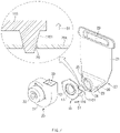
- FIG. 1 is a perspective view of an exemplary bell mouth 100 .
- FIG. 2 is a view illustrating an internal structure of a water-heating device according to an embodiment of the present disclosure.
- FIG. 3 is an exploded perspective view illustrating an air supply assembly and a blower 30 according to an embodiment of the present disclosure.
- the water-heating device may include a case 50 .
- Other components may be fixed in such a manner as to be embedded in or coupled to the case 50 .
- the case 50 may support the components of the water-heating device.
- Air may be introduced from the outside through an air supply duct 20 and may be delivered to a bell mouth 10 and the blower 30 , and the blower 30 may forcibly feed the air into a burner 81 .
- the exemplary bell mouth 100 may connect the blower 30 and the air supply duct 20 and may include a measurement portion 102 connected with a differential-pressure acquisition device 40 through a hose such that the differential-pressure acquisition device 40 obtains reduced pressure of air passing through an opening 101 of the bell mouth 100 .
- the differential-pressure acquisition device 40 in the exemplary water-heating device may obtain negative pressure generated in the bell mouth 100 and the pressure in the case 50 .
- a processor 70 may control the blower 30 and may control the flow rate of air supplied into the burner 81 .
- the blower 30 may not be appropriately controlled.
- this situation may occur in a water-heating device in which forced air-supply and exhaust and forced exhaust are mixed or selectively used.
- the pressure in the interior space 500 of the case 50 may remain equal to the atmospheric pressure, and in a situation in which the water-heating device is operated by the forced exhaust method, the pressure in the interior space 500 of the case 50 may be lower than the atmospheric pressure.
- the water-heating device may include the burner 81 , a heat exchanger 82 , the blower 30 , the bell mouth 10 , the differential-pressure acquisition device 40 , the air supply duct 20 , and the processor 70 .
- the processor 70 may control the blower 30 to deliver air to the burner 81 at a stable flow rate even in the situation in which the pressure in the case 50 changes.
- the air supply duct 20 may be a component through which air is introduced into the water-heating device from the outside.
- the air supply duct 20 connected with an air-supply and exhaust pipe 83 may guide the air into the water-heating device from the outside, and the air may be delivered to the burner 81 through the bell mouth 10 and the blower 30 .
- the air-supply and exhaust pipe 83 may be formed in the form of a double pipe to enable air supply and exhaust.
- the air introduced into the air supply duct 20 from above the water-heating device may flow downward through the air supply duct 20 and may be released from the air supply duct 20 through the bell mouth 10 .
- the air supply duct 20 may have a shape extending along an up-down direction and may have an empty space formed therein for delivering the air.
- the direction in which the air supply duct 20 extends is expressed as the up-down direction. However, this is illustrative, and the direction may be changed depending on a way in which the water-heating device is arranged.
- the air supply duct 20 may include a duct body 21 , a redirection portion 22 , and a stabilizing portion 23 .
- the air supply duct 20 may further include an air inlet 29 and an air outlet 25 .
- the components of the air supply duct 20 will be described below in detail with reference to FIG. 8 .
- the processor 70 may be electrically connected with the blower 30 and the differential-pressure acquisition device 40 and may control the blower 30 using a differential pressure value calculated from the pressure obtained by the differential-pressure acquisition device 40 .
- the processor 70 may include a microprocessor such as a field programmable gate array (FPGA), an application specific integrated circuit (ASIC), or a central processing unit (CPU).
- FPGA field programmable gate array
- ASIC application specific integrated circuit
- CPU central processing unit
- the type of a computing device included in the processor 70 is not limited thereto.
- the processor 70 may include a memory that stores a plurality of control instructions, on the basis of which the processor 70 generates commands for controlling the components.
- the processor 70 may be programmed to receive the control instructions from the memory and generate electrical signals for controlling the components, based on the received control instructions.
- the memory may be a data store such as a hard disk drive (HDD), a solid state drive (SSD), a volatile medium, a non-volatile medium, or the like.
- HDD hard disk drive
- SSD solid state drive
- volatile medium a non-volatile medium, or the like.
- the type of the memory is not limited thereto.
- the burner 81 may burn a fuel gas and the supplied air together. Heat and combustion gases may be generated by the combustion reaction.
- the heat exchanger 82 may transfer the heat generated by the combustion reaction in the burner 81 to heating water.
- the heat exchanger 82 may include a tube and a housing that forms an interior space in which the tube is received. While water flows through the tube, the combustion gases may flow around the tube, and the heat generated by the combustion reaction in the burner 81 may be transferred to the water to heat the water.
- the differential-pressure acquisition device 40 may obtain a differential pressure.
- the differential-pressure acquisition device 40 may be connected to the bell mouth 10 and may obtain a differential pressure of the air passing through the bell mouth 10 .
- the differential-pressure acquisition device 40 may be connected to an upstream measurement portion 111 and a downstream measurement portion 131 formed in the bell mouth 10 according to an embodiment of the present disclosure.
- the differential-pressure acquisition device 40 may obtain the pressure of the air in the upstream measurement portion 111 and the pressure of the air in the downstream measurement portion 131 and may transfer a differential pressure value in the form of an electrical signal to the processor 70 , or may transfer the obtained pressures to the processor 70 as electrical signals, such that the processor 70 calculates the differential pressure.
- the differential-pressure acquisition device 40 may be a device that obtains a differential pressure between two points using a diaphragm. However, a method for obtaining pressures or a differential pressure is not limited thereto.
- the blower 30 may forcibly feed the air introduced by the air supply duct 20 into the burner 81 .
- the blower 30 may be connected with the burner 81 , with an outlet 33 of a blower body 31 facing toward the burner 81 .
- the blower 30 may be connected with the air supply duct 20 through the bell mouth 10 .
- an air flow may be generated in the water-heating device.
- the blower 30 may include a drive part 32 , such as a motor, which generates a driving force using electric power.
- the blower 30 may forcibly feed the air using the driving force generated from the drive part 32 .
- FIG. 4 is a perspective view illustrating the bell mouth 10 according to an embodiment of the present disclosure.
- FIG. 5 is an exploded perspective view illustrating the bell mouth 10 according to an embodiment of the present disclosure.
- the bell mouth 10 may connect the air supply duct 20 and the blower 30 .
- the bell mouth 10 may include an upstream body 11 , a downstream body 13 , and a differential-pressure generation part 12 located between the upstream body 11 and the downstream body 13 .
- the upstream body 11 may be located on an upstream side of the bell mouth 10 with respect to a flow direction D 1 of the air.
- the flow direction D 1 in which the air flows in the upstream body 11 is abbreviated as the flow direction D 1 .
- the flow direction D 1 may be a direction perpendicular to the up-down direction.
- the upstream body 11 may be connected with the air supply duct 20 by making direct contact with the air supply duct 20 .
- the upstream body 11 may include an upstream-side opening 110 and the upstream measurement portion 111 .
- the air released from the air outlet 25 of the air supply duct 20 may pass through the upstream-side opening 110 .
- the upstream body 11 may include an annular upstream ring portion 112 that defines the upstream-side opening 110 and an upstream surrounding portion 113 protruding from the periphery of the upstream ring portion 112 along the flow direction D 1 .
- the upstream ring portion 112 may meet the air outlet 25 of the air supply duct 20 .
- the upstream-side opening 110 may be formed in a circular shape. Accordingly, the inner circumferential surface of the upstream ring portion 112 may be formed in a circular shape and may define the upstream-side opening 110 .
- the upstream measurement portion 111 may be a portion of the upstream body 11 that is connected to the differential-pressure acquisition device 40 .
- the upstream measurement portion 111 may protrude from the upstream ring portion 112 , and an opposite end of a hose, one end of which is connected to the differential-pressure acquisition device 40 , may be connected to the upstream measurement portion 111 . Accordingly, the upstream measurement portion 111 and the differential-pressure acquisition device 40 may be connected with each other through the hose.
- the upstream measurement portion 111 may extend from the upstream ring portion 112 in a direction across the flow direction D 1 .
- the air in the upstream-side opening 110 may be delivered to the differential-pressure acquisition device 40 , which is connected to the upstream measurement portion 111 , through a hole that is formed from the inner surface of the upstream ring portion 112 , which defines the upstream-side opening 110 , to a tip end of the upstream measurement portion 111 .
- the pressure in the upstream-side opening 110 may be used by the differential-pressure acquisition device 40 .
- the upstream measurement portion 111 may extend across the flow direction D 1 .
- the direction in which the upstream measurement portion 111 protrudes may be perpendicular to the flow direction D 1 .
- the upstream surrounding portion 113 may form an insertion space into which a downstream ring portion 132 is inserted.
- the upstream surrounding portion 113 may also be formed in an annular shape, and the outer surface of the downstream ring portion 132 may be formed in a cylindrical shape. Accordingly, the insertion space may be formed in a cylindrical shape.
- the upstream surrounding portion 113 may be open in the radial direction such that a measurement portion insertion hole 1131 is formed.
- the downstream measurement portion 131 may pass through the measurement portion insertion hole 1131 .
- the measurement portion insertion hole 1131 may be formed in the upstream surrounding portion 113 to correspond to the downstream measurement portion 131 of the downstream body 13 .
- the cross-sectional area of an inner profile in a section obtained by cutting the upstream surrounding portion 113 with a plane perpendicular to the flow direction D 1 may be larger than the cross-sectional area of the upstream-side opening 110 . Accordingly, when the downstream ring portion 132 is inserted into the insertion space, a surface of the upstream ring portion 112 that faces in the flow direction D 1 may prevent an additional movement of the downstream ring portion 132 in the opposite direction to the flow direction D 1 . Furthermore, the inner surface of the upstream surrounding portion 113 may prevent an escape of the downstream ring portion 132 in a direction perpendicular to the flow direction D 1 .
- the upstream body 11 may further include upstream coupling portions 114 .
- the upstream coupling portions 114 may protrude outward from the upstream surrounding portion 113 .
- the upstream coupling portions 114 may have holes to which fasteners are fastened, respectively.
- the upstream coupling portions 114 may cover downstream coupling portions 134 such that the holes of the upstream coupling portions 114 are aligned with holes of the downstream coupling portions 134 that will be described below. In this state, the fasteners may be fastened to the holes, and the upstream body 11 and the downstream body 13 may be combined with each other.
- the differential-pressure generation part 12 may have a structure that reduces the pressure of the air passing through the differential-pressure generation part 12 .
- the differential-pressure generation part 12 may be located downstream of the upstream body 11 and upstream of the downstream body 13 with respect to the flow direction D 1 of the air. Accordingly, the pressure downstream of the differential-pressure generation part 12 may be lower than the pressure upstream of the differential-pressure generation part 12 .
- the differential-pressure generation part 12 may include a differential-pressure opening 120 formed through the differential-pressure generation part 12 along the flow direction D 1 .
- the diameter of the differential-pressure opening 120 may be smaller than the diameter of the upstream-side opening 110 and the diameter of the downstream-side opening 130 that will be described below.
- the differential-pressure generation part 12 may be formed in a circular ring shape and may have the circular differential-pressure opening 120 in the center thereof.
- the differential-pressure generation part 12 may function as an orifice plate that causes a pressure change.
- the differential-pressure generation part 12 may be fixed between the upstream ring portion 112 and the downstream ring portion 132 as the downstream ring portion 132 is inserted into the insertion space.
- the upstream body 11 and the downstream body 13 may be fastened or combined with each other to fix the differential-pressure generation part 12 , thereby preventing an escape of the differential-pressure generation part 12 .
- the downstream body 13 may be located on a downstream side of the bell mouth 10 with respect to the flow direction D 1 of the air.
- the downstream body 13 may be connected with the blower 30 by making direct contact with the blower 30 .
- the downstream body 13 may include the downstream-side opening 130 and the downstream measurement portion 131 .
- the downstream-side opening 130 may be formed to allow the air passing through the differential-pressure generation part 12 to pass through.
- the air passing through the differential-pressure generation part 12 may pass through the downstream-side opening 130 .
- the downstream body 13 may include the annular downstream ring portion 132 that defines the downstream-side opening 130 .
- the downstream-side opening 130 may be formed in a circular shape. Accordingly, the inner circumferential surface of the downstream ring portion 132 may be formed in a circular shape and may define the downstream-side opening 130 .
- the upstream-side opening 110 may have a smaller diameter than the downstream-side opening 130 .
- the upstream-side opening 110 , the downstream-side opening 130 , and the differential-pressure opening 120 may form concentric circles.
- the downstream body 13 may further include downstream coupling portions 134 .
- the downstream coupling portions 134 may protrude outward from the downstream ring portion 132 and may have the holes to which the fasteners are fastened.
- the downstream coupling portions 134 may be combined with the upstream coupling portions 114 as described above.
- the downstream body 13 may further include a downstream plate 133 .
- the downstream plate 133 may be formed to surround the downstream ring portion 132 and may be disposed on the exterior of a tip end of the downstream ring portion 132 with respect to the flow direction D 1 .
- the downstream plate 133 may be attached to the blower 30 .
- the downstream measurement portion 131 may be a portion of the downstream body 13 that is connected to the differential-pressure acquisition device 40 .
- the downstream measurement portion 131 may protrude from the downstream ring portion 132 , and an opposite end of a hose, one end of which is connected to the differential-pressure acquisition device 40 , may be connected to the downstream measurement portion 131 . Accordingly, the downstream measurement portion 131 and the differential-pressure acquisition device 40 may be connected with each other through the hose.
- the differential-pressure acquisition device 40 may measure a differential pressure between the two measurement portions. As the upstream measurement portion 111 is connected to the upstream-side opening 110 and the downstream measurement portion 131 is connected to the downstream-side opening 130 , the differential-pressure acquisition device 40 may obtain the difference between the pressure in the upstream-side opening 110 and the pressure in the downstream-side opening 130 .
- the downstream measurement portion 131 may extend across the flow direction D 1 . Meanwhile, the direction in which the upstream measurement portion 111 extends may not be parallel to the direction in which the downstream measurement portion 131 extends.
- the downstream ring portion 132 may be inserted into the insertion space to fix the differential-pressure generation part 12 .
- the downstream ring portion 132 may be formed in an annular shape.
- the downstream ring portion 132 when inserted into the insertion space, may fix the differential-pressure generation part 12 and may allow the upstream-side opening 110 , the downstream-side opening 130 , and the differential-pressure opening 120 to be aligned with one another.
- An air supply control system of the water-heating device may include the blower 30 , the bell mouth 10 , the differential-pressure acquisition device 40 , and the processor 70 . Due to the shape of the bell mouth 10 and the connection relationship with the differential-pressure acquisition device 40 , the air supply control system according to the embodiment of the present disclosure may not use the pressure in the interior space 500 of the case 500 to calculate a differential pressure and may identify only a difference in pressure between the front and rear ends of the bell mouth 10 that the differential-pressure generation part forms. Accordingly, the blower 30 may be controlled irrespective of a change in the pressure in the interior space 500 of the case 50 . The blower 30 may operate to allow the differential pressure between the front and rear ends of the differential-pressure generation part 12 to remain constant, and thus the water-heating device may be smoothly operated.
- FIG. 6 is a view illustrating a form in which the upstream body 11 of the bell mouth 10 is coupled to the air supply duct 20 according to an embodiment of the present disclosure.
- FIG. 7 is a view illustrating a coupling structure between the upstream body 11 of the bell mouth 10 and the air supply duct 20 according to a modified example of the embodiment of the present disclosure.
- the upstream body 11 of the bell mouth 10 may include a plurality of bell mouth fixing portions 115 protruding outward from the upstream ring portion 112 .
- the bell mouth fixing portions 115 may be fixedly coupled to the air supply duct 20 .
- two bell mouth fixing portions 115 may be formed.
- the two bell mouth fixing portions 115 may be disposed to be spaced apart from each other at a predetermined interval.
- the bell mouth fixing portions 115 may each include a hole formed therein as illustrated.
- the bell mouth fixing portions 115 may be fixedly coupled to the air supply duct 20 by fasteners passing through the holes. Screws may be used as the fasteners. However, the fasteners are not limited thereto.
- the upstream body 11 may further include bell mouth fixing protrusions 1161 .
- Three bell mouth fixing protrusions 1161 may be formed on three fixing protrusion connecting portions 116 , respectively, so as to reach three points illustrated in FIG. 6 .
- the three fixing protrusion connecting portions 116 may protrude outward from the upstream ring portion 112 . As the three points are spaced apart from each other and the intervals therebetween are similarly maintained, the bell mouth 10 may be stably fixed to the air supply duct 20 with a small amount of eccentricity.
- the air supply duct 20 may further include coupling holes 26 formed in positions corresponding to the positions of the plurality of bell mouth fixing protrusions 1161 such that the bell mouth 10 is fixed to a predetermined position as the plurality of bell mouth fixing protrusions 1161 are inserted into the coupling holes 26 . Accordingly, as illustrated in FIG. 7 , as the upstream body 11 approaches the air supply duct 20 , the bell mouth fixing protrusions 1161 may be inserted into the coupling holes 26 , and the bell mouth 10 may be fixedly located in a predetermined position at a predetermined angle.
- FIG. 8 is a side view of the air supply duct 20 according to an embodiment of the present disclosure.
- Air may be introduced into the duct body 21 through the air inlet 29 of the air supply duct 20 .
- the air may be guided downward along the duct body 21 and may change the flow direction in the redirection portion 22 .
- the flow direction of the air may be changed to the horizontal direction in the redirection portion 22 .
- the air, the flow direction of which is changed in the redirection portion 22 may flow along the horizontal direction through the stabilizing portion 23 that extends from the redirection portion 22 along the flow direction D 1 .
- the air may be released to the upstream-side opening 110 of the bell mouth through the air outlet 25 surrounded and defined by a stabilizing portion tip end 24 formed at an end of the stabilizing portion 23 .
- the stabilizing portion tip end 24 may be formed in a circular ring shape.
- the stabilizing portion tip end 24 may have a stepped structure relative to the other part of the stabilizing portion 23 .
- the stabilizing portion tip end 24 may make contact with the bell mouth 10 .
- the air may flow downward through the duct body 21 , may change the flow direction while passing through the redirection portion 22 , and may flow through the stabilizing portion 23 in the flow direction D 1 parallel to the horizontal direction. Therefore, when the air is supplied into the bell mouth 10 and the blower 30 as soon as the flow direction of the air is changed, the differential-pressure acquisition device 40 may not be able to obtain a stable differential pressure value.
- This problem may be solved by making the length A 1 of the stabilizing portion 23 greater than the length B 1 of the redirection portion 22 with respect to the flow direction D 1 . As the air travels a predetermined distance without a change of direction, a differential pressure value may be stabilized.
- the bell mouth 10 according to the embodiment of the present disclosure may be combined with the above-described air supply duct 20 to form the air supply assembly, thereby providing a stable differential pressure value to the differential-pressure acquisition device 40 .
- FIG. 9 is a side view of an air supply duct 202 according to another embodiment of the present disclosure.
- the length A 2 of a stabilizing portion 232 may be smaller than the length B 2 of a redirection portion 222 with respect to the flow direction D 1 .
- FIG. 10 is a side view of an air supply duct 203 according to another embodiment of the present disclosure.
- the length A 3 of a stabilizing portion 233 may be two or more times greater than the length B 3 of a redirection portion 223 with respect to the flow direction D 1 .
- the length B 3 of the redirection portion 223 may be greater than the length of a cylindrical portion adjacent to a stabilizing portion tip end 243 .
- FIG. 11 is a view illustrating part of the inside of the air supply duct 20 according to an embodiment of the present disclosure.
- FIG. 12 is a view illustrating a guide part 27 disposed in the air supply duct 20 according to an embodiment of the present disclosure.
- a differential pressure value may be stabilized by adjusting the length of the stabilizing portion 23 .
- the air supply duct 20 may further include the guide part 27 .
- the guide part 27 may be disposed in the redirection portion 22 and may form a slope slighter than the slope of a lower end of the inner surface of the redirection portion 22 with respect to the vertical direction.
- the guide part 27 may be formed of a material having elasticity and may be formed to cover part of the inner surface of the redirection portion 22 .
- the guide part 27 may have guide fixing protrusions 272 that protrude in the opposite direction to the flow direction D 1 .
- the redirection portion 22 may have, in the inner surface thereof, insertion holes 281 into which the guide fixing protrusions 272 are inserted. As the guide fixing protrusions 272 are inserted into the insertion holes 281 , the guide part 27 may be fixed to the redirection portion 22 well.
- the air supply duct 20 may be formed in such a manner that a first plate 20 a and a second plate 20 b are pressed against each other, and an empty space between the first plate 20 a and the second plate 20 b spaced apart from each other may foil a passage through which air flows.
- the first plate 20 a may be a plate that faces in the flow direction D 1 relative to the second plate 20 b and on which the air outlet 25 and the stabilizing portion 23 are located.
- the redirection portion 22 may be located on the second plate 20 b.
- the integrated first plate 20 a may be formed such that the redirection portion 22 and part of the duct body 21 are connected with each other, and the integrated second plate 20 b may be foiled such that the stabilizing portion 23 and part of the duct body 21 are connected with each other.
- the guide part 27 may include a guide fixing portion 271 .
- the guide fixing portion 271 may be fixedly inserted into an insertion groove 28 formed by the first plate 20 a and the second plate 20 b spaced apart from each other. That is, the first plate 20 a and the second plate 20 b may be pressed against each other with the guide fixing portion 271 therebetween to fix the guide fixing portion 271 , thereby preventing an escape of the guide part 27 .
- the insertion holes 281 may be formed in part of the second plate 20 b that forms the insertion groove 28 , and the guide fixing protrusions 272 may be formed on the guide fixing portion 271 . Accordingly, the guide part 27 may be more firmly fixed to the first plate 20 a and the second plate 20 b.
- a pressing jig passing through the air outlet 25 may be used.
- the pressing jig may be formed in a three-dimensional shape having a cross-section corresponding to that of the air outlet 25 .
- the air outlet 25 may be formed in a circular shape, and therefore the pressing jig may be formed in a cylindrical shape.
- the pressing jig may serve as a guide that passes through the air outlet 25 and presses the second plate 20 b to prevent an escape of the guide part 27 in a process of pressing the guide part 27 toward the inside of the air supply duct 20 .
- the water-heating device may be stably operated by stably maintaining the flow rate of air supplied into the burner.
Landscapes
- Engineering & Computer Science (AREA)
- Mechanical Engineering (AREA)
- General Engineering & Computer Science (AREA)
- Chemical & Material Sciences (AREA)
- Combustion & Propulsion (AREA)
- Physics & Mathematics (AREA)
- Thermal Sciences (AREA)
- Fluid Mechanics (AREA)
- General Physics & Mathematics (AREA)
- Regulation And Control Of Combustion (AREA)
- Air Supply (AREA)
- Measuring Volume Flow (AREA)
Abstract
Description
Claims (13)
Applications Claiming Priority (2)
| Application Number | Priority Date | Filing Date | Title |
|---|---|---|---|
| KR10-2019-0113102 | 2019-09-11 | ||
| KR1020190113102A KR102403219B1 (en) | 2019-09-11 | 2019-09-11 | Bellmouth, air supply assembly includng the same and air supply control system using the same |
Publications (2)
| Publication Number | Publication Date |
|---|---|
| US20210071911A1 US20210071911A1 (en) | 2021-03-11 |
| US11408641B2 true US11408641B2 (en) | 2022-08-09 |
Family
ID=74849458
Family Applications (1)
| Application Number | Title | Priority Date | Filing Date |
|---|---|---|---|
| US17/013,103 Active US11408641B2 (en) | 2019-09-11 | 2020-09-04 | Bell mouth, air supply assembly including the bell mouth, and air supply control system using the bell mouth |
Country Status (3)
| Country | Link |
|---|---|
| US (1) | US11408641B2 (en) |
| KR (1) | KR102403219B1 (en) |
| AU (1) | AU2020223747B2 (en) |
Families Citing this family (1)
| Publication number | Priority date | Publication date | Assignee | Title |
|---|---|---|---|---|
| JP7759096B2 (en) * | 2022-03-07 | 2025-10-23 | 株式会社パロマ | water heater |
Citations (21)
| Publication number | Priority date | Publication date | Assignee | Title |
|---|---|---|---|---|
| US1419876A (en) * | 1920-04-07 | 1922-06-13 | Gen Electric | Flow tube |
| US1559156A (en) * | 1924-11-08 | 1925-10-27 | Gen Electric | Orifice-type pressure-difference-creating device for flow meters |
| US1850030A (en) * | 1929-12-14 | 1932-03-15 | William S Pardoe | Venturi meter |
| US2929248A (en) * | 1957-11-13 | 1960-03-22 | Bailey Meter Co | Flow meter |
| US4249164A (en) * | 1979-05-14 | 1981-02-03 | Tivy Vincent V | Flow meter |
| US4528847A (en) * | 1983-10-04 | 1985-07-16 | D. Halmi And Associates, Inc. | Flow metering device with recessed pressure taps |
| US20030097880A1 (en) * | 2001-11-29 | 2003-05-29 | Ciobanu Calin I. | Multi-stage variable orifice flow obstruction sensor |
| KR20040060126A (en) | 2002-12-30 | 2004-07-06 | 오상택 | Portable air flow meter for measuring the amount of air to be flowed out |
| US20080125916A1 (en) * | 2006-07-10 | 2008-05-29 | Daniel Measurement And Control, Inc. | Method and System of Validating Data Regarding Measured Hydrocarbon Flow |
| KR100870887B1 (en) | 2008-07-23 | 2008-11-27 | (주) 터보맥스 | Turbometer with bell-mouth inlet flow measurement means for air or gas |
| US20090084328A1 (en) * | 2007-10-01 | 2009-04-02 | Lyons Jeff L | Water heaters with combustion air inlet |
| US20090308332A1 (en) * | 2007-10-01 | 2009-12-17 | Tanbour Emadeddin Y | Water heater with forced draft air inlet |
| US20100154723A1 (en) * | 2006-03-20 | 2010-06-24 | Garrabrant Michael A | ULTRA LOW NOx WATER HEATER |
| US20110315905A1 (en) * | 2008-12-26 | 2011-12-29 | Fujikin Incorporated | Gasket type orifice and pressure type flow rate control apparatus for which the orifice is employed |
| WO2014182053A1 (en) | 2013-05-08 | 2014-11-13 | 주식회사 경동나비엔 | Apparatus for measuring differential pressure in air blower |
| JP2016020795A (en) | 2014-07-15 | 2016-02-04 | 三浦工業株式会社 | Boiler system |
| US20160084686A1 (en) * | 2013-07-23 | 2016-03-24 | Yokogawa Corporation Of America | Optimized techniques for generating and measuring toroidal vortices via an industrial vortex flowmeter |
| US9329065B2 (en) * | 2014-07-25 | 2016-05-03 | General Electric Company | Variable orifice flow sensor utilizing localized contact force |
| US20180172519A1 (en) * | 2016-12-21 | 2018-06-21 | Ashcroft, Inc. | Mounting flange for measuring devices |
| KR101932992B1 (en) | 2017-09-01 | 2018-12-27 | 린나이코리아 주식회사 | Gas boiler have ventilation duct prevention water inflow |
| US20190219470A1 (en) * | 2018-01-16 | 2019-07-18 | Kyungdong Navien Co., Ltd. | Airflow sensor |
-
2019
- 2019-09-11 KR KR1020190113102A patent/KR102403219B1/en active Active
-
2020
- 2020-08-28 AU AU2020223747A patent/AU2020223747B2/en active Active
- 2020-09-04 US US17/013,103 patent/US11408641B2/en active Active
Patent Citations (21)
| Publication number | Priority date | Publication date | Assignee | Title |
|---|---|---|---|---|
| US1419876A (en) * | 1920-04-07 | 1922-06-13 | Gen Electric | Flow tube |
| US1559156A (en) * | 1924-11-08 | 1925-10-27 | Gen Electric | Orifice-type pressure-difference-creating device for flow meters |
| US1850030A (en) * | 1929-12-14 | 1932-03-15 | William S Pardoe | Venturi meter |
| US2929248A (en) * | 1957-11-13 | 1960-03-22 | Bailey Meter Co | Flow meter |
| US4249164A (en) * | 1979-05-14 | 1981-02-03 | Tivy Vincent V | Flow meter |
| US4528847A (en) * | 1983-10-04 | 1985-07-16 | D. Halmi And Associates, Inc. | Flow metering device with recessed pressure taps |
| US20030097880A1 (en) * | 2001-11-29 | 2003-05-29 | Ciobanu Calin I. | Multi-stage variable orifice flow obstruction sensor |
| KR20040060126A (en) | 2002-12-30 | 2004-07-06 | 오상택 | Portable air flow meter for measuring the amount of air to be flowed out |
| US20100154723A1 (en) * | 2006-03-20 | 2010-06-24 | Garrabrant Michael A | ULTRA LOW NOx WATER HEATER |
| US20080125916A1 (en) * | 2006-07-10 | 2008-05-29 | Daniel Measurement And Control, Inc. | Method and System of Validating Data Regarding Measured Hydrocarbon Flow |
| US20090084328A1 (en) * | 2007-10-01 | 2009-04-02 | Lyons Jeff L | Water heaters with combustion air inlet |
| US20090308332A1 (en) * | 2007-10-01 | 2009-12-17 | Tanbour Emadeddin Y | Water heater with forced draft air inlet |
| KR100870887B1 (en) | 2008-07-23 | 2008-11-27 | (주) 터보맥스 | Turbometer with bell-mouth inlet flow measurement means for air or gas |
| US20110315905A1 (en) * | 2008-12-26 | 2011-12-29 | Fujikin Incorporated | Gasket type orifice and pressure type flow rate control apparatus for which the orifice is employed |
| WO2014182053A1 (en) | 2013-05-08 | 2014-11-13 | 주식회사 경동나비엔 | Apparatus for measuring differential pressure in air blower |
| US20160084686A1 (en) * | 2013-07-23 | 2016-03-24 | Yokogawa Corporation Of America | Optimized techniques for generating and measuring toroidal vortices via an industrial vortex flowmeter |
| JP2016020795A (en) | 2014-07-15 | 2016-02-04 | 三浦工業株式会社 | Boiler system |
| US9329065B2 (en) * | 2014-07-25 | 2016-05-03 | General Electric Company | Variable orifice flow sensor utilizing localized contact force |
| US20180172519A1 (en) * | 2016-12-21 | 2018-06-21 | Ashcroft, Inc. | Mounting flange for measuring devices |
| KR101932992B1 (en) | 2017-09-01 | 2018-12-27 | 린나이코리아 주식회사 | Gas boiler have ventilation duct prevention water inflow |
| US20190219470A1 (en) * | 2018-01-16 | 2019-07-18 | Kyungdong Navien Co., Ltd. | Airflow sensor |
Non-Patent Citations (2)
| Title |
|---|
| First Examination Report for corresponding Australian Patent Application No. 2020223747, dated Sep. 2, 2021, 5 pages long. |
| First Office Action for Korean Patent Application No. 10-2019-0113102 dated Oct. 18, 2021, 8 pages long. |
Also Published As
| Publication number | Publication date |
|---|---|
| US20210071911A1 (en) | 2021-03-11 |
| KR102403219B1 (en) | 2022-05-30 |
| AU2020223747A1 (en) | 2021-03-25 |
| KR20210031313A (en) | 2021-03-19 |
| AU2020223747B2 (en) | 2022-05-19 |
Similar Documents
| Publication | Publication Date | Title |
|---|---|---|
| KR101702733B1 (en) | Exhaust gas feed device for an internal combustion engine | |
| CN108139073B (en) | The gas burner with multiple flame rings for cooking stove | |
| CA2830249C (en) | Burner assembly for a heating furnace | |
| AU2015363856A1 (en) | Hot water supply apparatus provided with pressure reducing valve | |
| KR20230020487A (en) | Aerosol generating device | |
| US11408641B2 (en) | Bell mouth, air supply assembly including the bell mouth, and air supply control system using the bell mouth | |
| US10281351B2 (en) | Water heater and pressure probe for a water heater | |
| CN110805503A (en) | Ramjet engine with rotary detonation combustion system and method of operation | |
| CA3052376C (en) | Vehicle heater | |
| CN111381609A (en) | Fluid control device | |
| US8245688B2 (en) | Intake system for internal combustion engine | |
| CN110779015B (en) | Venturi nozzle and fuel supply device provided with same | |
| CN212390365U (en) | Gas premixing device and gas water heater with same | |
| KR101413476B1 (en) | Air-heater | |
| CN109682237B (en) | A heater simulation device and a heater simulation system | |
| CN113531533B (en) | Gas premixing device and gas water heater with same | |
| CN223649306U (en) | Gas premixer and gas-fired hot water equipment | |
| US20250060094A1 (en) | Burner for a heater | |
| CN222230846U (en) | Air guide piece and vertical air conditioner with same | |
| CN223318425U (en) | A sealing ring mechanism with an air guide structure | |
| CN223035681U (en) | Flow control valve and water heater | |
| EP4067743B1 (en) | Venturi-type mixing nozzle and combustion device with a venturi-type mixing nozzle | |
| CN114198747B (en) | a burner | |
| CN214536828U (en) | Water heating device | |
| CN110341435B (en) | Air blower for combustion |
Legal Events
| Date | Code | Title | Description |
|---|---|---|---|
| FEPP | Fee payment procedure |
Free format text: ENTITY STATUS SET TO UNDISCOUNTED (ORIGINAL EVENT CODE: BIG.); ENTITY STATUS OF PATENT OWNER: LARGE ENTITY |
|
| AS | Assignment |
Owner name: KYUNGDONG NAVIEN CO.,LTD, KOREA, REPUBLIC OF Free format text: ASSIGNMENT OF ASSIGNORS INTEREST;ASSIGNORS:PARK, JUN KYU;HUR, JEON;YU, JEONG GI;SIGNING DATES FROM 20200827 TO 20200828;REEL/FRAME:053820/0545 |
|
| STPP | Information on status: patent application and granting procedure in general |
Free format text: DOCKETED NEW CASE - READY FOR EXAMINATION |
|
| STPP | Information on status: patent application and granting procedure in general |
Free format text: NON FINAL ACTION MAILED |
|
| STPP | Information on status: patent application and granting procedure in general |
Free format text: RESPONSE TO NON-FINAL OFFICE ACTION ENTERED AND FORWARDED TO EXAMINER |
|
| STPP | Information on status: patent application and granting procedure in general |
Free format text: NOTICE OF ALLOWANCE MAILED -- APPLICATION RECEIVED IN OFFICE OF PUBLICATIONS |
|
| STPP | Information on status: patent application and granting procedure in general |
Free format text: AWAITING TC RESP., ISSUE FEE NOT PAID |
|
| STPP | Information on status: patent application and granting procedure in general |
Free format text: NOTICE OF ALLOWANCE MAILED -- APPLICATION RECEIVED IN OFFICE OF PUBLICATIONS |
|
| STPP | Information on status: patent application and granting procedure in general |
Free format text: NOTICE OF ALLOWANCE MAILED -- APPLICATION RECEIVED IN OFFICE OF PUBLICATIONS |
|
| STCF | Information on status: patent grant |
Free format text: PATENTED CASE |
|
| MAFP | Maintenance fee payment |
Free format text: PAYMENT OF MAINTENANCE FEE, 4TH YEAR, LARGE ENTITY (ORIGINAL EVENT CODE: M1551); ENTITY STATUS OF PATENT OWNER: LARGE ENTITY Year of fee payment: 4 |