US11407372B2 - Airbag flap - Google Patents
Airbag flap Download PDFInfo
- Publication number
- US11407372B2 US11407372B2 US16/643,869 US201916643869A US11407372B2 US 11407372 B2 US11407372 B2 US 11407372B2 US 201916643869 A US201916643869 A US 201916643869A US 11407372 B2 US11407372 B2 US 11407372B2
- Authority
- US
- United States
- Prior art keywords
- airbag
- flap
- hinge element
- support wall
- receptacle
- Prior art date
- Legal status (The legal status is an assumption and is not a legal conclusion. Google has not performed a legal analysis and makes no representation as to the accuracy of the status listed.)
- Active
Links
Images


Classifications
-
- B—PERFORMING OPERATIONS; TRANSPORTING
- B60—VEHICLES IN GENERAL
- B60R—VEHICLES, VEHICLE FITTINGS, OR VEHICLE PARTS, NOT OTHERWISE PROVIDED FOR
- B60R21/00—Arrangements or fittings on vehicles for protecting or preventing injuries to occupants or pedestrians in case of accidents or other traffic risks
- B60R21/02—Occupant safety arrangements or fittings, e.g. crash pads
- B60R21/16—Inflatable occupant restraints or confinements designed to inflate upon impact or impending impact, e.g. air bags
- B60R21/20—Arrangements for storing inflatable members in their non-use or deflated condition; Arrangement or mounting of air bag modules or components
- B60R21/215—Arrangements for storing inflatable members in their non-use or deflated condition; Arrangement or mounting of air bag modules or components characterised by the covers for the inflatable member
- B60R2021/21537—Arrangements for storing inflatable members in their non-use or deflated condition; Arrangement or mounting of air bag modules or components characterised by the covers for the inflatable member characterised by hinges
Definitions
- the invention relates to an airbag flap covering the mouth of an airbag receptacle.
- An airbag outer cover typically overlies the airbag flap, and the airbag flap is connected in an integral manner by a hinge element to a flap support wall fastened to the airbag outer cover and/or to a wall of the receptacle, the airbag flap and the flap support wall consisting of the same flat plastic, in particular composite material.
- An airbag assembly of this kind is known from EP 2 727 775 [US 2014/0117649].
- the airbag flap is connected to the flap support wall extending into the receptacle, by a fold, in order to provide an additional path for the airbag flap when the airbag cushion emerges through the airbag mouth.
- the object of the invention is to provide a path-clearing technique for an airbag flap that is simple in terms of design and production, and requires little space.
- a yield structure in the form of a plurality of slots and/or openings is provided in the region of the hinge element and/or to one or both sides of the hinge element, in the flat plastic, in particular in the composite material, and as a result provides at least one stretch region in the material, in the direction in which the airbag flap is moved outward by the airbag cushion.
- the slots or openings are punchouts, cuts or punched cuts.
- the slots and/or openings made in the flat plastic in the region of or close to the hinge element of the airbag flap render the flat material stretchable when tensile forces act on the airbag flap when the airbag cushion deploys.
- the flat material is therefore in the cut/stamped state as long as the airbag is not triggered. Only after triggering of the airbag does the material stretch in a path-clearing manner to form openings.
- the cut/stamped flat material it is particularly advantageous for the cut/stamped flat material to have small outside dimensions in the unstretched state, and thus to be space-saving. It is also simple and cost-effective to make.
- the type, orientation, density and size of the slots and/or openings make it possible to exactly determine what additional distance(s) should be provided at what forces. Stretching the yield structure results in a grid structure, in particular with lozenge-shaped holes.
- the airbag flap and the flap support wall consist of a composite material comprising at least one layer of plastic tapes or fibers, in particular consisting of thermoplastic polypropylene or polyester, and at least one plastic layer melted thereon.
- the plastic tapes or fibers can form a woven fabric.
- FIG. 1 is a cross section through an airbag unit
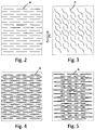
- FIGS. 2 to 5 are views of the yield structure in the viewing direction according to the arrow A and B in FIG. 1 when not stretched.
- the airbag assembly comprises a receptacle 12 that receives an airbag 7 , is surrounded by walls 9 , and is closed by a cover 2 that has the predetermined breakaway lines 2 a .
- the cover 2 forms an airbag mouth when, after the airbag 7 has been triggered, the cover 2 ruptures at the predetermined breakaway lines and folds outward.
- the flap formed by the cover 2 is fastened to the remaining cover by an edge that forms a hinge 11 .
- the cover 2 is externally covered by a foam layer 5 on whose outer face a decorative surface material 6 is laid.
- At least one airbag flap 1 is fastened to the lower face of the cover 2 that is molded onto the airbag flap 1 .
- the material of the airbag flap 1 and the production method are described in EP 2 727 775.
- the airbag mouth is closed by a single airbag flap 1 that comprises the hinge element 11 .
- two airbag flaps may be provided with hinge elements on opposite sides.
- the airbag flap(s) is/are in each case integrally formed on a flap support wall 4 by the hinge element 11 , which flap support wall extends into the interior of the receptacle 12 .
- the flap support wall 4 is fastened to the inner surface of the receptacle wall 9 .
- the airbag flap 1 and/or the flap support wall 4 integrally molded onto the airbag flaps comprises/comprise at least one horizontal structure S 1 and/or S 2 , in the flat plastic, in particular in the composite material, close to the hinge/hinge element 11 and/or in the hinge region.
- cuts a and/or openings/holes b are cut or stamped, in a regular arrangement and at regular spacings, in the flat material of the airbag flaps 1 and/or of the flap support wall 4 and/or in the region of the hinge 11 , as is shown for example in FIG. 2 to 5 , in the unstretched state.
- the airbag unit pushes against the airbag flap(s) that pivots/pivot outwards, tensile forces arising on the airbag flap(s) and often also on the flap support wall 4 , in the surface plane, in the arrow direction C, which forces stretch the material in the direction C, extension of the material in the arrow direction C being made possible by the cuts a spreading to form openings, and the openings/holes b enlarging to form a grid structure, in particular with lozenge-shaped holes, resulting in the plastic, in particular in the plastic composite material.
- the airbag flap 1 and the flap support wall 4 consist of composite material comprising at least one layer of plastic tapes or fibers, in particular consisting of thermoplastic polypropylene or polyester, and at least one plastic layer melted thereon.
- the plastic tapes or fibers form a woven fabric.
Landscapes
- Engineering & Computer Science (AREA)
- Mechanical Engineering (AREA)
- Air Bags (AREA)
- Laminated Bodies (AREA)
Abstract
Description
Claims (6)
Applications Claiming Priority (3)
| Application Number | Priority Date | Filing Date | Title |
|---|---|---|---|
| DE102018006704.2A DE102018006704A1 (en) | 2018-08-24 | 2018-08-24 | airbag flap |
| DE102018006704.2 | 2018-08-24 | ||
| PCT/EP2019/000153 WO2020038596A1 (en) | 2018-08-24 | 2019-05-17 | Airbag flap |
Publications (2)
| Publication Number | Publication Date |
|---|---|
| US20210354651A1 US20210354651A1 (en) | 2021-11-18 |
| US11407372B2 true US11407372B2 (en) | 2022-08-09 |
Family
ID=66752038
Family Applications (1)
| Application Number | Title | Priority Date | Filing Date |
|---|---|---|---|
| US16/643,869 Active US11407372B2 (en) | 2018-08-24 | 2019-05-17 | Airbag flap |
Country Status (6)
| Country | Link |
|---|---|
| US (1) | US11407372B2 (en) |
| EP (1) | EP3684654B1 (en) |
| CN (1) | CN111295312B (en) |
| DE (1) | DE102018006704A1 (en) |
| MX (1) | MX2020004393A (en) |
| WO (1) | WO2020038596A1 (en) |
Cited By (1)
| Publication number | Priority date | Publication date | Assignee | Title |
|---|---|---|---|---|
| US12257970B1 (en) | 2024-05-22 | 2025-03-25 | Faurecia Interior Systems, Inc. | Vehicle interior panel with folded hinge layer |
Families Citing this family (3)
| Publication number | Priority date | Publication date | Assignee | Title |
|---|---|---|---|---|
| DE102018006703A1 (en) * | 2018-08-24 | 2020-02-27 | K.L. Kaschier- Und Laminier Gmbh | An air bag assembly |
| DE102018006704A1 (en) * | 2018-08-24 | 2020-02-27 | K.L. Kaschier- Und Laminier Gmbh | airbag flap |
| DE102021124189A1 (en) * | 2021-09-20 | 2023-03-23 | K. L. Kaschier- Und Laminier Gmbh | Textile surface element of an airbag |
Citations (13)
| Publication number | Priority date | Publication date | Assignee | Title |
|---|---|---|---|---|
| DE10352566A1 (en) * | 2003-11-11 | 2005-06-09 | Bayerische Motoren Werke Ag | Airbag unit, comprising upper decorative textile layer of cover provided with pre-damaged threads or thinner threads |
| DE102004010643A1 (en) | 2004-03-01 | 2005-10-06 | Faurecia Innenraum Systeme Gmbh | Trim section with airbag flap section in motor vehicle has flexible flat element fastened outside airbag flap section so that part of it lying outside trim section and forming hinge there has overlength |
| US20100078920A1 (en) * | 2008-09-29 | 2010-04-01 | Toyoda Gosei Co., Ltd. | Air bag door |
| US8348303B1 (en) | 2007-02-21 | 2013-01-08 | K.L. Kaschier-Und Laminier Gmbh | Airbag cover hinge with force-absorbing system |
| US20140120285A1 (en) * | 2012-10-31 | 2014-05-01 | Maik HOEING | Airbag cover with at least one flap |
| US20140117649A1 (en) | 2012-10-31 | 2014-05-01 | Maik HOEING | Airbag cover with at least one flap |
| WO2015139803A1 (en) * | 2014-03-20 | 2015-09-24 | K.L. Kaschier- Und Laminier Gmbh | Airbag cover hinge with pressure-sensing system |
| DE102015010643A1 (en) | 2014-08-18 | 2016-02-18 | Zbigniew Fidyka | transmission device |
| US20180001858A1 (en) * | 2015-01-30 | 2018-01-04 | K.L. Kaschier-Und Laminier Gmbh | Composite material for an airbag cover |
| US20180099633A1 (en) * | 2016-10-06 | 2018-04-12 | Hyundai Motor Company | Hinge Device for Airbag Door of Vehicle |
| WO2020038594A1 (en) * | 2018-08-24 | 2020-02-27 | K.L. Kaschier- Und Laminier Gmbh | Covering assembly of an airbag |
| CN111295312A (en) * | 2018-08-24 | 2020-06-16 | K.L.复合和层压有限公司 | Air bag cover |
| US20210016738A1 (en) * | 2019-07-15 | 2021-01-21 | Hyundai Motor Company | Hinge structure for air bag door |
Family Cites Families (1)
| Publication number | Priority date | Publication date | Assignee | Title |
|---|---|---|---|---|
| CN115257074A (en) * | 2017-09-22 | 2022-11-01 | 苏州圣远成汽车附件股份有限公司 | Composite material for automobile safety airbag cover |
-
2018
- 2018-08-24 DE DE102018006704.2A patent/DE102018006704A1/en active Pending
-
2019
- 2019-05-17 US US16/643,869 patent/US11407372B2/en active Active
- 2019-05-17 EP EP19728316.1A patent/EP3684654B1/en active Active
- 2019-05-17 MX MX2020004393A patent/MX2020004393A/en unknown
- 2019-05-17 WO PCT/EP2019/000153 patent/WO2020038596A1/en not_active Ceased
- 2019-05-17 CN CN201980005467.6A patent/CN111295312B/en active Active
Patent Citations (15)
| Publication number | Priority date | Publication date | Assignee | Title |
|---|---|---|---|---|
| DE10352566A1 (en) * | 2003-11-11 | 2005-06-09 | Bayerische Motoren Werke Ag | Airbag unit, comprising upper decorative textile layer of cover provided with pre-damaged threads or thinner threads |
| DE102004010643A1 (en) | 2004-03-01 | 2005-10-06 | Faurecia Innenraum Systeme Gmbh | Trim section with airbag flap section in motor vehicle has flexible flat element fastened outside airbag flap section so that part of it lying outside trim section and forming hinge there has overlength |
| US8348303B1 (en) | 2007-02-21 | 2013-01-08 | K.L. Kaschier-Und Laminier Gmbh | Airbag cover hinge with force-absorbing system |
| US20100078920A1 (en) * | 2008-09-29 | 2010-04-01 | Toyoda Gosei Co., Ltd. | Air bag door |
| US20140120285A1 (en) * | 2012-10-31 | 2014-05-01 | Maik HOEING | Airbag cover with at least one flap |
| US20140117649A1 (en) | 2012-10-31 | 2014-05-01 | Maik HOEING | Airbag cover with at least one flap |
| US20160023625A1 (en) | 2013-03-20 | 2016-01-28 | K.L. Kaschier- Und Laminier Gmbh | Airbag cover hinge with pressure-sensing system |
| WO2015139803A1 (en) * | 2014-03-20 | 2015-09-24 | K.L. Kaschier- Und Laminier Gmbh | Airbag cover hinge with pressure-sensing system |
| DE102015010643A1 (en) | 2014-08-18 | 2016-02-18 | Zbigniew Fidyka | transmission device |
| US20180001858A1 (en) * | 2015-01-30 | 2018-01-04 | K.L. Kaschier-Und Laminier Gmbh | Composite material for an airbag cover |
| US20180099633A1 (en) * | 2016-10-06 | 2018-04-12 | Hyundai Motor Company | Hinge Device for Airbag Door of Vehicle |
| US10160415B2 (en) | 2016-10-06 | 2018-12-25 | Hyundai Motor Company | Hinge device for airbag door of vehicle |
| WO2020038594A1 (en) * | 2018-08-24 | 2020-02-27 | K.L. Kaschier- Und Laminier Gmbh | Covering assembly of an airbag |
| CN111295312A (en) * | 2018-08-24 | 2020-06-16 | K.L.复合和层压有限公司 | Air bag cover |
| US20210016738A1 (en) * | 2019-07-15 | 2021-01-21 | Hyundai Motor Company | Hinge structure for air bag door |
Cited By (1)
| Publication number | Priority date | Publication date | Assignee | Title |
|---|---|---|---|---|
| US12257970B1 (en) | 2024-05-22 | 2025-03-25 | Faurecia Interior Systems, Inc. | Vehicle interior panel with folded hinge layer |
Also Published As
| Publication number | Publication date |
|---|---|
| EP3684654B1 (en) | 2026-04-29 |
| US20210354651A1 (en) | 2021-11-18 |
| MX2020004393A (en) | 2020-09-25 |
| DE102018006704A1 (en) | 2020-02-27 |
| EP3684654A1 (en) | 2020-07-29 |
| CN111295312B (en) | 2023-07-07 |
| CN111295312A (en) | 2020-06-16 |
| WO2020038596A1 (en) | 2020-02-27 |
Similar Documents
| Publication | Publication Date | Title |
|---|---|---|
| US11407372B2 (en) | Airbag flap | |
| US8403357B2 (en) | Passenger air-bag door | |
| CN204196839U (en) | Airbag apparatus | |
| KR930017756A (en) | Device for guiding the development of a safety cushion in a car | |
| US7422233B2 (en) | Air-bag | |
| US9975514B1 (en) | Automotive air bag chute door hinge with variable extension | |
| US8567814B2 (en) | Patterned weakening of airbag coverings | |
| CN105452065B (en) | Vehicle seat and method of manufacturing the vehicle seat | |
| US7216892B2 (en) | Air bag door and attachment method | |
| US7753401B2 (en) | Flexible airbag case | |
| US20150054268A1 (en) | Active bolster with integrated vent | |
| CN208469732U (en) | Airbag doors for vehicles | |
| CN107428303A (en) | Curtain airbag | |
| US20190359165A1 (en) | Side air bag device | |
| US20210370862A1 (en) | Airbag cover | |
| CN111448105A (en) | Airbag module | |
| EP2460696A1 (en) | Improved tear seams for airbag covers | |
| CN103029671A (en) | Vehicle seat assembly with rigid air bag protection member | |
| CN111731219B (en) | Knee airbag device | |
| US5312130A (en) | Lid of an air bag device for use in a passenger's seat | |
| HK40022396A (en) | Airbag flap | |
| KR102661046B1 (en) | Side airbag apparatus and manufacturing method thereof | |
| HK40022396B (en) | Airbag flap | |
| US10569734B2 (en) | Passenger airbag chute channel with radial rib pattern | |
| CN103029670A (en) | Vehicle seat assembly with air bag module having integral protection member |
Legal Events
| Date | Code | Title | Description |
|---|---|---|---|
| FEPP | Fee payment procedure |
Free format text: ENTITY STATUS SET TO UNDISCOUNTED (ORIGINAL EVENT CODE: BIG.); ENTITY STATUS OF PATENT OWNER: SMALL ENTITY |
|
| FEPP | Fee payment procedure |
Free format text: ENTITY STATUS SET TO SMALL (ORIGINAL EVENT CODE: SMAL); ENTITY STATUS OF PATENT OWNER: SMALL ENTITY |
|
| AS | Assignment |
Owner name: K.L. KASCHIER-UND LAMINIER GMBH, GERMANY Free format text: ASSIGNMENT OF ASSIGNORS INTEREST;ASSIGNORS:WEHNINCK, REMBERT SCHULZE;RORING, ALBERT;REEL/FRAME:052151/0482 Effective date: 20200311 |
|
| STPP | Information on status: patent application and granting procedure in general |
Free format text: NON FINAL ACTION MAILED |
|
| STPP | Information on status: patent application and granting procedure in general |
Free format text: RESPONSE TO NON-FINAL OFFICE ACTION ENTERED AND FORWARDED TO EXAMINER |
|
| STPP | Information on status: patent application and granting procedure in general |
Free format text: NOTICE OF ALLOWANCE MAILED -- APPLICATION RECEIVED IN OFFICE OF PUBLICATIONS |
|
| STCF | Information on status: patent grant |
Free format text: PATENTED CASE |
|
| MAFP | Maintenance fee payment |
Free format text: PAYMENT OF MAINTENANCE FEE, 4TH YR, SMALL ENTITY (ORIGINAL EVENT CODE: M2551); ENTITY STATUS OF PATENT OWNER: SMALL ENTITY Year of fee payment: 4 |