US11407115B2 - Work robot system - Google Patents
Work robot system Download PDFInfo
- Publication number
- US11407115B2 US11407115B2 US16/245,593 US201916245593A US11407115B2 US 11407115 B2 US11407115 B2 US 11407115B2 US 201916245593 A US201916245593 A US 201916245593A US 11407115 B2 US11407115 B2 US 11407115B2
- Authority
- US
- United States
- Prior art keywords
- robot
- controller
- sensor
- target portion
- conveying apparatus
- Prior art date
- Legal status (The legal status is an assumption and is not a legal conclusion. Google has not performed a legal analysis and makes no representation as to the accuracy of the status listed.)
- Active, expires
Links
- 238000001514 detection method Methods 0.000 claims abstract description 65
- 230000005856 abnormality Effects 0.000 claims description 11
- 230000000007 visual effect Effects 0.000 claims 8
- 230000002265 prevention Effects 0.000 description 6
- 238000004904 shortening Methods 0.000 description 6
- 238000003860 storage Methods 0.000 description 6
- 230000000694 effects Effects 0.000 description 5
- 230000002708 enhancing effect Effects 0.000 description 5
- 230000010355 oscillation Effects 0.000 description 5
- 230000035945 sensitivity Effects 0.000 description 5
- 238000000034 method Methods 0.000 description 4
- 238000010586 diagram Methods 0.000 description 3
- 210000000078 claw Anatomy 0.000 description 2
- 230000007547 defect Effects 0.000 description 2
- 230000005484 gravity Effects 0.000 description 2
- 238000007689 inspection Methods 0.000 description 2
- 238000004519 manufacturing process Methods 0.000 description 2
- 238000005498 polishing Methods 0.000 description 2
- 210000000707 wrist Anatomy 0.000 description 2
- 238000012935 Averaging Methods 0.000 description 1
- 230000002159 abnormal effect Effects 0.000 description 1
- 230000006866 deterioration Effects 0.000 description 1
- 238000003801 milling Methods 0.000 description 1
- 230000004043 responsiveness Effects 0.000 description 1
- 238000004804 winding Methods 0.000 description 1
Images


Classifications
-
- B—PERFORMING OPERATIONS; TRANSPORTING
- B25—HAND TOOLS; PORTABLE POWER-DRIVEN TOOLS; MANIPULATORS
- B25J—MANIPULATORS; CHAMBERS PROVIDED WITH MANIPULATION DEVICES
- B25J9/00—Programme-controlled manipulators
- B25J9/16—Programme controls
- B25J9/1694—Programme controls characterised by use of sensors other than normal servo-feedback from position, speed or acceleration sensors, perception control, multi-sensor controlled systems, sensor fusion
- B25J9/1697—Vision controlled systems
-
- B—PERFORMING OPERATIONS; TRANSPORTING
- B25—HAND TOOLS; PORTABLE POWER-DRIVEN TOOLS; MANIPULATORS
- B25J—MANIPULATORS; CHAMBERS PROVIDED WITH MANIPULATION DEVICES
- B25J9/00—Programme-controlled manipulators
-
- B—PERFORMING OPERATIONS; TRANSPORTING
- B25—HAND TOOLS; PORTABLE POWER-DRIVEN TOOLS; MANIPULATORS
- B25J—MANIPULATORS; CHAMBERS PROVIDED WITH MANIPULATION DEVICES
- B25J13/00—Controls for manipulators
- B25J13/08—Controls for manipulators by means of sensing devices, e.g. viewing or touching devices
- B25J13/085—Force or torque sensors
-
- B—PERFORMING OPERATIONS; TRANSPORTING
- B25—HAND TOOLS; PORTABLE POWER-DRIVEN TOOLS; MANIPULATORS
- B25J—MANIPULATORS; CHAMBERS PROVIDED WITH MANIPULATION DEVICES
- B25J19/00—Accessories fitted to manipulators, e.g. for monitoring, for viewing; Safety devices combined with or specially adapted for use in connection with manipulators
- B25J19/02—Sensing devices
- B25J19/021—Optical sensing devices
- B25J19/023—Optical sensing devices including video camera means
-
- B—PERFORMING OPERATIONS; TRANSPORTING
- B25—HAND TOOLS; PORTABLE POWER-DRIVEN TOOLS; MANIPULATORS
- B25J—MANIPULATORS; CHAMBERS PROVIDED WITH MANIPULATION DEVICES
- B25J9/00—Programme-controlled manipulators
- B25J9/0093—Programme-controlled manipulators co-operating with conveyor means
-
- B—PERFORMING OPERATIONS; TRANSPORTING
- B25—HAND TOOLS; PORTABLE POWER-DRIVEN TOOLS; MANIPULATORS
- B25J—MANIPULATORS; CHAMBERS PROVIDED WITH MANIPULATION DEVICES
- B25J9/00—Programme-controlled manipulators
- B25J9/16—Programme controls
- B25J9/1628—Programme controls characterised by the control loop
- B25J9/1633—Programme controls characterised by the control loop compliant, force, torque control, e.g. combined with position control
-
- B—PERFORMING OPERATIONS; TRANSPORTING
- B25—HAND TOOLS; PORTABLE POWER-DRIVEN TOOLS; MANIPULATORS
- B25J—MANIPULATORS; CHAMBERS PROVIDED WITH MANIPULATION DEVICES
- B25J9/00—Programme-controlled manipulators
- B25J9/16—Programme controls
- B25J9/1679—Programme controls characterised by the tasks executed
-
- G—PHYSICS
- G05—CONTROLLING; REGULATING
- G05B—CONTROL OR REGULATING SYSTEMS IN GENERAL; FUNCTIONAL ELEMENTS OF SUCH SYSTEMS; MONITORING OR TESTING ARRANGEMENTS FOR SUCH SYSTEMS OR ELEMENTS
- G05B19/00—Programme-control systems
- G05B19/02—Programme-control systems electric
- G05B19/18—Numerical control [NC], i.e. automatically operating machines, in particular machine tools, e.g. in a manufacturing environment, so as to execute positioning, movement or co-ordinated operations by means of programme data in numerical form
- G05B19/19—Numerical control [NC], i.e. automatically operating machines, in particular machine tools, e.g. in a manufacturing environment, so as to execute positioning, movement or co-ordinated operations by means of programme data in numerical form characterised by positioning or contouring control systems, e.g. to control position from one programmed point to another or to control movement along a programmed continuous path
-
- H—ELECTRICITY
- H04—ELECTRIC COMMUNICATION TECHNIQUE
- H04N—PICTORIAL COMMUNICATION, e.g. TELEVISION
- H04N23/00—Cameras or camera modules comprising electronic image sensors; Control thereof
-
- H04N5/225—
-
- G—PHYSICS
- G05—CONTROLLING; REGULATING
- G05B—CONTROL OR REGULATING SYSTEMS IN GENERAL; FUNCTIONAL ELEMENTS OF SUCH SYSTEMS; MONITORING OR TESTING ARRANGEMENTS FOR SUCH SYSTEMS OR ELEMENTS
- G05B2219/00—Program-control systems
- G05B2219/30—Nc systems
- G05B2219/39—Robotics, robotics to robotics hand
- G05B2219/39045—Camera on end effector detects reference pattern
-
- G—PHYSICS
- G05—CONTROLLING; REGULATING
- G05B—CONTROL OR REGULATING SYSTEMS IN GENERAL; FUNCTIONAL ELEMENTS OF SUCH SYSTEMS; MONITORING OR TESTING ARRANGEMENTS FOR SUCH SYSTEMS OR ELEMENTS
- G05B2219/00—Program-control systems
- G05B2219/30—Nc systems
- G05B2219/39—Robotics, robotics to robotics hand
- G05B2219/39102—Manipulator cooperating with conveyor
-
- G—PHYSICS
- G05—CONTROLLING; REGULATING
- G05B—CONTROL OR REGULATING SYSTEMS IN GENERAL; FUNCTIONAL ELEMENTS OF SUCH SYSTEMS; MONITORING OR TESTING ARRANGEMENTS FOR SUCH SYSTEMS OR ELEMENTS
- G05B2219/00—Program-control systems
- G05B2219/30—Nc systems
- G05B2219/39—Robotics, robotics to robotics hand
- G05B2219/39529—Force, torque sensor in wrist, end effector
-
- Y—GENERAL TAGGING OF NEW TECHNOLOGICAL DEVELOPMENTS; GENERAL TAGGING OF CROSS-SECTIONAL TECHNOLOGIES SPANNING OVER SEVERAL SECTIONS OF THE IPC; TECHNICAL SUBJECTS COVERED BY FORMER USPC CROSS-REFERENCE ART COLLECTIONS [XRACs] AND DIGESTS
- Y02—TECHNOLOGIES OR APPLICATIONS FOR MITIGATION OR ADAPTATION AGAINST CLIMATE CHANGE
- Y02P—CLIMATE CHANGE MITIGATION TECHNOLOGIES IN THE PRODUCTION OR PROCESSING OF GOODS
- Y02P90/00—Enabling technologies with a potential contribution to greenhouse gas [GHG] emissions mitigation
- Y02P90/02—Total factory control, e.g. smart factories, flexible manufacturing systems [FMS] or integrated manufacturing systems [IMS]
Definitions
- the present invention relates to a work robot system.
- a production line including a robot, a conveying apparatus that conveys an object, rails provided along the conveying apparatus, and a moving device that moves the robot along the rails, is known (e.g., see Japanese Unexamined Patent Application, Publication No. H08-72764).
- the robot performs a defect inspection and polishing on the object while the object is conveyed by the conveying apparatus.
- the moving device moves the robot along the rails at the same speed as a speed at which the object is conveyed by the conveying apparatus.
- a work robot system of an aspect of the present invention includes: a conveying apparatus that conveys an object; a robot that performs a predetermined task on a target portion of the object being conveyed by the conveying apparatus; a controller that controls the robot; a sensor that is attached to the robot and detects a position, relative to the robot, of the target portion of the object being conveyed by the conveying apparatus; and a force detector that detects a force generated by contact between the object and a part or a tool supported by the robot, wherein when the robot is performing the predetermined task, the controller performs force control based on a detection value of the force detector while controlling the robot by using a detection result of the sensor.
- FIG. 1 is a schematic configuration diagram of a work robot system of an embodiment of the present invention.
- FIG. 2 is a block diagram of a control apparatus of the work robot system of the embodiment
- FIG. 3 is an example of image data captured by a detection apparatus of the work robot system of the embodiment.
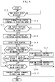
- FIG. 4 is a flowchart showing operations of a controller of the work robot system of the embodiment.
- FIG. 5 is a diagram illustrating calculation of an amount of movement in the work robot system of the embodiment.
- a work robot system 1 according to an embodiment of the present invention will be described below by using the drawings.
- the work robot system 1 of this embodiment includes: a conveying apparatus 2 that conveys an object 100 that is an object to be worked on; a robot 10 that performs predetermined task on target portions 101 of the object 100 being conveyed by the conveying apparatus 2 ; a control apparatus 20 that controls the robot 10 ; a detection apparatus 40 as a detector; and a sensor 50 mounted on the robot 10 .
- the detection apparatus 40 detects that the object 100 has been conveyed to a predetermined position.
- the detection apparatus 40 may acquire data by which positions and orientations of the target portions 101 of the object 100 being conveyed by the conveying apparatus 2 can be specified. Any device that has this function can be used as the detection apparatus 40 .
- the detection apparatus 40 is a photoelectric sensor. In this case, the detection apparatus 40 detects that the object 100 has been conveyed to a position at which the detection apparatus 40 is installed.
- the conveying apparatus 2 conveys the object 100 by driving some of a plurality of rollers 3 by means of a motor 2 a , and in this embodiment, the conveying apparatus 2 conveys the object 100 toward the right side in FIG. 1 .
- the motor 2 a may include an operating position detection device 2 b .
- the operating position detection device 2 b successively detects a rotation position and a rotation amount of an output shaft of the motor 2 a .
- the operating position detection device 2 b is an encoder. A detection value of the operating position detection device 2 b is transmitted to the control apparatus 20 .
- the target portions 101 are portions of the object 100 on which the robot 10 performs the predetermined task.
- a hand 30 of the robot 10 lifts up a part 110 and the robot 10 attaches attachment portions 111 of the part 110 onto the target portions 101 .
- shafts 111 a extending downward from the attachment portions 111 of the part 110 are fitted into holes 101 a provided in the target portions 101 of the object 100 .
- the robot 10 attaches the attachment portions 111 of the part 110 onto the target portions 101 in a state where the object 100 is being moved by the conveying apparatus 2 .
- the robot 10 is not limited to a specific type, the robot 10 of this embodiment includes a plurality of servomotors 11 that respectively drive a plurality of movable parts (see FIG. 2 ).
- Each servomotor 11 has an operating position detection device that detects an operating position of the servomotor 11 , and for example, this operating position detection device is an encoder. Detection values of the operating position detection devices are transmitted to the control apparatus 20 .
- the hand 30 is mounted at a distal end of the robot 10 .
- the hand 30 of this embodiment supports the part 110 by grasping the part 110 with a plurality of claws, but a hand that supports the part 110 by using a magnetic force, air suction, or other means can also be used.
- the hand 30 includes a servomotor 31 that drives the claws (see FIG. 2 ).
- the servomotor 31 has an operating position detection device that detects an operating position of the servomotor 31 , and for example, this operating position detection device is an encoder. A detection value of the operating position detection device is transmitted to the control apparatus 20 .
- servomotors 11 , 31 various types of servomotors, including a rotary motor and a linear motor, can be used.
- a force sensor 32 is mounted at the distal end portion of the robot 10 .
- the force sensor 32 detects forces in directions along an X-axis, a Y-axis, and a Z-axis shown in FIG. 3 and forces around the X-axis, the Y-axis, and the Z-axis.
- the force sensor 32 may be any sensor that can detect the direction and the magnitude of a force applied to the hand 30 or the part 110 grasped by the hand 30 .
- the force sensor 32 is provided between the robot 10 and the hand 30 in this embodiment, but the force sensor 32 may instead be provided inside the hand 30 .
- the sensor 50 is mounted at the distal end side of the robot 10 .
- the sensor 50 is mounted on a wrist flange of the robot 10 together with the hand 30 .
- the sensor 50 is a two-dimensional camera, a three-dimensional camera, a three-dimensional distance sensor, or the like.
- the sensor 50 of this embodiment is a two-dimensional camera, and the sensor 50 is a sensor that successively acquires image data of the target portions 101 as shown in FIG. 3 , in a state where the target portions 101 are located within a predetermined range of an angle of view.
- the sensor 50 successively transmits the image data to the control apparatus 20 .
- the image data is data by which the position of at least one of the two target portions 101 can be specified. It is also possible to specify the orientations of the target portions 101 , for example, based on the positional relationship between the two target portions 101 in the image data.
- Positions and directions of a coordinate system of the sensor 50 and positions and directions of a coordinate system of the robot 10 are associated with each other in advance in the control apparatus 20 .
- the coordinate system of the sensor 50 is set as a reference coordinate system of the robot 10 that operates based on an operation program 23 b .
- a coordinate system having the origin at a tool center point (TCP) of the hand 30 a coordinate system having the origin at a reference position of the part 110 , or the like, are represented.
- the control apparatus 20 includes: a controller 21 having a CPU, an RAM, etc.; a display device 22 ; a storage unit 23 having a non-volatile storage, an ROM, etc.; a plurality of servo controllers 24 respectively corresponding to the servomotors 11 of the robot 10 ; a servo controller 25 corresponding to the servomotor 31 of the hand 30 ; and an input unit 26 connected to the control apparatus 20 .
- the input unit 26 is an input device, such as a operation panel, that an operator can carry. In some cases, the input unit 26 wirelessly communicates with the control apparatus 20 .
- a system program 23 a is stored in the storage unit 23 , and the system program 23 a covers basic functions of the control apparatus 20 .
- the operation program 23 b is also stored in the storage unit 23 .
- a following control program 23 c and a force control program 23 d are stored in the storage unit 23 .
- the controller 21 transmits control commands for performing the predetermined task on the object 100 to the servo controllers 24 , 25 . Accordingly, the robot 10 and the hand 30 perform the predetermined task on the object 100 . Actions of the controller 21 in this process will be described with reference to the flowchart of FIG. 4 .
- step S 1 - 1 when the object 100 has been detected by the detection apparatus 40 (step S 1 - 1 ), the controller 21 starts transmitting control commands to the robot 10 and the hand 30 based on the operation program 23 b (step S 1 - 2 ). Accordingly, the object 110 is grasped by the hand 30 , and the robot 10 brings the shafts 111 a of the part 110 grasped by the hand 30 closer to the holes 101 a of the target portions 101 .
- the controller 21 may use data such as the transfer speed of the conveying apparatus 2 or the positions of the target portions 101 of the object 100 , but does not need to use such data if the amount of transfer by the conveying apparatus 2 is within the range of the field of view of the sensor 50 .
- step S 1 - 7 to be described later, the shafts 111 a of the part 110 are fitted into the holes 101 a of the object 100 based on the operation program 23 b.
- step S 1 - 2 As a result of the control of the robot 10 in step S 1 - 2 , for example, the part 110 reaches the position and orientation for fitting as shown in FIG. 1 .
- the controller 21 starts control based on the following control program 23 c (step S 1 - 4 ).
- the following two modes of control can be used as this control.
- the sensor 50 detects at least the positions of the target portions 101 , and based on the detected positions, the controller 21 causes the distal end of the robot 10 to follow the target portions 101 .
- the first one is a mode of control in which the controller 21 causes the distal end of the robot 10 to follow the target portions 101 , by constantly disposing a characteristic shape and/or a characteristic point of the object 100 at a predetermined position in the angle of view of the sensor 50 .
- the second one is a mode of control in which the controller 21 causes the distal end of the robot 10 to follow the target portions 101 , by detecting the actual position (the actual position relative to the robot 10 ) of the characteristic shape and/or the characteristic point of the object 100 , and correcting the operation program 23 b based on the difference between the position of the characteristic shape and/or the characteristic point and the actual position.
- the controller 21 detects the characteristic shape and/or the characteristic point in the image data that is successively obtained by the sensor 50 .
- the characteristic shape refers to the shape of the entire target portion 101 , the shape of the hole 101 a of the target portion 101 , the shape of a mark M ( FIG. 3 ) provided at the target portion 101 , or the like.
- the characteristic point refers to a point indicating the position of the center of gravity of the hole 101 a of the target portion 101 , a point indicating the position of the center of gravity of the mark M provided at the target portion 101 , or the like.
- the controller 21 transmits, to the servo controller 24 , control commands for constantly disposing the detected characteristic shape and/or characteristic point at the predetermined position in the image data.
- the controller 21 use a characteristic shape and/or a characteristic point that is visible to the sensor 50 while the fitting work is performed, rather than a characteristic shape and/or a characteristic point that is invisible to the sensor 50 while the fitting work is performed.
- the controller 21 can change the characteristic shape and/or the characteristic point to be used for the following control, when this characteristic shape and/or characteristic point to be used for the following control becomes invisible to the sensor 50 .
- the controller 21 In the second mode of control, using the image data successively obtained by the sensor 50 , the controller 21 detects the actual position of the characteristic shape and/or the characteristic point of the object 100 relative to a fixed coordinate system of the robot 10 . Then, the controller 21 corrects teaching points of the operation program 23 b which are taught with reference to the fixed coordinate system, based on the difference between the position of the characteristic shape and/or the characteristic point and the actual position.
- the controller 21 may further calculate the amount of movement of the target portions 101 .
- the controller 21 causes the distal end of the robot 10 to follow the target portions 101 by using also the calculated amount of movement.
- the amount of movement of the target portions 101 is successively calculated, for example, based on the image data acquired by the sensor 50 .
- the amount of movement of the target portions 101 is calculated, for example, by using the characteristic shape and/or the characteristic point appearing within the angle of view of the sensor 50 .
- the controller 21 conducts a matching process for matching characteristic points in a plurality of consecutive pieces of image data. Since the distal end of the robot 10 moves in the same direction as the object 100 in accordance with the operation program 23 b , the position of the characteristic point changes little in the plurality of consecutive pieces of image data. However, when the transfer speed of the conveying apparatus 2 and the moving speed of the distal end of the robot 10 are not exactly equal, the distal end of the robot 10 and the object 100 move relative to each other. This relative movement is captured in the plurality of consecutive pieces of image data. Moreover, the amount of movement of the target portions 101 is successively calculated by using the moving speed of the distal end of the robot 10 and the relative speed of the distal end of the robot 10 relative to the target portions 101 .
- the moving speed of the distal end of the robot 10 is a moving speed based on the control commands from the controller 21 .
- the moving speed of the distal end of the robot 10 relative to the target portions 101 is calculated based on the amount of movement of the characteristic shape and/or the characteristic point in the image data and the time taken for the movement.
- the moving speed of each of the three characteristic shapes is calculated by fitting based on the least-squares method or the like.
- an average moving speed is calculated by averaging the moving speeds of the three characteristic shapes.
- the controller 21 can cause the distal end of the robot 10 to follow the target portions 101 by using the amount of movement that has been calculated before the characteristic shape and/or the characteristic point becomes invisible.
- the controller 21 may further interpolate the detection results of the actual positions of the characteristic shape and/or the characteristic point, for example, by using a trend of the calculated amount of movement or a trend of the detection result of the actual position.
- the actual position of the characteristic shape and/or the characteristic point is calculated based on image data that is actually captured by the sensor 50 . Therefore, the acquisition cycle of the actual position is as long as the capturing cycle of the sensor 50 .
- by interpolating the detection results it is possible, for example, to detect or estimate the actual position during the acquisition cycle, or to estimate the actual position at a future moment.
- the controller 21 causes the distal end of the robot 10 to follow the target portions 101 .
- the target portions 101 are disposed at predetermined positions in the captured data acquired by the sensor 50 .
- the positions in a horizontal direction of the shafts 111 a of the attachment portions 111 of the part 110 and the positions in the horizontal direction of the holes 101 a of the target portions 101 coincide with each other.
- the coordinate system of the sensor 50 is set as the reference coordinate system of the robot 10 that is operated based on the operation program 23 b . Accordingly, the reference coordinate system of the robot 10 moves in the conveying direction of the conveying apparatus 2 , and the movement of the reference coordinate system coincides with the movement of the object 100 by the conveying apparatus 2 . In this situation, the target portions 101 of the object 100 are being moved by the conveying apparatus 2 , but when seen from the controller 21 , the target portions 101 seem stationary in the reference coordinate system.
- the controller 21 starts the force control based on the force control program 23 d (step S 1 - 5 ).
- Publicly known force control can be used as the force control.
- the robot 10 moves the part 110 in a direction away from a force detected by the force sensor 32 .
- the amount of this movement is determined by the controller 21 according to the detection value of the force sensor 32 .
- the robot 10 slightly moves the part 110 in the opposite direction from the conveying direction, away from the detected force, while following the target portions 101 in the reference coordinate system.
- step S 1 - 6 when the positions of the target portions 101 relative to the robot 10 successively detected by the sensor 50 vary beyond a predetermined reference value (step S 1 - 6 ), the controller 21 performs a first abnormality addressing action (step S 1 - 7 ).
- the variation beyond the predetermined reference value is a significant movement of the target portion 101 in the image data, a movement at a speed higher than a predetermined speed of the target portion 101 in the image data, or the like.
- the rotation speed of the motor 2 a may decrease rapidly.
- the rotation speed of the motor 2 a varies significantly in some cases. In such cases, the positions of the target portions 101 relative to the robot 10 vary beyond the predetermined reference value.
- the controller 21 performs an action of shortening the control cycle, enhancing the sensitivity of the force control, an action of stopping the progress of fitting, an action of stopping the fitting work, etc. Shortening the control cycle or enhancing the sensitivity of the force control can cause the robot 10 to move with higher responsiveness upon application of a force to the part 110 .
- the controller 21 performs an action of stopping the fitting work, an action of stopping the conveying apparatus, or an action of a combination of these actions, etc.
- step S 1 - 8 When the detection value of the force sensor 32 exceeds a predetermined reference value (step S 1 - 8 ), the controller 21 performs a second abnormality addressing action (step S 1 - 9 ).
- the controller 21 performs an action of stopping the robot 10 , an action of moving the robot 10 at a low speed in a direction away from the direction of the force detected by the force sensor 32 , an action of stopping the conveying apparatus, or an action of a combination of these actions, etc.
- the controller 21 performs an action of stopping the robot 10 .
- the controller 21 determines whether the fitting work has been completed (step S 1 - 10 ), and when the fitting work has been completed, sends control commands to the robot 10 and the hand 30 (step S 1 - 11 ). Accordingly, the hand 30 moves away from the part 110 , and the hand 30 is moved by the robot 10 to a stand-by position or a place where a next part 110 is stocked.
- the controller 21 may be able to recognize the positional relationship between the object 100 and the part 110 supported by the robot 10 , and to recognize whether the two are in contact with each other.
- the controller 21 can recognize, in the absence of force control, an abnormality of the conveying apparatus 2 in which the amount the object 100 is moved by the conveying apparatus 2 varies significantly.
- the controller 21 performs the force control by using the detection value of the force sensor 32 , while causing the part 110 supported by the robot 10 to follow the target portions 101 by using the detection result of the sensor 50 .
- the controller 21 causes the part 110 of the robot 10 to follow the target portions 101 by using the detection result of the sensor 50 .
- the controller 21 can accurately control the position and the orientation of the part 110 supported by the robot 10 , relative to the target portions 101 of the object 100 being conveyed by the conveying apparatus 2 . This is advantageous in realizing prevention of damage to the robot 10 , the conveying apparatus 2 , the object 100 , etc. without shortening the control cycle, or enhancing the sensitivity, of the force control, and also in suppressing oscillation of the robot 10 .
- the detection apparatus 40 that detects at least the positions of the target portions 101 of the object 100 on the conveying apparatus 2 is provided, and the controller 21 brings the part 110 supported by the robot 10 closer to the target portions 101 based on the detection result of the detection apparatus 40 .
- the work efficiency is improved by the robot 10 thus operating based on the detection result of the detection apparatus 40 .
- the controller 21 may also use the detection result of the operating position detection device 2 b to bring the part 110 supported by the robot 10 closer to the target portions 101 .
- the detection result of the operating position detection device 2 b is also used, the accuracy of the control of bringing the part 110 closer to the target portions 101 is enhanced.
- the detection apparatus 40 is a photoelectric sensor in this embodiment, the detection apparatus 40 may instead be, for example, a two-dimensional camera, a three-dimensional camera, or a three-dimensional distance sensor that is disposed above, on a side of, or below the conveying apparatus 2 , or a sensor that measures the shape of an object by emitting linear light to the object.
- the controller 21 may be able to recognize the positions and the orientations of the target portions 101 of the object 100 being conveyed by the conveying apparatus 2 , based on image data that is a detection result of the detection apparatus 40 .
- the controller 21 can more accurately bring the shafts 111 a of the part 110 closer to the holes 101 a of the target portions 101 in step S 1 - 2 .
- a processing tool may be supported at the distal end of the robot 10 , and the robot 10 may perform processing as the predetermined task on the object 100 being conveyed by the conveying apparatus 2 .
- the processing tool refers to a drill, a milling cutter, a drill tap, a deburring tool, or other tools.
- effects similar to those described above can be achieved as, for example, the processing tool is brought closer to the target portions 101 in step S 1 - 2 and the force control is performed according to contact between the processing tool and the target portions 101 in step S 1 - 7 .
- step S 1 - 4 the controller 21 can also use the positions of the target portions 101 in the image data, the moving speed and direction of the target portions 101 in the image data, etc. to cause the distal end of the robot 10 to follow the target portions 101 .
- Other publicly known methods can also be used to cause the distal end of the robot 10 to follow the target portions 101 . Effects similar to those described above can be achieved also when such a configuration is used.
- the controller 21 also can cause the distal end of the robot 10 to follow the target portions 101 by using the detection result of the sensor 50 .
- the controller 21 can perform the first abnormality addressing action in step S 1 - 7 .
- the amount of movement is calculated based on the image data that is captured by the sensor 50 in reality. Therefore, if the acquisition cycle of the amount of movement is matched with the capturing cycle of the sensor 50 , the acquisition cycle of the amount of movement will become as long as the capturing cycle of the sensor 50 .
- the controller 21 specifies a variation trend of the amount of movement by using a calculation result of a plurality of consecutive amounts of movement. Then, the controller 21 can set an interpolating amount of movement between one amount of movement and another along the specified trend.
- step S 1 - 9 the controller 21 may perform, as the second abnormality addressing action, an action such as stopping the motor 2 a of the conveying apparatus 2 or decelerating the motor 2 a of the conveying apparatus 2 .
- the force sensor 32 is mounted at the distal end of the robot 10 .
- it is also possible to dispose the force sensor 32 for example, between the conveying apparatus 2 and the object 100 or inside the object 100 .
- the force control based on the detection value of the force sensor 32 can be performed, and effects similar to those described above can be thereby achieved.
- the sensor 50 may be mounted at a part of the robot 10 other than the wrist flange. Also in this case, the controller 21 can recognize the positional relationship between the part 110 supported by the robot 10 and the object 100 being conveyed by the conveying apparatus 2 based on the detection result of the sensor 50 . Thus, effects similar to those described above can be achieved.
- a work robot system of an aspect of the present invention includes: a conveying apparatus that conveys an object; a robot that performs a predetermined task on a target portion of the object being conveyed by the conveying apparatus; a controller that controls the robot; a sensor that is attached to the robot and detects a position, relative to the robot, of the target portion of the object being conveyed by the conveying apparatus; and a force detector that detects a force generated by contact between the object and a part or a tool supported by the robot, wherein when the robot is performing the predetermined task, the controller performs force control based on a detection value of the force detector while controlling the robot by using a detection result of the sensor.
- the controller may be able to recognize the positional relationship between the object and the part or the tool supported by the robot, and to recognize whether the two are in contact with each other.
- the controller can recognize, in the absence of force control, an abnormality of the conveying apparatus in which the moving amount the object moved by the conveying apparatus varies significantly. It is therefore possible to realize prevention of damage to the robot, the conveying apparatus, the object, etc. without unreasonably shortening the control cycle of force control, and also to suppress oscillation of the robot.
- the controller may perform the force control by using the detection value of the force detector, while causing the part or the tool supported by the robot to follow the target portion by using the detection result of the sensor.
- the controller causes the part or the tool of the robot to follow the target portion by using the detection result of the sensor.
- the controller can accurately control the position and the orientation of the part or the tool supported by the robot, relative to the target portion of the object being conveyed by the conveying apparatus. This is advantageous in realizing prevention of damage to the robot, the conveying apparatus, the object, etc. without shortening the control cycle, or enhancing the sensitivity, of the force control, and also in suppressing oscillation of the robot.
- the work robot system may further include a detector that detects at least a position of the target portion of the object on the conveying apparatus, and the controller may bring the part or the tool of the robot closer to the target portion based on a detection result of the detector.
- This aspect is advantageous in accurately performing the control of bringing the part or the tool supported by the robot closer to the target portion.
- At least one of the controller and the conveying apparatus may perform an abnormality addressing action when the position of the target portion relative to the robot detected by the sensor varies beyond a predetermined reference value.
- the controller in the state where the positional relationship between the object and the part or the tool supported by the robot is recognized as described above, the controller further performs the abnormality addressing action based on the detection result of the sensor.
- This configuration is advantageous in reliably realizing prevention of damage to the robot, the conveying apparatus, the object, etc., and also in suppressing oscillation of the robot.
- the above aspects can efficiently realize prevention of damage to the robot, the conveying apparatus, the object, etc.
Abstract
Description
- 1 Work robot system
- 2 Conveying apparatus
- 2 a Motor
- 2 b Operating position detection device
- 3 Roller
- 10 Robot
- 11 Servomotor
- 20 Control apparatus
- 21 Controller
- 22 Display device
- 23 Storage unit
- 23 a System program
- 23 b Operation program
- 23 c Following control program
- 23 d Force control program
- 24 Servo controller
- 25 Servo controller
- 26 Input unit
- 30 Hand
- 31 Servomotor
- 32 Force sensor
- 40 Detection apparatus
- 50 Sensor
- 100 Object
- 101 Target portion
- 101 a Hole
- 110 Part
- 111 Attachment portion
- 111 a Shaft
Claims (5)
Priority Applications (1)
| Application Number | Priority Date | Filing Date | Title |
|---|---|---|---|
| US17/847,651 US11904483B2 (en) | 2018-02-08 | 2022-06-23 | Work robot system |
Applications Claiming Priority (3)
| Application Number | Priority Date | Filing Date | Title |
|---|---|---|---|
| JP2018021181A JP6748126B2 (en) | 2018-02-08 | 2018-02-08 | Work robot system |
| JPJP2018-021181 | 2018-02-08 | ||
| JP2018-021181 | 2018-02-08 |
Related Child Applications (1)
| Application Number | Title | Priority Date | Filing Date |
|---|---|---|---|
| US17/847,651 Continuation US11904483B2 (en) | 2018-02-08 | 2022-06-23 | Work robot system |
Publications (2)
| Publication Number | Publication Date |
|---|---|
| US20190240841A1 US20190240841A1 (en) | 2019-08-08 |
| US11407115B2 true US11407115B2 (en) | 2022-08-09 |
Family
ID=67308505
Family Applications (2)
| Application Number | Title | Priority Date | Filing Date |
|---|---|---|---|
| US16/245,593 Active 2039-10-30 US11407115B2 (en) | 2018-02-08 | 2019-01-11 | Work robot system |
| US17/847,651 Active US11904483B2 (en) | 2018-02-08 | 2022-06-23 | Work robot system |
Family Applications After (1)
| Application Number | Title | Priority Date | Filing Date |
|---|---|---|---|
| US17/847,651 Active US11904483B2 (en) | 2018-02-08 | 2022-06-23 | Work robot system |
Country Status (4)
| Country | Link |
|---|---|
| US (2) | US11407115B2 (en) |
| JP (1) | JP6748126B2 (en) |
| CN (2) | CN110125906B (en) |
| DE (1) | DE102019102859B4 (en) |
Families Citing this family (8)
| Publication number | Priority date | Publication date | Assignee | Title |
|---|---|---|---|---|
| JP6849631B2 (en) | 2018-04-23 | 2021-03-24 | ファナック株式会社 | Work robot system and work robot |
| US10369701B1 (en) * | 2018-10-30 | 2019-08-06 | Mujin, Inc. | Automated package registration systems, devices, and methods |
| JP7306937B2 (en) * | 2019-09-25 | 2023-07-11 | ファナック株式会社 | A control device for a robot device that adjusts the position of a member supported by a robot |
| DE112021000503T5 (en) * | 2020-01-10 | 2022-11-17 | Fanuc Corporation | control system |
| US20230138649A1 (en) * | 2020-05-19 | 2023-05-04 | Fanuc Corporation | Following robot |
| JP7314871B2 (en) * | 2020-07-09 | 2023-07-26 | 新東工業株式会社 | Strength measuring device and strength measuring method |
| JP7434196B2 (en) | 2021-01-29 | 2024-02-20 | 日立グローバルライフソリューションズ株式会社 | work system |
| DE102021106990A1 (en) | 2021-03-22 | 2022-09-22 | Ferrobotics Compliant Robot Technology Gmbh | Force-controlled handling device for robot-assisted surface treatment |
Citations (15)
| Publication number | Priority date | Publication date | Assignee | Title |
|---|---|---|---|---|
| JPS61243514A (en) | 1985-04-22 | 1986-10-29 | Nissan Motor Co Ltd | Robot controller |
| JPH0872764A (en) | 1994-09-01 | 1996-03-19 | Mazda Motor Corp | Production line controller |
| JPH08286701A (en) | 1995-04-11 | 1996-11-01 | Nissan Motor Co Ltd | Multi-robot control method and system |
| JPH0972717A (en) | 1995-09-04 | 1997-03-18 | Fanuc Ltd | Acquiring and processing method for image |
| JP2002018754A (en) | 2000-07-10 | 2002-01-22 | Toyota Central Res & Dev Lab Inc | Robot device and its control method |
| US20030051326A1 (en) | 1999-06-25 | 2003-03-20 | Lawrence Lawson | Robotic apparatus and method for mounting a valve stem on a wheel rim |
| US6681151B1 (en) * | 2000-12-15 | 2004-01-20 | Cognex Technology And Investment Corporation | System and method for servoing robots based upon workpieces with fiducial marks using machine vision |
| US20060111810A1 (en) * | 2002-02-16 | 2006-05-25 | Mun-Sang Kim | Working robot, actuator and control method thereof |
| US20100017033A1 (en) * | 2008-07-18 | 2010-01-21 | Remus Boca | Robotic systems with user operable robot control terminals |
| US20110087360A1 (en) * | 2008-03-31 | 2011-04-14 | Abb Research Ltd. | Robot parts assembly on a workpiece moving on an assembly line |
| JP2011073128A (en) | 2009-09-30 | 2011-04-14 | Almedio Inc | Robot system |
| JP2011110620A (en) | 2009-11-24 | 2011-06-09 | Toyota Industries Corp | Method of controlling action of robot, and robot system |
| US20110208347A1 (en) | 2010-02-22 | 2011-08-25 | Honda Motor Co., Ltd. | Machining system and method |
| WO2017014303A1 (en) | 2015-07-23 | 2017-01-26 | オリンパス株式会社 | Medical system and operation method therefor |
| US20180370023A1 (en) | 2017-06-26 | 2018-12-27 | Fanuc Corporation | Robot system |
Family Cites Families (9)
| Publication number | Priority date | Publication date | Assignee | Title |
|---|---|---|---|---|
| US3576540A (en) * | 1967-11-20 | 1971-04-27 | Sundstrand Corp | Plural machine tool and part handling control system |
| AU3350400A (en) * | 1999-01-29 | 2000-08-18 | Georgia Tech Research Corporation | Uncalibrated dynamic mechanical system controller |
| JP2005111607A (en) * | 2003-10-07 | 2005-04-28 | Fanuc Ltd | Material flow tracking device using robot |
| JP4864363B2 (en) * | 2005-07-07 | 2012-02-01 | 東芝機械株式会社 | Handling device, working device, and program |
| JP5464176B2 (en) * | 2011-06-20 | 2014-04-09 | 株式会社安川電機 | Picking system |
| CN106272416B (en) * | 2016-08-29 | 2020-12-29 | 上海交通大学 | Robot slender shaft precision assembly system and method based on force sense and vision |
| CN106272424B (en) * | 2016-09-07 | 2017-10-27 | 华中科技大学 | A kind of industrial robot grasping means based on monocular camera and three-dimensional force sensor |
| JP7314475B2 (en) * | 2016-11-11 | 2023-07-26 | セイコーエプソン株式会社 | ROBOT CONTROL DEVICE AND ROBOT CONTROL METHOD |
| CN106737697A (en) * | 2017-03-13 | 2017-05-31 | 安徽朗巴智能科技有限公司 | A kind of automatic setup system based on the people that puts together machines |
-
2018
- 2018-02-08 JP JP2018021181A patent/JP6748126B2/en active Active
-
2019
- 2019-01-11 US US16/245,593 patent/US11407115B2/en active Active
- 2019-02-02 CN CN201910106489.3A patent/CN110125906B/en active Active
- 2019-02-02 CN CN202310844799.1A patent/CN116619341A/en active Pending
- 2019-02-05 DE DE102019102859.0A patent/DE102019102859B4/en active Active
-
2022
- 2022-06-23 US US17/847,651 patent/US11904483B2/en active Active
Patent Citations (22)
| Publication number | Priority date | Publication date | Assignee | Title |
|---|---|---|---|---|
| JPS61243514A (en) | 1985-04-22 | 1986-10-29 | Nissan Motor Co Ltd | Robot controller |
| JPH0872764A (en) | 1994-09-01 | 1996-03-19 | Mazda Motor Corp | Production line controller |
| JPH08286701A (en) | 1995-04-11 | 1996-11-01 | Nissan Motor Co Ltd | Multi-robot control method and system |
| JPH0972717A (en) | 1995-09-04 | 1997-03-18 | Fanuc Ltd | Acquiring and processing method for image |
| US20030051326A1 (en) | 1999-06-25 | 2003-03-20 | Lawrence Lawson | Robotic apparatus and method for mounting a valve stem on a wheel rim |
| US20050177989A1 (en) * | 1999-06-25 | 2005-08-18 | Burke E. Porter Machinery Company, A Corporation Of The State Of Michigan | Robotic apparatus and method for mounting a valve stem on a wheel rim |
| US20070107183A1 (en) | 1999-06-25 | 2007-05-17 | Burke E. Porter Machinery Company, A Corporation Of The State Of Michigan | Robotic apparatus and method for mounting a valve stem on a wheel rim |
| JP2002018754A (en) | 2000-07-10 | 2002-01-22 | Toyota Central Res & Dev Lab Inc | Robot device and its control method |
| US6681151B1 (en) * | 2000-12-15 | 2004-01-20 | Cognex Technology And Investment Corporation | System and method for servoing robots based upon workpieces with fiducial marks using machine vision |
| US20060111810A1 (en) * | 2002-02-16 | 2006-05-25 | Mun-Sang Kim | Working robot, actuator and control method thereof |
| EP1405690B1 (en) | 2002-10-04 | 2017-04-19 | Burke E. Porter Machinery Company | Robotic apparatus and method for mounting a valve stem on a wheel rim |
| US20110087360A1 (en) * | 2008-03-31 | 2011-04-14 | Abb Research Ltd. | Robot parts assembly on a workpiece moving on an assembly line |
| US20100017033A1 (en) * | 2008-07-18 | 2010-01-21 | Remus Boca | Robotic systems with user operable robot control terminals |
| JP2011073128A (en) | 2009-09-30 | 2011-04-14 | Almedio Inc | Robot system |
| JP2011110620A (en) | 2009-11-24 | 2011-06-09 | Toyota Industries Corp | Method of controlling action of robot, and robot system |
| US20110208347A1 (en) | 2010-02-22 | 2011-08-25 | Honda Motor Co., Ltd. | Machining system and method |
| JP2011167831A (en) | 2010-02-22 | 2011-09-01 | Honda Motor Co Ltd | System and method of machining |
| WO2017014303A1 (en) | 2015-07-23 | 2017-01-26 | オリンパス株式会社 | Medical system and operation method therefor |
| EP3326566A1 (en) | 2015-07-23 | 2018-05-30 | Olympus Corporation | Medical system and operation method therefor |
| US20180193102A1 (en) | 2015-07-23 | 2018-07-12 | Olympus Corporation | Medical system and operation method therefor |
| US20180370023A1 (en) | 2017-06-26 | 2018-12-27 | Fanuc Corporation | Robot system |
| JP2019005856A (en) | 2017-06-26 | 2019-01-17 | ファナック株式会社 | Robot system |
Non-Patent Citations (5)
| Title |
|---|
| Japanese Office Action dated Apr. 21, 2020, in connection with corresponding JP Application No. 2018-021181 (7 pgs., including machine-generated English translation). |
| Japanese Office Action dated Jan. 21, 2020, in connection with corresponding JP Application No. 2018-021181 (7 pgs., including machine-generated English translation). |
| Japanese Search Report dated Jan. 14, 2020, in connection with corresponding JP Application No. 2018-021181 (22 pgs., including machine-generated English translation). |
| Office Action dated Oct. 19, 2021, in connection with corresponding German Application No. 102019102859.0 (10 pp., including machine-generated English translation). |
| U.S. Appl. No. 16/245,573, Masafumi Ooba, filed Jan. 11, 2019. |
Also Published As
| Publication number | Publication date |
|---|---|
| US20220324118A1 (en) | 2022-10-13 |
| CN116619341A (en) | 2023-08-22 |
| DE102019102859B4 (en) | 2022-05-12 |
| JP2019136808A (en) | 2019-08-22 |
| CN110125906B (en) | 2023-07-11 |
| JP6748126B2 (en) | 2020-08-26 |
| DE102019102859A1 (en) | 2019-08-08 |
| CN110125906A (en) | 2019-08-16 |
| US20190240841A1 (en) | 2019-08-08 |
| US11904483B2 (en) | 2024-02-20 |
Similar Documents
| Publication | Publication Date | Title |
|---|---|---|
| US11904483B2 (en) | Work robot system | |
| CN109922931B (en) | Robot control device, robot system, and robot control method | |
| US10780579B2 (en) | Work robot system | |
| CN111470309B (en) | Following robot and working robot system | |
| US10357876B2 (en) | Robot system | |
| WO2016103303A1 (en) | Self-propelled articulated robot | |
| CN109746911B (en) | Machining system | |
| US10603798B2 (en) | Robot | |
| US11161697B2 (en) | Work robot system and work robot | |
| US20180257230A1 (en) | Positioning device and positioning method of processing tool | |
| US11161239B2 (en) | Work robot system and work robot | |
| CN108732998B (en) | Control system for machine tool | |
| US20230364812A1 (en) | Robot system | |
| WO2018088199A1 (en) | Robot control device, robot, robotic system, and robotic control method | |
| CN115666879A (en) | Control device, robot system, and control method for causing robot to perform work on workpiece | |
| WO2021235331A1 (en) | Following robot | |
| WO2023166588A1 (en) | Work robot system |
Legal Events
| Date | Code | Title | Description |
|---|---|---|---|
| AS | Assignment |
Owner name: FANUC CORPORATION, JAPAN Free format text: ASSIGNMENT OF ASSIGNORS INTEREST;ASSIGNOR:OOBA, MASAFUMI;REEL/FRAME:047966/0827 Effective date: 20181114 |
|
| FEPP | Fee payment procedure |
Free format text: ENTITY STATUS SET TO UNDISCOUNTED (ORIGINAL EVENT CODE: BIG.); ENTITY STATUS OF PATENT OWNER: LARGE ENTITY |
|
| STPP | Information on status: patent application and granting procedure in general |
Free format text: DOCKETED NEW CASE - READY FOR EXAMINATION |
|
| STPP | Information on status: patent application and granting procedure in general |
Free format text: NON FINAL ACTION MAILED |
|
| STPP | Information on status: patent application and granting procedure in general |
Free format text: RESPONSE TO NON-FINAL OFFICE ACTION ENTERED AND FORWARDED TO EXAMINER |
|
| STPP | Information on status: patent application and granting procedure in general |
Free format text: FINAL REJECTION MAILED |
|
| STPP | Information on status: patent application and granting procedure in general |
Free format text: RESPONSE AFTER FINAL ACTION FORWARDED TO EXAMINER |
|
| STPP | Information on status: patent application and granting procedure in general |
Free format text: ADVISORY ACTION MAILED |
|
| STPP | Information on status: patent application and granting procedure in general |
Free format text: DOCKETED NEW CASE - READY FOR EXAMINATION |
|
| STPP | Information on status: patent application and granting procedure in general |
Free format text: NON FINAL ACTION MAILED |
|
| STPP | Information on status: patent application and granting procedure in general |
Free format text: RESPONSE TO NON-FINAL OFFICE ACTION ENTERED AND FORWARDED TO EXAMINER |
|
| STPP | Information on status: patent application and granting procedure in general |
Free format text: FINAL REJECTION MAILED |
|
| STPP | Information on status: patent application and granting procedure in general |
Free format text: RESPONSE AFTER FINAL ACTION FORWARDED TO EXAMINER |
|
| STPP | Information on status: patent application and granting procedure in general |
Free format text: NOTICE OF ALLOWANCE MAILED -- APPLICATION RECEIVED IN OFFICE OF PUBLICATIONS |
|
| STCF | Information on status: patent grant |
Free format text: PATENTED CASE |