US11406848B2 - Ultrasonic therapy device using HIFU and control method thereof - Google Patents
Ultrasonic therapy device using HIFU and control method thereof Download PDFInfo
- Publication number
- US11406848B2 US11406848B2 US16/313,654 US201616313654A US11406848B2 US 11406848 B2 US11406848 B2 US 11406848B2 US 201616313654 A US201616313654 A US 201616313654A US 11406848 B2 US11406848 B2 US 11406848B2
- Authority
- US
- United States
- Prior art keywords
- conversion elements
- hifu
- active
- ultrasound
- converter
- Prior art date
- Legal status (The legal status is an assumption and is not a legal conclusion. Google has not performed a legal analysis and makes no representation as to the accuracy of the status listed.)
- Active, expires
Links
Images


Classifications
-
- A—HUMAN NECESSITIES
- A61—MEDICAL OR VETERINARY SCIENCE; HYGIENE
- A61N—ELECTROTHERAPY; MAGNETOTHERAPY; RADIATION THERAPY; ULTRASOUND THERAPY
- A61N7/00—Ultrasound therapy
-
- A—HUMAN NECESSITIES
- A61—MEDICAL OR VETERINARY SCIENCE; HYGIENE
- A61N—ELECTROTHERAPY; MAGNETOTHERAPY; RADIATION THERAPY; ULTRASOUND THERAPY
- A61N7/00—Ultrasound therapy
- A61N7/02—Localised ultrasound hyperthermia
-
- A—HUMAN NECESSITIES
- A61—MEDICAL OR VETERINARY SCIENCE; HYGIENE
- A61N—ELECTROTHERAPY; MAGNETOTHERAPY; RADIATION THERAPY; ULTRASOUND THERAPY
- A61N7/00—Ultrasound therapy
- A61N2007/0078—Ultrasound therapy with multiple treatment transducers
-
- A—HUMAN NECESSITIES
- A61—MEDICAL OR VETERINARY SCIENCE; HYGIENE
- A61N—ELECTROTHERAPY; MAGNETOTHERAPY; RADIATION THERAPY; ULTRASOUND THERAPY
- A61N7/00—Ultrasound therapy
- A61N2007/0086—Beam steering
- A61N2007/0095—Beam steering by modifying an excitation signal
Definitions
- the present disclosure relates to ultrasound technology for noninvasive treatment, and more particularly, to an ultrasound therapy device for controlling an ultrasonic converter assembly for performing treatment using high intensity focused ultrasound (HIFU) and a method for controlling a plurality of ultrasonic converters provided in the ultrasound therapy device.
- HIFU high intensity focused ultrasound
- HIFU high intensity focused ultrasound
- an ultrasound tumor treatment device employs sphere focusing. Ultrasound emitted from all points is focused on the center of a sphere.
- the emitter on the ultrasound treatment device emits ultrasound from the outside of the body to the inside of the body, and the ultrasound is focused to form a high energy focal point during emission and transmission. Accordingly, high intensity and continuous ultrasound energy is applied to the patient's lesion region.
- the effect of too high temperature (65-100° C.), the cavitation effect, the mechanical effect and the sonochemical effect generated from the focal point are used to selectively cause coagulative necrosis of the affected tissue, and prevent the proliferation, invasion and metastasis of tumor.
- the accurate, safe and effective localization of the focal point is essential for successful treatment while applying HIFU treatment, and there is a need to further improve the convenience of operation for positioning the target. Accordingly, in performing treatment through HIFU signals without damaging the important vessels and organs, most of all, it is required to identify an area under influence of HIFU signals and accurately know the influence on an area to be treated and other normal tissues.
- the related literature presented below introduces the structure of a converter (transducer) that can reduce the size of the grating lobe in implementing high intensity focused ultrasound.
- the technical problem to be solved by the embodiments of the present disclosure is, when necrotizing the lesion through high intensity focused ultrasound treatment, to minimize the generation of the grating lobe by beam focusing on an area that is not intended by an operator, and solve the problem with ultrasound therapy efficiency reduction caused by ultrasonic irradiation damage accumulated in normal tissues while long-term treatment continues.
- HIFU high intensity focused ultrasound
- the control unit changes a combination of conversion elements that constitute active conversion elements over time, and performs control such that beam focusing through the conversion elements included in the combination before the change and beam focusing through the conversion elements included in the combination after the change have a same location of main lobe and different locations of grating lobe.
- the ultrasound therapy device may further include a storage unit which generates and pre-stores a plurality of combinations of conversion elements having a same location of main lobe and different locations of grating lobe, and the control unit may read the combinations of conversion elements stored in the storage unit in a sequential order, and make replacement and drive as active conversion elements at a predetermined time interval.
- control unit may change a combination of conversion elements that constitute active conversion elements for varying distances between conversion elements from a center of the array type HIFU converter over time.
- the active conversion elements may be selected from conversion elements arranged randomly on the array type HIFU converter, or arranged forming a sparse array, a Fermat's spiral or a concentric ring, or arranged symmetrically with respect to one reference axis.
- an ultrasound therapy method adopting an electrical control scheme includes (a) selecting and driving some conversion elements from an array type HIFU converter having a plurality of HIFU conversion elements, (b) treating tissues in a focusing area by irradiating ultrasound signals to an object through the driven active conversion elements to generate heat energy, (c) after an elapse of a predetermined time period, selecting conversion elements for a different combination of conversion elements and driving as new active conversion elements in replacement of the active conversion elements, and (d) treating the tissues in the focusing area using the driven new active conversion elements.
- the step (c) includes selecting new active conversion elements by changing a combination of conversion elements that constitute active conversion elements, and stopping the operation of the existing active conversion elements, and driving the new active conversion elements, and performing control such that beam focusing through the conversion elements included in the combination before the change and beam focusing through the conversion elements included in the combination after the change have a same location of main lobe and different locations of grating lobe.
- the ultrasound therapy method may further include generating and pre-storing a plurality of combinations of conversion elements having a same location of main lobe and different locations of grating lobe, and the step (c) may include reading the pre-stored combinations of conversion elements in a sequential order and making replacement and driving as active conversion elements at a predetermined time interval.
- the step (c) may include changing a combination of conversion elements that constitute active conversion elements for varying distances between conversion elements from a center of the array type HIFU converter over time.
- the active conversion elements selected through the step (a) and the step (c) may be selected from conversion elements arranged randomly on the array type HIFU converter, or arranged forming a sparse array, a Fermat's spiral or a concentric ring, or arranged symmetrically with respect to one reference axis.
- an ultrasound therapy device adopting a mechanical control scheme includes an array type HIFU converter having a plurality of HIFU conversion elements, a control unit which performs control to treat tissues in a focusing area by driving the conversion elements of the array type HIFU converter and irradiating ultrasound signals to an object to generate heat energy, and a rotation unit which rotates the array type HIFU converter while maintaining a plane facing the object.
- the rotation unit may rotate the array type HIFU converter around a center of the array type HIFU converter to continuously change a location of grating lobe over time.
- the control unit may fix a location of main lobe to the object to be treated without change in beam focusing signal irrespective of rotation of the array type HIFU converter.
- the control unit may control the beam focusing signals of each of the conversion elements of the array type HIFU converter such that a main lobe changing in focusing position with the rotation of the array type HIFU converter is disposed in the object to be treated.
- the conversion elements may be arranged randomly on the array type HIFU converter, or arranged forming a sparse array, a Fermat's spiral or a concentric ring, or arranged symmetrically with respect to one reference axis.
- control unit may drive all or some of the conversion elements of the array type HIFU converter, and perform control such that when some conversion elements are driven, the focusing area formed by beam focusing implemented by the driven conversion elements is disposed on the rotation axis of the rotation unit.
- an ultrasound therapy method adopting a mechanical control scheme includes (a) treating tissues in a focusing area by driving conversion elements of an array type HIFU converter having a plurality of high intensity focused ultrasound (HIFU) conversion elements and irradiating ultrasound signals to an object to generate heat energy, and (b) rotating the array type HIFU converter while maintaining a plane facing the object to continuously change a location of grating lobe over time.
- HIFU high intensity focused ultrasound
- the step (b) may include fixing a location of main lobe to the object to be treated without change in beam focusing signal irrespective of rotation of the array type HIFU converter.
- the step (b) may include controlling the beam focusing signals of each of the conversion elements of the array type HIFU converter such that a main lobe changing in focusing position with the rotation of the array type HIFU converter is disposed in the object to be treated.
- the step (b) may include performing control such that the focusing area formed by beam focusing implemented by the driven conversion elements is disposed on a rotation axis of the rotation unit.
- the embodiments of the present disclosure continuously changes the location of the grating lobe while fixing the location of the main lobe, thereby suppressing the side effects of ultrasound focused on an unintended area by the grating lobe and damage of normal tissues, mitigating pain in patients during treatment, reducing the risk for burns to skin in contact with the converter as well as the cooling time of the converter, and enabling efficient ultrasound therapy.
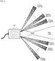
- FIG. 1 is a diagram showing a high intensity focused ultrasound (HIFU) converter structure implemented with a sparse array structure.
- HIFU high intensity focused ultrasound
- FIG. 2 is an exemplary diagram showing a beam pattern generated by an HIFU converter adopting an array structure such as a sparse array scheme.
- FIG. 3 is a block diagram showing an ultrasound therapy device adopting an electrical control scheme that changes the location of the grating lobe according to an embodiment of the present disclosure.
- FIG. 4 is an exemplary diagram showing a beam pattern generated through the ultrasound therapy device of FIG. 3 according to an embodiment of the present disclosure.
- FIG. 5 is a flowchart showing an ultrasound therapy method adopting an electrical control scheme that changes the location of the grating lobe according to an embodiment of the present disclosure.
- FIG. 6 is an exemplary diagram showing the time-sequential operation of active conversion elements through an electrical control scheme according to an embodiment of the present disclosure.
- FIG. 7 is an exemplary graph showing a beam pattern generated through an electrical control scheme according to an embodiment of the present disclosure.
- FIG. 8 is a block diagram showing an ultrasound therapy device adopting a mechanical control scheme that changes the location of the grating lobe according to another embodiment of the present disclosure.
- FIG. 9 is an exemplary diagram showing changes in the location of conversion elements over time through a mechanical control scheme according to another embodiment of the present disclosure.
- FIGS. 10 and 11 are flowcharts showing an ultrasound therapy method adopting a mechanical control scheme that changes the location of the grating lobe according to another embodiment of the present disclosure.
- An ultrasound therapy device includes: an array type high intensity focused ultrasound (HIFU) converter having a plurality of HIFU conversion elements; and a control unit to perform control to treat tissues in a focusing area by selecting and driving some of the conversion elements of the array type HIFU converter and irradiating ultrasound signals to an object through the driven active conversion elements to generate heat energy, wherein, after an elapse of a predetermined time period, the control unit drives conversion elements selected for a different combination of conversion elements as new active conversion elements in replacement of the active conversion elements.
- HIFU high intensity focused ultrasound
- High intensity focused ultrasound is noninvasive treatment technology that irradiates high intensity of ultrasound into human body tissues to necrotize lesion tissues such as cancers in the human body tissue, and after converting electrical signals to ultrasound signals using a plurality of converters arranged in a probe, irradiates the ultrasound signals into the human body.
- HIFU focuses higher intensity of ultrasound signals than those used for ultrasound imaging on an area to be treated and irradiates a few times to necrotize the lesion tissues.
- the irradiated energy is converted to heat energy and heats the tissues disposed in the focusing area of ultrasound to high temperature into coagulative necrosis.
- the HIFU converter used in treatment is made by attaching a few tens or hundreds of ultrasonic conversion elements in the shape of a circular or polygonal plate to a concave frame with the radius that is equal to the focal length.
- This converter is a so-called array type converter, and the array type converter may bring about a spot on which unintended ultrasonic energy is focused in an area other than the focal point according to the location and shape of the conversion elements.
- Emission in an unintended area is known as grating lobe, which may cause local heating in an unintended area during HIFU treatment.
- the heating by the grating lobe is one of side effects frequently occurring during HIFU treatment, and causes a serious problem such as pain or necrosis of normal tissues.
- the wider the steering angle the greater the influence of the grating lobe.
- the electrical steering range of ultrasound is limited to avoid the influence of the grating lobe, and after all, the physical movements of the converter are needed, and there are problems with longer treatment time and lower treatment efficiency.
- a cooling process is performed during treatment, which also causes the problems with longer treatment time and lower treatment efficiency.
- FIG. 1 is a diagram showing an HIFU converter structure implemented with a sparse array structure, and these methods can reduce the size of the grating lobe, but rather they are confronted by a side effect that the grating lobe is generated over a wider area.
- FIG. 2 is an exemplary diagram showing a beam pattern generated by an HIFU converter adopting an array structure such as a sparse array scheme, and referring to FIG. 2 , it shows the location of grating lobe formed in an unintended area other than the main lobe where substantial treatment is performed with respect to a focal point of a beam formed from the HIFU converter 10 .
- the embodiments of the present disclosure presented below adopt a control scheme that maintains focusing of ultrasound on a focusing area, and can minimize the grating lobe resulting from beam focusing in an unintended area, to minimize damage of normal tissues and increase the treatment efficiency.
- the embodiments of the present disclosure controls the ultrasonic irradiation method to fix the location of the main lobe to the focusing area, and continuously change the location of the grating lobe during treatment, so as to reduce the size of the grating lobe that is accumulated while treatment continues.
- the substantial control method may be largely classified into an electrical control scheme and a mechanical control scheme.
- FIG. 3 is a block diagram showing the ultrasound therapy device adopting the electrical control scheme that changes the location of the grating lobe according to an embodiment of the present disclosure.
- the array type HIFU converter 10 has a plurality of HIFU conversion elements, and has a structure in which a larger number of conversion elements than active ultrasonic conversion elements (active elements) operating at one point is arranged on a frame regularly or irregularly. That is, instead of simultaneously driving all the conversion elements of the array type HIFU converter 10 , some of them are driven and used for beam focusing.
- FIG. 3 it exemplarily shows that active conversion elements 13 of a first group selected three conversion elements, and active conversion elements 15 of a second group selected a combination of three other conversion elements.
- the first group and the second group are driven at different points in time, and a combination of conversion elements included in each group are only different and each of all the individual conversion elements does not need to be arranged in a non-overlapping manner.
- one conversion element (indicated by slashed lines) in the first group 13 and the second group 15 is included in common.
- the active conversion elements driven at one point in time may be may be selected from conversion elements arranged randomly on the array type HIFU converter, or arranged forming a sparse array, a Fermat's spiral or a concentric ring, or arranged symmetrically with respect to one reference axis (i.e., arranged counter-randomly).
- a control unit 30 performs control to treat tissues in a focusing area by selecting and driving some of the conversion elements of the array type HIFU converter 10 and irradiating ultrasound signals to an object through the driven active conversion elements to generate heat energy. Additionally, after an elapse of a predetermined time period, the control unit 30 drives conversion elements selected for a different combination of conversion elements as new active conversion elements in replacement of the active conversion elements.
- This control method is designed with an aim of continuously changing the location of the grating lobe while fixing the location of the main lobe to the focusing area in the beam focusing process for ultrasound therapy.
- control unit 30 changes the combination of conversion elements that constitute the active conversion elements over time, and controls each conversion element such that beam focusing through the conversion elements included in the combination before the change and beam focusing through the conversion elements included in the combination after the change have the same location of the main lobe and different locations of the grating lobe. That is, the formation location of the grating lobe is changed by changing the combination of active conversion elements to minimize damage accumulated by the grating lobe, not the main lobe, while treatment continues.
- the ultrasound therapy device of FIG. 3 may further include a storage unit 40 to generate and pre-store a plurality of preset combinations of conversion elements having the same location of the main lobe and different locations of the grating lobe.
- the control unit 30 may read the combinations of conversion elements stored in the storage unit 40 in a sequential order, and replace and drive as active conversion elements at a predetermined time interval.
- FIG. 4 is an exemplary diagram showing a beam pattern generated through the ultrasound therapy device of FIG. 3 according to an embodiment of the present disclosure.
- FIG. 4 it is assumed that a plurality of combinations of active conversion elements is provided, and as time goes by, they are replaced and driven, and it shows that by this change of the active conversion elements, the location of the main lobe is fixed, but the location of the grating lobe continuously changes. Through this control method, damage accumulation caused by the continuous operation of the grating lobe can be prevented.
- Equation 1 a beam pattern of a point on which ultrasound is focused according to the azimuth and depth is the same as the following Equation 1:
- x denotes the location of the azimuth
- ⁇ denotes the steering angle
- D denotes the aperture of the entire converter
- R 0 denotes the distance from the center of the converter to the focal point
- ⁇ denotes the wavelength of ultrasound
- d n denotes the distance between n th conversion elements from the center of the converter.
- the location of the main lobe may be determined
- the location of the grating lobe may be determined.
- the control unit preferably changes the combination of conversion elements that constitute active conversion elements to change the distance between conversion elements from the center of the array type HIFU converter 10 over time.
- FIG. 5 is a flowchart showing an ultrasound therapy method adopting the electrical control scheme that changes the location of the grating lobe according to an embodiment of the present disclosure, and the operation of each component of the ultrasound therapy device of FIG. 3 as previously described is reproduced time-sequentially. Accordingly, each step is briefly described to avoid description overlaps.
- tissues in a focusing area are treated by irradiating ultrasound signals to an object through the driven active conversion elements to generate heat energy.
- S 530 is performed to select conversion elements for a different combination of conversion elements and drive them as new active conversion elements in replacement of the active conversion elements. Then, S 520 enters again to treat the tissues in the focusing area using the driven new active conversion elements.
- new active conversion elements are selected by changing the combination of conversion elements that constitute the active conversion elements, the operation of the existing active conversion elements is stopped, and the new active conversion elements are driven.
- beam focusing through the conversion elements included in the combination before the change and beam focusing through the conversion elements included in the combination after the change should be controlled for the same location of the main lobe and different locations of the grating lobe.
- the active conversion elements selected through S 510 and S 530 may be selected from conversion elements arranged randomly on the array type HIFU converter, or arranged forming a sparse array, a Fermat's spiral or a concentric ring, or arranged symmetrically with respect to one reference axis (i.e., arranged counter-randomly).
- the ultrasound therapy method adopting the electrical control scheme may further include, at the latest before S 530 , a process of generating and pre-storing a plurality of combinations of conversion elements having the same location of the main lobe and different locations of the grating lobe.
- S 530 may include reading the pre-stored combinations of conversion elements in a sequential order, and replacing them at a predetermined time interval and drive as active conversion elements.
- FIG. 6 is an exemplary diagram showing that active conversion elements are sequentially driven through the electrical control scheme according to an embodiment of the present disclosure, depicting that conversion elements are driven or their combination changes as time goes by.
- the combination of active conversion elements selected for (A) ⁇ (B) ⁇ (C) changes.
- ultrasound radiation is focused on the focusing area by changing the location of the conversion elements activated during ultrasound therapy, and even though the combination of conversion elements changes, the main lobe is controlled to be constantly disposed on the focusing area.
- the selected conversion elements change in location and spacing, and accordingly the area of the grating lobe changes.
- FIG. 7 is an exemplary graph showing a beam pattern generated through the electrical control scheme according to an embodiment of the present disclosure. Referring to FIG. 7 , as described in the previously-described Equation 1, the main lobe with the highest signal strength is formed at the location of the focal point,
- active conversion elements are constructed with varying distances between conversion elements from the center of the HIFU converter to change the location d k of the grating lobe, thereby reducing damage in areas other than the focusing spot or the main lobe.
- FIG. 8 is a block diagram showing the ultrasound therapy device adopting the mechanical control scheme that changes the location of the grating lobe according to another embodiment of the present disclosure.
- the array type HIFU converter 10 has a plurality of HIFU conversion elements.
- the array type HIFU converter 10 used in the mechanical control scheme of FIG. 8 has conversion elements disposed on a frame regularly or irregularly, and the total number of conversion elements is preferably equal to or larger than the number of conversion elements activated at one point in time.
- system complexity may reduce compared to the electrical control scheme proposed previously through FIG. 3 , but a separate means (rotating structure) for changing the location of the grating lobe is necessary.
- the conversion elements may be arranged randomly on the array type HIFU converter 10 , may be arranged forming a sparse array, a Fermat's spiral or a concentric ring, or may be arranged symmetrically with respect to one reference axis (i.e., arranged counter-randomly).
- the control unit 30 performs control to treat tissues in a focusing area by driving the conversion elements of the array type HIFU converter 10 and irradiating ultrasound signals to an object to generate heat energy.
- the control unit 30 drives all or some of the conversion elements of the array type HIFU converter 10 , and when some conversion elements are driven, it is possible to change the location of the grating lobe more effectively by applying the electrical control scheme which changes the combination of conversion elements that constitute active conversion elements together. That is, the mechanical control scheme and the electrical control scheme may be used together. In this case, control may be performed such that the focusing area formed by beam focusing implemented by the driven conversion elements is disposed on the rotation axis of the rotation unit.
- the rotation unit 50 is a means that rotates the array type HIFU converter 10 while maintaining the plane facing the object.
- the rotation unit 50 rotates the array type HIFU converter 10 around the center of the array type HIFU converter 10 , to serve to continuously change the location of the grating lobe over time.
- FIG. 9 is an exemplary diagram showing changes in the location of conversion elements over time through the mechanical control scheme according to another embodiment of the present disclosure.
- an effect can be obtained as if the combination of conversion elements of the HIFU converter changes with respect to the object to be treated. That is, there is no change in the active conversion elements driven on the array type HIFU converter, but the location of the grating lobe is changed by rotating the array type HIFU converter itself.
- the focusing area or the main lobe formed by beam focusing, and correlation with the rotation axis may be problematic. That is, each of ‘on-axis’ in which the focusing area is disposed on the rotation axis and ‘off-axis’ in which the focusing area is not disposed on the rotation axis will be separately described.
- the two cases are the same in ultrasound irradiation while rotating the rotation unit 50 that supports the array type HIFU converter as the treatment time continues, but in the case of ‘on-axis’ focusing area, the same irradiation is performed with no need for separate control of ultrasound irradiation. This is because even though the array type HIFU converter is rotated, the location of the main lobe is equally disposed ‘on-axis’, and only the location of the grating lobe changes.
- the control unit may fix the location of the main lobe to the object to be treated without any change in beam focusing signals irrespective of rotation of the array type HIFU converter.
- the control unit preferably controls the beam focusing signals of each of the conversion elements of the array type HIFU converter such that the main lobe changing in focusing position with the rotation of the array type HIFU converter is disposed in the object to be treated.
- FIGS. 10 and 11 are flowcharts showing the ultrasound therapy method adopting the mechanical control scheme that changes the location of the grating lobe according to another embodiment of the present disclosure, and the operation of each component of the ultrasound therapy device of FIG. 8 as previously described is reproduced time-sequentially. Accordingly, each step is briefly described to avoid description overlaps.
- tissues in a focusing area are treated by driving conversion elements of the array type HIFU converter having a plurality of HIFU conversion elements and irradiating ultrasound signals to an object to generate heat energy.
- the array type HIFU converter is rotated while maintaining the plane facing the object, to continuously change the location of the grating lobe over time.
- the mechanical control scheme and the electrical control scheme may be used together.
- control may be performed such that the focusing area formed by beam focusing implemented by the driven conversion elements is disposed on the rotation axis of the rotation unit.
- S 1022 is performed.
- the location of the main lobe may be fixed to the object to be treated without any change in beam focusing signals irrespective of rotation of the array type HIFU converter.
- S 1023 it is desirable to control the beam focusing signals of each of the conversion elements of the array type HIFU converter such that the main lobe changing in focusing position with the rotation of the array type HIFU converter is disposed in the object to be treated.
- the electrical control scheme or the mechanical control scheme is adopted to continuously change the location of the grating lobe while fixing the location of the main lobe, thereby suppressing the effect of ultrasound being focused on an unintended area due to the grating lobe, which is one of side effects of the conventional high intensity focused ultrasound (HIFU) treatment, and reducing local heating in normal tissues, and consequently, mitigating pain in patients during treatment and reducing the risk of damage to normal tissues.
- HIFU high intensity focused ultrasound
Landscapes
- Health & Medical Sciences (AREA)
- Engineering & Computer Science (AREA)
- Biomedical Technology (AREA)
- Nuclear Medicine, Radiotherapy & Molecular Imaging (AREA)
- Radiology & Medical Imaging (AREA)
- Life Sciences & Earth Sciences (AREA)
- Animal Behavior & Ethology (AREA)
- General Health & Medical Sciences (AREA)
- Public Health (AREA)
- Veterinary Medicine (AREA)
- Surgical Instruments (AREA)
Abstract
Description
-
- 10: Array type HIFU converter
- 13, 15: Combination of active conversion elements
- 30: Control unit
- 40: Storage unit
- 50: Rotation unit
the location of the grating lobe may be determined.
and the grating lobe with a lower signal strength than the main lobe is formed at an area other than the focal point,
In this instance, active conversion elements are constructed with varying distances between conversion elements from the center of the HIFU converter to change the location dk of the grating lobe, thereby reducing damage in areas other than the focusing spot or the main lobe.
Claims (8)
Applications Claiming Priority (1)
| Application Number | Priority Date | Filing Date | Title |
|---|---|---|---|
| PCT/KR2016/006903 WO2018004026A1 (en) | 2016-06-28 | 2016-06-28 | Ultrasonic therapy device using hifu and control method thereof |
Publications (2)
| Publication Number | Publication Date |
|---|---|
| US20190314646A1 US20190314646A1 (en) | 2019-10-17 |
| US11406848B2 true US11406848B2 (en) | 2022-08-09 |
Family
ID=60787378
Family Applications (1)
| Application Number | Title | Priority Date | Filing Date |
|---|---|---|---|
| US16/313,654 Active 2038-01-19 US11406848B2 (en) | 2016-06-28 | 2016-06-28 | Ultrasonic therapy device using HIFU and control method thereof |
Country Status (3)
| Country | Link |
|---|---|
| US (1) | US11406848B2 (en) |
| EP (1) | EP3476436B1 (en) |
| WO (1) | WO2018004026A1 (en) |
Families Citing this family (3)
| Publication number | Priority date | Publication date | Assignee | Title |
|---|---|---|---|---|
| CN109688935B (en) | 2016-07-17 | 2022-02-11 | 尼娜医疗有限公司 | Doppler-guided ultrasound therapy |
| KR102117485B1 (en) * | 2018-09-14 | 2020-06-02 | 재단법인 대구경북첨단의료산업진흥재단 | Ultrasound stimulator having multiple channel |
| CN112698337B (en) * | 2020-12-09 | 2023-07-07 | 中山大学 | Broadband three-dimensional imaging sonar sparse array method |
Citations (8)
| Publication number | Priority date | Publication date | Assignee | Title |
|---|---|---|---|---|
| US6613004B1 (en) | 2000-04-21 | 2003-09-02 | Insightec-Txsonics, Ltd. | Systems and methods for creating longer necrosed volumes using a phased array focused ultrasound system |
| US7806839B2 (en) | 2004-06-14 | 2010-10-05 | Ethicon Endo-Surgery, Inc. | System and method for ultrasound therapy using grating lobes |
| EP2332614A1 (en) | 2009-12-10 | 2011-06-15 | Theraclion SAS | Ultrasound treatment device |
| US20130060170A1 (en) * | 2011-09-05 | 2013-03-07 | Samsung Electronics Co., Ltd. | Medical apparatus and method of controlling thereof |
| US8608672B2 (en) * | 2005-11-23 | 2013-12-17 | Insightec Ltd. | Hierarchical switching in ultra-high density ultrasound array |
| KR101355532B1 (en) | 2011-11-21 | 2014-01-24 | 알피니언메디칼시스템 주식회사 | High Intensity Focused Ultrasound Transducer |
| WO2015115683A1 (en) | 2014-01-28 | 2015-08-06 | 알피니언메디칼시스템 주식회사 | High-intensity focused ultrasonic wave treatment device and method for controlling same |
| KR101547143B1 (en) | 2014-01-15 | 2015-08-28 | 한국과학기술원 | Non-invasive acupoint stimulator using ultrasound beamforming technique |
-
2016
- 2016-06-28 WO PCT/KR2016/006903 patent/WO2018004026A1/en not_active Ceased
- 2016-06-28 US US16/313,654 patent/US11406848B2/en active Active
- 2016-06-28 EP EP16907391.3A patent/EP3476436B1/en active Active
Patent Citations (10)
| Publication number | Priority date | Publication date | Assignee | Title |
|---|---|---|---|---|
| US6613004B1 (en) | 2000-04-21 | 2003-09-02 | Insightec-Txsonics, Ltd. | Systems and methods for creating longer necrosed volumes using a phased array focused ultrasound system |
| US7806839B2 (en) | 2004-06-14 | 2010-10-05 | Ethicon Endo-Surgery, Inc. | System and method for ultrasound therapy using grating lobes |
| US8608672B2 (en) * | 2005-11-23 | 2013-12-17 | Insightec Ltd. | Hierarchical switching in ultra-high density ultrasound array |
| EP2332614A1 (en) | 2009-12-10 | 2011-06-15 | Theraclion SAS | Ultrasound treatment device |
| US20130060170A1 (en) * | 2011-09-05 | 2013-03-07 | Samsung Electronics Co., Ltd. | Medical apparatus and method of controlling thereof |
| KR20130026327A (en) | 2011-09-05 | 2013-03-13 | 삼성전자주식회사 | Medical treatment apparutus using ultrasound and controlling method thereof |
| KR101355532B1 (en) | 2011-11-21 | 2014-01-24 | 알피니언메디칼시스템 주식회사 | High Intensity Focused Ultrasound Transducer |
| KR101547143B1 (en) | 2014-01-15 | 2015-08-28 | 한국과학기술원 | Non-invasive acupoint stimulator using ultrasound beamforming technique |
| WO2015115683A1 (en) | 2014-01-28 | 2015-08-06 | 알피니언메디칼시스템 주식회사 | High-intensity focused ultrasonic wave treatment device and method for controlling same |
| EP3100767A1 (en) | 2014-01-28 | 2016-12-07 | Alpinion Medical Systems Co., Ltd. | High-intensity focused ultrasonic wave treatment device and method for controlling same |
Non-Patent Citations (3)
| Title |
|---|
| Dupenloup et al., "Reduction of the Grating Lobes of Annular Arrays Used in Focused Ultrasound Surgery", IEEE Transactions on Ultrasonics, Ferroelectris, and Frequency Control, vol. 43, No. 6, Nov. 1996, pp. 991-998. |
| Hand et al., "A randon phased array device for delivery of high intensity focused ultrasound", Physics in Medicine and Biology, 54 (2009), pp. 5675-5693. |
| V. D. Agrawal, "Grating-lobe suppression in phased arrays by subarray rotation," in Proceedings of the IEEE, vol. 66, No. 3, pp. 347-349, Mar. 1978, doi: 10.1109/PROC.1978.10904. (Year: 1978). * |
Also Published As
| Publication number | Publication date |
|---|---|
| EP3476436A1 (en) | 2019-05-01 |
| EP3476436A4 (en) | 2020-03-04 |
| US20190314646A1 (en) | 2019-10-17 |
| EP3476436B1 (en) | 2023-11-15 |
| WO2018004026A1 (en) | 2018-01-04 |
Similar Documents
| Publication | Publication Date | Title |
|---|---|---|
| KR101935375B1 (en) | Ultrasonic therapy apparatus for high intensity focused ultrasound and ultrasound image and the control method thereof | |
| US20090281463A1 (en) | Therapy apparatus with sequential functioning | |
| US9132287B2 (en) | System and method for ultrasound treatment using grating lobes | |
| Ter Haar | HIFU tissue ablation: concept and devices | |
| EP1796545B1 (en) | Focused ultrasound system for surrounding a body tissue mass | |
| KR102512194B1 (en) | Device for treatment of a tissue | |
| JP5805176B2 (en) | System for treating tissue volume using high intensity focused ultrasound (HIFU) | |
| US20240245937A1 (en) | Transrectal ultrasound probe for boiling histotripsy ablation of prostate, and associated systems and methods | |
| KR20110074326A (en) | High intensity focused ultrasound therapy system | |
| JPH07184907A (en) | Ultrasonic therapy equipment | |
| EP2750764A2 (en) | Method and system for tissue modulation | |
| RU2589649C1 (en) | Method and device for non-invasive local destruction of biological tissue | |
| JP2001046387A (en) | Ultrasonic therapeutic applicator | |
| US11406848B2 (en) | Ultrasonic therapy device using HIFU and control method thereof | |
| JP6419528B2 (en) | Focused ultrasound generator shortens treatment time | |
| KR20140008103A (en) | A method and apparatus for generating a treatment plan to be provided to a focused ultrasound therapy apparatus | |
| KR101808832B1 (en) | Ultrasonic therapy apparatus using high intensity focused ultrasound and the control method thereof | |
| KR101330901B1 (en) | Ultrasonic treatment device | |
| EP2994196A2 (en) | Hifu treatment optimization in vicinity of sensitive zones | |
| US20170303987A1 (en) | Ultrasonic treatment apparatus | |
| JP2007185249A (en) | Ultrasonic irradiation device | |
| JP4286743B2 (en) | Focused ultrasonic irradiation system | |
| CN120529941A (en) | Handpiece for light therapy and treatment method using the same | |
| CN101500652A (en) | Therapy apparatus with sequential functioning | |
| EP2799112A1 (en) | Apparatus and method for forming beam for enhancing beam-forming resolution |
Legal Events
| Date | Code | Title | Description |
|---|---|---|---|
| AS | Assignment |
Owner name: SOGANG UNIVERSITY RESEARCH FOUNDATION, KOREA, REPUBLIC OF Free format text: ASSIGNMENT OF ASSIGNORS INTEREST;ASSIGNORS:SONG, TAI-KYONG;KIM, PILSU;PARK, JIWON;AND OTHERS;REEL/FRAME:047860/0689 Effective date: 20181221 Owner name: SOGANG UNIVERSITY RESEARCH FOUNDATION, KOREA, REPU Free format text: ASSIGNMENT OF ASSIGNORS INTEREST;ASSIGNORS:SONG, TAI-KYONG;KIM, PILSU;PARK, JIWON;AND OTHERS;REEL/FRAME:047860/0689 Effective date: 20181221 |
|
| FEPP | Fee payment procedure |
Free format text: ENTITY STATUS SET TO UNDISCOUNTED (ORIGINAL EVENT CODE: BIG.); ENTITY STATUS OF PATENT OWNER: SMALL ENTITY |
|
| FEPP | Fee payment procedure |
Free format text: ENTITY STATUS SET TO SMALL (ORIGINAL EVENT CODE: SMAL); ENTITY STATUS OF PATENT OWNER: SMALL ENTITY |
|
| STPP | Information on status: patent application and granting procedure in general |
Free format text: NON FINAL ACTION MAILED |
|
| STPP | Information on status: patent application and granting procedure in general |
Free format text: RESPONSE TO NON-FINAL OFFICE ACTION ENTERED AND FORWARDED TO EXAMINER |
|
| STPP | Information on status: patent application and granting procedure in general |
Free format text: NOTICE OF ALLOWANCE MAILED -- APPLICATION RECEIVED IN OFFICE OF PUBLICATIONS |
|
| STCF | Information on status: patent grant |
Free format text: PATENTED CASE |
|
| MAFP | Maintenance fee payment |
Free format text: PAYMENT OF MAINTENANCE FEE, 4TH YR, SMALL ENTITY (ORIGINAL EVENT CODE: M2551); ENTITY STATUS OF PATENT OWNER: SMALL ENTITY Year of fee payment: 4 |