US11406046B2 - Data center cooling system that prevents condensation caused by opening external access doors - Google Patents
Data center cooling system that prevents condensation caused by opening external access doors Download PDFInfo
- Publication number
- US11406046B2 US11406046B2 US16/740,792 US202016740792A US11406046B2 US 11406046 B2 US11406046 B2 US 11406046B2 US 202016740792 A US202016740792 A US 202016740792A US 11406046 B2 US11406046 B2 US 11406046B2
- Authority
- US
- United States
- Prior art keywords
- temperature
- data center
- access door
- outside air
- determining
- Prior art date
- Legal status (The legal status is an assumption and is not a legal conclusion. Google has not performed a legal analysis and makes no representation as to the accuracy of the status listed.)
- Active, expires
Links
Images


Classifications
-
- H—ELECTRICITY
- H05—ELECTRIC TECHNIQUES NOT OTHERWISE PROVIDED FOR
- H05K—PRINTED CIRCUITS; CASINGS OR CONSTRUCTIONAL DETAILS OF ELECTRIC APPARATUS; MANUFACTURE OF ASSEMBLAGES OF ELECTRICAL COMPONENTS
- H05K7/00—Constructional details common to different types of electric apparatus
- H05K7/20—Modifications to facilitate cooling, ventilating, or heating
- H05K7/20709—Modifications to facilitate cooling, ventilating, or heating for server racks or cabinets; for data centers, e.g. 19-inch computer racks
- H05K7/20754—Air circulating in closed loop within cabinets
-
- F—MECHANICAL ENGINEERING; LIGHTING; HEATING; WEAPONS; BLASTING
- F24—HEATING; RANGES; VENTILATING
- F24F—AIR-CONDITIONING; AIR-HUMIDIFICATION; VENTILATION; USE OF AIR CURRENTS FOR SCREENING
- F24F11/00—Control or safety arrangements
- F24F11/70—Control systems characterised by their outputs; Constructional details thereof
- F24F11/80—Control systems characterised by their outputs; Constructional details thereof for controlling the temperature of the supplied air
-
- G—PHYSICS
- G05—CONTROLLING; REGULATING
- G05D—SYSTEMS FOR CONTROLLING OR REGULATING NON-ELECTRIC VARIABLES
- G05D22/00—Control of humidity
- G05D22/02—Control of humidity characterised by the use of electric means
-
- H—ELECTRICITY
- H05—ELECTRIC TECHNIQUES NOT OTHERWISE PROVIDED FOR
- H05K—PRINTED CIRCUITS; CASINGS OR CONSTRUCTIONAL DETAILS OF ELECTRIC APPARATUS; MANUFACTURE OF ASSEMBLAGES OF ELECTRICAL COMPONENTS
- H05K5/00—Casings, cabinets or drawers for electric apparatus
- H05K5/02—Details
- H05K5/0212—Condensation eliminators
-
- H—ELECTRICITY
- H05—ELECTRIC TECHNIQUES NOT OTHERWISE PROVIDED FOR
- H05K—PRINTED CIRCUITS; CASINGS OR CONSTRUCTIONAL DETAILS OF ELECTRIC APPARATUS; MANUFACTURE OF ASSEMBLAGES OF ELECTRICAL COMPONENTS
- H05K7/00—Constructional details common to different types of electric apparatus
- H05K7/20—Modifications to facilitate cooling, ventilating, or heating
- H05K7/20709—Modifications to facilitate cooling, ventilating, or heating for server racks or cabinets; for data centers, e.g. 19-inch computer racks
- H05K7/20718—Forced ventilation of a gaseous coolant
- H05K7/20745—Forced ventilation of a gaseous coolant within rooms for removing heat from cabinets, e.g. by air conditioning device
-
- H—ELECTRICITY
- H05—ELECTRIC TECHNIQUES NOT OTHERWISE PROVIDED FOR
- H05K—PRINTED CIRCUITS; CASINGS OR CONSTRUCTIONAL DETAILS OF ELECTRIC APPARATUS; MANUFACTURE OF ASSEMBLAGES OF ELECTRICAL COMPONENTS
- H05K7/00—Constructional details common to different types of electric apparatus
- H05K7/20—Modifications to facilitate cooling, ventilating, or heating
- H05K7/20709—Modifications to facilitate cooling, ventilating, or heating for server racks or cabinets; for data centers, e.g. 19-inch computer racks
- H05K7/20836—Thermal management, e.g. server temperature control
-
- F—MECHANICAL ENGINEERING; LIGHTING; HEATING; WEAPONS; BLASTING
- F24—HEATING; RANGES; VENTILATING
- F24F—AIR-CONDITIONING; AIR-HUMIDIFICATION; VENTILATION; USE OF AIR CURRENTS FOR SCREENING
- F24F2110/00—Control inputs relating to air properties
- F24F2110/10—Temperature
- F24F2110/12—Temperature of the outside air
-
- F—MECHANICAL ENGINEERING; LIGHTING; HEATING; WEAPONS; BLASTING
- F24—HEATING; RANGES; VENTILATING
- F24F—AIR-CONDITIONING; AIR-HUMIDIFICATION; VENTILATION; USE OF AIR CURRENTS FOR SCREENING
- F24F2110/00—Control inputs relating to air properties
- F24F2110/20—Humidity
- F24F2110/22—Humidity of the outside air
-
- H—ELECTRICITY
- H05—ELECTRIC TECHNIQUES NOT OTHERWISE PROVIDED FOR
- H05K—PRINTED CIRCUITS; CASINGS OR CONSTRUCTIONAL DETAILS OF ELECTRIC APPARATUS; MANUFACTURE OF ASSEMBLAGES OF ELECTRICAL COMPONENTS
- H05K7/00—Constructional details common to different types of electric apparatus
- H05K7/20—Modifications to facilitate cooling, ventilating, or heating
- H05K7/20709—Modifications to facilitate cooling, ventilating, or heating for server racks or cabinets; for data centers, e.g. 19-inch computer racks
- H05K7/20763—Liquid cooling without phase change
- H05K7/2079—Liquid cooling without phase change within rooms for removing heat from cabinets
-
- H—ELECTRICITY
- H05—ELECTRIC TECHNIQUES NOT OTHERWISE PROVIDED FOR
- H05K—PRINTED CIRCUITS; CASINGS OR CONSTRUCTIONAL DETAILS OF ELECTRIC APPARATUS; MANUFACTURE OF ASSEMBLAGES OF ELECTRICAL COMPONENTS
- H05K7/00—Constructional details common to different types of electric apparatus
- H05K7/20—Modifications to facilitate cooling, ventilating, or heating
- H05K7/20709—Modifications to facilitate cooling, ventilating, or heating for server racks or cabinets; for data centers, e.g. 19-inch computer racks
- H05K7/208—Liquid cooling with phase change
- H05K7/20827—Liquid cooling with phase change within rooms for removing heat from cabinets, e.g. air conditioning devices
Definitions
- the present disclosure generally relates to a data center with an air cooling system, and in particular to an air cooling system that controls humidity within the data center.
- An information handling system generally processes, compiles, stores, and/or communicates information or data for business, personal, or other purposes, thereby allowing users to take advantage of the value of the information.
- information handling systems may also vary regarding what information is handled, how the information is handled, how much information is processed, stored, or communicated, and how quickly and efficiently the information may be processed, stored, or communicated.
- the variations in information handling systems allow for information handling systems to be general or configured for a specific user or specific use such as financial transaction processing, airline reservations, enterprise data storage, or global communications.
- information handling systems may include a variety of hardware and software components that may be configured to process, store, and communicate information and may include one or more computer systems, data storage systems, and networking systems.
- a data center houses information handling systems and associated components, such as telecommunications and storage systems.
- a modular data center is a deployable data center. An MDC can be placed anywhere data capacity is needed. MDC systems consist of purpose-engineered modules and components that offer scalable data center capacity with multiple power and cooling options.
- Modular edge data centers are generally smaller MDC facilities that extend the edge of the network to deliver cloud computing resources and cached streaming content to local end users. MEDCs that have only one or two racks for information technology (IT) are also referred to as micro MDCs.
- a method includes monitoring sensor(s) that detect an outside temperature value and an outside humidity value of the outside air and an interior air temperature value of the data center.
- the method includes identifying an external access request to open an access door that exposes heat-generating information technology (IT) component(s) within the data center to outside air.
- the method includes, based on the outside and the interior air temperature values and the outside humidity value received from the sensor(s), determining whether a dew point temperature of the outside air is greater than the interior air temperature.
- the method includes, in response to determining that the dew point temperature of the outside air is greater than the interior air temperature, increasing a temperature set point of the cooling system to a first temperature value that increases the interior air temperature above the dew point temperature of the outside air.
- an environmental system of a data center includes cooling and heating unit(s), which circulate air through the data center.
- the environmental system includes sensor(s) that detect an outside temperature value and an outside humidity value of the outside air and an interior temperature value of the data center.
- the environmental system includes a memory containing a cooling mode and external access control (CM/EAC) application.
- CM/EAC cooling mode and external access control
- a controller that manages the environmental system is communicatively coupled to the cooling and heating unit(s), the sensor(s), and the memory.
- the controller executes the CM/EAC application to enable the data center cooling system to monitor sensor(s) that detect the outside temperature value and the outside humidity value of the outside air and the interior air temperature value of the data center.
- the controller identifies an external access request to open an access door that exposes heat-generating IT component(s) within the data center to outside air. Based on the outside and the interior air temperature values and the outside humidity value received from the sensor(s), the controller determines whether a dew point temperature of the outside air is greater than the interior air temperature. In response to determining that the dew point temperature of the outside air is greater than the interior air temperature, the controller increases a temperature set point of the cooling system to first temperature value that increases the interior air temperature above the dew point temperature of the outside air.
- a data center includes heat-generating information technology (IT) component(s) positioned in a volumetric container.
- the data center includes an environmental system that has cooling and heating unit(s) that circulate air through the data center.
- the environmental system includes sensor(s) that detect an outside temperature value and an outside humidity value of the outside air and an interior temperature value of the data center.
- the environmental system includes a memory containing a cooling mode and external access control (CM/EAC) application.
- a controller of the environmental system is communicatively coupled to the cooling and heating unit(s), the sensor(s), and the memory. The controller executes the CM/EAC application to enable the data center cooling system to monitor the sensor(s).
- the controller identifies an external access request to open an access door that exposes heat-generating IT component(s) within the data center to outside air. Based on the outside and the interior air temperature values and the outside humidity value received from the sensor(s), the controller determines whether a dew point temperature of the outside air is greater than the interior air temperature. In response to determining that the dew point temperature of the outside air is greater than the interior air temperature, the controller increases a temperature set point of the cooling system to a first temperature value that increases the interior air temperature above the dew point temperature of the outside air.
- FIG. 1 depicts a simplified functional block diagram of a modular data center (MDC), according to one or more embodiments
- FIG. 2 depicts a perspective top left view of an example MDC, according to one or more embodiments
- FIG. 3 depicts a perspective left front view of the example MDC of FIG. 2 , according to one or more embodiments
- FIG. 4 depicts a perspective right front view of the example MDC of FIG. 2 , according to one or more embodiments
- FIG. 5 depicts a top diagrammatic view of air flow patterns in the example MDC, according to one or more embodiments
- FIG. 6 depicts a three-dimensional, top view of an example MDC that has an information technology (IT) compartment and a utility room, according to one or more embodiments;
- IT information technology
- FIG. 7 presents a flow chart of an example method for controlling a multiple mode cooling system of a data center, according to one or more embodiments
- FIGS. 8A-8D depict a flow chart illustrating an example method for protecting internal components of a data center from condensation due to exposure to outside air from an opened access door, according to one or more embodiments.
- FIG. 9 depicts a flow chart illustrating an example method for facilitating user override of automatic locking of the data center, according to one or more embodiments.
- FIG. 10 depicts a flow chart illustrating an example method for automatically overriding of locking of an access door of a data center based on a surface temperature of IT component(s), according to one or more embodiments.
- the illustrative embodiments provide a data center, an environmental system of a data center, and a method for protecting internal components of a data center from condensation due to exposure to outside air.
- An environmental controller of the environmental system monitors sensor(s) that detect an outside temperature value, an outside humidity value of the outside air, and an interior air temperature value of the data center.
- the environmental controller identifies an external access request to open an access door that exposes heat-generating IT component(s) within the data center to outside air.
- the environmental controller determines whether a dew point temperature of the outside air is greater than the interior air temperature.
- the environmental controller increases a temperature set point of the cooling system to a first temperature value that increases the interior air temperature above the dew point temperature of the outside air.
- references within the specification to “one embodiment,” “an embodiment,” “embodiments”, or “one or more embodiments” are intended to indicate that a particular feature, structure, or characteristic described in connection with the embodiment is included in at least one embodiment of the present disclosure.
- the appearance of such phrases in various places within the specification are not necessarily all referring to the same embodiment, nor are separate or alternative embodiments mutually exclusive of other embodiments.
- various features are described which may be exhibited by some embodiments and not by others.
- various requirements are described which may be requirements for some embodiments but not other embodiments.
- FIG. 1 depicts a simplified functional block diagram of a data center, and in particular a modular data center (MDC) 100 having IT components such as information handling systems (IHSs) 102 and environmental sensors used to control environmental system 104 .
- IHSs information handling systems
- IHS 102 may include any instrumentality or aggregate of instrumentalities operable to compute, classify, process, transmit, receive, retrieve, originate, switch, store, display, manifest, detect, record, reproduce, handle, or utilize any form of information, intelligence, or data for business, scientific, control, entertainment, or other purposes.
- IHS 102 may be a server, blade server, rack-mounted server, rack-mounted data storage, or other rack-mounted IT equipment.
- IHS 102 may include random access memory (RAM), one or more processing resources such as a central processing unit (CPU) or hardware or software control logic, read only memory (ROM), and/or other types of nonvolatile memory. Additional components of the IHS 102 may include one or more disk drives, one or more network ports for communicating with external devices as well as various input and output (I/O) devices, such as a keyboard, a mouse, and a video display. The IHS 102 may also include one or more buses operable to transmit communications between the various hardware components. In one or more embodiments, IHS 102 is rack-mounted to provide computing, communication and storage functionality in mobile MDC 100 .
- RAM random access memory
- processing resources such as a central processing unit (CPU) or hardware or software control logic, read only memory (ROM), and/or other types of nonvolatile memory.
- Additional components of the IHS 102 may include one or more disk drives, one or more network ports for communicating with external devices as well as various input and output (I/O) devices, such as a
- IHS 102 includes a network interface, depicted as network interface controller (NIC) 106 .
- NIC 106 enables IHS 102 and/or components within IHS 102 to communicate and/or interface with other devices, services, and components that are located external to IHS 102 .
- NIC 106 enables IHS 102 to be in communication with and receive IHS updates and work requests from remote device systems 110 , via network 108 .
- These devices, services, and components can interface with IHS 102 via an external network, such as network 108 , using one or more communication protocols that include transport control protocol (TCP/IP) and network block device (NBD) protocol.
- TCP/IP transport control protocol
- NBD network block device
- Network 108 can be a local area network, wide area network, personal area network, and the like, and the connection to and/or between network 108 and IHS 102 can be wired, wireless, or a combination thereof.
- network 108 is indicated as a single collective component for simplicity. However, it should be appreciated that network 108 can comprise one or more direct connections to other devices as well as a more complex set of interconnections as can exist within a local area network or a wide area network, such as the Internet.
- System interconnect 116 can be interchangeably referred to as a system bus, in one or more embodiments.
- System interconnect 116 may represent a variety of suitable types of bus structures, e.g., a memory bus, a peripheral bus, or a local bus using various bus architectures in selected embodiments.
- bus architectures may include, but are not limited to, Micro Channel Architecture (MCA) bus, Industry Standard Architecture (ISA) bus, Enhanced ISA (EISA) bus, Peripheral Component Interconnect (PCI) bus, PCI-Express bus, HyperTransport (HT) bus, and Video Electronics Standards Association (VESA) local bus.
- MCA Micro Channel Architecture
- ISA Industry Standard Architecture
- EISA Enhanced ISA
- PCI Peripheral Component Interconnect
- PCI-Express PCI-Express
- HT HyperTransport
- VESA Video Electronics Standards Association
- system interconnect 116 can also be a Double Data Rate (DDR) memory interface.
- the system memory 114 can either be contained on separate, removable dual inline memory module (RDIMM) devices or system memory 114 can be contained within persistent memory devices (NVDIMMs).
- RDIMM removable dual inline memory module
- NVDIMMs persistent memory devices
- NVDIMM-N variety of NVDIMMs contain both random access memory, which can serve as system memory 114 , and non-volatile memory.
- other channels of communication can be contained within system interconnect 116 , including but not limited to inter-integrated circuit (i2c) or system management bus (SMBus).
- System interconnect 116 communicatively couples various system components.
- system components include replaceable local storage resources 118 such as solid state drives (SDDs) and hard disk drives (HDDs).
- system memory 114 can include therein a plurality of such modules, including cooling mode/external access control (CM/EAC) application 119 , other application(s) 120 , operating system (OS) 121 , a firmware interface 122 such as basic input/output system (BIOS) or Uniform Extensible Firmware Interface (UEFI), and platform firmware (FW) 123 .
- CM/EAC cooling mode/external access control
- OS operating system
- firmware interface 122 such as basic input/output system (BIOS) or Uniform Extensible Firmware Interface (UEFI)
- FW platform firmware
- System memory 114 can include computer data structures and data values for use by applications 119 , 120 such as inventory 125 , personnel authentication information 126 , and maintenance schedule (Maint Sched) 127 .
- IHS 102 further includes one or more input/output (I/O) controllers 128 that support connection by and processing of signals from one or more connected input device/s 130 , such as a keyboard, mouse, touch screen, or microphone. I/O controllers 128 also support connection to and forwarding of output signals to one or more connected output devices 132 , such as a monitor or display device or audio speaker(s). Additionally, in one or more embodiments, one or more device interfaces 134 , such as an optical reader, a universal serial bus (USB), a card reader, Personal Computer Memory Card International Association (PCMCIA) slot, and/or a high-definition multimedia interface (HDMI), can be associated with IHS 102 .
- I/O controllers 128 support connection by and processing of signals from one or more connected input device/s 130 , such as a keyboard, mouse, touch screen, or microphone. I/O controllers 128 also support connection to and forwarding of output signals to one or more connected output devices 132 , such as a monitor or display device
- Device interface(s) 134 can be utilized to enable data to be read from or stored to corresponding removable storage device/s 136 , such as a compact disk (CD), digital video disk (DVD), flash drive, or flash memory card.
- device interface(s) 134 can further include general purpose I/O interfaces such as inter-integrated circuit (I 2 C), system management bus (SMB), and peripheral component interconnect (PCI) buses.
- I 2 C inter-integrated circuit
- SMB system management bus
- PCI peripheral component interconnect
- enclosure structure 141 is provided by volumetric container 143 .
- enclosure structure is a building that houses a data center.
- Management system 104 managed by management controller 138 , provides, via environmental subsystem 144 , cooling air to meet the cooling requirements of IHSs 102 in one or more zones 140 a , 140 z defined within enclosure structure 141 of MDC 100 .
- the cooling requirements can include specified temperature and humidity ranges for startup, standby, and operation of IHSs 102 . Operating outside of these ranges can degrade the service life or prevent effective operation of IHSs 102 .
- Environmental subsystem 144 can be composed of one or more stand-alone cooling and heating units 145 that include heater(s) 142 , air handling unit(s) 146 and evaporative/mechanical cooling subsystems 148 .
- Compressor(s) 149 in evaporative/mechanical cooling subsystems 148 provide heat transfer for environmental subsystem 144 .
- Air handling unit(s) 146 have mode actuators 150 that configure air flow for closed loop recirculation, open loop venting with cooling by outside air, or a mixed mode with a partial recirculation of air. The air is moved by air mover(s) 151 of air handling unit(s) 146 .
- Management controller 138 can include some or all of the components and functionality described above for IHSs 102 .
- management controller 138 acts as supervisory controller to respective control unit controllers 152 that control corresponding cooling and heating unit(s) 145 .
- management controller 138 executes CM/EAC application 119 to enable environmental system 104 of MDC 100 to provide the functionality described herein.
- IHSs 102 can communicate cooling requirements to management controller 138 via device interface 153 , based on values provided by power consumption monitor 154 , rack pressure sensor 156 a , rack humidity sensor 156 b , and rack temperature sensor 156 c .
- the cooling requirement can indicate a temperature set point and a current internal temperature.
- the cooling requirement can indicate a current heat load being produced by IHSs 102 .
- management controller 138 can determine cooling requirements based in part on outside environmental sensors, depicted as outside pressure sensor 158 a , outside temperature sensor 160 a , and outside humidity sensor 162 a . In one or more embodiments, management controller 138 can determine cooling requirements for first zone 140 a based in part on cold aisle (CA) environmental sensors in first zone 140 a , depicted as CA pressure sensor 158 b , CA temperature sensor 160 b , and CA humidity sensor 162 b .
- CA cold aisle
- management controller 138 can determine cooling requirements for first zone 140 a based in part on hot aisle (HA) environmental sensors in first zone 140 a , depicted as HA pressure sensor 158 c , HA temperature sensor 160 c , and HA humidity sensor 162 c.
- HA hot aisle
- management controller 138 can determine cooling requirements for second zone 140 z based in part on CA environmental sensors in second zone 140 z , depicted as CA pressure sensor 158 d , CA temperature sensor 160 d , and CA humidity sensor 162 d . In one or more embodiments, management controller 138 can determine cooling requirements for second zone 140 z based in part on HA environmental sensors in second zone 140 z , depicted as HA pressure sensor 158 e , HA temperature sensor 160 e , and HA humidity sensor 162 e.
- One or more person detect (PD) sensors 169 , 170 detect a presence of a person in at least one of: (i) proximity to exterior 171 of volumetric container 143 ; and (ii) interior 172 of volumetric container 143 .
- PD sensor 169 generally represents sensors located external to volumetric container 143
- PD sensor 170 generally represents sensors located internal to volumetric container 143 .
- PD sensors 169 , 170 can be any one or more of a host of sensors including one or more of: (i) infrared sensor; (ii) optical sensor; (iii) range finding sensor; (iv) acoustic sensor; (v) pressure sensor; (vi) light curtain sensor; (vii) motion sensor; and (viii) door sensor.
- PD sensors 169 , 170 can provide respective functions including one or more of (i) infrared imaging; (ii) optical imaging; (iii) range finding; (iv) acoustic sensing; (v) pressure sensing; (vi) light curtain sensing; (vii) motion sensing; and (viii) door sensing.
- Personnel authentication module (PA Mod) 173 receives authentication credentials to verify authorized personnel using personnel authentication information 126 to gain access to the interior 172 of MDC 100 .
- Personnel authentication module 173 can be incorporated in sensor(s) 169 , 170 , and thus provide a corresponding authentication, such as performing facial recognition on an image that is also used to detect the presence of a person.
- Personnel authentication module 173 can be a separate module executed by management controller 138 .
- Personnel authentication module 173 can receive credentials from user interface (UI) devices, depicted as equipment panel UI device 174 and door UI device 175 .
- Personnel authentication module 173 can support one or more authentication capabilities including: (i) biometric voice recognition; (ii) biometric facial recognition; (iii) biometric fingerprint recognition; (iv) biometric retina recognition; (v) manual, gesture or oral passcode verification; (vi) access card reading; and (vii) radio frequency identification (RFID) badge interrogation.
- RFID radio frequency identification
- heat-generating IT components contained within interior 172 of volumetric container 143 are accessible via personnel access door 180 .
- Electrically actuated personnel door lock 181 locks and unlocks personnel access door 180 .
- Heat-generating IT components contained within equipment panel 182 attached to an exterior surface of volumetric container 143 are accessible via equipment panel access door 184 .
- Electrically actuated equipment panel door lock 185 locks and unlocks equipment panel access door 184 .
- Management controller 138 executes CM/EAC application 119 to control equipment panel UI device 174 , door UI device 175 , personnel door lock 181 , and equipment panel door lock 185 .
- management system 104 controls infrastructure support to IHSs 102 in MDC 100 , including control of environmental subsystem 144 , network subsystem 166 , power distribution subsystem 168 , security subsystem 170 , and fire suppression subsystem 172 .
- Management system 104 can be assigned to control these functions within a particular volumetric container 143 .
- management system 104 is assigned to control these functions within an IT space within one or more rooms of a facility.
- management system 104 is part of IHS 102 .
- management system 104 is part of environmental subsystem 144 .
- management system 104 is at least partially provided by remote device system 110 .
- management controller 138 is a programmable logic controller (PLC) that is connected to the other subsystems via one or more interconnects and communication protocols.
- PLC programmable logic controller
- Management controller 138 interfaces with IHSs 102 , the infrastructure subsystems ( 144 , 166 , 168 , 170 , and 172 ), and communicates to a network operations center or building management system.
- management controller 138 executes CM/EOS application 119 to enable management system 104 to provide the functionality associated with the various aspects of the present disclosure.
- FIG. 2 depicts a perspective, top left view of example modular data center (MDC) 200 .
- MDC 200 can be placed in locations where data capacity is needed.
- MDC 200 is an example three-dimensional (3D) implementation of MDC 100 ( FIG. 1 ).
- MDC 200 is composed of purpose-engineered modules and components that offer scalable data center capacity with multiple power and cooling options. Minimizing a footprint of an MEDC, and especially for a micro MDC, enables use in space-constrained applications.
- Rack Information Handling System (RIHS) 202 is positioned within volumetric container 204 .
- RIHS 202 contains heat-generating IT components 205 such as IHSs 102 ( FIG. 1 ).
- Cooling and heating unit 206 is mounted to rear external wall 208 and directs air internally through volumetric container 204 via air redirection structure 212 . Supply air is directed to cold aisle 214 to cool RIHS 202 .
- Left personnel access door 216 is depicted as removed from volumetric container 204 only for purposes of illustrating components enclosed within volumetric container 204 . It is understood that left personnel access door 216 is not removed from volumetric container 204 , and is attached to left door opening 218 in order to close volumetric container 204 . When closed in left door opening 218 , left personnel access door prevents outside air from entering cold aisle 214 .
- Person detection sensor 220 is mounted on left access door 216 to detect a person proximate to left access door 216 .
- Left door control assembly 222 includes door UI device 224 and personnel door lock 226 .
- Equipment panel 228 a is attached to a front side of volumetric container 204 .
- Equipment panel access door 230 a includes door control assembly 232 , which includes door UI device 234 and personnel door lock 236 . Second equipment panel 228 b is beside equipment panel 228 a.
- FIG. 3 depicts a perspective left front view of example MDC 200 .
- Left personnel access door 216 is depicted in a closed position.
- Equipment panel access doors 230 a - 230 b of equipment panels 228 a - 228 b are also depicted in a closed position.
- Person detection sensor 238 is mounted on the front side of volumetric container 204 to detect a person proximate to equipment panel access doors 230 a - 230 b .
- Equipment panels 231 a - 231 b are not vulnerable to condensation and do not include automated locking features.
- Base 240 of volumetric container 204 includes pallet-like features for movement of MDC 200 by forklift vehicle.
- FIG. 4 depicts a perspective right front view of example MDC 200 with right personnel access door 400 open.
- air redirection structure 212 draws return air from hot aisle 404 back to cooling and heating unit 206 ( FIG. 2 ).
- Aspects of the present disclosure for monitoring and controlling right personnel access door 400 can be the same as used for left personnel access door 216 .
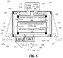
- FIG. 5 depicts a top diagrammatic view of air flow patterns 500 in example MDC 200 with left and right access doors 216 , 400 in a closed position.
- Cooling and heating unit 206 which is exteriorly coupled to volumetric container 204 , provides supply air 508 .
- Cooling and heating unit 206 can prepare supply air 508 , which can include recirculated air, outside air, or mixed air.
- Cooling and heating unit 206 warms, cools, dehumidifies, or humidifies the air, as required for operation technology (OT) components 510 and information technology (IT) components 512 in RIHS 202 .
- OT operation technology
- IT information technology
- cooling and heating unit 206 can cool air using direct evaporative cooling or mechanical cooling.
- Supply air plenum 514 of air redirection structure 212 directs pressurized supply air 508 to cold aisle 214 .
- left and right access doors 216 , 400 are sealed with door seals 516 to prevent loss of cooling air.
- Cooling and heating unit 206 draws return air 518 from hot aisle 404 via return air plenum 522 of air redirection structure 212 .
- Cooling and heating unit 206 creates a lower pressure within hot aisle 404 than cold aisle 214 .
- cooling air 523 is passively drawn through inlet/outlet air passages 525 in OT components 510 and RIHS 202 .
- Supply air 508 can be colder than the dew point temperature of outside air 527 , which can result in condensation on OT and IT components 510 , 512 if the warmer outside air 527 is allowed to enter through either of left and right access doors 216 , 400 .
- Aspects of the present disclosure avoid or mitigate the occurrence of condensation when access from the outside is made through either left or right access doors 216 , 400 , exposing the inside of the container to outside air.
- Cooling and heating unit 206 provides supply air that also air cools equipment panel 228 a - 228 b .
- Pneumatic passages 524 a - 524 c respectively provide fluid communication of supply air 526 between: (i) cold aisle 214 to equipment panel 230 a ; (ii) equipment panel 228 a to equipment panel 228 b ; and (iii) equipment panel 228 b to hot aisle 404 .
- Supply air 526 within equipment panels 228 a - 228 b can be colder than the dew point temperature of outside air 527 , which can result in condensation on IT components 528 a - 528 b if the outside air is allowed to enter through either of equipment panel access doors 230 a - 230 b .
- Aspects of the present disclosure avoid or mitigate occurrence of condensation when access is made through either equipment panel access doors 230 a - 230 b.
- FIG. 6 depicts a three-dimensional, top view of example MDC 600 that has IT compartment 629 and utility room 644 .
- IT compartment 629 includes a longitudinal row of IT components 612 between cold and hot aisles 626 , 628 .
- Dual-AHU air handling system 602 of MDC 600 includes two forward-mounted or aft-mounted AHUs 604 a , 604 b .
- AHUs 604 a , 604 b exchange cooling air with IT compartment 629 and utility room 644 via air redirection structure 606 and cold and hot aisles 626 , 628 .
- Utility room 644 includes management controller 138 that monitors and controls access door 646 to utility room 644 .
- MDC 600 is presented as an example MDC.
- aspects of the present disclosure can be applied to data centers housed in institutional buildings, larger MDCs within a single volumetric container, smaller MDCs (e.g., micro-MDCs) having one or two racks within a small volumetric container, and MDCs that include multiple volumetric enclosures.
- MDCs e.g., micro-MDCs
- MDCs that include multiple volumetric enclosures.
- FIG. 7 depicts a method 700 for cooling IT components using one of multiple modes within a data center that has a cooling system.
- the data center can be one of MDC 100 ( FIG. 1 ), 200 ( FIG. 2 ), and 600 ( FIG. 6 ) or another configuration of a data center.
- the description of method 700 is provided with general reference to the specific components illustrated within the preceding FIGS. 1-6 .
- method 700 can be implemented using management controller 138 ( FIG. 1 ) that operates environmental subsystem 144 ( FIG. 1 ).
- method 700 includes detecting, via input from air sensors, an outside ambient condition as being in one of four ranges (block 702 ).
- the four ranges are mutually exclusive and cover the full range of environmental conditions that the MDC encounters at the operational location.
- Each range is associated with a corresponding mode of operation of the cooling subsystem.
- a “normal mode” provides open loop cooling using outside air.
- a “mixed mode” provides mixing outside air with recirculated return air that is warmed by the data center.
- a “mechanical trim mode” includes mixing of outside air with recirculated return air.
- a “closed mode” recirculates all return air with cooling provided by the mechanical cooling subsystem. In one or more embodiments, fewer modes may be required for a particular location, enabling omission of certain environmental components.
- the ranges are based at least on outside air temperature and outside air humidity. In one or more embodiments, the four ranges are defined on a psychrometric chart that is tailored for the location of the data center.
- Method 700 includes determining (decision block 704 ) whether the outside ambient condition is within a first range of condition values associated with the “normal mode” of operation. In response to determining in decision block 704 that the outside ambient condition falls within the first range of condition values, method 700 includes configuring the AHU 146 ( FIG. 1 ) to perform normal mode (or open loop) cooling. The AHU 146 intakes outside air, circulates the outside air through the data center operating space, and exhausts the warmed air out of the data center (block 706 ). The AHU is configured by actuating dampers, louvers, or other mechanisms to direct air. Then, method 700 returns to block 702 to monitor the outside ambient condition.
- method 700 includes determining whether the outside ambient condition is within a second range of condition values (decision block 708 ).
- the second range corresponds to certain temperatures of outside air that are too cold and/or humidity values of outside air that are too high for direct use. In the second range, the outside air can be made acceptable in combination with a selected amount of recirculated return air that has been warmed within the data center.
- method 700 includes configuring the AHU to perform mixed mode cooling.
- the AHU intakes outside air, circulates the outside air through the data center along with a mix of recirculated, warmed air of a modulated amount (e.g., 7-97%), and exhausts the remainder of the warmed air (block 710 ).
- the range of return air that is recirculated can be varied between 0-100% with the remainder of the return air being exhausted. From block 710 , method 700 returns to block 702 as the sensors continually monitor the outside ambient condition.
- method 700 includes determining whether the outside ambient condition is within a third range of condition values (decision block 712 ).
- the third range corresponds to certain outside temperatures that are too hot and/or humidity values that are too high for direct use. In the third range, the outside air can be made acceptable by mechanical cooling.
- method 700 includes configuring the AHU to perform the mechanical trim mode of operation. The AHU intakes outside air, mechanically chills the air, circulates the chilled outside air through the data center, and exhausts the warmed air (block 714 ). Then, method 700 returns to block 702 to monitor the outside ambient condition.
- Compressor(s) of the mechanical cooling subsystem are used to directly or indirectly air condition at least a portion of the air routed through a heat exchanger.
- a chiller system is interposed between the heat exchanger and the compressor(s) of the air conditioning system. Liquid in the chiller system, such as water, is cooled by activating the compressor(s). The chilled water is circulated through the heat exchanger to cool the air.
- method 700 includes determining that the outside ambient condition is within a fourth range of condition values (block 716 ).
- the fourth range corresponds to certain combinations of outside temperatures that are too hot and/or humidity values that are too high for mechanical trim mode.
- the fourth range requires closed loop mechanical cooling.
- Method 700 includes configuring the AHU to perform closed mode operation by wholly recirculating air through the data center while mechanically chilling the air (block 718 ). Then, method 700 returns to block 702 to monitor the outside ambient condition. Closed loop cooling uses the mechanical cooling of the recirculated air.
- FIGS. 8A-8D depict a method 800 for protecting internal components of a data center from condensation due to exposure to outside air from an opened access door.
- the description of method 800 is provided with general reference to the specific components illustrated within the preceding FIGS. 1-6 .
- method 800 can be implemented using management controller 138 ( FIG. 1 ) that operates environmental subsystem 144 ( FIG. 1 ).
- management controller 138 FIG. 1
- environmental subsystem 144 FIG. 1
- method 800 includes monitoring sensor(s) that detect an outside temperature value and an outside humidity value of the outside air and an interior air temperature value of the data center (block 802 ).
- method 800 includes mechanically cooling at least a portion of supply air circulated through the data center using a cooling system to cool at least one heat-generating information technology (IT) component (block 804 ).
- the mechanical cooling is controlled by (i) determining a cooling requirement based on an operating level of the at least one heat-generating IT component; and (ii) based on the cooling requirement, setting the temperature set point of the cooling system to a second temperature value that is sufficient to handle the cooling requirement.
- Mechanical cooling can create a situation where in the interior air temperature is less than a dew point of the outside air, which is addressed by the present disclosure.
- an interior of the data center is colder than outside air that is due to outside weather instead of mechanical cooling. For example, the thermal mass within an insulated enclosure can lag behind outside thermal warming or humidity increases.
- Method 800 includes monitoring sensor(s) that detect presence of a person proximate to an access door that exposes the heat-generating IT component(s) within the data center to outside air (block 806 ). A determination is made, in decision block 808 , whether an external access request is identified to open an access door, based on presence of a person. In response to determining that the presence of a person is not detected, method 800 includes monitoring a maintenance schedule for the data center (block 810 ). A determination is made, in decision block 812 , whether an external access request is identified to open the access door based on the maintenance schedule. In response to determining that the external access request is not identified to open the access door based on the maintenance schedule, method 800 proceeds to block 802 .
- temperatures of the supply air can vary along a cold aisle within the data center.
- sensors can be spaced such that variations are not wholly or accurately sensed. To avoid condensation, the dew point temperature can be determined approximately or determined conservatively.
- method 800 includes determining whether the dew point temperature of the outside air is greater than the interior air temperature by adjusting downward an initial dew point temperature estimate by a first temperature offset, such as 2-4° C., to compensate for variability and inaccuracies-in temperature and humidity variability
- method 800 in response to determining that the dew point temperature of the outside air is greater than the interior air temperature, increasing a temperature set point of the cooling system to first temperature value that increases the interior air temperature above the dew point temperature of the outside air.
- method 800 includes presenting an indication, via the externally exposed user interface device proximate to the access door, that access to the interior of the MDC via the access door is approved (block 816 ).
- Method 800 includes unlocking the access door (block 818 ). Then method 800 proceeds to block 802 ( FIG. 8A ).
- method 800 includes determining a cooling requirement based on an operating level of the at least one heat-generating IT component (block 820 ).
- Method 800 includes determining a first temperature value that increases the interior air temperature above the dew point temperature of the outside air (block 822 ).
- a determination is made in decision block 824 , whether the first temperature value meets the cooling requirement.
- method 800 includes determining a reduced cooling requirement that is met by the cooling system at the first temperature value (block 826 ).
- method 800 includes throttling the at least one heat-generating IT component to an operating level that corresponds to the reduced cooling requirement (block 828 ).
- method 800 includes increasing a temperature set point of the cooling system to the first temperature value that increases the interior air temperature above the dew point temperature of the outside air (block 830 ).
- Method 800 can perform one or more measures to prevent or dissuade premature opening of the access door.
- Method 800 includes presenting an indication, via the externally exposed user interface device proximate to the access door, that access via the access door is not approved (block 832 ).
- method 800 includes presenting an indication of an amount of time before access will be approved (block 834 ).
- Method 800 includes maintaining the access door in a locked and closed position (block 836 ) until the time expires (e.g., the countdown timer reaches zero).
- method 800 can include determining that a scheduled maintenance period has expired or that no person is detected inside of the data center or proximate to the access door, making an external access request for either condition to no longer be valid.
- method 800 proceeds to block 802 ( FIG. 8A ).
- method 800 includes waiting for a sensing interval (block 842 ). Then method 800 proceeds to block 832 .
- method 800 includes determining a period of time required to warm the surface of heat-generating IT component(s) based on thermal mass (block 844 ).
- Method 800 includes starting a timer for the period of time (block 846 ).
- a determination is made, in decision block 848 , whether the timer tracking the period of time has expired.
- method 800 includes waiting for a sensing interval (block 850 ). Then method 800 proceeds to block 848 .
- method 800 includes presenting an indication, via the externally exposed user interface device proximate to the access door, that access via the access door is approved (block 852 ).
- Method 800 includes unlocking the access door (block 854 ).
- method 800 when possible, automatically returns operation to a mode that is most appropriate with the access door closed.
- withdrawal or invalidation of the external access request is manually triggered by a user via a user interface.
- sensors can detect that a person is no longer present either inside the MDC or proximate to the access door.
- ending of a scheduled maintenance period is detected.
- a determination is made in decision block 856 , whether the external access request is still valid.
- method 800 includes waiting for a sensing interval (block 858 ). Then method 800 proceeds to block 856 .
- method 800 includes presenting an indication, via the externally exposed user interface device proximate to the access door, that access via the access door is not approved (block 860 ).
- Method 800 includes locking the access door (block 862 ). Then method proceeds to block 802 ( FIG. 8A ).
- method 800 includes directing, by the cooling system, a portion of a supply air from a cold aisle to a hot aisle of a volumetric container via an equipment panel.
- the equipment panel is externally attached to the volumetric container of the data center such as an MDC.
- the equipment panel contains the at least one heat-generating IT component and the access door.
- method 800 includes increasing a temperature set point of the cooling system to increase the interior air temperature within the equipment panel above the dew point temperature of the outside air. Then an indication is given that access is approved, such as illuminating a green light on an equipment panel access door or by electrically unlocking the equipment panel access door.
- FIG. 9 presents a flow diagram of method 900 for facilitating user override of automatic locking of the data center.
- method 900 operates in parallel with method 800 ( FIGS. 8A-8D ).
- the description of method 900 is provided with general reference to the specific components illustrated within the preceding FIGS. 1-6 .
- method 900 can be implemented using management controller 138 ( FIG. 1 ) that operates environmental subsystem 144 ( FIG. 1 ).
- a determination is made, in decision block 902 , whether the access door is locked.
- method 900 includes waiting for a sensing interval (block 904 ). Then method 900 proceeds to block 902 .
- method 900 including monitoring a user interface device for a request to unlock the access door and for an identification credential (block 905 ).
- a determination is made, in decision block 906 , whether a user input is received via the user interface device requesting that the access door be unlocked.
- method 900 proceeds to block 904 .
- a determination is made, in decision block 908 , whether the user input includes an identification credential that is associated with someone having the authority to override the locking of the access door.
- the identification credential can be received by on one or more of: (i) reading a radio frequency identification (RFID) code on a user badge; (ii) reading a computer access card; (iii) receiving a user alphanumeric password; and (iv) performing biometric recognition (e.g., speech, face, fingerprint, retina, etc.).
- RFID radio frequency identification
- method 900 includes presenting an indication via the user interface device that a valid identification credential was not received (block 910 ). Then method 900 ends.
- method 900 includes unlocking the access door (block 912 ).
- Method 900 includes presenting an indication, via the externally exposed user interface device proximate to the access door, that access via the access door is approved (block 914 ). Then method 900 ends.
- FIG. 10 presents a flow diagram of method 1000 for automatically overriding the locking of an access door of a data center, based on a surface temperature of IT component(s).
- method 1000 operates in parallel with method 800 ( FIGS. 8A-8D ).
- the description of method 800 is provided with general reference to the specific components illustrated within the preceding FIGS. 1-6 .
- method 1000 can be implemented using management controller 138 ( FIG. 1 ) that operates environmental subsystem 144 ( FIG. 1 ).
- Method 1000 includes accessing an inventory of the at least one heat-generating IT component (block 1002 ).
- Method 1000 includes identifying, based on the inventory, particular IT components of the at least one heat-generating IT component that are designated for protecting from condensation (block 1004 ).
- Method 1000 includes determining, in decision block 1006 , whether the particular IT components are operating at or above a threshold power level that corresponds to a surface temperature of the particular IT components that is above the dew point temperature of the outside air. In response to determining that the particular IT components are operating at or above the threshold power level, method 1000 includes enabling access via the access door, based on the surface temperature of the IT components being above the dew point temperature, irrespective of the internal air temperature of the data center being below the dew point temperature (block 1008 ). Then method 1000 ends.
- method 1000 includes delaying access via the access door, based on the surface temperature of the IT components and the internal air temperature both being below the dew point temperature (block 1010 ). Then method 1000 ends.
- one or more of the methods may be embodied in a computer readable medium containing computer readable code such that a series of functional processes are performed when the computer readable code is executed on a computing device.
- certain steps of the methods are combined, performed simultaneously or in a different order, or perhaps omitted, without deviating from the scope of the disclosure.
- the method blocks are described and illustrated in a particular sequence, use of a specific sequence of functional processes represented by the blocks is not meant to imply any limitations on the disclosure. Changes may be made with regards to the sequence of processes without departing from the scope of the present disclosure. Use of a particular sequence is therefore, not to be taken in a limiting sense, and the scope of the present disclosure is defined only by the appended claims.
- These computer program instructions may be provided to a processor of a general purpose computer, special purpose computer, such as a service processor, or other programmable data processing apparatus to produce a machine, such that the instructions, which execute via the processor of the computer or other programmable data processing apparatus, performs the method for implementing the functions/acts specified in the flowchart and/or block diagram block or blocks.
- One or more of the embodiments of the disclosure described can be implementable, at least in part, using a software-controlled programmable processing device, such as a microprocessor, digital signal processor or other processing device, data processing apparatus or system.
- a computer program for configuring a programmable device, apparatus or system to implement the foregoing described methods is envisaged as an aspect of the present disclosure.
- the computer program may be embodied as source code or undergo compilation for implementation on a processing device, apparatus, or system.
- the computer program is stored on a carrier device in machine or device readable form, for example in solid-state memory, magnetic memory such as disk or tape, optically or magneto-optically readable memory such as compact disk or digital versatile disk, flash memory, etc.
- the processing device, apparatus or system utilizes the program or a part thereof to configure the processing device, apparatus, or system for operation.
- aspects of the present disclosure may be implemented using any combination of software, firmware or hardware. Accordingly, aspects of the present disclosure may take the form of an entirely hardware embodiment or an embodiment combining software (including firmware, resident software, micro-code, etc.) and hardware aspects that may all generally be referred to herein as a “circuit,” “module,” or “system.” Furthermore, aspects of the present disclosure may take the form of a computer program product embodied in one or more computer readable storage device(s) having computer readable program code embodied thereon. Any combination of one or more computer readable storage device(s) may be utilized.
- the computer readable storage device may be, for example, but not limited to, an electronic, magnetic, optical, electromagnetic, infrared, or semiconductor system, apparatus, or device, or any suitable combination of the foregoing. More specific examples (a non-exhaustive list) of the computer readable storage device would include the following: an electrical connection having one or more wires, a portable computer diskette, a hard disk, a random access memory (RAM), a read-only memory (ROM), an erasable programmable read-only memory (EPROM or Flash memory), an optical fiber, a portable compact disc read-only memory (CD-ROM), an optical storage device, a magnetic storage device, or any suitable combination of the foregoing.
- a computer readable storage device may be any tangible medium that can contain, or store a program for use by or in connection with an instruction execution system, apparatus, or device.
Landscapes
- Engineering & Computer Science (AREA)
- General Engineering & Computer Science (AREA)
- Physics & Mathematics (AREA)
- Microelectronics & Electronic Packaging (AREA)
- Computer Hardware Design (AREA)
- Thermal Sciences (AREA)
- Chemical & Material Sciences (AREA)
- Combustion & Propulsion (AREA)
- Mechanical Engineering (AREA)
- General Physics & Mathematics (AREA)
- Automation & Control Theory (AREA)
- Air Conditioning Control Device (AREA)
Abstract
Description
Claims (20)
Priority Applications (1)
| Application Number | Priority Date | Filing Date | Title |
|---|---|---|---|
| US16/740,792 US11406046B2 (en) | 2020-01-13 | 2020-01-13 | Data center cooling system that prevents condensation caused by opening external access doors |
Applications Claiming Priority (1)
| Application Number | Priority Date | Filing Date | Title |
|---|---|---|---|
| US16/740,792 US11406046B2 (en) | 2020-01-13 | 2020-01-13 | Data center cooling system that prevents condensation caused by opening external access doors |
Publications (2)
| Publication Number | Publication Date |
|---|---|
| US20210219462A1 US20210219462A1 (en) | 2021-07-15 |
| US11406046B2 true US11406046B2 (en) | 2022-08-02 |
Family
ID=76763530
Family Applications (1)
| Application Number | Title | Priority Date | Filing Date |
|---|---|---|---|
| US16/740,792 Active 2041-01-04 US11406046B2 (en) | 2020-01-13 | 2020-01-13 | Data center cooling system that prevents condensation caused by opening external access doors |
Country Status (1)
| Country | Link |
|---|---|
| US (1) | US11406046B2 (en) |
Families Citing this family (1)
| Publication number | Priority date | Publication date | Assignee | Title |
|---|---|---|---|---|
| US11352826B1 (en) * | 2021-04-27 | 2022-06-07 | Shanghai Imilab Technology Co., Ltd. | Intelligent door control system and method |
Citations (10)
| Publication number | Priority date | Publication date | Assignee | Title |
|---|---|---|---|---|
| US5651498A (en) * | 1995-07-21 | 1997-07-29 | Honeywell Inc. | Heating system with humidity control for avoiding water condensation on interior window surfaces |
| US6854284B2 (en) * | 2002-10-03 | 2005-02-15 | Hewlett-Packard Development Company, L.P. | Cooling of data centers |
| US20110186643A1 (en) * | 2010-02-03 | 2011-08-04 | Yamatake Corporation | Air-conditioning controlling method and device |
| US20110316337A1 (en) | 2010-06-29 | 2011-12-29 | Pelio W Leslie | Power generation data center |
| US8386824B2 (en) | 2008-10-21 | 2013-02-26 | Dell Products, Lp | System and method for adapting a power usage of a server during a data center cooling failure |
| US8583289B2 (en) * | 2008-02-19 | 2013-11-12 | Liebert Corporation | Climate control system for data centers |
| US8947879B2 (en) | 2010-12-16 | 2015-02-03 | Smartcube, Llc | Portable computer server enclosure |
| US9538689B2 (en) | 2013-09-25 | 2017-01-03 | Globalfoundries Inc. | Data center cooling with critical device prioritization |
| US9753520B2 (en) | 2013-12-23 | 2017-09-05 | Dell Products, L.P. | Predictive power capping and power allocation to computing nodes in a rack-based information handling system |
| US10078610B2 (en) | 2015-05-04 | 2018-09-18 | Dell Products, L.P. | System and method for optimized thermal control for management controller offline |
-
2020
- 2020-01-13 US US16/740,792 patent/US11406046B2/en active Active
Patent Citations (10)
| Publication number | Priority date | Publication date | Assignee | Title |
|---|---|---|---|---|
| US5651498A (en) * | 1995-07-21 | 1997-07-29 | Honeywell Inc. | Heating system with humidity control for avoiding water condensation on interior window surfaces |
| US6854284B2 (en) * | 2002-10-03 | 2005-02-15 | Hewlett-Packard Development Company, L.P. | Cooling of data centers |
| US8583289B2 (en) * | 2008-02-19 | 2013-11-12 | Liebert Corporation | Climate control system for data centers |
| US8386824B2 (en) | 2008-10-21 | 2013-02-26 | Dell Products, Lp | System and method for adapting a power usage of a server during a data center cooling failure |
| US20110186643A1 (en) * | 2010-02-03 | 2011-08-04 | Yamatake Corporation | Air-conditioning controlling method and device |
| US20110316337A1 (en) | 2010-06-29 | 2011-12-29 | Pelio W Leslie | Power generation data center |
| US8947879B2 (en) | 2010-12-16 | 2015-02-03 | Smartcube, Llc | Portable computer server enclosure |
| US9538689B2 (en) | 2013-09-25 | 2017-01-03 | Globalfoundries Inc. | Data center cooling with critical device prioritization |
| US9753520B2 (en) | 2013-12-23 | 2017-09-05 | Dell Products, L.P. | Predictive power capping and power allocation to computing nodes in a rack-based information handling system |
| US10078610B2 (en) | 2015-05-04 | 2018-09-18 | Dell Products, L.P. | System and method for optimized thermal control for management controller offline |
Also Published As
| Publication number | Publication date |
|---|---|
| US20210219462A1 (en) | 2021-07-15 |
Similar Documents
| Publication | Publication Date | Title |
|---|---|---|
| US11602082B2 (en) | Data center that regulates air pressure within an interior compartment | |
| US12079317B2 (en) | Modular data center | |
| US10813252B2 (en) | Tape library rack module with environmentally isolated interior | |
| US8462496B2 (en) | System and method for a modular fluid handling system with modes in a modular data center | |
| US8532838B2 (en) | System, method, and computer program product for controlling energy consumption in data centers | |
| EP2673683B1 (en) | System and method for a modular fluid handling system with modes in a modular data center | |
| US10058013B2 (en) | Environment-controlled cooling mode selection for a modular data center based on detection of contaminants and particulates in outside air | |
| US10037061B1 (en) | Multiple-stage cooling system for rack | |
| US11406046B2 (en) | Data center cooling system that prevents condensation caused by opening external access doors | |
| KR102204641B1 (en) | Independent air conditioning system for Data center | |
| US11182994B2 (en) | Facility reservation management system that controls facility devices | |
| US11039551B1 (en) | Data center that regulates supply air to multiple compartments | |
| US11681266B2 (en) | Data center management system that controls environmental conditions to facilitate operating state changes of individual equipment | |
| US11357134B2 (en) | Data center cooling system that selectively delays compressor restart of a mechanical cooling system | |
| KR102145773B1 (en) | Data Center Infrastructure Management System and method therefor | |
| CN219676650U (en) | Constant temperature and humidity article management cabinet | |
| JP2012107801A (en) | Air conditioning system | |
| US11665861B2 (en) | Edge datacenter nano enclosure with chimney and return air containment plenum | |
| WO2019226574A1 (en) | Modular data center utilizing independent data center modules | |
| US20230229212A1 (en) | Independent active cooling and heating control loop per component | |
| TWM610268U (en) | Intelligent air-conditioning cabinet and system thereof capable of being used as independent machine room | |
| KR20150003759U (en) | Closed circuit television control box | |
| CN115517030A (en) | Heat dissipation system and method |
Legal Events
| Date | Code | Title | Description |
|---|---|---|---|
| AS | Assignment |
Owner name: DELL PRODUCTS, L.P., TEXAS Free format text: ASSIGNMENT OF ASSIGNORS INTEREST;ASSIGNORS:BAILEY, MARK M.;DUNCAN, TYLER B.;SIGNING DATES FROM 20200110 TO 20200111;REEL/FRAME:051494/0244 |
|
| FEPP | Fee payment procedure |
Free format text: ENTITY STATUS SET TO UNDISCOUNTED (ORIGINAL EVENT CODE: BIG.); ENTITY STATUS OF PATENT OWNER: LARGE ENTITY |
|
| AS | Assignment |
Owner name: THE BANK OF NEW YORK MELLON TRUST COMPANY, N.A., AS COLLATERAL AGENT, TEXAS Free format text: PATENT SECURITY AGREEMENT (NOTES);ASSIGNORS:DELL PRODUCTS L.P.;EMC IP HOLDING COMPANY LLC;REEL/FRAME:052216/0758 Effective date: 20200324 |
|
| AS | Assignment |
Owner name: CREDIT SUISSE AG, CAYMAN ISLANDS BRANCH, NORTH CAROLINA Free format text: SECURITY AGREEMENT;ASSIGNORS:DELL PRODUCTS L.P.;EMC IP HOLDING COMPANY LLC;REEL/FRAME:052243/0773 Effective date: 20200326 |
|
| AS | Assignment |
Owner name: THE BANK OF NEW YORK MELLON TRUST COMPANY, N.A., TEXAS Free format text: SECURITY AGREEMENT;ASSIGNORS:CREDANT TECHNOLOGIES INC.;DELL INTERNATIONAL L.L.C.;DELL MARKETING L.P.;AND OTHERS;REEL/FRAME:053546/0001 Effective date: 20200409 |
|
| AS | Assignment |
Owner name: THE BANK OF NEW YORK MELLON TRUST COMPANY, N.A., AS COLLATERAL AGENT, TEXAS Free format text: SECURITY INTEREST;ASSIGNORS:DELL PRODUCTS L.P.;EMC CORPORATION;EMC IP HOLDING COMPANY LLC;REEL/FRAME:053311/0169 Effective date: 20200603 |
|
| STPP | Information on status: patent application and granting procedure in general |
Free format text: APPLICATION DISPATCHED FROM PREEXAM, NOT YET DOCKETED |
|
| STPP | Information on status: patent application and granting procedure in general |
Free format text: DOCKETED NEW CASE - READY FOR EXAMINATION |
|
| AS | Assignment |
Owner name: EMC IP HOLDING COMPANY LLC, TEXAS Free format text: RELEASE OF SECURITY INTEREST AF REEL 052243 FRAME 0773;ASSIGNOR:CREDIT SUISSE AG, CAYMAN ISLANDS BRANCH;REEL/FRAME:058001/0152 Effective date: 20211101 Owner name: DELL PRODUCTS L.P., TEXAS Free format text: RELEASE OF SECURITY INTEREST AF REEL 052243 FRAME 0773;ASSIGNOR:CREDIT SUISSE AG, CAYMAN ISLANDS BRANCH;REEL/FRAME:058001/0152 Effective date: 20211101 |
|
| STPP | Information on status: patent application and granting procedure in general |
Free format text: NOTICE OF ALLOWANCE MAILED -- APPLICATION RECEIVED IN OFFICE OF PUBLICATIONS |
|
| STPP | Information on status: patent application and granting procedure in general |
Free format text: AWAITING TC RESP, ISSUE FEE PAYMENT VERIFIED |
|
| AS | Assignment |
Owner name: EMC IP HOLDING COMPANY LLC, TEXAS Free format text: RELEASE OF SECURITY INTEREST IN PATENTS PREVIOUSLY RECORDED AT REEL/FRAME (053311/0169);ASSIGNOR:THE BANK OF NEW YORK MELLON TRUST COMPANY, N.A., AS NOTES COLLATERAL AGENT;REEL/FRAME:060438/0742 Effective date: 20220329 Owner name: EMC CORPORATION, MASSACHUSETTS Free format text: RELEASE OF SECURITY INTEREST IN PATENTS PREVIOUSLY RECORDED AT REEL/FRAME (053311/0169);ASSIGNOR:THE BANK OF NEW YORK MELLON TRUST COMPANY, N.A., AS NOTES COLLATERAL AGENT;REEL/FRAME:060438/0742 Effective date: 20220329 Owner name: DELL PRODUCTS L.P., TEXAS Free format text: RELEASE OF SECURITY INTEREST IN PATENTS PREVIOUSLY RECORDED AT REEL/FRAME (053311/0169);ASSIGNOR:THE BANK OF NEW YORK MELLON TRUST COMPANY, N.A., AS NOTES COLLATERAL AGENT;REEL/FRAME:060438/0742 Effective date: 20220329 Owner name: EMC IP HOLDING COMPANY LLC, TEXAS Free format text: RELEASE OF SECURITY INTEREST IN PATENTS PREVIOUSLY RECORDED AT REEL/FRAME (052216/0758);ASSIGNOR:THE BANK OF NEW YORK MELLON TRUST COMPANY, N.A., AS NOTES COLLATERAL AGENT;REEL/FRAME:060438/0680 Effective date: 20220329 Owner name: DELL PRODUCTS L.P., TEXAS Free format text: RELEASE OF SECURITY INTEREST IN PATENTS PREVIOUSLY RECORDED AT REEL/FRAME (052216/0758);ASSIGNOR:THE BANK OF NEW YORK MELLON TRUST COMPANY, N.A., AS NOTES COLLATERAL AGENT;REEL/FRAME:060438/0680 Effective date: 20220329 |
|
| STCF | Information on status: patent grant |
Free format text: PATENTED CASE |