US1140468A - Nut-lock. - Google Patents
Nut-lock. Download PDFInfo
- Publication number
- US1140468A US1140468A US81678414A US1914816784A US1140468A US 1140468 A US1140468 A US 1140468A US 81678414 A US81678414 A US 81678414A US 1914816784 A US1914816784 A US 1914816784A US 1140468 A US1140468 A US 1140468A
- Authority
- US
- United States
- Prior art keywords
- nut
- arms
- lock
- tongue
- flange
- Prior art date
- Legal status (The legal status is an assumption and is not a legal conclusion. Google has not performed a legal analysis and makes no representation as to the accuracy of the status listed.)
- Expired - Lifetime
Links
- 239000000463 material Substances 0.000 description 10
- ZOXJGFHDIHLPTG-UHFFFAOYSA-N Boron Chemical compound [B] ZOXJGFHDIHLPTG-UHFFFAOYSA-N 0.000 description 1
- 230000001154 acute effect Effects 0.000 description 1
- 229910052796 boron Inorganic materials 0.000 description 1
- 238000010276 construction Methods 0.000 description 1
- 239000002184 metal Substances 0.000 description 1
Images
Classifications
-
- F—MECHANICAL ENGINEERING; LIGHTING; HEATING; WEAPONS; BLASTING
- F16—ENGINEERING ELEMENTS AND UNITS; GENERAL MEASURES FOR PRODUCING AND MAINTAINING EFFECTIVE FUNCTIONING OF MACHINES OR INSTALLATIONS; THERMAL INSULATION IN GENERAL
- F16B—DEVICES FOR FASTENING OR SECURING CONSTRUCTIONAL ELEMENTS OR MACHINE PARTS TOGETHER, e.g. NAILS, BOLTS, CIRCLIPS, CLAMPS, CLIPS OR WEDGES; JOINTS OR JOINTING
- F16B39/00—Locking of screws, bolts or nuts
- F16B39/02—Locking of screws, bolts or nuts in which the locking takes place after screwing down
- F16B39/10—Locking of screws, bolts or nuts in which the locking takes place after screwing down by a plate, spring, wire or ring immovable with regard to the bolt or object and mainly perpendicular to the axis of the bolt
- F16B39/108—Locking of screws, bolts or nuts in which the locking takes place after screwing down by a plate, spring, wire or ring immovable with regard to the bolt or object and mainly perpendicular to the axis of the bolt with a locking washer under the nut or bolt head having at least one tongue or lug folded against the nut or bolt head, or against the object itself
-
- Y—GENERAL TAGGING OF NEW TECHNOLOGICAL DEVELOPMENTS; GENERAL TAGGING OF CROSS-SECTIONAL TECHNOLOGIES SPANNING OVER SEVERAL SECTIONS OF THE IPC; TECHNICAL SUBJECTS COVERED BY FORMER USPC CROSS-REFERENCE ART COLLECTIONS [XRACs] AND DIGESTS
- Y10—TECHNICAL SUBJECTS COVERED BY FORMER USPC
- Y10S—TECHNICAL SUBJECTS COVERED BY FORMER USPC CROSS-REFERENCE ART COLLECTIONS [XRACs] AND DIGESTS
- Y10S411/00—Expanded, threaded, driven, headed, tool-deformed, or locked-threaded fastener
- Y10S411/955—Locked bolthead or nut
- Y10S411/974—Side lock
- Y10S411/983—Inelastic tongue
Definitions
- the device forming the subject matter of this application is a nut lock and the present application discloses matter divided out of my prior application Serial No. 7 40,243 which hasnow matured into Patent No. 1,078,738.
- One object of the present invention is to provide a nut lock which may be fashioned at a trifling cost from inexpensive material.
- Another object of the invention is to provide a nut lock which may be employed without injuring the material in which the bolt and nut structure is mounted.
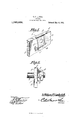
- Figure 1 is a perspective view illustrating a nut lock constructed in accordance with the present invention
- Fig. 2 is a side elevation showing the nut lock applied to the bolt.
- the nut lock herein disclosed is fashioned from a flat plate of resilient metal, slit to form a tongue 1 and to form arms 2 located along the sides of the tongue 1.
- the tongue 1 and the arms 2 are connected at one end by an angularly disposed primary flange 8, the arms 2 being connected at their outer ends by a secondary flange 4 disposed approximately parallel to the flange 3.
- the flange 3 may overhang one edge '5 of the material 6, the tongue 1 lying against one side face of the material and the arms 2 being angularly disposed with respect to the side face of the material.
- the flange 4 extends approximately at right angles to the side face of the material and ordinarily abuts thereagainst.
- the tongue 1 is provided with an opening 7, adapted to receive a bolt 8, the head of the bolt or the nut 9 thereon being held against rotation between the arms 2.
- the nut 9 is rotated to a seat on the tongue 1. Then the arms 2 are bent outwardly to assume the positions shown in Figs. 1 and 2. Subsequently, the flange 4 is bent to bear against the side face of the element 6 thereby affording a support for the arms 2.
- a sec tion of material a bolt and nut structure engaged therewith and including a rotatable element; and a nut lock comprising a tongue through which the bolt passes, the tongue being interposed between the rotatable element and the material, the tongue being provided with an angularly disposed primary flange engaging one edge of the material, there being arms projecting from the primary flange adjacent its ends, the arms engaging opposed edges of the rotatable element, the arms being disposed at an acute angle to the tongue, there being a secondary flange which connects the arms, the secondary flange being extended in the same general direction as the primary flange and being disposed at an angle to the plane defined by the arms, the secondary flange bearing against another edge of the rotatable element to constitute a means for preventing a rotation thereof, and bearing against the material to act as a brace for the arms,
- Games of this patent may be obtained for five cents each, by addressing the Commissioner of Patents Washington, D. G.
Landscapes
- Engineering & Computer Science (AREA)
- General Engineering & Computer Science (AREA)
- Mechanical Engineering (AREA)
- Connection Of Plates (AREA)
Description
w. F; LUDWICKr NUT LOCK.
APPLICATION FILED FEB. 5; 1914.
1,140,468. Patented May 25, 1915 ED STATES PATENT FIQ WILLIAM FRANKLIN LUDWIGK, 0F BEAUMONT, KANSAS, ASSIGNOR OF ONE-HALF 'IO CHARLES G. MILLER, OF ENID, OKLAHOMA.
NUT-LOCK.
1,140,468, Specification of Letters Patent. Patented May 25, 1915,
Application filed FebruaryE, 1914. Serial No. 816,784. I
To all whom it may concern Be it known that I, WILLIAM F. LUD- wIoK, a citizen of the United States, residing at Beaumont, in the county of Butler and State of Kansas, have invented a new and useful Nut-Lock, of which the following is a specification.
The device forming the subject matter of this application is a nut lock and the present application discloses matter divided out of my prior application Serial No. 7 40,243 which hasnow matured into Patent No. 1,078,738.
One object of the present invention is to provide a nut lock which may be fashioned at a trifling cost from inexpensive material.
Another object of the invention is to provide a nut lock which may be employed without injuring the material in which the bolt and nut structure is mounted.
It is within the scope of the invention to improve generally and to enhance the utility of devices of that type to which the present invention appertains.
With the above and other objects in view which will appear as the description proceeds, the invention resides in the combination and arrangement of parts and in the details of construction hereinafter described and claimed, it being understood that changes in the precise embodiment of the invention herein disclosed can be made within the scope of what is claimed without departing from the spirit of the invention.
In the accompanying drawing :Figure 1 is a perspective view illustrating a nut lock constructed in accordance with the present invention; Fig. 2 is a side elevation showing the nut lock applied to the bolt.
Referring particularly to the drawings, the nut lock herein disclosed is fashioned from a flat plate of resilient metal, slit to form a tongue 1 and to form arms 2 located along the sides of the tongue 1. The tongue 1 and the arms 2 are connected at one end by an angularly disposed primary flange 8, the arms 2 being connected at their outer ends by a secondary flange 4 disposed approximately parallel to the flange 3. The flange 3 may overhang one edge '5 of the material 6, the tongue 1 lying against one side face of the material and the arms 2 being angularly disposed with respect to the side face of the material. The flange 4 extends approximately at right angles to the side face of the material and ordinarily abuts thereagainst. The tongue 1 is provided with an opening 7, adapted to receive a bolt 8, the head of the bolt or the nut 9 thereon being held against rotation between the arms 2.
In operation, the nut 9 is rotated to a seat on the tongue 1. Then the arms 2 are bent outwardly to assume the positions shown in Figs. 1 and 2. Subsequently, the flange 4 is bent to bear against the side face of the element 6 thereby affording a support for the arms 2.
Having thus described the invention, what is claimed is In a device of the class described, a sec tion of material; a bolt and nut structure engaged therewith and including a rotatable element; and a nut lock comprising a tongue through which the bolt passes, the tongue being interposed between the rotatable element and the material, the tongue being provided with an angularly disposed primary flange engaging one edge of the material, there being arms projecting from the primary flange adjacent its ends, the arms engaging opposed edges of the rotatable element, the arms being disposed at an acute angle to the tongue, there being a secondary flange which connects the arms, the secondary flange being extended in the same general direction as the primary flange and being disposed at an angle to the plane defined by the arms, the secondary flange bearing against another edge of the rotatable element to constitute a means for preventing a rotation thereof, and bearing against the material to act as a brace for the arms,
whereby the latter will be held engaged with the first specified edges of the rotatable element.
In testimony that I claim the foregoing as my own, I have hereto afiixed my signa:
ture in the presence of two witnesses.
WILLIAM FRANKLIN LUDWIOK.
Witnesses GEO. OLDS, CHAS. Boron.
Games of this patent may be obtained for five cents each, by addressing the Commissioner of Patents Washington, D. G.
Priority Applications (1)
| Application Number | Priority Date | Filing Date | Title |
|---|---|---|---|
| US81678414A US1140468A (en) | 1914-02-05 | 1914-02-05 | Nut-lock. |
Applications Claiming Priority (1)
| Application Number | Priority Date | Filing Date | Title |
|---|---|---|---|
| US81678414A US1140468A (en) | 1914-02-05 | 1914-02-05 | Nut-lock. |
Publications (1)
| Publication Number | Publication Date |
|---|---|
| US1140468A true US1140468A (en) | 1915-05-25 |
Family
ID=3208564
Family Applications (1)
| Application Number | Title | Priority Date | Filing Date |
|---|---|---|---|
| US81678414A Expired - Lifetime US1140468A (en) | 1914-02-05 | 1914-02-05 | Nut-lock. |
Country Status (1)
| Country | Link |
|---|---|
| US (1) | US1140468A (en) |
-
1914
- 1914-02-05 US US81678414A patent/US1140468A/en not_active Expired - Lifetime
Similar Documents
| Publication | Publication Date | Title |
|---|---|---|
| US907473A (en) | Nut-lock. | |
| US951800A (en) | Nut-lock. | |
| US1140468A (en) | Nut-lock. | |
| US1228679A (en) | Lock-washer. | |
| US1543282A (en) | Lock washer | |
| US1302105A (en) | Nut-lock. | |
| US1349404A (en) | Nut-lock | |
| US174175A (en) | Improvement in nut-locks | |
| US334031A (en) | Nut-lock | |
| US1816192A (en) | Nut lock | |
| US1179305A (en) | Nut-lock. | |
| US1397820A (en) | Nut-lock | |
| US877628A (en) | Nut-lock. | |
| US498834A (en) | Nut-lock | |
| US1045797A (en) | Nut-lock. | |
| US1220207A (en) | Lock-nut. | |
| US915642A (en) | Nut-lock. | |
| US1518773A (en) | Lock washer | |
| US597737A (en) | Nut-lock | |
| US1382524A (en) | Nut-lock | |
| US1153649A (en) | Nut-lock. | |
| US943887A (en) | Nut-lock. | |
| US1165800A (en) | Nut-lock. | |
| US259899A (en) | Metallic case | |
| US1089175A (en) | Nut-lock. |