US11404654B2 - Compound containing iridium complex with aza dibenzo group and organic light emitting device comprising same - Google Patents
Compound containing iridium complex with aza dibenzo group and organic light emitting device comprising same Download PDFInfo
- Publication number
- US11404654B2 US11404654B2 US16/650,274 US201816650274A US11404654B2 US 11404654 B2 US11404654 B2 US 11404654B2 US 201816650274 A US201816650274 A US 201816650274A US 11404654 B2 US11404654 B2 US 11404654B2
- Authority
- US
- United States
- Prior art keywords
- compound
- group
- electrode
- substituted
- unsubstituted
- Prior art date
- Legal status (The legal status is an assumption and is not a legal conclusion. Google has not performed a legal analysis and makes no representation as to the accuracy of the status listed.)
- Active, expires
Links
- 0 Cc1c(C)c(C)n2->[Ir]3(c4ccccc4-c4ccccn->34)c3ccccc3-c2c1C.[1*]C.[2*]C.[3*]C Chemical compound Cc1c(C)c(C)n2->[Ir]3(c4ccccc4-c4ccccn->34)c3ccccc3-c2c1C.[1*]C.[2*]C.[3*]C 0.000 description 13
- GHKUMDMVKJEEHC-ZWUZLIBCSA-N [2H]C([2H])([2H])c1ccc2-c3ccc(C([2H])([2H])[2H])cn3->[Ir]3(c2c1)c1c(-c2ccc4c5ccccc5oc4n->32)cccc1[Si](C)(C)C.[2H]C([2H])([2H])c1ccc2-c3ccc(C([2H])([2H])[2H])cn3->[Ir]3(c2c1)c1cc([Si](C)(C)C)ccc1-c1ccc2c4ccccc4oc2n->31.[2H]C([2H])([2H])c1ccc2-c3ccc(C([2H])([2H])[2H])cn3->[Ir]3(c2c1)c1ccc([Si](C)(C)C)cc1-c1ccc2c4ccccc4oc2n->31.[2H]C([2H])([2H])c1ccc2-c3ccc(C([2H])([2H])[2H])cn3->[Ir]3(c2c1)c1cccc([Si](C)(C)C)c1-c1ccc2c4ccccc4oc2n->31 Chemical compound [2H]C([2H])([2H])c1ccc2-c3ccc(C([2H])([2H])[2H])cn3->[Ir]3(c2c1)c1c(-c2ccc4c5ccccc5oc4n->32)cccc1[Si](C)(C)C.[2H]C([2H])([2H])c1ccc2-c3ccc(C([2H])([2H])[2H])cn3->[Ir]3(c2c1)c1cc([Si](C)(C)C)ccc1-c1ccc2c4ccccc4oc2n->31.[2H]C([2H])([2H])c1ccc2-c3ccc(C([2H])([2H])[2H])cn3->[Ir]3(c2c1)c1ccc([Si](C)(C)C)cc1-c1ccc2c4ccccc4oc2n->31.[2H]C([2H])([2H])c1ccc2-c3ccc(C([2H])([2H])[2H])cn3->[Ir]3(c2c1)c1cccc([Si](C)(C)C)c1-c1ccc2c4ccccc4oc2n->31 GHKUMDMVKJEEHC-ZWUZLIBCSA-N 0.000 description 3
- QAWZOGBTCKNJIZ-UHFFFAOYSA-N C[Si](C)(C)c1c2-c3ccccc3[Ir]3(c4ccccc4-c4ccccn->34)<-n2cc2oc3ccccc3c12.C[Si](C)(C)c1ccc2-c3cc4c(cn3->[Ir]3(c5ccccc5-c5ccccn->35)c2c1)oc1ccccc14.C[Si](C)(C)c1ccc2[Ir]3(c4ccccc4-c4ccccn->34)<-n3cc4oc5ccccc5c4cc3-c2c1.C[Si](C)(C)c1cccc2-c3cc4c(cn3->[Ir]3(c5ccccc5-c5ccccn->35)c21)oc1ccccc14.C[Si](C)(C)c1cccc2[Ir]3(c4ccccc4-c4ccccn->34)<-n3cc4oc5ccccc5c4cc3-c12 Chemical compound C[Si](C)(C)c1c2-c3ccccc3[Ir]3(c4ccccc4-c4ccccn->34)<-n2cc2oc3ccccc3c12.C[Si](C)(C)c1ccc2-c3cc4c(cn3->[Ir]3(c5ccccc5-c5ccccn->35)c2c1)oc1ccccc14.C[Si](C)(C)c1ccc2[Ir]3(c4ccccc4-c4ccccn->34)<-n3cc4oc5ccccc5c4cc3-c2c1.C[Si](C)(C)c1cccc2-c3cc4c(cn3->[Ir]3(c5ccccc5-c5ccccn->35)c21)oc1ccccc14.C[Si](C)(C)c1cccc2[Ir]3(c4ccccc4-c4ccccn->34)<-n3cc4oc5ccccc5c4cc3-c12 QAWZOGBTCKNJIZ-UHFFFAOYSA-N 0.000 description 2
- TYJUJAIDOHCUQN-UHFFFAOYSA-N Cc1ccc2-c3ccc(C)cn3->[Ir]3(c2c1)c1c(-c2c4c(ccn->32)oc2ccccc24)cccc1[Si](C)(C)C.Cc1ccc2-c3ccc(C)cn3->[Ir]3(c2c1)c1cc([Si](C)(C)C)ccc1-c1c2c(ccn->31)oc1ccccc12.Cc1ccc2-c3ccc(C)cn3->[Ir]3(c2c1)c1cccc([Si](C)(C)C)c1-c1c2oc4ccccc4c2ccn->31.Cc1ccc2-c3ccc(C)cn3->[Ir]3(c2c1)c1ccccc1-c1c2c(oc4ccccc42)c([Si](C)(C)C)cn->31 Chemical compound Cc1ccc2-c3ccc(C)cn3->[Ir]3(c2c1)c1c(-c2c4c(ccn->32)oc2ccccc24)cccc1[Si](C)(C)C.Cc1ccc2-c3ccc(C)cn3->[Ir]3(c2c1)c1cc([Si](C)(C)C)ccc1-c1c2c(ccn->31)oc1ccccc12.Cc1ccc2-c3ccc(C)cn3->[Ir]3(c2c1)c1cccc([Si](C)(C)C)c1-c1c2oc4ccccc4c2ccn->31.Cc1ccc2-c3ccc(C)cn3->[Ir]3(c2c1)c1ccccc1-c1c2c(oc4ccccc42)c([Si](C)(C)C)cn->31 TYJUJAIDOHCUQN-UHFFFAOYSA-N 0.000 description 2
- OIQFJFRMOWPZJA-UHFFFAOYSA-N Cc1ccc2-c3ccc(C)cn3->[Ir]3(c2c1)c1c(-c2c4oc5ccccc5c4ccn->32)cccc1[Si](C)(C)C.Cc1ccc2-c3ccc(C)cn3->[Ir]3(c2c1)c1cc([Si](C)(C)C)ccc1-c1c2oc4ccccc4c2ccn->31.Cc1ccc2-c3ccc(C)cn3->[Ir]3(c2c1)c1ccc([Si](C)(C)C)cc1-c1c2oc4ccccc4c2ccn->31.Cc1ccc2-c3ccc(C)cn3->[Ir]3(c2c1)c1ccccc1-c1c2oc4ccccc4c2c([Si](C)(C)C)cn->31 Chemical compound Cc1ccc2-c3ccc(C)cn3->[Ir]3(c2c1)c1c(-c2c4oc5ccccc5c4ccn->32)cccc1[Si](C)(C)C.Cc1ccc2-c3ccc(C)cn3->[Ir]3(c2c1)c1cc([Si](C)(C)C)ccc1-c1c2oc4ccccc4c2ccn->31.Cc1ccc2-c3ccc(C)cn3->[Ir]3(c2c1)c1ccc([Si](C)(C)C)cc1-c1c2oc4ccccc4c2ccn->31.Cc1ccc2-c3ccc(C)cn3->[Ir]3(c2c1)c1ccccc1-c1c2oc4ccccc4c2c([Si](C)(C)C)cn->31 OIQFJFRMOWPZJA-UHFFFAOYSA-N 0.000 description 2
- QFTXGGWFQHUVDR-UHFFFAOYSA-N Cc1ccc2-c3ccc(C)cn3->[Ir]3(c2c1)c1c(-c2cc4c(cn->32)oc2ccccc24)cccc1[Si](C)(C)C.Cc1ccc2-c3ccc(C)cn3->[Ir]3(c2c1)c1cc([Si](C)(C)C)ccc1-c1cc2c(cn->31)oc1ccccc12.Cc1ccc2-c3ccc(C)cn3->[Ir]3(c2c1)c1cccc([Si](C)(C)C)c1-c1cc2c(cn->31)oc1ccccc12.Cc1ccc2-c3ccc(C)cn3->[Ir]3(c4ccc([Si](C)(C)C)cc4-c4cc5c(cn->34)oc3ccccc35)c2c1 Chemical compound Cc1ccc2-c3ccc(C)cn3->[Ir]3(c2c1)c1c(-c2cc4c(cn->32)oc2ccccc24)cccc1[Si](C)(C)C.Cc1ccc2-c3ccc(C)cn3->[Ir]3(c2c1)c1cc([Si](C)(C)C)ccc1-c1cc2c(cn->31)oc1ccccc12.Cc1ccc2-c3ccc(C)cn3->[Ir]3(c2c1)c1cccc([Si](C)(C)C)c1-c1cc2c(cn->31)oc1ccccc12.Cc1ccc2-c3ccc(C)cn3->[Ir]3(c4ccc([Si](C)(C)C)cc4-c4cc5c(cn->34)oc3ccccc35)c2c1 QFTXGGWFQHUVDR-UHFFFAOYSA-N 0.000 description 2
- YGRPSQRTSOIPSI-UHFFFAOYSA-N Cc1ccc2-c3ccc(C)cn3->[Ir]3(c2c1)c1c(-c2cc4oc5ccccc5c4cn->32)cccc1[Si](C)(C)C.Cc1ccc2-c3ccc(C)cn3->[Ir]3(c2c1)c1ccc([Si](C)(C)C)cc1-c1c2c(ccn->31)oc1ccccc12.Cc1ccc2-c3ccc(C)cn3->[Ir]3(c2c1)c1cccc([Si](C)(C)C)c1-c1c2c(ccn->31)oc1ccccc12.Cc1ccc2-c3ccc(C)cn3->[Ir]3(c2c1)c1ccccc1-c1c([Si](C)(C)C)c2oc4ccccc4c2cn->31 Chemical compound Cc1ccc2-c3ccc(C)cn3->[Ir]3(c2c1)c1c(-c2cc4oc5ccccc5c4cn->32)cccc1[Si](C)(C)C.Cc1ccc2-c3ccc(C)cn3->[Ir]3(c2c1)c1ccc([Si](C)(C)C)cc1-c1c2c(ccn->31)oc1ccccc12.Cc1ccc2-c3ccc(C)cn3->[Ir]3(c2c1)c1cccc([Si](C)(C)C)c1-c1c2c(ccn->31)oc1ccccc12.Cc1ccc2-c3ccc(C)cn3->[Ir]3(c2c1)c1ccccc1-c1c([Si](C)(C)C)c2oc4ccccc4c2cn->31 YGRPSQRTSOIPSI-UHFFFAOYSA-N 0.000 description 2
- HEMKCERMBKRIDR-UHFFFAOYSA-N Cc1ccc2-c3ccc(C)cn3->[Ir]3(c2c1)c1cc([Si](C)(C)C)ccc1-c1cc2oc4ccccc4c2cn->31.Cc1ccc2-c3ccc(C)cn3->[Ir]3(c2c1)c1cccc([Si](C)(C)C)c1-c1cc2oc4ccccc4c2cn->31.Cc1ccc2-c3ccc(C)cn3->[Ir]3(c2c1)c1ccccc1-c1c([Si](C)(C)C)c2c(cn->31)oc1ccccc12.Cc1ccc2-c3ccc(C)cn3->[Ir]3(c4ccc([Si](C)(C)C)cc4-c4cc5oc6ccccc6c5cn->34)c2c1 Chemical compound Cc1ccc2-c3ccc(C)cn3->[Ir]3(c2c1)c1cc([Si](C)(C)C)ccc1-c1cc2oc4ccccc4c2cn->31.Cc1ccc2-c3ccc(C)cn3->[Ir]3(c2c1)c1cccc([Si](C)(C)C)c1-c1cc2oc4ccccc4c2cn->31.Cc1ccc2-c3ccc(C)cn3->[Ir]3(c2c1)c1ccccc1-c1c([Si](C)(C)C)c2c(cn->31)oc1ccccc12.Cc1ccc2-c3ccc(C)cn3->[Ir]3(c4ccc([Si](C)(C)C)cc4-c4cc5oc6ccccc6c5cn->34)c2c1 HEMKCERMBKRIDR-UHFFFAOYSA-N 0.000 description 2
- FMKFQNPXJSQCLH-UHFFFAOYSA-N Cc1ccc2-c3ccccc3[Ir]3(c4c(-c5cc6c(cn->35)oc3ccccc36)cccc4[Si](C)(C)C)<-n2c1.Cc1ccc2-c3ccccc3[Ir]3(c4cc([Si](C)(C)C)ccc4-c4cc5c(cn->34)oc3ccccc35)<-n2c1.Cc1ccc2-c3ccccc3[Ir]3(c4ccc([Si](C)(C)C)cc4-c4cc5c(cn->34)oc3ccccc35)<-n2c1.Cc1ccc2-c3ccccc3[Ir]3(c4cccc([Si](C)(C)C)c4-c4cc5c(cn->34)oc3ccccc35)<-n2c1.Cc1ccc2-c3ccccc3[Ir]3(c4ccccc4-c4c([Si](C)(C)C)c5c(cn->34)oc3ccccc35)<-n2c1 Chemical compound Cc1ccc2-c3ccccc3[Ir]3(c4c(-c5cc6c(cn->35)oc3ccccc36)cccc4[Si](C)(C)C)<-n2c1.Cc1ccc2-c3ccccc3[Ir]3(c4cc([Si](C)(C)C)ccc4-c4cc5c(cn->34)oc3ccccc35)<-n2c1.Cc1ccc2-c3ccccc3[Ir]3(c4ccc([Si](C)(C)C)cc4-c4cc5c(cn->34)oc3ccccc35)<-n2c1.Cc1ccc2-c3ccccc3[Ir]3(c4cccc([Si](C)(C)C)c4-c4cc5c(cn->34)oc3ccccc35)<-n2c1.Cc1ccc2-c3ccccc3[Ir]3(c4ccccc4-c4c([Si](C)(C)C)c5c(cn->34)oc3ccccc35)<-n2c1 FMKFQNPXJSQCLH-UHFFFAOYSA-N 0.000 description 2
- XEPIIXFDPZMXHQ-ZWUZLIBCSA-N [2H]C([2H])([2H])c1ccc2-c3ccc(C([2H])([2H])[2H])cn3->[Ir]3(c2c1)c1c(-c2c4c(ccn->32)oc2ccccc24)cccc1[Si](C)(C)C.[2H]C([2H])([2H])c1ccc2-c3ccc(C([2H])([2H])[2H])cn3->[Ir]3(c2c1)c1cc([Si](C)(C)C)ccc1-c1c2c(ccn->31)oc1ccccc12.[2H]C([2H])([2H])c1ccc2-c3ccc(C([2H])([2H])[2H])cn3->[Ir]3(c2c1)c1ccc([Si](C)(C)C)cc1-c1c2c(ccn->31)oc1ccccc12.[2H]C([2H])([2H])c1ccc2-c3ccc(C([2H])([2H])[2H])cn3->[Ir]3(c2c1)c1cccc([Si](C)(C)C)c1-c1c2c(ccn->31)oc1ccccc12 Chemical compound [2H]C([2H])([2H])c1ccc2-c3ccc(C([2H])([2H])[2H])cn3->[Ir]3(c2c1)c1c(-c2c4c(ccn->32)oc2ccccc24)cccc1[Si](C)(C)C.[2H]C([2H])([2H])c1ccc2-c3ccc(C([2H])([2H])[2H])cn3->[Ir]3(c2c1)c1cc([Si](C)(C)C)ccc1-c1c2c(ccn->31)oc1ccccc12.[2H]C([2H])([2H])c1ccc2-c3ccc(C([2H])([2H])[2H])cn3->[Ir]3(c2c1)c1ccc([Si](C)(C)C)cc1-c1c2c(ccn->31)oc1ccccc12.[2H]C([2H])([2H])c1ccc2-c3ccc(C([2H])([2H])[2H])cn3->[Ir]3(c2c1)c1cccc([Si](C)(C)C)c1-c1c2c(ccn->31)oc1ccccc12 XEPIIXFDPZMXHQ-ZWUZLIBCSA-N 0.000 description 2
- LJFKVAYVEMWTPQ-SUNJZOTDSA-N [2H]C([2H])([2H])c1ccc2-c3ccc(C([2H])([2H])[2H])cn3->[Ir]3(c2c1)c1c(-c2cc4c(cn->32)oc2ccccc24)cccc1[Si](C)(C)C.[2H]C([2H])([2H])c1ccc2-c3ccc(C([2H])([2H])[2H])cn3->[Ir]3(c2c1)c1cc([Si](C)(C)C)ccc1-c1cc2c(cn->31)oc1ccccc12.[2H]C([2H])([2H])c1ccc2-c3ccc(C([2H])([2H])[2H])cn3->[Ir]3(c2c1)c1cccc([Si](C)(C)C)c1-c1cc2c(cn->31)oc1ccccc12.[2H]C([2H])([2H])c1ccc2-c3ccc(C([2H])([2H])[2H])cn3->[Ir]3(c2c1)c1ccccc1-c1c([Si](C)(C)C)c2c(cn->31)oc1ccccc12.[2H]C([2H])([2H])c1ccc2-c3ccc(C([2H])([2H])[2H])cn3->[Ir]3(c4ccc([Si](C)(C)C)cc4-c4cc5c(cn->34)oc3ccccc35)c2c1 Chemical compound [2H]C([2H])([2H])c1ccc2-c3ccc(C([2H])([2H])[2H])cn3->[Ir]3(c2c1)c1c(-c2cc4c(cn->32)oc2ccccc24)cccc1[Si](C)(C)C.[2H]C([2H])([2H])c1ccc2-c3ccc(C([2H])([2H])[2H])cn3->[Ir]3(c2c1)c1cc([Si](C)(C)C)ccc1-c1cc2c(cn->31)oc1ccccc12.[2H]C([2H])([2H])c1ccc2-c3ccc(C([2H])([2H])[2H])cn3->[Ir]3(c2c1)c1cccc([Si](C)(C)C)c1-c1cc2c(cn->31)oc1ccccc12.[2H]C([2H])([2H])c1ccc2-c3ccc(C([2H])([2H])[2H])cn3->[Ir]3(c2c1)c1ccccc1-c1c([Si](C)(C)C)c2c(cn->31)oc1ccccc12.[2H]C([2H])([2H])c1ccc2-c3ccc(C([2H])([2H])[2H])cn3->[Ir]3(c4ccc([Si](C)(C)C)cc4-c4cc5c(cn->34)oc3ccccc35)c2c1 LJFKVAYVEMWTPQ-SUNJZOTDSA-N 0.000 description 2
- SQMLQJOUFYLQFA-ZWUZLIBCSA-N [2H]C([2H])([2H])c1ccc2-c3ccc(C([2H])([2H])[2H])cn3->[Ir]3(c2c1)c1c(-c2cc4c(cn->32)oc2ccccc24)cccc1[Si](C)(C)C.[2H]C([2H])([2H])c1ccc2-c3ccc(C([2H])([2H])[2H])cn3->[Ir]3(c2c1)c1cc([Si](C)(C)C)ccc1-c1cc2c(cn->31)oc1ccccc12.[2H]C([2H])([2H])c1ccc2-c3ccc(C([2H])([2H])[2H])cn3->[Ir]3(c2c1)c1cccc([Si](C)(C)C)c1-c1cc2oc4ccccc4c2cn->31.[2H]C([2H])([2H])c1ccc2-c3ccc(C([2H])([2H])[2H])cn3->[Ir]3(c2c1)c1ccccc1-c1c([Si](C)(C)C)c2c(cn->31)oc1ccccc12 Chemical compound [2H]C([2H])([2H])c1ccc2-c3ccc(C([2H])([2H])[2H])cn3->[Ir]3(c2c1)c1c(-c2cc4c(cn->32)oc2ccccc24)cccc1[Si](C)(C)C.[2H]C([2H])([2H])c1ccc2-c3ccc(C([2H])([2H])[2H])cn3->[Ir]3(c2c1)c1cc([Si](C)(C)C)ccc1-c1cc2c(cn->31)oc1ccccc12.[2H]C([2H])([2H])c1ccc2-c3ccc(C([2H])([2H])[2H])cn3->[Ir]3(c2c1)c1cccc([Si](C)(C)C)c1-c1cc2oc4ccccc4c2cn->31.[2H]C([2H])([2H])c1ccc2-c3ccc(C([2H])([2H])[2H])cn3->[Ir]3(c2c1)c1ccccc1-c1c([Si](C)(C)C)c2c(cn->31)oc1ccccc12 SQMLQJOUFYLQFA-ZWUZLIBCSA-N 0.000 description 2
- LKWDHAUEQWEITJ-ZWUZLIBCSA-N [2H]C([2H])([2H])c1ccc2-c3ccc(C([2H])([2H])[2H])cn3->[Ir]3(c2c1)c1c(-c2cc4oc5ccccc5c4cn->32)cccc1[Si](C)(C)C.[2H]C([2H])([2H])c1ccc2-c3ccc(C([2H])([2H])[2H])cn3->[Ir]3(c2c1)c1cc([Si](C)(C)C)ccc1-c1cc2oc4ccccc4c2cn->31.[2H]C([2H])([2H])c1ccc2-c3ccc(C([2H])([2H])[2H])cn3->[Ir]3(c2c1)c1cccc([Si](C)(C)C)c1-c1cc2oc4ccccc4c2cn->31.[2H]C([2H])([2H])c1ccc2-c3ccc(C([2H])([2H])[2H])cn3->[Ir]3(c4ccc([Si](C)(C)C)cc4-c4cc5oc6ccccc6c5cn->34)c2c1 Chemical compound [2H]C([2H])([2H])c1ccc2-c3ccc(C([2H])([2H])[2H])cn3->[Ir]3(c2c1)c1c(-c2cc4oc5ccccc5c4cn->32)cccc1[Si](C)(C)C.[2H]C([2H])([2H])c1ccc2-c3ccc(C([2H])([2H])[2H])cn3->[Ir]3(c2c1)c1cc([Si](C)(C)C)ccc1-c1cc2oc4ccccc4c2cn->31.[2H]C([2H])([2H])c1ccc2-c3ccc(C([2H])([2H])[2H])cn3->[Ir]3(c2c1)c1cccc([Si](C)(C)C)c1-c1cc2oc4ccccc4c2cn->31.[2H]C([2H])([2H])c1ccc2-c3ccc(C([2H])([2H])[2H])cn3->[Ir]3(c4ccc([Si](C)(C)C)cc4-c4cc5oc6ccccc6c5cn->34)c2c1 LKWDHAUEQWEITJ-ZWUZLIBCSA-N 0.000 description 2
- XCUHEPJPWKHRFS-ZWUZLIBCSA-N [2H]C([2H])([2H])c1ccc2-c3ccc(C([2H])([2H])[2H])cn3->[Ir]3(c2c1)c1c(-c2cc4oc5ccccc5c4cn->32)cccc1[Si](C)(C)C.[2H]C([2H])([2H])c1ccc2-c3ccc(C([2H])([2H])[2H])cn3->[Ir]3(c2c1)c1cc([Si](C)(C)C)ccc1-c1cc2oc4ccccc4c2cn->31.[2H]C([2H])([2H])c1ccc2-c3ccc(C([2H])([2H])[2H])cn3->[Ir]3(c2c1)c1ccccc1-c1c([Si](C)(C)C)c2oc4ccccc4c2cn->31.[2H]C([2H])([2H])c1ccc2-c3ccc(C([2H])([2H])[2H])cn3->[Ir]3(c4ccc([Si](C)(C)C)cc4-c4cc5oc6ccccc6c5cn->34)c2c1 Chemical compound [2H]C([2H])([2H])c1ccc2-c3ccc(C([2H])([2H])[2H])cn3->[Ir]3(c2c1)c1c(-c2cc4oc5ccccc5c4cn->32)cccc1[Si](C)(C)C.[2H]C([2H])([2H])c1ccc2-c3ccc(C([2H])([2H])[2H])cn3->[Ir]3(c2c1)c1cc([Si](C)(C)C)ccc1-c1cc2oc4ccccc4c2cn->31.[2H]C([2H])([2H])c1ccc2-c3ccc(C([2H])([2H])[2H])cn3->[Ir]3(c2c1)c1ccccc1-c1c([Si](C)(C)C)c2oc4ccccc4c2cn->31.[2H]C([2H])([2H])c1ccc2-c3ccc(C([2H])([2H])[2H])cn3->[Ir]3(c4ccc([Si](C)(C)C)cc4-c4cc5oc6ccccc6c5cn->34)c2c1 XCUHEPJPWKHRFS-ZWUZLIBCSA-N 0.000 description 2
- CBKSUNRJARDIML-ZWUZLIBCSA-N [2H]C([2H])([2H])c1ccc2-c3ccc(C([2H])([2H])[2H])cn3->[Ir]3(c2c1)c1cc([Si](C)(C)C)ccc1-c1c2oc4ccccc4c2ccn->31.[2H]C([2H])([2H])c1ccc2-c3ccc(C([2H])([2H])[2H])cn3->[Ir]3(c2c1)c1ccc([Si](C)(C)C)cc1-c1c2oc4ccccc4c2ccn->31.[2H]C([2H])([2H])c1ccc2-c3ccc(C([2H])([2H])[2H])cn3->[Ir]3(c2c1)c1cccc([Si](C)(C)C)c1-c1c2oc4ccccc4c2ccn->31.[2H]C([2H])([2H])c1ccc2-c3ccc(C([2H])([2H])[2H])cn3->[Ir]3(c2c1)c1ccccc1-c1c2c(oc4ccccc42)c([Si](C)(C)C)cn->31 Chemical compound [2H]C([2H])([2H])c1ccc2-c3ccc(C([2H])([2H])[2H])cn3->[Ir]3(c2c1)c1cc([Si](C)(C)C)ccc1-c1c2oc4ccccc4c2ccn->31.[2H]C([2H])([2H])c1ccc2-c3ccc(C([2H])([2H])[2H])cn3->[Ir]3(c2c1)c1ccc([Si](C)(C)C)cc1-c1c2oc4ccccc4c2ccn->31.[2H]C([2H])([2H])c1ccc2-c3ccc(C([2H])([2H])[2H])cn3->[Ir]3(c2c1)c1cccc([Si](C)(C)C)c1-c1c2oc4ccccc4c2ccn->31.[2H]C([2H])([2H])c1ccc2-c3ccc(C([2H])([2H])[2H])cn3->[Ir]3(c2c1)c1ccccc1-c1c2c(oc4ccccc42)c([Si](C)(C)C)cn->31 CBKSUNRJARDIML-ZWUZLIBCSA-N 0.000 description 2
- JXRVQIZSGBTURS-ZCGQUQJASA-N [2H]C([2H])([2H])c1ccc2-c3ccccc3[Ir]3(c4c(-c5cc6c(cn->35)oc3ccccc36)cccc4[Si](C)(C)C)<-n2c1.[2H]C([2H])([2H])c1ccc2-c3ccccc3[Ir]3(c4cc([Si](C)(C)C)ccc4-c4cc5c(cn->34)oc3ccccc35)<-n2c1.[2H]C([2H])([2H])c1ccc2-c3ccccc3[Ir]3(c4ccc([Si](C)(C)C)cc4-c4cc5c(cn->34)oc3ccccc35)<-n2c1.[2H]C([2H])([2H])c1ccc2-c3ccccc3[Ir]3(c4cccc([Si](C)(C)C)c4-c4cc5c(cn->34)oc3ccccc35)<-n2c1 Chemical compound [2H]C([2H])([2H])c1ccc2-c3ccccc3[Ir]3(c4c(-c5cc6c(cn->35)oc3ccccc36)cccc4[Si](C)(C)C)<-n2c1.[2H]C([2H])([2H])c1ccc2-c3ccccc3[Ir]3(c4cc([Si](C)(C)C)ccc4-c4cc5c(cn->34)oc3ccccc35)<-n2c1.[2H]C([2H])([2H])c1ccc2-c3ccccc3[Ir]3(c4ccc([Si](C)(C)C)cc4-c4cc5c(cn->34)oc3ccccc35)<-n2c1.[2H]C([2H])([2H])c1ccc2-c3ccccc3[Ir]3(c4cccc([Si](C)(C)C)c4-c4cc5c(cn->34)oc3ccccc35)<-n2c1 JXRVQIZSGBTURS-ZCGQUQJASA-N 0.000 description 2
- FMKFQNPXJSQCLH-HMSQWINUSA-N [2H]C([2H])([2H])c1ccc2-c3ccccc3[Ir]3(c4c(-c5cc6c(cn->35)oc3ccccc36)cccc4[Si](C)(C)C)<-n2c1.[2H]C([2H])([2H])c1ccc2-c3ccccc3[Ir]3(c4cc([Si](C)(C)C)ccc4-c4cc5c(cn->34)oc3ccccc35)<-n2c1.[2H]C([2H])([2H])c1ccc2-c3ccccc3[Ir]3(c4ccc([Si](C)(C)C)cc4-c4cc5c(cn->34)oc3ccccc35)<-n2c1.[2H]C([2H])([2H])c1ccc2-c3ccccc3[Ir]3(c4cccc([Si](C)(C)C)c4-c4cc5c(cn->34)oc3ccccc35)<-n2c1.[2H]C([2H])([2H])c1ccc2-c3ccccc3[Ir]3(c4ccccc4-c4c([Si](C)(C)C)c5c(cn->34)oc3ccccc35)<-n2c1 Chemical compound [2H]C([2H])([2H])c1ccc2-c3ccccc3[Ir]3(c4c(-c5cc6c(cn->35)oc3ccccc36)cccc4[Si](C)(C)C)<-n2c1.[2H]C([2H])([2H])c1ccc2-c3ccccc3[Ir]3(c4cc([Si](C)(C)C)ccc4-c4cc5c(cn->34)oc3ccccc35)<-n2c1.[2H]C([2H])([2H])c1ccc2-c3ccccc3[Ir]3(c4ccc([Si](C)(C)C)cc4-c4cc5c(cn->34)oc3ccccc35)<-n2c1.[2H]C([2H])([2H])c1ccc2-c3ccccc3[Ir]3(c4cccc([Si](C)(C)C)c4-c4cc5c(cn->34)oc3ccccc35)<-n2c1.[2H]C([2H])([2H])c1ccc2-c3ccccc3[Ir]3(c4ccccc4-c4c([Si](C)(C)C)c5c(cn->34)oc3ccccc35)<-n2c1 FMKFQNPXJSQCLH-HMSQWINUSA-N 0.000 description 2
- LVDCVIMSFVKGAK-UHFFFAOYSA-H B.Brc1ccccn1.C.C1CCOC1.CO[Ir+]1(OC)c2ccccc2-c2ccccn->12.CS(=O)(=O)O[Ag].CS(=O)(=O)[O-].Cl[Ir](Cl)Cl.OB(O)c1ccccc1.c1ccc(-c2ccccn2)cc1.c1ccc2[Ir]3(<-Cl[Ir]4(<-Cl3)c3ccccc3-c3ccccn->43)<-n3ccccc3-c2c1 Chemical compound B.Brc1ccccn1.C.C1CCOC1.CO[Ir+]1(OC)c2ccccc2-c2ccccn->12.CS(=O)(=O)O[Ag].CS(=O)(=O)[O-].Cl[Ir](Cl)Cl.OB(O)c1ccccc1.c1ccc(-c2ccccn2)cc1.c1ccc2[Ir]3(<-Cl[Ir]4(<-Cl3)c3ccccc3-c3ccccn->43)<-n3ccccc3-c2c1 LVDCVIMSFVKGAK-UHFFFAOYSA-H 0.000 description 1
- KYQUABRQVXERQX-UHFFFAOYSA-N B.C#C.CO[Ir+]1(OC)c2ccccc2-c2ccccn->12.CS(=O)(=O)[O-].C[Si](C)(C)c1cccc2[Ir]3(c4ccccc4-c4ccccn->34)<-n3cc4oc5ccccc5c4cc3-c12.C[Si](C)(C)c1ccccc1-c1cc2c(cn1)oc1ccccc12 Chemical compound B.C#C.CO[Ir+]1(OC)c2ccccc2-c2ccccn->12.CS(=O)(=O)[O-].C[Si](C)(C)c1cccc2[Ir]3(c4ccccc4-c4ccccn->34)<-n3cc4oc5ccccc5c4cc3-c12.C[Si](C)(C)c1ccccc1-c1cc2c(cn1)oc1ccccc12 KYQUABRQVXERQX-UHFFFAOYSA-N 0.000 description 1
- QNOJBLAESKLPNS-UHFFFAOYSA-N B.C#CC#CC.CO[Ir+]1(OC)c2ccccc2-c2ccccn->12.CS(=O)(=O)[O-].C[Si](C)(C)c1cccc2[Ir]3(c4ccccc4-c4ccccn->34)<-n3ccc4c(oc5ccccc54)c3-c12.C[Si](C)(C)c1ccccc1-c1nccc2c1oc1ccccc12 Chemical compound B.C#CC#CC.CO[Ir+]1(OC)c2ccccc2-c2ccccn->12.CS(=O)(=O)[O-].C[Si](C)(C)c1cccc2[Ir]3(c4ccccc4-c4ccccn->34)<-n3ccc4c(oc5ccccc54)c3-c12.C[Si](C)(C)c1ccccc1-c1nccc2c1oc1ccccc12 QNOJBLAESKLPNS-UHFFFAOYSA-N 0.000 description 1
- KXXQVEPAIDLFJN-UHFFFAOYSA-N B.C#CC.CO[Ir+]1(OC)c2ccccc2-c2ccccn->12.CS(=O)(=O)[O-].C[Si](C)(C)c1cccc2[Ir]3(c4ccccc4-c4ccccn->34)<-n3cc4c(cc3-c12)oc1ccccc14.C[Si](C)(C)c1ccccc1-c1cc2oc3ccccc3c2cn1 Chemical compound B.C#CC.CO[Ir+]1(OC)c2ccccc2-c2ccccn->12.CS(=O)(=O)[O-].C[Si](C)(C)c1cccc2[Ir]3(c4ccccc4-c4ccccn->34)<-n3cc4c(cc3-c12)oc1ccccc14.C[Si](C)(C)c1ccccc1-c1cc2oc3ccccc3c2cn1 KXXQVEPAIDLFJN-UHFFFAOYSA-N 0.000 description 1
- WJOSCROFZAEFME-UHFFFAOYSA-N B.C.CO[Ir+]1(OC)c2ccccc2-c2ccccn->12.CS(=O)(=O)[O-].C[Si](C)(C)c1cccc2[Ir]3(c4ccccc4-c4ccccn->34)<-n3c(-c12)ccc1c2ccccc2oc13.C[Si](C)(C)c1ccccc1-c1ccc2c(n1)oc1ccccc12 Chemical compound B.C.CO[Ir+]1(OC)c2ccccc2-c2ccccn->12.CS(=O)(=O)[O-].C[Si](C)(C)c1cccc2[Ir]3(c4ccccc4-c4ccccn->34)<-n3c(-c12)ccc1c2ccccc2oc13.C[Si](C)(C)c1ccccc1-c1ccc2c(n1)oc1ccccc12 WJOSCROFZAEFME-UHFFFAOYSA-N 0.000 description 1
- ZYLVWVFSRSIBIO-UHFFFAOYSA-N B.CC#CC.CO[Ir+]1(OC)c2ccccc2-c2ccccn->12.CS(=O)(=O)[O-].C[Si](C)(C)c1cccc2[Ir]3(c4ccccc4-c4ccccn->34)<-n3ccc4oc5ccccc5c4c3-c12.C[Si](C)(C)c1ccccc1-c1nccc2oc3ccccc3c12 Chemical compound B.CC#CC.CO[Ir+]1(OC)c2ccccc2-c2ccccn->12.CS(=O)(=O)[O-].C[Si](C)(C)c1cccc2[Ir]3(c4ccccc4-c4ccccn->34)<-n3ccc4oc5ccccc5c4c3-c12.C[Si](C)(C)c1ccccc1-c1nccc2oc3ccccc3c12 ZYLVWVFSRSIBIO-UHFFFAOYSA-N 0.000 description 1
- ZPWRNHNOFFTRGH-IPASNCCWSA-N BB(B)B.C#C.CS(=O)(=O)[O-].C[Si](C)(C)c1ccccc1-c1cc2c(cn1)oc1ccccc12.[2H]C([2H])([2H])c1ccc2-c3ccc(C([2H])([2H])[2H])cn3->[Ir+](OC)(OC)c2c1.[2H]C([2H])([2H])c1ccc2-c3ccc(C([2H])([2H])[2H])cn3->[Ir]3(c2c1)c1cccc([Si](C)(C)C)c1-c1cc2c(cn->31)oc1ccccc12 Chemical compound BB(B)B.C#C.CS(=O)(=O)[O-].C[Si](C)(C)c1ccccc1-c1cc2c(cn1)oc1ccccc12.[2H]C([2H])([2H])c1ccc2-c3ccc(C([2H])([2H])[2H])cn3->[Ir+](OC)(OC)c2c1.[2H]C([2H])([2H])c1ccc2-c3ccc(C([2H])([2H])[2H])cn3->[Ir]3(c2c1)c1cccc([Si](C)(C)C)c1-c1cc2c(cn->31)oc1ccccc12 ZPWRNHNOFFTRGH-IPASNCCWSA-N 0.000 description 1
- FYPISVIKGBZROP-IPASNCCWSA-N BB(B)B.C#CC#CC.CS(=O)(=O)[O-].C[Si](C)(C)c1ccccc1-c1nccc2c1oc1ccccc12.[2H]C([2H])([2H])c1ccc2-c3ccc(C([2H])([2H])[2H])cn3->[Ir+](OC)(OC)c2c1.[2H]C([2H])([2H])c1ccc2-c3ccc(C([2H])([2H])[2H])cn3->[Ir]3(c2c1)c1cccc([Si](C)(C)C)c1-c1c2oc4ccccc4c2ccn->31 Chemical compound BB(B)B.C#CC#CC.CS(=O)(=O)[O-].C[Si](C)(C)c1ccccc1-c1nccc2c1oc1ccccc12.[2H]C([2H])([2H])c1ccc2-c3ccc(C([2H])([2H])[2H])cn3->[Ir+](OC)(OC)c2c1.[2H]C([2H])([2H])c1ccc2-c3ccc(C([2H])([2H])[2H])cn3->[Ir]3(c2c1)c1cccc([Si](C)(C)C)c1-c1c2oc4ccccc4c2ccn->31 FYPISVIKGBZROP-IPASNCCWSA-N 0.000 description 1
- BDIMHRNWKBAPTI-IPASNCCWSA-N BB(B)B.C#CC.CS(=O)(=O)[O-].C[Si](C)(C)c1ccccc1-c1cc2oc3ccccc3c2cn1.[2H]C([2H])([2H])c1ccc2-c3ccc(C([2H])([2H])[2H])cn3->[Ir+](OC)(OC)c2c1.[2H]C([2H])([2H])c1ccc2-c3ccc(C([2H])([2H])[2H])cn3->[Ir]3(c2c1)c1cccc([Si](C)(C)C)c1-c1cc2oc4ccccc4c2cn->31 Chemical compound BB(B)B.C#CC.CS(=O)(=O)[O-].C[Si](C)(C)c1ccccc1-c1cc2oc3ccccc3c2cn1.[2H]C([2H])([2H])c1ccc2-c3ccc(C([2H])([2H])[2H])cn3->[Ir+](OC)(OC)c2c1.[2H]C([2H])([2H])c1ccc2-c3ccc(C([2H])([2H])[2H])cn3->[Ir]3(c2c1)c1cccc([Si](C)(C)C)c1-c1cc2oc4ccccc4c2cn->31 BDIMHRNWKBAPTI-IPASNCCWSA-N 0.000 description 1
- VQVYZMUAGRMJDP-UZVKDJLESA-N BB(B)B.C.C.CS(=O)(=O)[O-].C[Si](C)(C)c1ccccc1-c1ccc2c(n1)oc1ccccc12.[2H]C([2H])([2H])c1ccc2-c3ccc(C([2H])([2H])[2H])cn3->[Ir+](OC)(OC)c2c1.[2H]C([2H])([2H])c1ccc2-c3ccc(C([2H])([2H])[2H])cn3->[Ir]3(c2c1)c1cccc([Si](C)(C)C)c1-c1ccc2c4ccccc4oc2n->31 Chemical compound BB(B)B.C.C.CS(=O)(=O)[O-].C[Si](C)(C)c1ccccc1-c1ccc2c(n1)oc1ccccc12.[2H]C([2H])([2H])c1ccc2-c3ccc(C([2H])([2H])[2H])cn3->[Ir+](OC)(OC)c2c1.[2H]C([2H])([2H])c1ccc2-c3ccc(C([2H])([2H])[2H])cn3->[Ir]3(c2c1)c1cccc([Si](C)(C)C)c1-c1ccc2c4ccccc4oc2n->31 VQVYZMUAGRMJDP-UZVKDJLESA-N 0.000 description 1
- AWZLCRDWZQQXOO-IPASNCCWSA-N BB(B)B.CC#CC.CS(=O)(=O)[O-].C[Si](C)(C)c1ccccc1-c1nccc2oc3ccccc3c12.[2H]C([2H])([2H])c1ccc2-c3ccc(C([2H])([2H])[2H])cn3->[Ir+](OC)(OC)c2c1.[2H]C([2H])([2H])c1ccc2-c3ccc(C([2H])([2H])[2H])cn3->[Ir]3(c2c1)c1cccc([Si](C)(C)C)c1-c1c2c(ccn->31)oc1ccccc12 Chemical compound BB(B)B.CC#CC.CS(=O)(=O)[O-].C[Si](C)(C)c1ccccc1-c1nccc2oc3ccccc3c12.[2H]C([2H])([2H])c1ccc2-c3ccc(C([2H])([2H])[2H])cn3->[Ir+](OC)(OC)c2c1.[2H]C([2H])([2H])c1ccc2-c3ccc(C([2H])([2H])[2H])cn3->[Ir]3(c2c1)c1cccc([Si](C)(C)C)c1-c1c2c(ccn->31)oc1ccccc12 AWZLCRDWZQQXOO-IPASNCCWSA-N 0.000 description 1
- FISUFJPEFMRWBK-WMCWWHCESA-N BB(B)B.CS(=O)(=O)[O-].[2H]C([2H])([2H])c1ccc2-c3ccc(C([2H])([2H])[2H])cn3->[Ir+](OC)(OC)c2c1 Chemical compound BB(B)B.CS(=O)(=O)[O-].[2H]C([2H])([2H])c1ccc2-c3ccc(C([2H])([2H])[2H])cn3->[Ir+](OC)(OC)c2c1 FISUFJPEFMRWBK-WMCWWHCESA-N 0.000 description 1
- HFGIJTQHFVPLNJ-UHFFFAOYSA-H BB.C.C1CCOC1.CO[Ir+]1(OC)c2ccccc2-c2ccc(C)cn->12.CS(=O)(=O)O[Ag].CS(=O)(=O)[O-].Cc1ccc(-c2ccccc2)nc1.Cc1ccc(Br)nc1.Cc1ccc2-c3ccccc3[Ir]3(<-Cl[Ir]4(<-Cl3)c3ccccc3-c3ccc(C)cn->43)<-n2c1.Cl[Ir](Cl)Cl.OB(O)c1ccccc1 Chemical compound BB.C.C1CCOC1.CO[Ir+]1(OC)c2ccccc2-c2ccc(C)cn->12.CS(=O)(=O)O[Ag].CS(=O)(=O)[O-].Cc1ccc(-c2ccccc2)nc1.Cc1ccc(Br)nc1.Cc1ccc2-c3ccccc3[Ir]3(<-Cl[Ir]4(<-Cl3)c3ccccc3-c3ccc(C)cn->43)<-n2c1.Cl[Ir](Cl)Cl.OB(O)c1ccccc1 HFGIJTQHFVPLNJ-UHFFFAOYSA-H 0.000 description 1
- CCXAMTNYKDDPLR-RBVCXXDISA-N BBB.C.C#C.CS(=O)(=O)[O-].C[Si](C)(C)c1ccccc1-c1cc2c(cn1)oc1ccccc12.[2H]C([2H])([2H])c1ccc2-c3ccccc3[Ir+](OC)(OC)<-n2c1.[2H]C([2H])([2H])c1ccc2-c3ccccc3[Ir]3(c4cccc([Si](C)(C)C)c4-c4cc5c(cn->34)oc3ccccc35)<-n2c1 Chemical compound BBB.C.C#C.CS(=O)(=O)[O-].C[Si](C)(C)c1ccccc1-c1cc2c(cn1)oc1ccccc12.[2H]C([2H])([2H])c1ccc2-c3ccccc3[Ir+](OC)(OC)<-n2c1.[2H]C([2H])([2H])c1ccc2-c3ccccc3[Ir]3(c4cccc([Si](C)(C)C)c4-c4cc5c(cn->34)oc3ccccc35)<-n2c1 CCXAMTNYKDDPLR-RBVCXXDISA-N 0.000 description 1
- ZQPSQHGSRMQHDO-RBVCXXDISA-N BBB.C.C#CC#CC.CS(=O)(=O)[O-].C[Si](C)(C)c1ccccc1-c1nccc2c1oc1ccccc12.[2H]C([2H])([2H])c1ccc2-c3ccccc3[Ir+](OC)(OC)<-n2c1.[2H]C([2H])([2H])c1ccc2-c3ccccc3[Ir]3(c4cccc([Si](C)(C)C)c4-c4c5oc6ccccc6c5ccn->34)<-n2c1 Chemical compound BBB.C.C#CC#CC.CS(=O)(=O)[O-].C[Si](C)(C)c1ccccc1-c1nccc2c1oc1ccccc12.[2H]C([2H])([2H])c1ccc2-c3ccccc3[Ir+](OC)(OC)<-n2c1.[2H]C([2H])([2H])c1ccc2-c3ccccc3[Ir]3(c4cccc([Si](C)(C)C)c4-c4c5oc6ccccc6c5ccn->34)<-n2c1 ZQPSQHGSRMQHDO-RBVCXXDISA-N 0.000 description 1
- VHZVGFUMARCMEI-RBVCXXDISA-N BBB.C.C#CC.CS(=O)(=O)[O-].C[Si](C)(C)c1ccccc1-c1cc2oc3ccccc3c2cn1.[2H]C([2H])([2H])c1ccc2-c3ccccc3[Ir+](OC)(OC)<-n2c1.[2H]C([2H])([2H])c1ccc2-c3ccccc3[Ir]3(c4cccc([Si](C)(C)C)c4-c4cc5oc6ccccc6c5cn->34)<-n2c1 Chemical compound BBB.C.C#CC.CS(=O)(=O)[O-].C[Si](C)(C)c1ccccc1-c1cc2oc3ccccc3c2cn1.[2H]C([2H])([2H])c1ccc2-c3ccccc3[Ir+](OC)(OC)<-n2c1.[2H]C([2H])([2H])c1ccc2-c3ccccc3[Ir]3(c4cccc([Si](C)(C)C)c4-c4cc5oc6ccccc6c5cn->34)<-n2c1 VHZVGFUMARCMEI-RBVCXXDISA-N 0.000 description 1
- BBJIDLNBKBGEPL-RBVCXXDISA-N BBB.C.C.CS(=O)(=O)[O-].C[Si](C)(C)c1ccccc1-c1ccc2c(n1)oc1ccccc12.[2H]C([2H])([2H])c1ccc2-c3ccccc3[Ir+](OC)(OC)<-n2c1.[2H]C([2H])([2H])c1ccc2-c3ccccc3[Ir]3(c4cccc([Si](C)(C)C)c4-c4ccc5c6ccccc6oc5n->34)<-n2c1 Chemical compound BBB.C.C.CS(=O)(=O)[O-].C[Si](C)(C)c1ccccc1-c1ccc2c(n1)oc1ccccc12.[2H]C([2H])([2H])c1ccc2-c3ccccc3[Ir+](OC)(OC)<-n2c1.[2H]C([2H])([2H])c1ccc2-c3ccccc3[Ir]3(c4cccc([Si](C)(C)C)c4-c4ccc5c6ccccc6oc5n->34)<-n2c1 BBJIDLNBKBGEPL-RBVCXXDISA-N 0.000 description 1
- QHELWFRTGIAESD-RBVCXXDISA-N BBB.C.CC#CC.CS(=O)(=O)[O-].C[Si](C)(C)c1ccccc1-c1nccc2oc3ccccc3c12.[2H]C([2H])([2H])c1ccc2-c3ccccc3[Ir+](OC)(OC)<-n2c1.[2H]C([2H])([2H])c1ccc2-c3ccccc3[Ir]3(c4cccc([Si](C)(C)C)c4-c4c5c(ccn->34)oc3ccccc35)<-n2c1 Chemical compound BBB.C.CC#CC.CS(=O)(=O)[O-].C[Si](C)(C)c1ccccc1-c1nccc2oc3ccccc3c12.[2H]C([2H])([2H])c1ccc2-c3ccccc3[Ir+](OC)(OC)<-n2c1.[2H]C([2H])([2H])c1ccc2-c3ccccc3[Ir]3(c4cccc([Si](C)(C)C)c4-c4c5c(ccn->34)oc3ccccc35)<-n2c1 QHELWFRTGIAESD-RBVCXXDISA-N 0.000 description 1
- CLWWTXAUAQFXEZ-UHFFFAOYSA-K Brc1ccccc1Br.C.C1CCOC1.C1CCOC1.C1CCOC1.CC(C)(C)ON=O.CC1(C)OB(B2OC(C)(C)C(C)(C)O2)OC1(C)C.CC1(C)OB(c2ccc3c(n2)oc2ccccc23)OC1(C)C.COc1ccccc1-c1ccc(Cl)nc1N.COc1ccccc1B(O)O.C[Si](C)(C)c1ccccc1-c1ccc2c(n1)oc1ccccc12.C[Si](C)(C)c1ccccc1Br.C[Si](C)(C)c1ccccc1Br.Cl[Ir](Cl)Cl.Clc1ccc2c(n1)oc1ccccc12.Nc1nc(Cl)ccc1Br Chemical compound Brc1ccccc1Br.C.C1CCOC1.C1CCOC1.C1CCOC1.CC(C)(C)ON=O.CC1(C)OB(B2OC(C)(C)C(C)(C)O2)OC1(C)C.CC1(C)OB(c2ccc3c(n2)oc2ccccc23)OC1(C)C.COc1ccccc1-c1ccc(Cl)nc1N.COc1ccccc1B(O)O.C[Si](C)(C)c1ccccc1-c1ccc2c(n1)oc1ccccc12.C[Si](C)(C)c1ccccc1Br.C[Si](C)(C)c1ccccc1Br.Cl[Ir](Cl)Cl.Clc1ccc2c(n1)oc1ccccc12.Nc1nc(Cl)ccc1Br CLWWTXAUAQFXEZ-UHFFFAOYSA-K 0.000 description 1
- QPPBXUZJVHZZOY-JODIDDECSA-H C#C.C1CCOC1.C1CCOC1.CC(C)(C)ON=O.CC1(C)OB(B2OC(C)(C)C(C)(C)O2)OC1(C)C.CC1(C)OB(c2cc3c(cn2)oc2ccccc23)OC1(C)C.CO[Ir+]1(OC)c2cccc([Si](C)(C)C)c2-c2cc3c(cn->12)oc1ccccc13.COc1ccccc1-c1cc(Cl)ncc1N.COc1ccccc1B(O)O.CS(=O)(=O)O[Ag].CS(=O)(=O)[O-].C[Si](C)(C)c1cccc2[Ir]3(<-Cl[Ir]4(<-Cl3)c3cccc([Si](C)(C)C)c3-c3cc5c(cn->43)oc3ccccc35)<-n3cc4oc5ccccc5c4cc3-c12.C[Si](C)(C)c1ccccc1-c1cc2c(cn1)oc1ccccc12.C[Si](C)(C)c1ccccc1Br.Cl[Ir](Cl)Cl.Clc1cc2c(cn1)oc1ccccc12.Nc1cnc(Cl)cc1Br.[2H][2H] Chemical compound C#C.C1CCOC1.C1CCOC1.CC(C)(C)ON=O.CC1(C)OB(B2OC(C)(C)C(C)(C)O2)OC1(C)C.CC1(C)OB(c2cc3c(cn2)oc2ccccc23)OC1(C)C.CO[Ir+]1(OC)c2cccc([Si](C)(C)C)c2-c2cc3c(cn->12)oc1ccccc13.COc1ccccc1-c1cc(Cl)ncc1N.COc1ccccc1B(O)O.CS(=O)(=O)O[Ag].CS(=O)(=O)[O-].C[Si](C)(C)c1cccc2[Ir]3(<-Cl[Ir]4(<-Cl3)c3cccc([Si](C)(C)C)c3-c3cc5c(cn->43)oc3ccccc35)<-n3cc4oc5ccccc5c4cc3-c12.C[Si](C)(C)c1ccccc1-c1cc2c(cn1)oc1ccccc12.C[Si](C)(C)c1ccccc1Br.Cl[Ir](Cl)Cl.Clc1cc2c(cn1)oc1ccccc12.Nc1cnc(Cl)cc1Br.[2H][2H] QPPBXUZJVHZZOY-JODIDDECSA-H 0.000 description 1
- LOWCNTAOADWYKT-CLEGWLRESA-I C#CC#CC.C1CCOC1.C1CCOC1.CC(C)(C)ON=O.CC1(C)OB(B2OC(C)(C)C(C)(C)O2)OC1(C)C.CC1(C)OB(c2nccc3c2oc2ccccc23)OC1(C)C.CO[Ir+]1(OC)c2cccc([Si](C)(C)C)c2-c2c3oc4ccccc4c3ccn->12.COc1ccccc1-c1ccnc(Cl)c1N.COc1ccccc1B(O)O.CS(=O)(=O)O[Ag].CS(=O)(=O)[O-].C[Si](C)(C)c1cccc2[Ir]3(<-Cl[Ir]4(<-Cl3)c3cccc([Si](C)(C)C)c3-c3c5oc6ccccc6c5ccn->43)<-n3ccc4c(oc5ccccc54)c3-c12.C[Si](C)(C)c1ccccc1-c1nccc2c1oc1ccccc12.C[Si](C)(C)c1ccccc1Br.Cl[Ir]Cl.Clc1nccc2c1oc1ccccc12.Nc1c(Br)ccnc1Cl.[2HH].[2H][2H].[2H][2H] Chemical compound C#CC#CC.C1CCOC1.C1CCOC1.CC(C)(C)ON=O.CC1(C)OB(B2OC(C)(C)C(C)(C)O2)OC1(C)C.CC1(C)OB(c2nccc3c2oc2ccccc23)OC1(C)C.CO[Ir+]1(OC)c2cccc([Si](C)(C)C)c2-c2c3oc4ccccc4c3ccn->12.COc1ccccc1-c1ccnc(Cl)c1N.COc1ccccc1B(O)O.CS(=O)(=O)O[Ag].CS(=O)(=O)[O-].C[Si](C)(C)c1cccc2[Ir]3(<-Cl[Ir]4(<-Cl3)c3cccc([Si](C)(C)C)c3-c3c5oc6ccccc6c5ccn->43)<-n3ccc4c(oc5ccccc54)c3-c12.C[Si](C)(C)c1ccccc1-c1nccc2c1oc1ccccc12.C[Si](C)(C)c1ccccc1Br.Cl[Ir]Cl.Clc1nccc2c1oc1ccccc12.Nc1c(Br)ccnc1Cl.[2HH].[2H][2H].[2H][2H] LOWCNTAOADWYKT-CLEGWLRESA-I 0.000 description 1
- YOEVSEDEKAHXSQ-UHFFFAOYSA-H C#CC.C1CCOC1.C1CCOC1.CC(C)(C)ON=O.CC1(C)OB(B2OC(C)(C)C(C)(C)O2)OC1(C)C.CC1(C)OB(c2cc3oc4ccccc4c3cn2)OC1(C)C.COc1ccccc1-c1cnc(Cl)cc1N.COc1ccccc1B(O)O.CS(=O)(=O)O[Ag].C[Si](C)(C)c1cccc2[Ir]3(<-Cl[Ir]4(<-Cl3)c3cccc([Si](C)(C)C)c3-c3cc5oc6ccccc6c5cn->43)<-n3cc4c(cc3-c12)oc1ccccc14.C[Si](C)(C)c1ccccc1-c1cc2oc3ccccc3c2cn1.C[Si](C)(C)c1ccccc1Br.Cl[Ir](Cl)Cl.Clc1cc2oc3ccccc3c2cn1.Nc1cc(Cl)ncc1Br Chemical compound C#CC.C1CCOC1.C1CCOC1.CC(C)(C)ON=O.CC1(C)OB(B2OC(C)(C)C(C)(C)O2)OC1(C)C.CC1(C)OB(c2cc3oc4ccccc4c3cn2)OC1(C)C.COc1ccccc1-c1cnc(Cl)cc1N.COc1ccccc1B(O)O.CS(=O)(=O)O[Ag].C[Si](C)(C)c1cccc2[Ir]3(<-Cl[Ir]4(<-Cl3)c3cccc([Si](C)(C)C)c3-c3cc5oc6ccccc6c5cn->43)<-n3cc4c(cc3-c12)oc1ccccc14.C[Si](C)(C)c1ccccc1-c1cc2oc3ccccc3c2cn1.C[Si](C)(C)c1ccccc1Br.Cl[Ir](Cl)Cl.Clc1cc2oc3ccccc3c2cn1.Nc1cc(Cl)ncc1Br YOEVSEDEKAHXSQ-UHFFFAOYSA-H 0.000 description 1
- PBIRQLAYRZVBMR-LVLRNZHGSA-N C.C.CO[Ir+]1(OC)c2cccc([Si](C)(C)C)c2-c2c3c(ccn->12)oc1ccccc13.CS(=O)(=O)[O-].C[Si](C)(C)c1cccc2[Ir]3(c4ccccc4-c4ccccn->34)<-n3ccc4oc5ccccc5c4c3-c12.[2H][2H].[2H][2H].c1ccc(-c2ccccn2)cc1 Chemical compound C.C.CO[Ir+]1(OC)c2cccc([Si](C)(C)C)c2-c2c3c(ccn->12)oc1ccccc13.CS(=O)(=O)[O-].C[Si](C)(C)c1cccc2[Ir]3(c4ccccc4-c4ccccn->34)<-n3ccc4oc5ccccc5c4c3-c12.[2H][2H].[2H][2H].c1ccc(-c2ccccn2)cc1 PBIRQLAYRZVBMR-LVLRNZHGSA-N 0.000 description 1
- XKPZSIUVGIXWCN-PSZXADNCSA-N C.C.CO[Ir+]1(OC)c2cccc([Si](C)(C)C)c2-c2ccc3c4ccccc4oc3n->12.CS(=O)(=O)[O-].C[Si](C)(C)c1cccc2[Ir]3(c4ccccc4-c4ccccn->34)<-n3c(-c12)ccc1c2ccccc2oc13.[2HH].c1ccc(-c2ccccn2)cc1 Chemical compound C.C.CO[Ir+]1(OC)c2cccc([Si](C)(C)C)c2-c2ccc3c4ccccc4oc3n->12.CS(=O)(=O)[O-].C[Si](C)(C)c1cccc2[Ir]3(c4ccccc4-c4ccccn->34)<-n3c(-c12)ccc1c2ccccc2oc13.[2HH].c1ccc(-c2ccccn2)cc1 XKPZSIUVGIXWCN-PSZXADNCSA-N 0.000 description 1
- HESPFDKZNQRWLV-SPPWOGOMSA-N C.CO[Ir+]1(OC)c2cccc([Si](C)(C)C)c2-c2c3oc4ccccc4c3ccn->12.CS(=O)(=O)[O-].C[Si](C)(C)c1cccc2[Ir]3(c4ccccc4-c4ccccn->34)<-n3ccc4c(oc5ccccc54)c3-c12.[2HH].[2H][2H].[2H][2H].c1ccc(-c2ccccn2)cc1 Chemical compound C.CO[Ir+]1(OC)c2cccc([Si](C)(C)C)c2-c2c3oc4ccccc4c3ccn->12.CS(=O)(=O)[O-].C[Si](C)(C)c1cccc2[Ir]3(c4ccccc4-c4ccccn->34)<-n3ccc4c(oc5ccccc54)c3-c12.[2HH].[2H][2H].[2H][2H].c1ccc(-c2ccccn2)cc1 HESPFDKZNQRWLV-SPPWOGOMSA-N 0.000 description 1
- XIODYANOVCYXEJ-ZKDPTIQOSA-N C.CO[Ir+]1(OC)c2cccc([Si](C)(C)C)c2-c2cc3c(cn->12)oc1ccccc13.CS(=O)(=O)[O-].C[Si](C)(C)c1cccc2[Ir]3(c4ccccc4-c4ccccn->34)<-n3cc4oc5ccccc5c4cc3-c12.[2H][2H].c1ccc(-c2ccccn2)cc1 Chemical compound C.CO[Ir+]1(OC)c2cccc([Si](C)(C)C)c2-c2cc3c(cn->12)oc1ccccc13.CS(=O)(=O)[O-].C[Si](C)(C)c1cccc2[Ir]3(c4ccccc4-c4ccccn->34)<-n3cc4oc5ccccc5c4cc3-c12.[2H][2H].c1ccc(-c2ccccn2)cc1 XIODYANOVCYXEJ-ZKDPTIQOSA-N 0.000 description 1
- LCHBFEBMGDJBNU-ZQWDXSFXSA-N C.CO[Ir+]1(OC)c2cccc([Si](C)(C)C)c2-c2cc3oc4ccccc4c3cn->12.CS(=O)(=O)[O-].C[Si](C)(C)c1cccc2[Ir]3(c4ccccc4-c4ccccn->34)<-n3cc4c(cc3-c12)oc1ccccc14.[2HH].[2H][2H].c1ccc(-c2ccccn2)cc1 Chemical compound C.CO[Ir+]1(OC)c2cccc([Si](C)(C)C)c2-c2cc3oc4ccccc4c3cn->12.CS(=O)(=O)[O-].C[Si](C)(C)c1cccc2[Ir]3(c4ccccc4-c4ccccn->34)<-n3cc4c(cc3-c12)oc1ccccc14.[2HH].[2H][2H].c1ccc(-c2ccccn2)cc1 LCHBFEBMGDJBNU-ZQWDXSFXSA-N 0.000 description 1
- WMWHZXCCIZJPPQ-PFUOXYOGSA-H C1CCOC1.C1CCOC1.CC#CC.CC(C)(C)ON=O.CC1(C)OB(B2OC(C)(C)C(C)(C)O2)OC1(C)C.CC1(C)OB(c2nccc3oc4ccccc4c23)OC1(C)C.CO[Ir+]1(OC)c2cccc([Si](C)(C)C)c2-c2c3c(ccn->12)oc1ccccc13.COc1ccccc1-c1c(N)ccnc1Cl.COc1ccccc1B(O)O.CS(=O)(=O)O[Ag].CS(=O)(=O)[O-].C[Si](C)(C)c1cccc2[Ir]3(<-Cl[Ir]4(<-Cl3)c3cccc([Si](C)(C)C)c3-c3c5c(ccn->43)oc3ccccc35)<-n3ccc4oc5ccccc5c4c3-c12.C[Si](C)(C)c1ccccc1-c1nccc2oc3ccccc3c12.C[Si](C)(C)c1ccccc1Br.Cl[Ir](Cl)Cl.Clc1nccc2oc3ccccc3c12.Nc1ccnc(Cl)c1Br.[2H][2H].[2H][2H] Chemical compound C1CCOC1.C1CCOC1.CC#CC.CC(C)(C)ON=O.CC1(C)OB(B2OC(C)(C)C(C)(C)O2)OC1(C)C.CC1(C)OB(c2nccc3oc4ccccc4c23)OC1(C)C.CO[Ir+]1(OC)c2cccc([Si](C)(C)C)c2-c2c3c(ccn->12)oc1ccccc13.COc1ccccc1-c1c(N)ccnc1Cl.COc1ccccc1B(O)O.CS(=O)(=O)O[Ag].CS(=O)(=O)[O-].C[Si](C)(C)c1cccc2[Ir]3(<-Cl[Ir]4(<-Cl3)c3cccc([Si](C)(C)C)c3-c3c5c(ccn->43)oc3ccccc35)<-n3ccc4oc5ccccc5c4c3-c12.C[Si](C)(C)c1ccccc1-c1nccc2oc3ccccc3c12.C[Si](C)(C)c1ccccc1Br.Cl[Ir](Cl)Cl.Clc1nccc2oc3ccccc3c12.Nc1ccnc(Cl)c1Br.[2H][2H].[2H][2H] WMWHZXCCIZJPPQ-PFUOXYOGSA-H 0.000 description 1
- JQOFKEWBVFTWOW-UHFFFAOYSA-N CC(=O)C(C)(C)C.CC(C)(C)C(=O)C1CCCC1.CC(C)(C)C(=O)Cc1ccccc1.CC(C)(C)C(=O)c1ccccc1.CC(C)C(=O)C(C)(C)C.CCC(=O)C(C)(C)C.[H]C(=O)C(C)(C)C Chemical compound CC(=O)C(C)(C)C.CC(C)(C)C(=O)C1CCCC1.CC(C)(C)C(=O)Cc1ccccc1.CC(C)(C)C(=O)c1ccccc1.CC(C)C(=O)C(C)(C)C.CCC(=O)C(C)(C)C.[H]C(=O)C(C)(C)C JQOFKEWBVFTWOW-UHFFFAOYSA-N 0.000 description 1
- NLRUXYIWARRWGF-UHFFFAOYSA-N CC(=O)N(C(C)=O)C(C)(C)C.CC(=O)N(C)C(=O)C(C)(C)C.CCC(=O)N(CC)C(=O)C(C)(C)C.CN(C(=O)C1CCCC1)C(=O)C(C)(C)C.CN(C(=O)c1ccccc1)C(=O)C(C)(C)C Chemical compound CC(=O)N(C(C)=O)C(C)(C)C.CC(=O)N(C)C(=O)C(C)(C)C.CCC(=O)N(CC)C(=O)C(C)(C)C.CN(C(=O)C1CCCC1)C(=O)C(C)(C)C.CN(C(=O)c1ccccc1)C(=O)C(C)(C)C NLRUXYIWARRWGF-UHFFFAOYSA-N 0.000 description 1
- XFJZWYLSJGJAQW-UHFFFAOYSA-N CC(=O)OC(C)(C)C.CC(C)(C)C(=O)OC1CCCC1.CC(C)(C)C(=O)Oc1ccccc1.CC(C)(C)OC(=O)C1CCCC1.CC(C)(C)OC(=O)c1ccccc1.CC(C)C(=O)OC(C)(C)C.CC(C)OC(=O)C(C)(C)C.CCC(=O)OC(C)(C)C.CCOC(=O)C(C)(C)C.COC(=O)C(C)(C)C Chemical compound CC(=O)OC(C)(C)C.CC(C)(C)C(=O)OC1CCCC1.CC(C)(C)C(=O)Oc1ccccc1.CC(C)(C)OC(=O)C1CCCC1.CC(C)(C)OC(=O)c1ccccc1.CC(C)C(=O)OC(C)(C)C.CC(C)OC(=O)C(C)(C)C.CCC(=O)OC(C)(C)C.CCOC(=O)C(C)(C)C.COC(=O)C(C)(C)C XFJZWYLSJGJAQW-UHFFFAOYSA-N 0.000 description 1
- FSRHTWWJVZICKT-UHFFFAOYSA-N CC1(C)c2ccccc2-c2cc3c4ccccc4n(-c4cccc(-c5nc(-c6ccccc6)nc(-c6ccc(-c7ccccc7)cc6)n5)c4)c3cc21.Cn1c(-c2ccc(-c3ccc4ccc(-c5ccc(-c6nc7ccccc7n6C)cc5)cc4c3)cc2)nc2ccccc21.c1ccc(-c2ccc(-n3c4ccccc4c4cc(-c5ccc6c(c5)c5ccccc5n6-c5ccccc5)ccc43)cc2)cc1.c1ccc(-c2nc(-c3ccccc3)nc(-c3ccc(-c4c(-c5ccc(-c6nc(-c7ccccc7)nc(-c7ccccc7)n6)cc5)c5ccccc5c5ccccc45)cc3)n2)cc1 Chemical compound CC1(C)c2ccccc2-c2cc3c4ccccc4n(-c4cccc(-c5nc(-c6ccccc6)nc(-c6ccc(-c7ccccc7)cc6)n5)c4)c3cc21.Cn1c(-c2ccc(-c3ccc4ccc(-c5ccc(-c6nc7ccccc7n6C)cc5)cc4c3)cc2)nc2ccccc21.c1ccc(-c2ccc(-n3c4ccccc4c4cc(-c5ccc6c(c5)c5ccccc5n6-c5ccccc5)ccc43)cc2)cc1.c1ccc(-c2nc(-c3ccccc3)nc(-c3ccc(-c4c(-c5ccc(-c6nc(-c7ccccc7)nc(-c7ccccc7)n6)cc5)c5ccccc5c5ccccc45)cc3)n2)cc1 FSRHTWWJVZICKT-UHFFFAOYSA-N 0.000 description 1
- PYZGNKOOYQWTTG-UHFFFAOYSA-N CC1(C)c2ccccc2-c2ccccc21.c1ccc(C2(c3ccccc3)c3ccccc3-c3ccccc32)cc1.c1ccc2c(c1)-c1ccccc1C21CCCC1.c1ccc2c(c1)-c1ccccc1C21c2ccccc2-c2ccccc21.c1ccc2c(c1)-c1ccccc1C21c2ccccc2-n2c3ccccc3c3cccc1c32 Chemical compound CC1(C)c2ccccc2-c2ccccc21.c1ccc(C2(c3ccccc3)c3ccccc3-c3ccccc32)cc1.c1ccc2c(c1)-c1ccccc1C21CCCC1.c1ccc2c(c1)-c1ccccc1C21c2ccccc2-c2ccccc21.c1ccc2c(c1)-c1ccccc1C21c2ccccc2-n2c3ccccc3c3cccc1c32 PYZGNKOOYQWTTG-UHFFFAOYSA-N 0.000 description 1
- VNXILFITNRNRIZ-KUIZRVCZSA-N CO[Ir+]1(OC)c2cccc([Si](C)(C)C)c2-c2cc3oc4ccccc4c3cn->12.CS(=O)(=O)[O-].[2HH].[2H][2H] Chemical compound CO[Ir+]1(OC)c2cccc([Si](C)(C)C)c2-c2cc3oc4ccccc4c3cn->12.CS(=O)(=O)[O-].[2HH].[2H][2H] VNXILFITNRNRIZ-KUIZRVCZSA-N 0.000 description 1
- HPGASCRVCCFTLI-MBDJGAHPSA-K CO[Ir+]1(OC)c2cccc([Si](C)(C)C)c2-c2ccc3c4ccccc4oc3n->12.CS(=O)(=O)O[Ag].CS(=O)(=O)[O-].C[Si](C)(C)c1cccc2[Ir]3(<-Cl[Ir]4(<-Cl3)c3cccc([Si](C)(C)C)c3-c3ccc5c6ccccc6oc5n->43)<-n3c(-c12)ccc1c2ccccc2oc13.[2HH] Chemical compound CO[Ir+]1(OC)c2cccc([Si](C)(C)C)c2-c2ccc3c4ccccc4oc3n->12.CS(=O)(=O)O[Ag].CS(=O)(=O)[O-].C[Si](C)(C)c1cccc2[Ir]3(<-Cl[Ir]4(<-Cl3)c3cccc([Si](C)(C)C)c3-c3ccc5c6ccccc6oc5n->43)<-n3c(-c12)ccc1c2ccccc2oc13.[2HH] HPGASCRVCCFTLI-MBDJGAHPSA-K 0.000 description 1
- IGXNOUJUGPNMES-UHFFFAOYSA-N C[Si](C)(C)c1c2-c3ccccc3[Ir]3(c4ccccc4-c4ccccn->34)<-n2cc2oc3ccccc3c12.C[Si](C)(C)c1ccc2-c3cc4c(cn3->[Ir]3(c5ccccc5-c5ccccn->35)c2c1)oc1ccccc14.C[Si](C)(C)c1cccc2-c3cc4c(cn3->[Ir]3(c5ccccc5-c5ccccn->35)c21)oc1ccccc14.Cc1ccc2-c3ccccc3[Ir]3(c4cccc([Si](C)(C)C)c4-c4cc5c(cn->34)oc3ccccc35)<-n2c1 Chemical compound C[Si](C)(C)c1c2-c3ccccc3[Ir]3(c4ccccc4-c4ccccn->34)<-n2cc2oc3ccccc3c12.C[Si](C)(C)c1ccc2-c3cc4c(cn3->[Ir]3(c5ccccc5-c5ccccn->35)c2c1)oc1ccccc14.C[Si](C)(C)c1cccc2-c3cc4c(cn3->[Ir]3(c5ccccc5-c5ccccn->35)c21)oc1ccccc14.Cc1ccc2-c3ccccc3[Ir]3(c4cccc([Si](C)(C)C)c4-c4cc5c(cn->34)oc3ccccc35)<-n2c1 IGXNOUJUGPNMES-UHFFFAOYSA-N 0.000 description 1
- UALWSELZHQZZNN-UHFFFAOYSA-N C[Si](C)(C)c1c2-c3ccccc3[Ir]3(c4ccccc4-c4ccccn->34)<-n2cc2oc3ccccc3c12.C[Si](C)(C)c1cccc2-c3cc4c(cn3->[Ir]3(c5ccccc5-c5ccccn->35)c21)oc1ccccc14.Cc1ccc2-c3ccc(C)cn3->[Ir]3(c2c1)c1ccc([Si](C)(C)C)cc1-c1ccc2c4ccccc4oc2n->31.Cc1ccc2-c3ccc(C)cn3->[Ir]3(c2c1)c1cccc([Si](C)(C)C)c1-c1ccc2c4ccccc4oc2n->31 Chemical compound C[Si](C)(C)c1c2-c3ccccc3[Ir]3(c4ccccc4-c4ccccn->34)<-n2cc2oc3ccccc3c12.C[Si](C)(C)c1cccc2-c3cc4c(cn3->[Ir]3(c5ccccc5-c5ccccn->35)c21)oc1ccccc14.Cc1ccc2-c3ccc(C)cn3->[Ir]3(c2c1)c1ccc([Si](C)(C)C)cc1-c1ccc2c4ccccc4oc2n->31.Cc1ccc2-c3ccc(C)cn3->[Ir]3(c2c1)c1cccc([Si](C)(C)C)c1-c1ccc2c4ccccc4oc2n->31 UALWSELZHQZZNN-UHFFFAOYSA-N 0.000 description 1
- QTYYFYMTBISKAK-UHFFFAOYSA-N C[Si](C)(C)c1c2-c3ccccc3[Ir]<-n2cc2c1oc1ccccc12.C[Si](C)(C)c1c2c(cc3-c4ccccc4[Ir]<-n31)oc1ccccc12.C[Si](C)(C)c1ccc2-c3cc4oc5ccccc5c4cn3->[Ir]c2c1.C[Si](C)(C)c1cccc2-c3cc4oc5ccccc5c4cn3->[Ir]c21 Chemical compound C[Si](C)(C)c1c2-c3ccccc3[Ir]<-n2cc2c1oc1ccccc12.C[Si](C)(C)c1c2c(cc3-c4ccccc4[Ir]<-n31)oc1ccccc12.C[Si](C)(C)c1ccc2-c3cc4oc5ccccc5c4cn3->[Ir]c2c1.C[Si](C)(C)c1cccc2-c3cc4oc5ccccc5c4cn3->[Ir]c21 QTYYFYMTBISKAK-UHFFFAOYSA-N 0.000 description 1
- BGRDSJSLUPDSPM-UHFFFAOYSA-N C[Si](C)(C)c1c2-c3ccccc3[Ir]<-n2cc2c1oc1ccccc12.C[Si](C)(C)c1c2oc3ccccc3c2cc2-c3ccccc3[Ir]<-n21.C[Si](C)(C)c1ccc2-c3cc4oc5ccccc5c4cn3->[Ir]c2c1.C[Si](C)(C)c1ccc2[Ir]<-n3cc4c(cc3-c2c1)oc1ccccc14.C[Si](C)(C)c1cccc2-c3cc4oc5ccccc5c4cn3->[Ir]c21.C[Si](C)(C)c1cccc2[Ir]<-n3cc4c(cc3-c21)oc1ccccc14 Chemical compound C[Si](C)(C)c1c2-c3ccccc3[Ir]<-n2cc2c1oc1ccccc12.C[Si](C)(C)c1c2oc3ccccc3c2cc2-c3ccccc3[Ir]<-n21.C[Si](C)(C)c1ccc2-c3cc4oc5ccccc5c4cn3->[Ir]c2c1.C[Si](C)(C)c1ccc2[Ir]<-n3cc4c(cc3-c2c1)oc1ccccc14.C[Si](C)(C)c1cccc2-c3cc4oc5ccccc5c4cn3->[Ir]c21.C[Si](C)(C)c1cccc2[Ir]<-n3cc4c(cc3-c21)oc1ccccc14 BGRDSJSLUPDSPM-UHFFFAOYSA-N 0.000 description 1
- HZQDEWMPGFSUMK-UHFFFAOYSA-N C[Si](C)(C)c1c2-c3ccccc3[Ir]<-n2cc2oc3ccccc3c12.C[Si](C)(C)c1c2oc3ccccc3c2cc2-c3ccccc3[Ir]<-n21.C[Si](C)(C)c1ccc2[Ir]<-n3cc4c(cc3-c2c1)oc1ccccc14.C[Si](C)(C)c1cccc2[Ir]<-n3cc4c(cc3-c21)oc1ccccc14 Chemical compound C[Si](C)(C)c1c2-c3ccccc3[Ir]<-n2cc2oc3ccccc3c12.C[Si](C)(C)c1c2oc3ccccc3c2cc2-c3ccccc3[Ir]<-n21.C[Si](C)(C)c1ccc2[Ir]<-n3cc4c(cc3-c2c1)oc1ccccc14.C[Si](C)(C)c1cccc2[Ir]<-n3cc4c(cc3-c21)oc1ccccc14 HZQDEWMPGFSUMK-UHFFFAOYSA-N 0.000 description 1
- SWTKYNZBAKOMAI-UHFFFAOYSA-N C[Si](C)(C)c1c2-c3ccccc3[Ir]<-n2cc2oc3ccccc3c12.C[Si](C)(C)c1ccc2-c3cc4c(cn3->[Ir]c2c1)oc1ccccc14.C[Si](C)(C)c1ccc2[Ir]<-n3cc4oc5ccccc5c4cc3-c2c1.C[Si](C)(C)c1cccc2-c3cc4c(cn3->[Ir]c21)oc1ccccc14.C[Si](C)(C)c1cccc2[Ir]<-n3cc4oc5ccccc5c4cc3-c21 Chemical compound C[Si](C)(C)c1c2-c3ccccc3[Ir]<-n2cc2oc3ccccc3c12.C[Si](C)(C)c1ccc2-c3cc4c(cn3->[Ir]c2c1)oc1ccccc14.C[Si](C)(C)c1ccc2[Ir]<-n3cc4oc5ccccc5c4cc3-c2c1.C[Si](C)(C)c1cccc2-c3cc4c(cn3->[Ir]c21)oc1ccccc14.C[Si](C)(C)c1cccc2[Ir]<-n3cc4oc5ccccc5c4cc3-c21 SWTKYNZBAKOMAI-UHFFFAOYSA-N 0.000 description 1
- AAQHDNBREPRMIT-UHFFFAOYSA-N C[Si](C)(C)c1c2oc3ccccc3c2cc2-c3ccccc3[Ir]<-n21.C[Si](C)(C)c1cc2oc3ccccc3c2c2-c3ccccc3[Ir]<-n12.C[Si](C)(C)c1ccc2-c3c4c(ccn3->[Ir]c2c1)oc1ccccc14.C[Si](C)(C)c1ccc2[Ir]<-n3ccc4oc5ccccc5c4c3-c2c1.C[Si](C)(C)c1cccc2-c3c4c(ccn3->[Ir]c21)oc1ccccc14.C[Si](C)(C)c1cccc2[Ir]<-n3ccc4oc5ccccc5c4c3-c21 Chemical compound C[Si](C)(C)c1c2oc3ccccc3c2cc2-c3ccccc3[Ir]<-n21.C[Si](C)(C)c1cc2oc3ccccc3c2c2-c3ccccc3[Ir]<-n12.C[Si](C)(C)c1ccc2-c3c4c(ccn3->[Ir]c2c1)oc1ccccc14.C[Si](C)(C)c1ccc2[Ir]<-n3ccc4oc5ccccc5c4c3-c2c1.C[Si](C)(C)c1cccc2-c3c4c(ccn3->[Ir]c21)oc1ccccc14.C[Si](C)(C)c1cccc2[Ir]<-n3ccc4oc5ccccc5c4c3-c21 AAQHDNBREPRMIT-UHFFFAOYSA-N 0.000 description 1
- WXANXDCTTOPVEU-WRKACUHDSA-N C[Si](C)(C)c1cc2-c3ccccc3[Ir]<-n2c2oc3ccccc3c12.C[Si](C)(C)c1cc2c3ccccc3oc2n2->[Ir]c3ccccc3-c12.C[Si](C)(C)c1ccc2-c3ccc4c5ccccc5oc4n3->[Ir]c2c1.C[Si](C)(C)c1ccc2[Ir]<-n3c(-c2c1)ccc1c2ccccc2oc13.C[Si](C)(C)c1cccc2-c3ccc4c5ccccc5oc4n3->[Ir]c21.C[Si](C)(C)c1cccc2[Ir]<-n3c(-c21)ccc1c2ccccc2oc13.[2H]C([2H])([2H])c1ccc2-c3ccc(C([2H])([2H])[2H])cn3->[Ir]3(c2c1)c1ccccc1-c1c2oc4ccccc4c2c([Si](C)(C)C)cn->31 Chemical compound C[Si](C)(C)c1cc2-c3ccccc3[Ir]<-n2c2oc3ccccc3c12.C[Si](C)(C)c1cc2c3ccccc3oc2n2->[Ir]c3ccccc3-c12.C[Si](C)(C)c1ccc2-c3ccc4c5ccccc5oc4n3->[Ir]c2c1.C[Si](C)(C)c1ccc2[Ir]<-n3c(-c2c1)ccc1c2ccccc2oc13.C[Si](C)(C)c1cccc2-c3ccc4c5ccccc5oc4n3->[Ir]c21.C[Si](C)(C)c1cccc2[Ir]<-n3c(-c21)ccc1c2ccccc2oc13.[2H]C([2H])([2H])c1ccc2-c3ccc(C([2H])([2H])[2H])cn3->[Ir]3(c2c1)c1ccccc1-c1c2oc4ccccc4c2c([Si](C)(C)C)cn->31 WXANXDCTTOPVEU-WRKACUHDSA-N 0.000 description 1
- MSHOOMWXLZTFNY-UHFFFAOYSA-N C[Si](C)(C)c1cc2-c3ccccc3[Ir]<-n2c2oc3ccccc3c12.C[Si](C)(C)c1cc2c3ccccc3oc2n2->[Ir]c3ccccc3-c12.C[Si](C)(C)c1ccc2-c3ccc4c5ccccc5oc4n3->[Ir]c2c1.C[Si](C)(C)c1cccc2-c3ccc4c5ccccc5oc4n3->[Ir]c21 Chemical compound C[Si](C)(C)c1cc2-c3ccccc3[Ir]<-n2c2oc3ccccc3c12.C[Si](C)(C)c1cc2c3ccccc3oc2n2->[Ir]c3ccccc3-c12.C[Si](C)(C)c1ccc2-c3ccc4c5ccccc5oc4n3->[Ir]c2c1.C[Si](C)(C)c1cccc2-c3ccc4c5ccccc5oc4n3->[Ir]c21 MSHOOMWXLZTFNY-UHFFFAOYSA-N 0.000 description 1
- UZXWTRVCDUESEC-UHFFFAOYSA-N C[Si](C)(C)c1cc2c(oc3ccccc32)c2-c3ccccc3[Ir]<-n12.C[Si](C)(C)c1ccc2-c3c4oc5ccccc5c4ccn3->[Ir]c2c1.C[Si](C)(C)c1cccc2-c3c4oc5ccccc5c4ccn3->[Ir]c21.C[Si](C)(C)c1cn2->[Ir]c3ccccc3-c2c2oc3ccccc3c12 Chemical compound C[Si](C)(C)c1cc2c(oc3ccccc32)c2-c3ccccc3[Ir]<-n12.C[Si](C)(C)c1ccc2-c3c4oc5ccccc5c4ccn3->[Ir]c2c1.C[Si](C)(C)c1cccc2-c3c4oc5ccccc5c4ccn3->[Ir]c21.C[Si](C)(C)c1cn2->[Ir]c3ccccc3-c2c2oc3ccccc3c12 UZXWTRVCDUESEC-UHFFFAOYSA-N 0.000 description 1
- HGLIICLEGPKTFB-UHFFFAOYSA-N C[Si](C)(C)c1cc2c(oc3ccccc32)c2-c3ccccc3[Ir]<-n12.C[Si](C)(C)c1cn2->[Ir]c3ccccc3-c2c2oc3ccccc3c12 Chemical compound C[Si](C)(C)c1cc2c(oc3ccccc32)c2-c3ccccc3[Ir]<-n12.C[Si](C)(C)c1cn2->[Ir]c3ccccc3-c2c2oc3ccccc3c12 HGLIICLEGPKTFB-UHFFFAOYSA-N 0.000 description 1
- JUQDFAGSCQNTBK-UHFFFAOYSA-N C[Si](C)(C)c1cc2oc3ccccc3c2c2-c3ccccc3[Ir]<-n12.C[Si](C)(C)c1ccc2[Ir]<-n3ccc4c(oc5ccccc54)c3-c2c1.C[Si](C)(C)c1cccc2[Ir]<-n3ccc4c(oc5ccccc54)c3-c21.C[Si](C)(C)c1cn2->[Ir]c3ccccc3-c2c2c1oc1ccccc12 Chemical compound C[Si](C)(C)c1cc2oc3ccccc3c2c2-c3ccccc3[Ir]<-n12.C[Si](C)(C)c1ccc2[Ir]<-n3ccc4c(oc5ccccc54)c3-c2c1.C[Si](C)(C)c1cccc2[Ir]<-n3ccc4c(oc5ccccc54)c3-c21.C[Si](C)(C)c1cn2->[Ir]c3ccccc3-c2c2c1oc1ccccc12 JUQDFAGSCQNTBK-UHFFFAOYSA-N 0.000 description 1
- MJSZNYFIRGZYCP-UHFFFAOYSA-N C[Si](C)(C)c1ccc2-c3c4c(ccn3->[Ir]c2c1)oc1ccccc14.C[Si](C)(C)c1ccc2[Ir]<-n3ccc4oc5ccccc5c4c3-c2c1.C[Si](C)(C)c1cccc2-c3c4c(ccn3->[Ir]c21)oc1ccccc14.C[Si](C)(C)c1cccc2[Ir]<-n3ccc4oc5ccccc5c4c3-c21 Chemical compound C[Si](C)(C)c1ccc2-c3c4c(ccn3->[Ir]c2c1)oc1ccccc14.C[Si](C)(C)c1ccc2[Ir]<-n3ccc4oc5ccccc5c4c3-c2c1.C[Si](C)(C)c1cccc2-c3c4c(ccn3->[Ir]c21)oc1ccccc14.C[Si](C)(C)c1cccc2[Ir]<-n3ccc4oc5ccccc5c4c3-c21 MJSZNYFIRGZYCP-UHFFFAOYSA-N 0.000 description 1
- LXBBIAMUGPAFHN-UHFFFAOYSA-N C[Si](C)(C)c1ccc2-c3c4oc5ccccc5c4ccn3->[Ir]c2c1.C[Si](C)(C)c1ccc2[Ir]<-n3ccc4c(oc5ccccc54)c3-c2c1.C[Si](C)(C)c1cccc2-c3c4oc5ccccc5c4ccn3->[Ir]c21.C[Si](C)(C)c1cccc2[Ir]<-n3ccc4c(oc5ccccc54)c3-c21.C[Si](C)(C)c1cn2->[Ir]c3ccccc3-c2c2c1oc1ccccc12 Chemical compound C[Si](C)(C)c1ccc2-c3c4oc5ccccc5c4ccn3->[Ir]c2c1.C[Si](C)(C)c1ccc2[Ir]<-n3ccc4c(oc5ccccc54)c3-c2c1.C[Si](C)(C)c1cccc2-c3c4oc5ccccc5c4ccn3->[Ir]c21.C[Si](C)(C)c1cccc2[Ir]<-n3ccc4c(oc5ccccc54)c3-c21.C[Si](C)(C)c1cn2->[Ir]c3ccccc3-c2c2c1oc1ccccc12 LXBBIAMUGPAFHN-UHFFFAOYSA-N 0.000 description 1
- BRBPJPOMXAJZSR-WQAQYZOTSA-N C[Si](C)(C)c1ccc2-c3cc4c(cn3->[Ir]3(c5ccccc5-c5ccccn->35)c2c1)oc1ccccc14.C[Si](C)(C)c1ccc2[Ir]3(c4ccccc4-c4ccccn->34)<-n3cc4oc5ccccc5c4cc3-c2c1.C[Si](C)(C)c1cccc2[Ir]3(c4ccccc4-c4ccccn->34)<-n3cc4oc5ccccc5c4cc3-c12.[2H]C([2H])([2H])c1ccc2-c3ccccc3[Ir]3(c4ccccc4-c4c([Si](C)(C)C)c5c(cn->34)oc3ccccc35)<-n2c1 Chemical compound C[Si](C)(C)c1ccc2-c3cc4c(cn3->[Ir]3(c5ccccc5-c5ccccn->35)c2c1)oc1ccccc14.C[Si](C)(C)c1ccc2[Ir]3(c4ccccc4-c4ccccn->34)<-n3cc4oc5ccccc5c4cc3-c2c1.C[Si](C)(C)c1cccc2[Ir]3(c4ccccc4-c4ccccn->34)<-n3cc4oc5ccccc5c4cc3-c12.[2H]C([2H])([2H])c1ccc2-c3ccccc3[Ir]3(c4ccccc4-c4c([Si](C)(C)C)c5c(cn->34)oc3ccccc35)<-n2c1 BRBPJPOMXAJZSR-WQAQYZOTSA-N 0.000 description 1
- QGCARCYIGCINBW-UHFFFAOYSA-N C[Si](C)(C)c1ccc2-c3cc4c(cn3->[Ir]c2c1)oc1ccccc14.C[Si](C)(C)c1ccc2[Ir]<-n3cc4oc5ccccc5c4cc3-c2c1.C[Si](C)(C)c1cccc2-c3cc4c(cn3->[Ir]c21)oc1ccccc14.C[Si](C)(C)c1cccc2[Ir]<-n3cc4oc5ccccc5c4cc3-c21 Chemical compound C[Si](C)(C)c1ccc2-c3cc4c(cn3->[Ir]c2c1)oc1ccccc14.C[Si](C)(C)c1ccc2[Ir]<-n3cc4oc5ccccc5c4cc3-c2c1.C[Si](C)(C)c1cccc2-c3cc4c(cn3->[Ir]c21)oc1ccccc14.C[Si](C)(C)c1cccc2[Ir]<-n3cc4oc5ccccc5c4cc3-c21 QGCARCYIGCINBW-UHFFFAOYSA-N 0.000 description 1
- HIWDUFGXEWGTGJ-UHFFFAOYSA-N C[Si](C)(C)c1ccc2[Ir]3(c4ccccc4-c4ccccn->34)<-n3cc4oc5ccccc5c4cc3-c2c1.C[Si](C)(C)c1cccc2[Ir]3(c4ccccc4-c4ccccn->34)<-n3cc4oc5ccccc5c4cc3-c12.Cc1ccc2-c3ccccc3[Ir]3(c4c(-c5cc6c(cn->35)oc3ccccc36)cccc4[Si](C)(C)C)<-n2c1.Cc1ccc2-c3ccccc3[Ir]3(c4ccccc4-c4c([Si](C)(C)C)c5c(cn->34)oc3ccccc35)<-n2c1 Chemical compound C[Si](C)(C)c1ccc2[Ir]3(c4ccccc4-c4ccccn->34)<-n3cc4oc5ccccc5c4cc3-c2c1.C[Si](C)(C)c1cccc2[Ir]3(c4ccccc4-c4ccccn->34)<-n3cc4oc5ccccc5c4cc3-c12.Cc1ccc2-c3ccccc3[Ir]3(c4c(-c5cc6c(cn->35)oc3ccccc36)cccc4[Si](C)(C)C)<-n2c1.Cc1ccc2-c3ccccc3[Ir]3(c4ccccc4-c4c([Si](C)(C)C)c5c(cn->34)oc3ccccc35)<-n2c1 HIWDUFGXEWGTGJ-UHFFFAOYSA-N 0.000 description 1
- SRRJWAAJONXHMQ-AZINUEHGSA-N C[Si](C)(C)c1ccc2[Ir]<-n3c(-c2c1)ccc1c2ccccc2oc13.C[Si](C)(C)c1cccc2[Ir]<-n3c(-c21)ccc1c2ccccc2oc13.[2H]C([2H])([2H])c1ccc2-c3ccc(C([2H])([2H])[2H])cn3->[Ir]3(c2c1)c1c(-c2c4oc5ccccc5c4ccn->32)cccc1[Si](C)(C)C.[2H]C([2H])([2H])c1ccc2-c3ccc(C([2H])([2H])[2H])cn3->[Ir]3(c2c1)c1ccccc1-c1c2oc4ccccc4c2c([Si](C)(C)C)cn->31 Chemical compound C[Si](C)(C)c1ccc2[Ir]<-n3c(-c2c1)ccc1c2ccccc2oc13.C[Si](C)(C)c1cccc2[Ir]<-n3c(-c21)ccc1c2ccccc2oc13.[2H]C([2H])([2H])c1ccc2-c3ccc(C([2H])([2H])[2H])cn3->[Ir]3(c2c1)c1c(-c2c4oc5ccccc5c4ccn->32)cccc1[Si](C)(C)C.[2H]C([2H])([2H])c1ccc2-c3ccc(C([2H])([2H])[2H])cn3->[Ir]3(c2c1)c1ccccc1-c1c2oc4ccccc4c2c([Si](C)(C)C)cn->31 SRRJWAAJONXHMQ-AZINUEHGSA-N 0.000 description 1
- FFTYMAUFVCTXID-UHFFFAOYSA-N Cc1ccc2-c3ccc(C)cn3->[Ir]3(c2c1)c1c(-c2c4c(ccn->32)oc2ccccc24)cccc1[Si](C)(C)C.Cc1ccc2-c3ccc(C)cn3->[Ir]3(c2c1)c1cc([Si](C)(C)C)ccc1-c1c2c(ccn->31)oc1ccccc12.Cc1ccc2-c3ccc(C)cn3->[Ir]3(c2c1)c1ccc([Si](C)(C)C)cc1-c1c2c(ccn->31)oc1ccccc12.Cc1ccc2-c3ccc(C)cn3->[Ir]3(c2c1)c1cccc([Si](C)(C)C)c1-c1c2c(ccn->31)oc1ccccc12.Cc1ccc2-c3ccc(C)cn3->[Ir]3(c2c1)c1ccccc1-c1c2c(oc4ccccc42)c([Si](C)(C)C)cn->31 Chemical compound Cc1ccc2-c3ccc(C)cn3->[Ir]3(c2c1)c1c(-c2c4c(ccn->32)oc2ccccc24)cccc1[Si](C)(C)C.Cc1ccc2-c3ccc(C)cn3->[Ir]3(c2c1)c1cc([Si](C)(C)C)ccc1-c1c2c(ccn->31)oc1ccccc12.Cc1ccc2-c3ccc(C)cn3->[Ir]3(c2c1)c1ccc([Si](C)(C)C)cc1-c1c2c(ccn->31)oc1ccccc12.Cc1ccc2-c3ccc(C)cn3->[Ir]3(c2c1)c1cccc([Si](C)(C)C)c1-c1c2c(ccn->31)oc1ccccc12.Cc1ccc2-c3ccc(C)cn3->[Ir]3(c2c1)c1ccccc1-c1c2c(oc4ccccc42)c([Si](C)(C)C)cn->31 FFTYMAUFVCTXID-UHFFFAOYSA-N 0.000 description 1
- ZNQYSVWKCKKCEG-UHFFFAOYSA-N Cc1ccc2-c3ccc(C)cn3->[Ir]3(c2c1)c1c(-c2c4c(ccn->32)oc2ccccc24)cccc1[Si](C)(C)C.Cc1ccc2-c3ccc(C)cn3->[Ir]3(c2c1)c1cc([Si](C)(C)C)ccc1-c1c2c(ccn->31)oc1ccccc12.Cc1ccc2-c3ccc(C)cn3->[Ir]3(c2c1)c1ccc([Si](C)(C)C)cc1-c1c2oc4ccccc4c2ccn->31.Cc1ccc2-c3ccc(C)cn3->[Ir]3(c2c1)c1cccc([Si](C)(C)C)c1-c1c2oc4ccccc4c2ccn->31.Cc1ccc2-c3ccc(C)cn3->[Ir]3(c2c1)c1ccccc1-c1c2c(oc4ccccc42)c([Si](C)(C)C)cn->31 Chemical compound Cc1ccc2-c3ccc(C)cn3->[Ir]3(c2c1)c1c(-c2c4c(ccn->32)oc2ccccc24)cccc1[Si](C)(C)C.Cc1ccc2-c3ccc(C)cn3->[Ir]3(c2c1)c1cc([Si](C)(C)C)ccc1-c1c2c(ccn->31)oc1ccccc12.Cc1ccc2-c3ccc(C)cn3->[Ir]3(c2c1)c1ccc([Si](C)(C)C)cc1-c1c2oc4ccccc4c2ccn->31.Cc1ccc2-c3ccc(C)cn3->[Ir]3(c2c1)c1cccc([Si](C)(C)C)c1-c1c2oc4ccccc4c2ccn->31.Cc1ccc2-c3ccc(C)cn3->[Ir]3(c2c1)c1ccccc1-c1c2c(oc4ccccc42)c([Si](C)(C)C)cn->31 ZNQYSVWKCKKCEG-UHFFFAOYSA-N 0.000 description 1
- JPPVBGVXCXPDRH-UHFFFAOYSA-N Cc1ccc2-c3ccc(C)cn3->[Ir]3(c2c1)c1c(-c2c4oc5ccccc5c4ccn->32)cccc1[Si](C)(C)C.Cc1ccc2-c3ccc(C)cn3->[Ir]3(c2c1)c1cc([Si](C)(C)C)ccc1-c1c2oc4ccccc4c2ccn->31.Cc1ccc2-c3ccc(C)cn3->[Ir]3(c2c1)c1ccc([Si](C)(C)C)cc1-c1c2oc4ccccc4c2ccn->31.Cc1ccc2-c3ccc(C)cn3->[Ir]3(c2c1)c1cccc([Si](C)(C)C)c1-c1c2oc4ccccc4c2ccn->31.Cc1ccc2-c3ccc(C)cn3->[Ir]3(c2c1)c1ccccc1-c1c2oc4ccccc4c2c([Si](C)(C)C)cn->31 Chemical compound Cc1ccc2-c3ccc(C)cn3->[Ir]3(c2c1)c1c(-c2c4oc5ccccc5c4ccn->32)cccc1[Si](C)(C)C.Cc1ccc2-c3ccc(C)cn3->[Ir]3(c2c1)c1cc([Si](C)(C)C)ccc1-c1c2oc4ccccc4c2ccn->31.Cc1ccc2-c3ccc(C)cn3->[Ir]3(c2c1)c1ccc([Si](C)(C)C)cc1-c1c2oc4ccccc4c2ccn->31.Cc1ccc2-c3ccc(C)cn3->[Ir]3(c2c1)c1cccc([Si](C)(C)C)c1-c1c2oc4ccccc4c2ccn->31.Cc1ccc2-c3ccc(C)cn3->[Ir]3(c2c1)c1ccccc1-c1c2oc4ccccc4c2c([Si](C)(C)C)cn->31 JPPVBGVXCXPDRH-UHFFFAOYSA-N 0.000 description 1
- MCFHULIENSPXAA-RQCLCVILSA-N Cc1ccc2-c3ccc(C)cn3->[Ir]3(c2c1)c1c(-c2c4oc5ccccc5c4ccn->32)cccc1[Si](C)(C)C.Cc1ccc2-c3ccc(C)cn3->[Ir]3(c2c1)c1cc([Si](C)(C)C)ccc1-c1c2oc4ccccc4c2ccn->31.Cc1ccc2-c3ccc(C)cn3->[Ir]3(c2c1)c1ccccc1-c1c2oc4ccccc4c2c([Si](C)(C)C)cn->31.[2H]C([2H])([2H])c1ccc2-c3ccc(C([2H])([2H])[2H])cn3->[Ir]3(c2c1)c1ccc([Si](C)(C)C)cc1-c1ccc2c4ccccc4oc2n->31.[2H]C([2H])([2H])c1ccc2-c3ccc(C([2H])([2H])[2H])cn3->[Ir]3(c2c1)c1cccc([Si](C)(C)C)c1-c1ccc2c4ccccc4oc2n->31 Chemical compound Cc1ccc2-c3ccc(C)cn3->[Ir]3(c2c1)c1c(-c2c4oc5ccccc5c4ccn->32)cccc1[Si](C)(C)C.Cc1ccc2-c3ccc(C)cn3->[Ir]3(c2c1)c1cc([Si](C)(C)C)ccc1-c1c2oc4ccccc4c2ccn->31.Cc1ccc2-c3ccc(C)cn3->[Ir]3(c2c1)c1ccccc1-c1c2oc4ccccc4c2c([Si](C)(C)C)cn->31.[2H]C([2H])([2H])c1ccc2-c3ccc(C([2H])([2H])[2H])cn3->[Ir]3(c2c1)c1ccc([Si](C)(C)C)cc1-c1ccc2c4ccccc4oc2n->31.[2H]C([2H])([2H])c1ccc2-c3ccc(C([2H])([2H])[2H])cn3->[Ir]3(c2c1)c1cccc([Si](C)(C)C)c1-c1ccc2c4ccccc4oc2n->31 MCFHULIENSPXAA-RQCLCVILSA-N 0.000 description 1
- LJFKVAYVEMWTPQ-UHFFFAOYSA-N Cc1ccc2-c3ccc(C)cn3->[Ir]3(c2c1)c1c(-c2cc4c(cn->32)oc2ccccc24)cccc1[Si](C)(C)C.Cc1ccc2-c3ccc(C)cn3->[Ir]3(c2c1)c1cc([Si](C)(C)C)ccc1-c1cc2c(cn->31)oc1ccccc12.Cc1ccc2-c3ccc(C)cn3->[Ir]3(c2c1)c1cccc([Si](C)(C)C)c1-c1cc2c(cn->31)oc1ccccc12.Cc1ccc2-c3ccc(C)cn3->[Ir]3(c2c1)c1ccccc1-c1c([Si](C)(C)C)c2c(cn->31)oc1ccccc12.Cc1ccc2-c3ccc(C)cn3->[Ir]3(c4ccc([Si](C)(C)C)cc4-c4cc5c(cn->34)oc3ccccc35)c2c1 Chemical compound Cc1ccc2-c3ccc(C)cn3->[Ir]3(c2c1)c1c(-c2cc4c(cn->32)oc2ccccc24)cccc1[Si](C)(C)C.Cc1ccc2-c3ccc(C)cn3->[Ir]3(c2c1)c1cc([Si](C)(C)C)ccc1-c1cc2c(cn->31)oc1ccccc12.Cc1ccc2-c3ccc(C)cn3->[Ir]3(c2c1)c1cccc([Si](C)(C)C)c1-c1cc2c(cn->31)oc1ccccc12.Cc1ccc2-c3ccc(C)cn3->[Ir]3(c2c1)c1ccccc1-c1c([Si](C)(C)C)c2c(cn->31)oc1ccccc12.Cc1ccc2-c3ccc(C)cn3->[Ir]3(c4ccc([Si](C)(C)C)cc4-c4cc5c(cn->34)oc3ccccc35)c2c1 LJFKVAYVEMWTPQ-UHFFFAOYSA-N 0.000 description 1
- OYFMYHWZTLQZMY-UHFFFAOYSA-N Cc1ccc2-c3ccc(C)cn3->[Ir]3(c2c1)c1c(-c2cc4c(cn->32)oc2ccccc24)cccc1[Si](C)(C)C.Cc1ccc2-c3ccc(C)cn3->[Ir]3(c2c1)c1cccc([Si](C)(C)C)c1-c1cc2oc4ccccc4c2cn->31.Cc1ccc2-c3ccc(C)cn3->[Ir]3(c2c1)c1ccccc1-c1c([Si](C)(C)C)c2c(cn->31)oc1ccccc12.Cc1ccc2-c3ccc(C)cn3->[Ir]3(c4ccc([Si](C)(C)C)cc4-c4cc5oc6ccccc6c5cn->34)c2c1 Chemical compound Cc1ccc2-c3ccc(C)cn3->[Ir]3(c2c1)c1c(-c2cc4c(cn->32)oc2ccccc24)cccc1[Si](C)(C)C.Cc1ccc2-c3ccc(C)cn3->[Ir]3(c2c1)c1cccc([Si](C)(C)C)c1-c1cc2oc4ccccc4c2cn->31.Cc1ccc2-c3ccc(C)cn3->[Ir]3(c2c1)c1ccccc1-c1c([Si](C)(C)C)c2c(cn->31)oc1ccccc12.Cc1ccc2-c3ccc(C)cn3->[Ir]3(c4ccc([Si](C)(C)C)cc4-c4cc5oc6ccccc6c5cn->34)c2c1 OYFMYHWZTLQZMY-UHFFFAOYSA-N 0.000 description 1
- MVHFSYJFHCVMDF-UHFFFAOYSA-N Cc1ccc2-c3ccc(C)cn3->[Ir]3(c2c1)c1c(-c2cc4oc5ccccc5c4cn->32)cccc1[Si](C)(C)C.Cc1ccc2-c3ccc(C)cn3->[Ir]3(c2c1)c1cc([Si](C)(C)C)ccc1-c1cc2oc4ccccc4c2cn->31.Cc1ccc2-c3ccc(C)cn3->[Ir]3(c2c1)c1ccc([Si](C)(C)C)cc1-c1c2c(ccn->31)oc1ccccc12.Cc1ccc2-c3ccc(C)cn3->[Ir]3(c2c1)c1cccc([Si](C)(C)C)c1-c1c2c(ccn->31)oc1ccccc12.Cc1ccc2-c3ccc(C)cn3->[Ir]3(c2c1)c1ccccc1-c1c([Si](C)(C)C)c2oc4ccccc4c2cn->31 Chemical compound Cc1ccc2-c3ccc(C)cn3->[Ir]3(c2c1)c1c(-c2cc4oc5ccccc5c4cn->32)cccc1[Si](C)(C)C.Cc1ccc2-c3ccc(C)cn3->[Ir]3(c2c1)c1cc([Si](C)(C)C)ccc1-c1cc2oc4ccccc4c2cn->31.Cc1ccc2-c3ccc(C)cn3->[Ir]3(c2c1)c1ccc([Si](C)(C)C)cc1-c1c2c(ccn->31)oc1ccccc12.Cc1ccc2-c3ccc(C)cn3->[Ir]3(c2c1)c1cccc([Si](C)(C)C)c1-c1c2c(ccn->31)oc1ccccc12.Cc1ccc2-c3ccc(C)cn3->[Ir]3(c2c1)c1ccccc1-c1c([Si](C)(C)C)c2oc4ccccc4c2cn->31 MVHFSYJFHCVMDF-UHFFFAOYSA-N 0.000 description 1
- CGGRRYSUINKLBN-UHFFFAOYSA-N Cc1ccc2-c3ccc(C)cn3->[Ir]3(c2c1)c1c(-c2cc4oc5ccccc5c4cn->32)cccc1[Si](C)(C)C.Cc1ccc2-c3ccc(C)cn3->[Ir]3(c2c1)c1cc([Si](C)(C)C)ccc1-c1cc2oc4ccccc4c2cn->31.Cc1ccc2-c3ccc(C)cn3->[Ir]3(c2c1)c1cccc([Si](C)(C)C)c1-c1cc2oc4ccccc4c2cn->31.Cc1ccc2-c3ccc(C)cn3->[Ir]3(c2c1)c1ccccc1-c1c([Si](C)(C)C)c2oc4ccccc4c2cn->31.Cc1ccc2-c3ccc(C)cn3->[Ir]3(c4ccc([Si](C)(C)C)cc4-c4cc5oc6ccccc6c5cn->34)c2c1 Chemical compound Cc1ccc2-c3ccc(C)cn3->[Ir]3(c2c1)c1c(-c2cc4oc5ccccc5c4cn->32)cccc1[Si](C)(C)C.Cc1ccc2-c3ccc(C)cn3->[Ir]3(c2c1)c1cc([Si](C)(C)C)ccc1-c1cc2oc4ccccc4c2cn->31.Cc1ccc2-c3ccc(C)cn3->[Ir]3(c2c1)c1cccc([Si](C)(C)C)c1-c1cc2oc4ccccc4c2cn->31.Cc1ccc2-c3ccc(C)cn3->[Ir]3(c2c1)c1ccccc1-c1c([Si](C)(C)C)c2oc4ccccc4c2cn->31.Cc1ccc2-c3ccc(C)cn3->[Ir]3(c4ccc([Si](C)(C)C)cc4-c4cc5oc6ccccc6c5cn->34)c2c1 CGGRRYSUINKLBN-UHFFFAOYSA-N 0.000 description 1
- GHKUMDMVKJEEHC-UHFFFAOYSA-N Cc1ccc2-c3ccc(C)cn3->[Ir]3(c2c1)c1c(-c2ccc4c5ccccc5oc4n->32)cccc1[Si](C)(C)C.Cc1ccc2-c3ccc(C)cn3->[Ir]3(c2c1)c1cc([Si](C)(C)C)ccc1-c1ccc2c4ccccc4oc2n->31.Cc1ccc2-c3ccc(C)cn3->[Ir]3(c2c1)c1ccc([Si](C)(C)C)cc1-c1ccc2c4ccccc4oc2n->31.Cc1ccc2-c3ccc(C)cn3->[Ir]3(c2c1)c1cccc([Si](C)(C)C)c1-c1ccc2c4ccccc4oc2n->31 Chemical compound Cc1ccc2-c3ccc(C)cn3->[Ir]3(c2c1)c1c(-c2ccc4c5ccccc5oc4n->32)cccc1[Si](C)(C)C.Cc1ccc2-c3ccc(C)cn3->[Ir]3(c2c1)c1cc([Si](C)(C)C)ccc1-c1ccc2c4ccccc4oc2n->31.Cc1ccc2-c3ccc(C)cn3->[Ir]3(c2c1)c1ccc([Si](C)(C)C)cc1-c1ccc2c4ccccc4oc2n->31.Cc1ccc2-c3ccc(C)cn3->[Ir]3(c2c1)c1cccc([Si](C)(C)C)c1-c1ccc2c4ccccc4oc2n->31 GHKUMDMVKJEEHC-UHFFFAOYSA-N 0.000 description 1
- YAJWESBBSXMGEL-UHFFFAOYSA-N Cc1ccc2-c3ccc(C)cn3->[Ir]3(c2c1)c1c(-c2ccc4c5ccccc5oc4n->32)cccc1[Si](C)(C)C.Cc1ccc2-c3ccc(C)cn3->[Ir]3(c2c1)c1cc([Si](C)(C)C)ccc1-c1ccc2c4ccccc4oc2n->31.Cc1ccc2-c3ccc(C)cn3->[Ir]3(c2c1)c1ccc([Si](C)(C)C)cc1-c1ccc2c4ccccc4oc2n->31.Cc1ccc2-c3ccc(C)cn3->[Ir]3(c2c1)c1cccc([Si](C)(C)C)c1-c1ccc2c4ccccc4oc2n->31.Cc1ccc2-c3ccc(C)cn3->[Ir]3(c2c1)c1ccccc1-c1c([Si](C)(C)C)cc2c4ccccc4oc2n->31 Chemical compound Cc1ccc2-c3ccc(C)cn3->[Ir]3(c2c1)c1c(-c2ccc4c5ccccc5oc4n->32)cccc1[Si](C)(C)C.Cc1ccc2-c3ccc(C)cn3->[Ir]3(c2c1)c1cc([Si](C)(C)C)ccc1-c1ccc2c4ccccc4oc2n->31.Cc1ccc2-c3ccc(C)cn3->[Ir]3(c2c1)c1ccc([Si](C)(C)C)cc1-c1ccc2c4ccccc4oc2n->31.Cc1ccc2-c3ccc(C)cn3->[Ir]3(c2c1)c1cccc([Si](C)(C)C)c1-c1ccc2c4ccccc4oc2n->31.Cc1ccc2-c3ccc(C)cn3->[Ir]3(c2c1)c1ccccc1-c1c([Si](C)(C)C)cc2c4ccccc4oc2n->31 YAJWESBBSXMGEL-UHFFFAOYSA-N 0.000 description 1
- QRCMYXZSDBUFOF-UHFFFAOYSA-N Cc1ccc2-c3ccc(C)cn3->[Ir]3(c2c1)c1c(-c2ccc4c5ccccc5oc4n->32)cccc1[Si](C)(C)C.Cc1ccc2-c3ccc(C)cn3->[Ir]3(c2c1)c1cc([Si](C)(C)C)ccc1-c1ccc2c4ccccc4oc2n->31.Cc1ccc2-c3ccc(C)cn3->[Ir]3(c2c1)c1ccccc1-c1c([Si](C)(C)C)cc2c4ccccc4oc2n->31.Cc1ccc2-c3ccc(C)cn3->[Ir]3(c2c1)c1ccccc1-c1c([Si](C)(C)C)cc2c4ccccc4oc2n->31 Chemical compound Cc1ccc2-c3ccc(C)cn3->[Ir]3(c2c1)c1c(-c2ccc4c5ccccc5oc4n->32)cccc1[Si](C)(C)C.Cc1ccc2-c3ccc(C)cn3->[Ir]3(c2c1)c1cc([Si](C)(C)C)ccc1-c1ccc2c4ccccc4oc2n->31.Cc1ccc2-c3ccc(C)cn3->[Ir]3(c2c1)c1ccccc1-c1c([Si](C)(C)C)cc2c4ccccc4oc2n->31.Cc1ccc2-c3ccc(C)cn3->[Ir]3(c2c1)c1ccccc1-c1c([Si](C)(C)C)cc2c4ccccc4oc2n->31 QRCMYXZSDBUFOF-UHFFFAOYSA-N 0.000 description 1
- MPNZMKNXPDWFCY-UHFFFAOYSA-N Cc1ccc2-c3ccc(C)cn3->[Ir]3(c2c1)c1c(-c2ccc4c5ccccc5oc4n->32)cccc1[Si](C)(C)C.Cc1ccc2-c3ccc(C)cn3->[Ir]3(c2c1)c1cc([Si](C)(C)C)ccc1-c1ccc2c4ccccc4oc2n->31.Cc1ccc2-c3ccc(C)cn3->[Ir]3(c2c1)c1ccccc1-c1c([Si](C)(C)C)cc2c4ccccc4oc2n->31.Cc1ccc2-c3ccc(C)cn3->[Ir]3(c2c1)c1ccccc1-c1cc([Si](C)(C)C)c2c4ccccc4oc2n->31 Chemical compound Cc1ccc2-c3ccc(C)cn3->[Ir]3(c2c1)c1c(-c2ccc4c5ccccc5oc4n->32)cccc1[Si](C)(C)C.Cc1ccc2-c3ccc(C)cn3->[Ir]3(c2c1)c1cc([Si](C)(C)C)ccc1-c1ccc2c4ccccc4oc2n->31.Cc1ccc2-c3ccc(C)cn3->[Ir]3(c2c1)c1ccccc1-c1c([Si](C)(C)C)cc2c4ccccc4oc2n->31.Cc1ccc2-c3ccc(C)cn3->[Ir]3(c2c1)c1ccccc1-c1cc([Si](C)(C)C)c2c4ccccc4oc2n->31 MPNZMKNXPDWFCY-UHFFFAOYSA-N 0.000 description 1
- QOBQLHQPTICKIB-UHFFFAOYSA-N Cc1ccc2-c3ccc(C)cn3->[Ir]3(c2c1)c1cc([Si](C)(C)C)ccc1-c1cc2c(cn->31)oc1ccccc12.Cc1ccc2-c3ccc(C)cn3->[Ir]3(c2c1)c1cccc([Si](C)(C)C)c1-c1cc2c(cn->31)oc1ccccc12.Cc1ccc2-c3ccc(C)cn3->[Ir]3(c2c1)c1ccccc1-c1c([Si](C)(C)C)cc2c4ccccc4oc2n->31.Cc1ccc2-c3ccc(C)cn3->[Ir]3(c2c1)c1ccccc1-c1c([Si](C)(C)C)cc2c4ccccc4oc2n->31.Cc1ccc2-c3ccc(C)cn3->[Ir]3(c4ccc([Si](C)(C)C)cc4-c4cc5c(cn->34)oc3ccccc35)c2c1 Chemical compound Cc1ccc2-c3ccc(C)cn3->[Ir]3(c2c1)c1cc([Si](C)(C)C)ccc1-c1cc2c(cn->31)oc1ccccc12.Cc1ccc2-c3ccc(C)cn3->[Ir]3(c2c1)c1cccc([Si](C)(C)C)c1-c1cc2c(cn->31)oc1ccccc12.Cc1ccc2-c3ccc(C)cn3->[Ir]3(c2c1)c1ccccc1-c1c([Si](C)(C)C)cc2c4ccccc4oc2n->31.Cc1ccc2-c3ccc(C)cn3->[Ir]3(c2c1)c1ccccc1-c1c([Si](C)(C)C)cc2c4ccccc4oc2n->31.Cc1ccc2-c3ccc(C)cn3->[Ir]3(c4ccc([Si](C)(C)C)cc4-c4cc5c(cn->34)oc3ccccc35)c2c1 QOBQLHQPTICKIB-UHFFFAOYSA-N 0.000 description 1
- GFBLIJZOBNHICV-RNKLQOKTSA-N Cc1ccc2-c3ccc(C)cn3->[Ir]3(c2c1)c1ccc([Si](C)(C)C)cc1-c1ccc2c4ccccc4oc2n->31.Cc1ccc2-c3ccc(C)cn3->[Ir]3(c2c1)c1cccc([Si](C)(C)C)c1-c1ccc2c4ccccc4oc2n->31.[2H]C([2H])([2H])c1ccc2-c3ccc(C([2H])([2H])[2H])cn3->[Ir]3(c2c1)c1c(-c2c4oc5ccccc5c4ccn->32)cccc1[Si](C)(C)C.[2H]C([2H])([2H])c1ccc2-c3ccc(C([2H])([2H])[2H])cn3->[Ir]3(c2c1)c1ccccc1-c1c2oc4ccccc4c2c([Si](C)(C)C)cn->31 Chemical compound Cc1ccc2-c3ccc(C)cn3->[Ir]3(c2c1)c1ccc([Si](C)(C)C)cc1-c1ccc2c4ccccc4oc2n->31.Cc1ccc2-c3ccc(C)cn3->[Ir]3(c2c1)c1cccc([Si](C)(C)C)c1-c1ccc2c4ccccc4oc2n->31.[2H]C([2H])([2H])c1ccc2-c3ccc(C([2H])([2H])[2H])cn3->[Ir]3(c2c1)c1c(-c2c4oc5ccccc5c4ccn->32)cccc1[Si](C)(C)C.[2H]C([2H])([2H])c1ccc2-c3ccc(C([2H])([2H])[2H])cn3->[Ir]3(c2c1)c1ccccc1-c1c2oc4ccccc4c2c([Si](C)(C)C)cn->31 GFBLIJZOBNHICV-RNKLQOKTSA-N 0.000 description 1
- LOGRWYSTGROONJ-UHFFFAOYSA-N Cc1ccc2-c3ccc(C)cn3->[Ir]3(c2c1)c1ccccc1-c1cc([Si](C)(C)C)c2c4ccccc4oc2n->31 Chemical compound Cc1ccc2-c3ccc(C)cn3->[Ir]3(c2c1)c1ccccc1-c1cc([Si](C)(C)C)c2c4ccccc4oc2n->31 LOGRWYSTGROONJ-UHFFFAOYSA-N 0.000 description 1
- QIOQFUIXZPQRTH-UHFFFAOYSA-N Cc1ccc2-c3ccccc3[Ir]3(c4c(-c5cc6c(cn->35)oc3ccccc36)cccc4[Si](C)(C)C)<-n2c1.Cc1ccc2-c3ccccc3[Ir]3(c4cc([Si](C)(C)C)ccc4-c4cc5c(cn->34)oc3ccccc35)<-n2c1.Cc1ccc2-c3ccccc3[Ir]3(c4ccc([Si](C)(C)C)cc4-c4cc5c(cn->34)oc3ccccc35)<-n2c1.Cc1ccc2-c3ccccc3[Ir]3(c4ccccc4-c4c([Si](C)(C)C)c5c(cn->34)oc3ccccc35)<-n2c1 Chemical compound Cc1ccc2-c3ccccc3[Ir]3(c4c(-c5cc6c(cn->35)oc3ccccc36)cccc4[Si](C)(C)C)<-n2c1.Cc1ccc2-c3ccccc3[Ir]3(c4cc([Si](C)(C)C)ccc4-c4cc5c(cn->34)oc3ccccc35)<-n2c1.Cc1ccc2-c3ccccc3[Ir]3(c4ccc([Si](C)(C)C)cc4-c4cc5c(cn->34)oc3ccccc35)<-n2c1.Cc1ccc2-c3ccccc3[Ir]3(c4ccccc4-c4c([Si](C)(C)C)c5c(cn->34)oc3ccccc35)<-n2c1 QIOQFUIXZPQRTH-UHFFFAOYSA-N 0.000 description 1
- RBNWVELABHQWKL-WQAQYZOTSA-N Cc1ccc2-c3ccccc3[Ir]3(c4cc([Si](C)(C)C)ccc4-c4cc5c(cn->34)oc3ccccc35)<-n2c1.Cc1ccc2-c3ccccc3[Ir]3(c4ccc([Si](C)(C)C)cc4-c4cc5c(cn->34)oc3ccccc35)<-n2c1.Cc1ccc2-c3ccccc3[Ir]3(c4cccc([Si](C)(C)C)c4-c4cc5c(cn->34)oc3ccccc35)<-n2c1.[2H]C([2H])([2H])c1ccc2-c3ccccc3[Ir]3(c4ccccc4-c4c([Si](C)(C)C)c5c(cn->34)oc3ccccc35)<-n2c1 Chemical compound Cc1ccc2-c3ccccc3[Ir]3(c4cc([Si](C)(C)C)ccc4-c4cc5c(cn->34)oc3ccccc35)<-n2c1.Cc1ccc2-c3ccccc3[Ir]3(c4ccc([Si](C)(C)C)cc4-c4cc5c(cn->34)oc3ccccc35)<-n2c1.Cc1ccc2-c3ccccc3[Ir]3(c4cccc([Si](C)(C)C)c4-c4cc5c(cn->34)oc3ccccc35)<-n2c1.[2H]C([2H])([2H])c1ccc2-c3ccccc3[Ir]3(c4ccccc4-c4c([Si](C)(C)C)c5c(cn->34)oc3ccccc35)<-n2c1 RBNWVELABHQWKL-WQAQYZOTSA-N 0.000 description 1
- BFJFYDUYQIGUNT-SUNJZOTDSA-N [2H]C([2H])([2H])c1ccc2-c3ccc(C([2H])([2H])[2H])cn3->[Ir]3(c2c1)c1c(-c2c4c(ccn->32)oc2ccccc24)cccc1[Si](C)(C)C.[2H]C([2H])([2H])c1ccc2-c3ccc(C([2H])([2H])[2H])cn3->[Ir]3(c2c1)c1cc([Si](C)(C)C)ccc1-c1c2c(ccn->31)oc1ccccc12.[2H]C([2H])([2H])c1ccc2-c3ccc(C([2H])([2H])[2H])cn3->[Ir]3(c2c1)c1ccc([Si](C)(C)C)cc1-c1c2c(ccn->31)oc1ccccc12.[2H]C([2H])([2H])c1ccc2-c3ccc(C([2H])([2H])[2H])cn3->[Ir]3(c2c1)c1cccc([Si](C)(C)C)c1-c1c2c(ccn->31)oc1ccccc12.[2H]C([2H])([2H])c1ccc2-c3ccc(C([2H])([2H])[2H])cn3->[Ir]3(c2c1)c1ccccc1-c1c([Si](C)(C)C)c2oc4ccccc4c2cn->31 Chemical compound [2H]C([2H])([2H])c1ccc2-c3ccc(C([2H])([2H])[2H])cn3->[Ir]3(c2c1)c1c(-c2c4c(ccn->32)oc2ccccc24)cccc1[Si](C)(C)C.[2H]C([2H])([2H])c1ccc2-c3ccc(C([2H])([2H])[2H])cn3->[Ir]3(c2c1)c1cc([Si](C)(C)C)ccc1-c1c2c(ccn->31)oc1ccccc12.[2H]C([2H])([2H])c1ccc2-c3ccc(C([2H])([2H])[2H])cn3->[Ir]3(c2c1)c1ccc([Si](C)(C)C)cc1-c1c2c(ccn->31)oc1ccccc12.[2H]C([2H])([2H])c1ccc2-c3ccc(C([2H])([2H])[2H])cn3->[Ir]3(c2c1)c1cccc([Si](C)(C)C)c1-c1c2c(ccn->31)oc1ccccc12.[2H]C([2H])([2H])c1ccc2-c3ccc(C([2H])([2H])[2H])cn3->[Ir]3(c2c1)c1ccccc1-c1c([Si](C)(C)C)c2oc4ccccc4c2cn->31 BFJFYDUYQIGUNT-SUNJZOTDSA-N 0.000 description 1
- FFTYMAUFVCTXID-SUNJZOTDSA-N [2H]C([2H])([2H])c1ccc2-c3ccc(C([2H])([2H])[2H])cn3->[Ir]3(c2c1)c1c(-c2c4c(ccn->32)oc2ccccc24)cccc1[Si](C)(C)C.[2H]C([2H])([2H])c1ccc2-c3ccc(C([2H])([2H])[2H])cn3->[Ir]3(c2c1)c1cc([Si](C)(C)C)ccc1-c1c2c(ccn->31)oc1ccccc12.[2H]C([2H])([2H])c1ccc2-c3ccc(C([2H])([2H])[2H])cn3->[Ir]3(c2c1)c1ccc([Si](C)(C)C)cc1-c1c2c(ccn->31)oc1ccccc12.[2H]C([2H])([2H])c1ccc2-c3ccc(C([2H])([2H])[2H])cn3->[Ir]3(c2c1)c1cccc([Si](C)(C)C)c1-c1c2c(ccn->31)oc1ccccc12.[2H]C([2H])([2H])c1ccc2-c3ccc(C([2H])([2H])[2H])cn3->[Ir]3(c2c1)c1ccccc1-c1c2c(oc4ccccc42)c([Si](C)(C)C)cn->31 Chemical compound [2H]C([2H])([2H])c1ccc2-c3ccc(C([2H])([2H])[2H])cn3->[Ir]3(c2c1)c1c(-c2c4c(ccn->32)oc2ccccc24)cccc1[Si](C)(C)C.[2H]C([2H])([2H])c1ccc2-c3ccc(C([2H])([2H])[2H])cn3->[Ir]3(c2c1)c1cc([Si](C)(C)C)ccc1-c1c2c(ccn->31)oc1ccccc12.[2H]C([2H])([2H])c1ccc2-c3ccc(C([2H])([2H])[2H])cn3->[Ir]3(c2c1)c1ccc([Si](C)(C)C)cc1-c1c2c(ccn->31)oc1ccccc12.[2H]C([2H])([2H])c1ccc2-c3ccc(C([2H])([2H])[2H])cn3->[Ir]3(c2c1)c1cccc([Si](C)(C)C)c1-c1c2c(ccn->31)oc1ccccc12.[2H]C([2H])([2H])c1ccc2-c3ccc(C([2H])([2H])[2H])cn3->[Ir]3(c2c1)c1ccccc1-c1c2c(oc4ccccc42)c([Si](C)(C)C)cn->31 FFTYMAUFVCTXID-SUNJZOTDSA-N 0.000 description 1
- KQWWYTPBLCBDDD-SUNJZOTDSA-N [2H]C([2H])([2H])c1ccc2-c3ccc(C([2H])([2H])[2H])cn3->[Ir]3(c2c1)c1c(-c2c4oc5ccccc5c4ccn->32)cccc1[Si](C)(C)C.[2H]C([2H])([2H])c1ccc2-c3ccc(C([2H])([2H])[2H])cn3->[Ir]3(c2c1)c1cc([Si](C)(C)C)ccc1-c1c2oc4ccccc4c2ccn->31.[2H]C([2H])([2H])c1ccc2-c3ccc(C([2H])([2H])[2H])cn3->[Ir]3(c2c1)c1ccc([Si](C)(C)C)cc1-c1c2oc4ccccc4c2ccn->31.[2H]C([2H])([2H])c1ccc2-c3ccc(C([2H])([2H])[2H])cn3->[Ir]3(c2c1)c1cccc([Si](C)(C)C)c1-c1c2oc4ccccc4c2ccn->31.[2H]C([2H])([2H])c1ccc2-c3ccc(C([2H])([2H])[2H])cn3->[Ir]3(c2c1)c1ccccc1-c1c2c(oc4ccccc42)c([Si](C)(C)C)cn->31 Chemical compound [2H]C([2H])([2H])c1ccc2-c3ccc(C([2H])([2H])[2H])cn3->[Ir]3(c2c1)c1c(-c2c4oc5ccccc5c4ccn->32)cccc1[Si](C)(C)C.[2H]C([2H])([2H])c1ccc2-c3ccc(C([2H])([2H])[2H])cn3->[Ir]3(c2c1)c1cc([Si](C)(C)C)ccc1-c1c2oc4ccccc4c2ccn->31.[2H]C([2H])([2H])c1ccc2-c3ccc(C([2H])([2H])[2H])cn3->[Ir]3(c2c1)c1ccc([Si](C)(C)C)cc1-c1c2oc4ccccc4c2ccn->31.[2H]C([2H])([2H])c1ccc2-c3ccc(C([2H])([2H])[2H])cn3->[Ir]3(c2c1)c1cccc([Si](C)(C)C)c1-c1c2oc4ccccc4c2ccn->31.[2H]C([2H])([2H])c1ccc2-c3ccc(C([2H])([2H])[2H])cn3->[Ir]3(c2c1)c1ccccc1-c1c2c(oc4ccccc42)c([Si](C)(C)C)cn->31 KQWWYTPBLCBDDD-SUNJZOTDSA-N 0.000 description 1
- JPPVBGVXCXPDRH-SUNJZOTDSA-N [2H]C([2H])([2H])c1ccc2-c3ccc(C([2H])([2H])[2H])cn3->[Ir]3(c2c1)c1c(-c2c4oc5ccccc5c4ccn->32)cccc1[Si](C)(C)C.[2H]C([2H])([2H])c1ccc2-c3ccc(C([2H])([2H])[2H])cn3->[Ir]3(c2c1)c1cc([Si](C)(C)C)ccc1-c1c2oc4ccccc4c2ccn->31.[2H]C([2H])([2H])c1ccc2-c3ccc(C([2H])([2H])[2H])cn3->[Ir]3(c2c1)c1ccc([Si](C)(C)C)cc1-c1c2oc4ccccc4c2ccn->31.[2H]C([2H])([2H])c1ccc2-c3ccc(C([2H])([2H])[2H])cn3->[Ir]3(c2c1)c1cccc([Si](C)(C)C)c1-c1c2oc4ccccc4c2ccn->31.[2H]C([2H])([2H])c1ccc2-c3ccc(C([2H])([2H])[2H])cn3->[Ir]3(c2c1)c1ccccc1-c1c2oc4ccccc4c2c([Si](C)(C)C)cn->31 Chemical compound [2H]C([2H])([2H])c1ccc2-c3ccc(C([2H])([2H])[2H])cn3->[Ir]3(c2c1)c1c(-c2c4oc5ccccc5c4ccn->32)cccc1[Si](C)(C)C.[2H]C([2H])([2H])c1ccc2-c3ccc(C([2H])([2H])[2H])cn3->[Ir]3(c2c1)c1cc([Si](C)(C)C)ccc1-c1c2oc4ccccc4c2ccn->31.[2H]C([2H])([2H])c1ccc2-c3ccc(C([2H])([2H])[2H])cn3->[Ir]3(c2c1)c1ccc([Si](C)(C)C)cc1-c1c2oc4ccccc4c2ccn->31.[2H]C([2H])([2H])c1ccc2-c3ccc(C([2H])([2H])[2H])cn3->[Ir]3(c2c1)c1cccc([Si](C)(C)C)c1-c1c2oc4ccccc4c2ccn->31.[2H]C([2H])([2H])c1ccc2-c3ccc(C([2H])([2H])[2H])cn3->[Ir]3(c2c1)c1ccccc1-c1c2oc4ccccc4c2c([Si](C)(C)C)cn->31 JPPVBGVXCXPDRH-SUNJZOTDSA-N 0.000 description 1
- QRCMYXZSDBUFOF-ZWUZLIBCSA-N [2H]C([2H])([2H])c1ccc2-c3ccc(C([2H])([2H])[2H])cn3->[Ir]3(c2c1)c1c(-c2ccc4c5ccccc5oc4n->32)cccc1[Si](C)(C)C.[2H]C([2H])([2H])c1ccc2-c3ccc(C([2H])([2H])[2H])cn3->[Ir]3(c2c1)c1cc([Si](C)(C)C)ccc1-c1ccc2c4ccccc4oc2n->31.[2H]C([2H])([2H])c1ccc2-c3ccc(C([2H])([2H])[2H])cn3->[Ir]3(c2c1)c1ccccc1-c1c([Si](C)(C)C)cc2c4ccccc4oc2n->31.[2H]C([2H])([2H])c1ccc2-c3ccc(C([2H])([2H])[2H])cn3->[Ir]3(c2c1)c1ccccc1-c1c([Si](C)(C)C)cc2c4ccccc4oc2n->31 Chemical compound [2H]C([2H])([2H])c1ccc2-c3ccc(C([2H])([2H])[2H])cn3->[Ir]3(c2c1)c1c(-c2ccc4c5ccccc5oc4n->32)cccc1[Si](C)(C)C.[2H]C([2H])([2H])c1ccc2-c3ccc(C([2H])([2H])[2H])cn3->[Ir]3(c2c1)c1cc([Si](C)(C)C)ccc1-c1ccc2c4ccccc4oc2n->31.[2H]C([2H])([2H])c1ccc2-c3ccc(C([2H])([2H])[2H])cn3->[Ir]3(c2c1)c1ccccc1-c1c([Si](C)(C)C)cc2c4ccccc4oc2n->31.[2H]C([2H])([2H])c1ccc2-c3ccc(C([2H])([2H])[2H])cn3->[Ir]3(c2c1)c1ccccc1-c1c([Si](C)(C)C)cc2c4ccccc4oc2n->31 QRCMYXZSDBUFOF-ZWUZLIBCSA-N 0.000 description 1
- WKACQQHPGBSFHP-ZWUZLIBCSA-N [2H]C([2H])([2H])c1ccc2-c3ccc(C([2H])([2H])[2H])cn3->[Ir]3(c2c1)c1cc(C)c([Si](C)(C)C)cc1-c1cc2c(cn->31)oc1ccccc12.[2H]C([2H])([2H])c1ccc2-c3ccc(C([2H])([2H])[2H])cn3->[Ir]3(c2c1)c1cccc([Si](C)(C)C)c1-c1cc2c(cn->31)oc1ccccc12.[2H]C([2H])([2H])c1ccc2-c3ccc(C([2H])([2H])[2H])cn3->[Ir]3(c2c1)c1ccccc1-c1c([Si](C)(C)C)cc2c4ccccc4oc2n->31.[2H]C([2H])([2H])c1ccc2-c3ccc(C([2H])([2H])[2H])cn3->[Ir]3(c2c1)c1ccccc1-c1cc([Si](C)(C)C)c2c4ccccc4oc2n->31 Chemical compound [2H]C([2H])([2H])c1ccc2-c3ccc(C([2H])([2H])[2H])cn3->[Ir]3(c2c1)c1cc(C)c([Si](C)(C)C)cc1-c1cc2c(cn->31)oc1ccccc12.[2H]C([2H])([2H])c1ccc2-c3ccc(C([2H])([2H])[2H])cn3->[Ir]3(c2c1)c1cccc([Si](C)(C)C)c1-c1cc2c(cn->31)oc1ccccc12.[2H]C([2H])([2H])c1ccc2-c3ccc(C([2H])([2H])[2H])cn3->[Ir]3(c2c1)c1ccccc1-c1c([Si](C)(C)C)cc2c4ccccc4oc2n->31.[2H]C([2H])([2H])c1ccc2-c3ccc(C([2H])([2H])[2H])cn3->[Ir]3(c2c1)c1ccccc1-c1cc([Si](C)(C)C)c2c4ccccc4oc2n->31 WKACQQHPGBSFHP-ZWUZLIBCSA-N 0.000 description 1
- YWYMMXWMGHHGRN-ZWUZLIBCSA-N [2H]C([2H])([2H])c1ccc2-c3ccc(C([2H])([2H])[2H])cn3->[Ir]3(c2c1)c1cccc([Si](C)(C)C)c1-c1cc2c(cn->31)oc1ccccc12.[2H]C([2H])([2H])c1ccc2-c3ccc(C([2H])([2H])[2H])cn3->[Ir]3(c2c1)c1ccccc1-c1c([Si](C)(C)C)cc2c4ccccc4oc2n->31.[2H]C([2H])([2H])c1ccc2-c3ccc(C([2H])([2H])[2H])cn3->[Ir]3(c2c1)c1ccccc1-c1c([Si](C)(C)C)cc2c4ccccc4oc2n->31.[2H]C([2H])([2H])c1ccc2-c3ccc(C([2H])([2H])[2H])cn3->[Ir]3(c4ccc([Si](C)(C)C)cc4-c4cc5c(cn->34)oc3ccccc35)c2c1 Chemical compound [2H]C([2H])([2H])c1ccc2-c3ccc(C([2H])([2H])[2H])cn3->[Ir]3(c2c1)c1cccc([Si](C)(C)C)c1-c1cc2c(cn->31)oc1ccccc12.[2H]C([2H])([2H])c1ccc2-c3ccc(C([2H])([2H])[2H])cn3->[Ir]3(c2c1)c1ccccc1-c1c([Si](C)(C)C)cc2c4ccccc4oc2n->31.[2H]C([2H])([2H])c1ccc2-c3ccc(C([2H])([2H])[2H])cn3->[Ir]3(c2c1)c1ccccc1-c1c([Si](C)(C)C)cc2c4ccccc4oc2n->31.[2H]C([2H])([2H])c1ccc2-c3ccc(C([2H])([2H])[2H])cn3->[Ir]3(c4ccc([Si](C)(C)C)cc4-c4cc5c(cn->34)oc3ccccc35)c2c1 YWYMMXWMGHHGRN-ZWUZLIBCSA-N 0.000 description 1
- LFYIBFFMUAKENW-RUHQGNAASA-N [2H]C([2H])([2H])c1ccc2-c3ccc(C([2H])([2H])[2H])cn3->[Ir]3(c2c1)c1ccccc1-c1c([Si](C)(C)C)c2oc4ccccc4c2cn->31 Chemical compound [2H]C([2H])([2H])c1ccc2-c3ccc(C([2H])([2H])[2H])cn3->[Ir]3(c2c1)c1ccccc1-c1c([Si](C)(C)C)c2oc4ccccc4c2cn->31 LFYIBFFMUAKENW-RUHQGNAASA-N 0.000 description 1
- KWRDYVHYUDNQFA-RQTVWPAKSA-N [2H]C([2H])([2H])c1ccc2-c3ccc(C([2H])([2H])[2H])cn3->[Ir]3(c2c1)c1ccccc1-c1c([Si](C)(C)C)cc2c4ccccc4oc2n->31.[2H]C([2H])([2H])c1ccc2-c3ccc(C([2H])([2H])[2H])cn3->[Ir]3(c2c1)c1ccccc1-c1cc([Si](C)(C)C)c2c4ccccc4oc2n->31 Chemical compound [2H]C([2H])([2H])c1ccc2-c3ccc(C([2H])([2H])[2H])cn3->[Ir]3(c2c1)c1ccccc1-c1c([Si](C)(C)C)cc2c4ccccc4oc2n->31.[2H]C([2H])([2H])c1ccc2-c3ccc(C([2H])([2H])[2H])cn3->[Ir]3(c2c1)c1ccccc1-c1cc([Si](C)(C)C)c2c4ccccc4oc2n->31 KWRDYVHYUDNQFA-RQTVWPAKSA-N 0.000 description 1
- PYLVCBMPZRSUBY-UHFFFAOYSA-N c1ccc(-c2ccn3->[Ir]4(c5ccccc5-c5ccccn->45)c4ccccc4-c3c2)cc1.c1ccc2[Ir]3(c4ccccc4-c4cc5c(cn->34)oc3ccccc35)<-n3ccccc3-c2c1 Chemical compound c1ccc(-c2ccn3->[Ir]4(c5ccccc5-c5ccccn->45)c4ccccc4-c3c2)cc1.c1ccc2[Ir]3(c4ccccc4-c4cc5c(cn->34)oc3ccccc35)<-n3ccccc3-c2c1 PYLVCBMPZRSUBY-UHFFFAOYSA-N 0.000 description 1
Images


Classifications
-
- H01L51/0094—
-
- C—CHEMISTRY; METALLURGY
- C07—ORGANIC CHEMISTRY
- C07F—ACYCLIC, CARBOCYCLIC OR HETEROCYCLIC COMPOUNDS CONTAINING ELEMENTS OTHER THAN CARBON, HYDROGEN, HALOGEN, OXYGEN, NITROGEN, SULFUR, SELENIUM OR TELLURIUM
- C07F15/00—Compounds containing elements of Groups 8, 9, 10 or 18 of the Periodic Table
- C07F15/0006—Compounds containing elements of Groups 8, 9, 10 or 18 of the Periodic Table compounds of the platinum group
- C07F15/0033—Iridium compounds
-
- C—CHEMISTRY; METALLURGY
- C07—ORGANIC CHEMISTRY
- C07F—ACYCLIC, CARBOCYCLIC OR HETEROCYCLIC COMPOUNDS CONTAINING ELEMENTS OTHER THAN CARBON, HYDROGEN, HALOGEN, OXYGEN, NITROGEN, SULFUR, SELENIUM OR TELLURIUM
- C07F19/00—Metal compounds according to more than one of main groups C07F1/00 - C07F17/00
-
- C—CHEMISTRY; METALLURGY
- C09—DYES; PAINTS; POLISHES; NATURAL RESINS; ADHESIVES; COMPOSITIONS NOT OTHERWISE PROVIDED FOR; APPLICATIONS OF MATERIALS NOT OTHERWISE PROVIDED FOR
- C09K—MATERIALS FOR MISCELLANEOUS APPLICATIONS, NOT PROVIDED FOR ELSEWHERE
- C09K11/00—Luminescent materials, e.g. electroluminescent or chemiluminescent
- C09K11/06—Luminescent materials, e.g. electroluminescent or chemiluminescent containing organic luminescent materials
-
- H—ELECTRICITY
- H10—SEMICONDUCTOR DEVICES; ELECTRIC SOLID-STATE DEVICES NOT OTHERWISE PROVIDED FOR
- H10K—ORGANIC ELECTRIC SOLID-STATE DEVICES
- H10K50/00—Organic light-emitting devices
-
- H—ELECTRICITY
- H10—SEMICONDUCTOR DEVICES; ELECTRIC SOLID-STATE DEVICES NOT OTHERWISE PROVIDED FOR
- H10K—ORGANIC ELECTRIC SOLID-STATE DEVICES
- H10K85/00—Organic materials used in the body or electrodes of devices covered by this subclass
- H10K85/30—Coordination compounds
- H10K85/341—Transition metal complexes, e.g. Ru(II)polypyridine complexes
- H10K85/342—Transition metal complexes, e.g. Ru(II)polypyridine complexes comprising iridium
-
- H—ELECTRICITY
- H10—SEMICONDUCTOR DEVICES; ELECTRIC SOLID-STATE DEVICES NOT OTHERWISE PROVIDED FOR
- H10K—ORGANIC ELECTRIC SOLID-STATE DEVICES
- H10K85/00—Organic materials used in the body or electrodes of devices covered by this subclass
- H10K85/40—Organosilicon compounds, e.g. TIPS pentacene
-
- H—ELECTRICITY
- H10—SEMICONDUCTOR DEVICES; ELECTRIC SOLID-STATE DEVICES NOT OTHERWISE PROVIDED FOR
- H10K—ORGANIC ELECTRIC SOLID-STATE DEVICES
- H10K85/00—Organic materials used in the body or electrodes of devices covered by this subclass
- H10K85/60—Organic compounds having low molecular weight
- H10K85/649—Aromatic compounds comprising a hetero atom
- H10K85/657—Polycyclic condensed heteroaromatic hydrocarbons
- H10K85/6574—Polycyclic condensed heteroaromatic hydrocarbons comprising only oxygen in the heteroaromatic polycondensed ring system, e.g. cumarine dyes
-
- C—CHEMISTRY; METALLURGY
- C09—DYES; PAINTS; POLISHES; NATURAL RESINS; ADHESIVES; COMPOSITIONS NOT OTHERWISE PROVIDED FOR; APPLICATIONS OF MATERIALS NOT OTHERWISE PROVIDED FOR
- C09K—MATERIALS FOR MISCELLANEOUS APPLICATIONS, NOT PROVIDED FOR ELSEWHERE
- C09K2211/00—Chemical nature of organic luminescent or tenebrescent compounds
- C09K2211/10—Non-macromolecular compounds
- C09K2211/1018—Heterocyclic compounds
- C09K2211/1025—Heterocyclic compounds characterised by ligands
- C09K2211/1029—Heterocyclic compounds characterised by ligands containing one nitrogen atom as the heteroatom
- C09K2211/1033—Heterocyclic compounds characterised by ligands containing one nitrogen atom as the heteroatom with oxygen
-
- C—CHEMISTRY; METALLURGY
- C09—DYES; PAINTS; POLISHES; NATURAL RESINS; ADHESIVES; COMPOSITIONS NOT OTHERWISE PROVIDED FOR; APPLICATIONS OF MATERIALS NOT OTHERWISE PROVIDED FOR
- C09K—MATERIALS FOR MISCELLANEOUS APPLICATIONS, NOT PROVIDED FOR ELSEWHERE
- C09K2211/00—Chemical nature of organic luminescent or tenebrescent compounds
- C09K2211/18—Metal complexes
- C09K2211/185—Metal complexes of the platinum group, i.e. Os, Ir, Pt, Ru, Rh or Pd
-
- H01L51/5012—
-
- H01L51/5016—
-
- H—ELECTRICITY
- H10—SEMICONDUCTOR DEVICES; ELECTRIC SOLID-STATE DEVICES NOT OTHERWISE PROVIDED FOR
- H10K—ORGANIC ELECTRIC SOLID-STATE DEVICES
- H10K2101/00—Properties of the organic materials covered by group H10K85/00
- H10K2101/10—Triplet emission
-
- H—ELECTRICITY
- H10—SEMICONDUCTOR DEVICES; ELECTRIC SOLID-STATE DEVICES NOT OTHERWISE PROVIDED FOR
- H10K—ORGANIC ELECTRIC SOLID-STATE DEVICES
- H10K50/00—Organic light-emitting devices
- H10K50/10—OLEDs or polymer light-emitting diodes [PLED]
- H10K50/11—OLEDs or polymer light-emitting diodes [PLED] characterised by the electroluminescent [EL] layers
-
- Y—GENERAL TAGGING OF NEW TECHNOLOGICAL DEVELOPMENTS; GENERAL TAGGING OF CROSS-SECTIONAL TECHNOLOGIES SPANNING OVER SEVERAL SECTIONS OF THE IPC; TECHNICAL SUBJECTS COVERED BY FORMER USPC CROSS-REFERENCE ART COLLECTIONS [XRACs] AND DIGESTS
- Y02—TECHNOLOGIES OR APPLICATIONS FOR MITIGATION OR ADAPTATION AGAINST CLIMATE CHANGE
- Y02E—REDUCTION OF GREENHOUSE GAS [GHG] EMISSIONS, RELATED TO ENERGY GENERATION, TRANSMISSION OR DISTRIBUTION
- Y02E10/00—Energy generation through renewable energy sources
- Y02E10/50—Photovoltaic [PV] energy
- Y02E10/549—Organic PV cells
Definitions
- the present invention relates to a novel compound and to an organic light emitting device comprising the same.
- an organic light emitting phenomenon refers to a phenomenon where electric energy is converted into light energy by using an organic material.
- the organic light emitting device using the organic light emitting phenomenon has characteristics such as a wide viewing angle, an excellent contrast, a fast response time, an excellent luminance, driving voltage and response speed, and thus many studies have proceeded.
- the organic light emitting device generally has a structure which comprises an anode, a cathode, and an organic material layer interposed between the anode and the cathode.
- the organic material layer frequently has a multilayered structure that comprises different materials in order to enhance efficiency and stability of the organic light emitting device, and for example, the organic material layer can be formed of a hole injection layer, a hole transport layer, a light emitting layer, an electron transport layer, an electron injection layer and the like.
- the holes are injected from an anode into the organic material layer and the electrons are injected from the cathode into the organic material layer, and when the injected holes and electrons meet each other, an exciton is formed, and light is emitted when the exciton falls to a ground state again.
- Patent Literature 0001 Korean Unexamined Patent Publication No. 10-2000-0051826
- R 1 and R 2 are each independently hydrogen, deuterium, halogen, cyano, amino, a substituted or unsubstituted C 1-60 alkyl, a substituted or unsubstituted C 1-60 haloalkyl, a substituted or unsubstituted C 1-60 alkoxy, a substituted or unsubstituted C 1-60 haloalkoxy, a substituted or unsubstituted C 3-60 cycloalkyl, a substituted or unsubstituted C 2-60 alkenyl, a substituted or unsubstituted C 6-60 aryl, a substituted or unsubstituted C 6-60 aryloxy, or a substituted or unsubstituted C 2-60 heterocyclic group containing one or more heteroatoms selected from the group consisting of N, O and S;
- R 3 is hydrogen, and the other is —Si(R 4 )(R 5 )(R 6 );
- R 4 to R 6 are each independently hydrogen, deuterium, cyano, a substituted or unsubstituted C 1-60 alkyl, a substituted or unsubstituted C 3-60 cycloalkyl, a substituted or unsubstituted C 6-60 aryl, or a substituted or unsubstituted C 2-60 heteroaryl containing at least one selected from the group consisting of N, O and S; and
- n is an integer of 0 to 2.
- an organic light emitting device including a first electrode; a second electrode that is disposed opposite to the first electrode; and one or more organic material layers that are disposed between the first electrode and the second electrode, wherein one or more layers of the organic material layers includes the compound of Chemical Formula 1.
- the compound of Chemical Formula 1 described above can be used as a material of an organic material layer of an organic light emitting device, and can improve the efficiency, achieve low driving voltage and/or improve lifetime characteristics in the organic light emitting device.
- the compound of Chemical Formula 1 can be used as a hole injection material, hole transport material, hole injection and transport material, light emitting material, electron transport material, or electron injection material.
- FIG. 1 shows an example of an organic light emitting device comprising a substrate 1 , an anode 2 , a light emitting layer 3 , and a cathode 4 .
- FIG. 2 shows an example of an organic light emitting device comprising a substrate 1 , an anode 2 , a hole injection layer 5 , a hole transport layer 6 , a light emitting layer 7 , an electron transport layer 8 and a cathode 4 .
- FIG. 3 shows an example of an organic light emitting device comprising a substrate 1 , an anode 2 , a hole injection layer 5 , a hole transport layer 6 , an electron blocking layer 9 , a light emitting layer 7 , an electron transport layer 8 , an electron injection layer 10 and a cathode 4 .
- the compound of Chemical Formula 1 can be included in one or more layers of the hole injection layer, the hole transport layer, the light emitting layer and the electron transport layer.
- the present invention provides a compound of Chemical Formula 1.
- the notation means a bond linked to another substituent group.
- substituted or unsubstituted means being unsubstituted or substituted with one or more substituents selected from the group consisting of deuterium, a halogen group, a nitrile group, a nitro group, a hydroxy group, a carbonyl group, an ester group, an imide group, an amino group, a phosphine oxide group, an alkoxy group, an aryloxy group, an alkylthioxy group, an arylthioxy group, an alkylsulfoxy group, an arylsulfoxy group, a silyl group, a boron group, an alkyl group, a cycloalkyl group, an alkenyl group, an aryl group, an aralkyl group, an aralkenyl group, an alkylaryl group, an alkylamine group, an aralkylamine group, a heteroarylamine group, an arylamine group,
- the substituent to which two or more substituents are linked can be a biphenyl group. That is, the biphenyl group can also be an aryl group and can be interpreted as a substituent to which two phenyl groups are linked.
- the number of carbon atoms of a carbonyl group is not particularly limited, but is preferably 1 to 40.
- the carbonyl group can be a compound having the following structural formulas, but is not limited thereto:
- an ester group can have a structure in which oxygen of the ester group can be substituted by a straight-chain, branched-chain, or cyclic alkyl group having 1 to 25 carbon atoms, or an aryl group having 6 to 25 carbon atoms.
- the ester group can be a compound having the following structural formulas, but is not limited thereto:
- the number of carbon atoms of an imide group is not particularly limited, but is preferably 1 to 25.
- the imide group can be a compound having the following structural formulas, but is not limited thereto:
- a silyl group specifically includes a trimethylsilyl group, a triethylsilyl group, a t-butyldimethylsilyl group, a vinyldimethylsilyl group, a propyldimethylsilyl group, a triphenylsilyl group, a diphenylsilyl group, a phenylsilyl group and the like, but is not limited thereto.
- a boron group specifically includes a trimethylboron group, a triethylboron group, a t-butyldimethylboron group, a triphenylboron group, and a phenylboron group, but is not limited thereto.
- examples of a halogen group include fluorine, chlorine, bromine, or iodine.
- the alkyl group can be straight-chain or branched-chain, and the number of carbon atoms thereof is not particularly limited, but is preferably 1 to 40. According to one embodiment, the number of carbon atoms of the alkyl group is 1 to 20. According to another embodiment, the number of carbon atoms of the alkyl group is 1 to 10. According to another embodiment, the number of carbon atoms of the alkyl group is 1 to 6.
- alkyl group examples include methyl, ethyl, propyl, n-propyl, isopropyl, butyl, n-butyl, isobutyl, tert-butyl, sec-butyl, 1-methyl-butyl, 1-ethyl-butyl, pentyl, n-pentyl, isopentyl, neopentyl, tert-pentyl, hexyl, n-hexyl, 1-methylpentyl, 2-methylpentyl, 4-methyl -2-pentyl, 3,3-dimethylbutyl, 2-ethylbutyl, heptyl, n-heptyl, 1-methylhexyl, cyclopentylmethyl, cyclohexylmethyl, octyl, n-octyl, tert-octyl, 1-methylheptyl, 2-ethylhexyl,
- the alkenyl group can be straight-chain or branched-chain, and the number of carbon atoms thereof is not particularly limited, but is preferably 2 to 40. According to one embodiment, the number of carbon atoms of the alkenyl group is 2 to 20. According to another embodiment, the number of carbon atoms of the alkenyl group is 2 to 10. According to still another embodiment, the number of carbon atoms of the alkenyl group is 2 to 6.
- Specific examples thereof include vinyl, 1-propenyl, isopropenyl, 1-butenyl, 2-butenyl, 3-butenyl, 1-pentenyl, 2-pentenyl, 3-pentenyl, 3-methyl-1-butenyl, 1,3-butadienyl, allyl, 1-phenylvinyl-1-yl, 2-phenylvinyl-1-yl, 2,2-diphenylvinyl-1-yl, 2-phenyl -2-(naphthyl-1-yl)vinyl-1-yl, 2,2-bis(diphenyl-1-yl)vinyl-1-yl, a stilbenyl group, a styrenyl group, and the like, but are not limited thereto.
- a cycloalkyl group is not particularly limited, but the number of carbon atoms thereof is preferably 3 to 60. According to one embodiment, the number of carbon atoms of the cycloalkyl group is 3 to 30. According to another embodiment, the number of carbon atoms of the cycloalkyl group is 3 to 20. According to still another embodiment, the number of carbon atoms of the cycloalkyl group is 3 to 6.
- cyclopropyl examples thereof include cyclopropyl, cyclobutyl, cyclopentyl, 3-methylcyclopentyl, 2,3-dimethylcyclopentyl, cyclohexyl, 3-methylcyclohexyl, 4-methylcyclohexyl, 2,3-dimethylcyclohexyl, 3,4,5-trimethylcyclohexyl, 4-tert-butylcyclohexyl, cycloheptyl, cyclooctyl, and the like, but are not limited thereto.
- an aryl group is not particularly limited, but preferably has 6 to 60 carbon atoms, and it can be a monocyclic aryl group or a polycyclic aryl group. According to one embodiment, the number of carbon atoms of the aryl group is 6 to 30. According to one embodiment, the number of carbon atoms of the aryl group is 6 to 20.
- the aryl group can be a phenyl group, a biphenyl group, a terphenyl group or the like as the monocyclic aryl group, but is not limited thereto.
- the polycyclic aryl group includes a naphthyl group, an anthracenyl group, a phenanthryl group, a pyrenyl group, a perylenyl group, a chrysenyl group, a fluorenyl group or the like, but is not limited thereto.
- a fluorenyl group can be substituted, and two substituent groups can be bonded to each other to form a spiro structure.
- the fluorenyl group is substituted,
- a heterocyclic group is a heterocyclic group including one or more of O, N, Si and S as a heteroatom, and the number of carbon atoms thereof is not particularly limited, but is preferably 2 to 60.
- the heterocyclic group include a thiophene group, a furan group, a pyrrole group, an imidazole group, a thiazole group, an oxazol group, an oxadiazol group, a triazol group, a pyridyl group, a bipyridyl group, a pyrimidyl group, a triazine group, an acridyl group, a pyridazine group, a pyrazinyl group, a quinolinyl group, a quinazoline group, a quinoxalinyl group, a phthalazinyl group, a pyridopyrimidinyl group, a pyridopyra
- the aryl group in the aralkyl group, the aralkenyl group, the alkylaryl group and the arylamine group is the same as the aforementioned examples of the aryl group.
- the alkyl group in the aralkyl group, the alkylaryl group and the alkylamine group is the same as the aforementioned examples of the alkyl group.
- the heteroaryl in the heteroarylamine can be applied to the aforementioned description of the heterocyclic group.
- the alkenyl group in the aralkenyl group is the same as the aforementioned examples of the alkenyl group.
- the aforementioned description of the aryl group can be applied except that the arylene is a divalent group.
- the aforementioned description of the heterocyclic group can be applied except that the heteroarylene is a divalent group.
- the aforementioned description of the aryl group or cycloalkyl group can be applied except that the hydrocarbon ring is not a monovalent group but formed by combining two substituent groups.
- the aforementioned description of the heterocyclic group can be applied, except that the heterocyclic group is not a monovalent group but formed by combining two substituent groups.
- Chemical Formula 1 can be one of the following Chemical Formulas 1-1, 1-2, 1-3, 1-4, or 1-5:
- R 1 is hydrogen, methyl, or CD 3 .
- R 2 is hydrogen, methyl, or CD 3 .
- R 4 to R 6 are each independently a substituted or unsubstituted C 1-60 alkyl. More preferably, R 4 to R 6 are methyl.
- an organic light emitting device including a compound of Chemical Formula 1 described above.
- an organic light emitting device including a first electrode; a second electrode that is disposed opposite to the first electrode; and one or more organic material layers that are disposed between the first electrode and the second electrode, wherein one or more layers of the organic material layers includes the compound of Chemical Formula 1.
- the organic material layer of the organic light emitting device of the present invention can have a single-layer structure, or it can have a multilayered structure in which two or more organic material layers are stacked.
- the organic light emitting device of the present invention can have a structure comprising a hole injection layer, a hole transport layer, a light emitting layer, an electron transport layer, an electron injection layer and the like as the organic material layer.
- the structure of the organic light emitting device is not limited thereto, and it can include a smaller number of organic layers.
- the organic material layer can include a light emitting layer, wherein the light emitting layer includes the compound of Chemical Formula 1.
- the compound according to the present invention can be used as a dopant of the light emitting layer.
- the organic material layer can include an electron transport layer, or an electron injection layer, wherein the electron transport layer, or the electron injection layer includes the compound of Chemical Formula 1.
- the electron transport layer, the electron injection layer, or the layer for simultaneously performing electron transport and electron injection include the compound of Chemical Formula 1.
- the organic material layer includes a light emitting layer and an electron transport layer, wherein the electron transport layer can include a compound of Chemical Formula 1.
- the organic light emitting device according to the present invention can be a normal type organic light emitting device in which an anode, one or more organic material layers and a cathode are sequentially stacked on a substrate. Further, the organic light emitting device according to the present invention can be an inverted type organic light emitting device in which a cathode, one or more organic material layers and an anode are sequentially stacked on a substrate. For example, the structure of an organic light emitting device according to an embodiment of the present invention is illustrated in FIGS. 1 and 2 .
- FIG. 1 shows an example of an organic light emitting device comprising a substrate 1 , an anode 2 , a light emitting layer 3 , and a cathode 4 .
- the compound of Chemical Formula 1 can be included in the light emitting layer.
- FIG. 2 shows an example of an organic light emitting device comprising a substrate 1 , an anode 2 , a hole injection layer 5 , a hole transport layer 6 , a light emitting layer 7 , an electron transport layer 8 and a cathode 4 .
- the compound of Chemical Formula 1 can be included in one or more layers of the hole injection layer, the hole transport layer, the light emitting layer and the electron transport layer.
- FIG. 3 shows an example of an organic light emitting device comprising a substrate 1 , an anode 2 , a hole injection layer 5 , a hole transport layer 6 , an electron blocking layer 9 , a light emitting layer 7 , an electron transport layer 8 , an electron injection layer 10 and a cathode 4 .
- the compound of Chemical Formula 1 can be included in one or more layers of the hole injection layer, the hole transport layer, the light emitting layer and the electron transport layer.
- the organic light emitting device according to the present invention can be manufactured by materials and methods known in the art, except that one or more layers of the organic material layers include the compound of Chemical Formula 1. Moreover, when the organic light emitting device includes a plurality of organic material layers, the organic material layers can be formed of the same material or different materials.
- the organic light emitting device according to the present invention can be manufactured by sequentially stacking a first electrode, an organic material layer and a second electrode on a substrate.
- the organic light emitting device can be manufactured by depositing a metal, metal oxides having conductivity, or an alloy thereof on the substrate using a PVD (physical vapor deposition) method such as a sputtering method or an e-beam evaporation method to form an anode, forming organic material layers including the hole injection layer, the hole transport layer, the light emitting layer and the electron transport layer thereon, and then depositing a material that can be used as the cathode thereon.
- the organic light emitting device can be manufactured by sequentially depositing a cathode material, an organic material layer and an anode material on a substrate.
- the compound of Chemical Formula 1 can be formed into an organic layer by a solution coating method as well as a vacuum deposition method at the time of manufacturing an organic light emitting device.
- the solution coating method means a spin coating, a dip coating, a doctor blading, an inkjet printing, a screen printing, a spray method, a roll coating, or the like, but is not limited thereto.
- the organic light emitting device can be manufactured by sequentially depositing a cathode material, an organic material layer and an anode material on a substrate (International Publication WO2003/012890).
- the manufacturing method is not limited thereto.
- the first electrode is an anode
- the second electrode is a cathode
- the first electrode is a cathode and the second electrode is an anode
- anode material generally, a material having a large work function is preferably used so that holes can be smoothly injected into the organic material layer.
- the anode material include metals such as vanadium, chrome, copper, zinc, and gold, or an alloy thereof; metal oxides such as zinc oxides, indium oxides, indium tin oxides (ITO), and indium zinc oxides (IZO); a combination of metals and oxides, such as ZnO:Al or SnO 2 :Sb; conductive polymers such as poly(3-methylthiophene), poly[3,4-(ethylene-1,2-dioxy)thiophene](PEDOT), polypyrrole, and polyaniline, and the like, but are not limited thereto.
- the cathode material generally, a material having a small work function is preferably used so that electrons can be easily injected into the organic material layer.
- the cathode material include metals such as magnesium, calcium, sodium, potassium, titanium, indium, yttrium, lithium, gadolinium, aluminum, silver, tin, and lead, or an alloy thereof; a multilayered structure material such as LiF/Al or LiO 2 /Al, and the like, but are not limited thereto.
- the hole injection layer is a layer for injecting holes from the electrode, and the hole injection material is preferably a compound which has a capability of transporting the holes, thus has a hole injecting effect in the anode and an excellent hole-injecting effect to the light emitting layer or the light emitting material, prevents excitons produced in the light emitting layer from moving to an electron injection layer or the electron injection material, and is excellent in the ability to form a thin film. It is preferable that a HOMO (highest occupied molecular orbital) of the hole injection material is between the work function of the anode material and a HOMO of a peripheral organic material layer.
- a HOMO highest occupied molecular orbital
- the hole injection material examples include metal porphyrine, oligothiophene, an arylamine-based organic material, a hexanitrilehexaazatriphenylene-based organic material, a quinacridone-based organic material, a perylene-based organic material, anthraquinone, polyaniline and polythiophene-based conductive polymer, and the like, but are not limited thereto.
- the hole transport layer is a layer that receives holes from a hole injection layer and transports the holes to the light emitting layer.
- the hole transport material is suitably a material having large mobility to the holes, which can receive holes from the anode or the hole injection layer and transfer the holes to the light emitting layer.
- Specific examples thereof include an arylamine-based organic material, a conductive polymer, a block copolymer in which a conjugate portion and a non-conjugate portion are present together, and the like, but are not limited thereto.
- the light emitting material is a material capable of emitting light in a visible light region by receiving holes and electrons from the hole transport layer and the electron transport layer, respectively, and combining them, and is preferably a material having favorable quantum efficiency for fluorescence or phosphorescence.
- a 8-hydroxy-quinoline aluminum complex Alq 3
- a carbazole-based compound a dimerized styryl compound, BAlq
- 10-hydroxybenzoquinoline-metal compound a benzoxazole, benzothiazole and benzimidazole-based compound
- a poly(p-phenylenevinylene) (PPV)-based polymer a poly(p-phenylenevinylene) (PPV)-based polymer
- PPV poly(p-phenylenevinylene)
- the light emitting layer can include a host material and a dopant material.
- the host material can be a fused aromatic ring derivative, a heterocyclic-containing compound or the like.
- fused aromatic ring derivatives include anthracene derivatives, pyrene derivatives, naphthalene derivatives, pentacene derivatives, phenanthrene compounds, fluoranthene compounds, and the like.
- heterocyclic-containing compounds include carbazole derivatives, dibenzofuran derivatives, ladder-type furan compounds, pyrimidine derivatives, and the like, but are not limited thereto.
- the dopant material can be an aromatic amine derivative, a styrylamine compound, a boron complex, a fluoranthene compound, a metal complex, and the like.
- the aromatic amine derivative is a fused aromatic ring derivative having a substituted or unsubstituted arylamino group and includes arylamino group-including pyrene, anthracene, chrysene, peryflanthene and the like
- the styrylamine compound is a compound in which substituted or unsubstituted arylamine is substituted with at least one arylvinyl group, and one, two or more substituents selected from the group consisting of an aryl group, a silyl group, an alkyl group, a cycloalkyl group and an arylamino group are substituted or unsubstituted.
- styrylamine styryldiamine, styryltriamine, styryltetramine or the like is included, but the styrylamine compound is not limited thereto.
- the metal complex includes iridium complexes, platinum complexes or the like, but is not limited thereto.
- the electron transport layer is a layer which receives electrons from an electron injection layer and transports the electrons to a light emitting layer
- an electron transport material is suitably a material which can receive electrons well from a cathode and transfer the electrons to a light emitting layer and has large mobility for electrons.
- Specific examples thereof include: an Al complex of 8-hydroxyquinoline, a complex including Alq 3 , an organic radical compound, a hydroxyflavone-metal complex, and the like, but are not limited thereto.
- the electron transport layer can be used with any desired cathode material, as used according to the related art.
- appropriate examples of the cathode material are a typical material which has a low work function, followed by an aluminum layer or a silver layer.
- Specific examples thereof include cesium, barium, calcium, ytterbium, and samarium, in each case followed by an aluminum layer or a silver layer.
- the electron injection layer is a layer which injects electrons from an electrode, and is preferably a compound which has a capability of transporting electrons, has an effect of injecting electrons from a cathode and an excellent effect of injecting electrons into a light emitting layer or a light emitting material, prevents excitons produced from the light emitting layer from moving to a hole injection layer, and is also excellent in the ability to form a thin film.
- fluorenone anthraquinodimethane, diphenoquinone, thiopyran dioxide, oxazole, oxadiazole, triazole, imidazole, perylenetetracarboxylic acid, fluorenylidene methane, anthrone, and the like, and derivatives thereof, a metal complex compound, a nitrogen-containing 5-membered ring derivative, and the like, but are not limited thereto.
- Examples of the metal complex compound include 8-hydroxyquinolinato lithium, bis(8-hydroxyquinolinato)zinc, bis(8-hydroxyquinolinato)copper, bis(8-hydroxyquinolinato)manganese, tris(8-hydroxyquinolinato)aluminum, tris(2-methyl -8-hydroxyquinolinato)aluminum, tris(8-hydroxyquinolinato)gallium, bis(10-hydroxybenzo[h]quinolinato)beryllium, bis(10-hydroxybenzo[h]quinolinato)zinc, bis(2-methyl-8-quinolinato)chlorogallium, bis(2-methyl-8-quinolinato)(o-cresolato)gallium, bis(2-methyl-8-quinolinato)(1-naphtholato)aluminum, bis(2-methyl -8-quinolinato)(2-naphtholato)gallium, and the like, but are not limited thereto.
- the organic light emitting device can be a front side emission type, a backside emission type, or a double-sided emission type according to the used material.
- the compound of Chemical Formula 1 can be included in an organic solar cell or an organic transistor in addition to an organic light emitting device.
- Compound A2 was prepared in the same manner as in the method for preparing Compound A1, except that 2-bromo-5-methylpyridine (50.0 g, 0.30 mol) was used instead of 2-bromopyridine.
- Compound 1-1 b was prepared in the same manner as in the method for preparing Compound 1-1a, except that Compound A2 was used instead of Compound A1.
- Compound B2 was prepared in the same method as in the method for preparing Compound B1, except that Compound 1-1b was used instead of Compound 1-1a.
- Compound 1-1e was prepared by the same manner as in the method of preparing Compound 1-1a, except that Compound A3 was used instead of Compound A1.
- Compound B3 was prepared by the same manner as in the method of preparing Compound B1, except that Compound 1-1e was used instead of Compound 1-1a.
- Compound 1-1f was prepared in the same manner as in the method for preparing Compound 1-1c, except that (4-(methyl-d3)phenyl)boronic acid was used instead of phenylboronic acid.
- Compound 1-1g was prepared in the same manner as in the method for preparing Compound 1-1d, except that Compound 1-1f was used instead of Compound 1-1c.
- Compound A4 was prepared in the same manner as in the method for preparing Compound A3, except that Compound 1-1g was used instead of Compound 1-1d.
- Compound 1-1h was prepared in the same manner as in the method for preparing Compound 1-1a, except that Compound A4 was used instead of Compound A1.
- Compound B4 was prepared in the same manner as in the method for preparing Compound B1, except that Compound 1-1h was used instead of Compound 1-1a.
- Compound C1 was prepared in the same manner as in the method for preparing Compound 2-1b, except that Compound 2-1a and Compound 2-1d were used instead of 3-bromo-6-chloropyridin-2-amine and (2-methoxyphenyl)boronic acid, respectively.
- Compound 2-1e was prepared in the same manner as in the method for preparing Compound 1-1a, except that Compound C1 was used instead of Compound A1.
- Compound D1 was prepared in the same manner as in the method for preparing Compound B1, except that Compound 2-1e was used instead of Compound 1-1a.
- Compound 2-1f was prepared in the same manner as in the method for preparing Compound 2-1b, except that 4-bromo-6-chloropyridin-3-amine was used instead of 3-bromo-6-chloropyridin-2-amine.
- Compound 2-1g was prepared in the same manner as in the method for preparing Compound 2-1c, except that Compound 2-1f was used instead of Compound 2-1b.
- Compound 2-1h was prepared in the same manner as in the method for preparing Compound 2-1d, except that Compound 2-1g was used instead of Compound 2-1c.
- Compound C2 was prepared in the same manner as in the method for preparing Compound C1, except that Compound 2-1h was used instead of Compound 2-1d.
- Compound 2-1i was prepared in the same manner as in the method for preparing Compound 1-1a, except that Compound C2 was used instead of Compound A1.
- Compound D2 was prepared in the same manner as in the method for preparing Compound B1, except that Compound 2-1i was used instead of Compound 1-1a.
- Compound 2-1j was prepared in the same manner as in the method for preparing Compound 2-1b, except that 5-bromo-2-chloropyridin-4-amine was used instead of 3-bromo-6-chloropyridin-2-amine.
- Compound 2-1k was prepared in the same manner as in the method for preparing Compound 2-1c, except that Compound 2-1j was used instead of Compound 2-1b.
- Compound 2-1l was prepared in the same manner as in the method for preparing Compound 2-1d, except that Compound 2-1k was used instead of Compound 2-1c.
- Compound C3 was prepared in the same manner as in the method for preparing Compound C1, except that Compound 2-1l was used instead of Compound 2-1d.
- Compound 2-1m was prepared in the same manner as in the method for preparing Compound 1-1a, except that Compound C3 was used instead of Compound A1.
- Compound D3 was prepared in the same manner as in the method for preparing Compound B1, except that Compound 2-1m was used instead of Compound 1-1a.
- Compound 2-1n was prepared in the same manner as in the method for preparing Compound 2-1b, except that 3-bromo-2-chloropyridin-4-amine was used instead of 3-bromo-6-chloropyridin-2-amine.
- Compound 2-1o was prepared in the same manner as in the method for preparing Compound 2-1c, except that Compound 2-1n was used instead of Compound 2-1b.
- Compound 2-1p was prepared in the same manner as in the method for preparing Compound 2-1d, except that Compound 2-1o was used instead of Compound 2-1c.
- Compound C4 was prepared in the same manner as in the method for preparing Compound C1, except that Compound 2-1p was used instead of Compound 2-1d.
- Compound 2-1q was prepared in the same manner as in the method for preparing Compound 1-1a, except that Compound C4 was used instead of Compound A1.
- Compound D4 was prepared in the same manner as in the method for preparing Compound B1, except that Compound 2-1q was used instead of Compound 1-1a.
- Compound 2-1r was prepared in the same manner as in the method for preparing Compound 2-1b, except that 4-bromo-2-chloropyridin-3-amine was used instead of 3-bromo-6-chloropyridin-2-amine.
- Compound 2-1s was prepared in the same manner as in the method for preparing Compound 2-1c, except that Compound 2-1r was used instead of Compound 2-1 b.
- Compound 2-1t was prepared in the same manner as in the method for preparing Compound 2-1d, except that Compound 2-1s was used instead of Compound 2-1c.
- Compound C5 was prepared in the same manner as in the method for preparing Compound C1, except that Compound 2-1t was used instead of
- Compound D5 was prepared in the same manner as in the method for preparing Compound B1, except that Compound 2-1u was used instead of Compound 1-1a.
- Compound 7 (yield: 44%) was prepared in the same manner as in the method for preparing Compound 1, except that Compound B3 and Compound C2 were used instead of Compound B1 and Compound C1.
- Compound 8 (yield: 32%) was prepared in the same manner as in the method for preparing Compound 1, except that Compound B3 and Compound C3 were used instead of Compound B1 and Compound C1.
- Compound 10 (yield: 37%) was prepared in the same manner as in the method for preparing Compound 1, except that Compound B3 and Compound C5 were used instead of Compound B1 and Compound C1.
- Compound 12 (yield: 41%) was prepared in the same manner as in the method for preparing Compound 1, except that Compound B4 and Compound C2 were used instead of Compound B1 and Compound C1.
- Compound 13 (yield: 46%) was prepared in the same manner as in the method for preparing Compound 1, except that Compound B4 and Compound C3 were used instead of Compound B1 and Compound C1.
- Compound 14 (yield: 44%) was prepared in the same manner as in the method for preparing Compound 1, except that Compound B4 and Compound C4 were used instead of Compound B1 and Compound C1.
- Compound 15 (yield: 40%) was prepared in the same manner as in the method for preparing Compound 1, except that Compound B4 and Compound C5 were used instead of Compound B1 and Compound C1.
- Compound 16 (yield: 49%) was prepared in the same manner as in the method for preparing Compound 1, except that Compound D1 and Compound A1 were used instead of Compound B1 and Compound C1.
- Compound 17 (yield: 51%) was prepared in the same manner as in the method for preparing Compound 1, except that Compound D2 and Compound A1 were used instead of Compound B1 and Compound C1.
- Compound 20 (yield: 35%) was prepared in the same manner as in the method for preparing Compound 1, except that Compound D5 and Compound A1 were used instead of Compound B1 and Compound C1.
- a glass substrate on which ITO (indium tin oxide) was coated as a thin film to a thickness of 1,300 ⁇ was put into distilled water in which a detergent was dissolved, and ultrasonically cleaned.
- a product manufactured by Fischer Co. was used as the detergent, and as the distilled water, distilled water filtered twice using a filter manufactured by Millipore Co. was used.
- ultrasonic cleaning was repeated twice using distilled water for 10 minutes.
- the substrate was ultrasonically cleaned with solvents of isopropyl alcohol, acetone, and methanol, dried, and then transferred to a plasma cleaner. The substrate was cleaned for 5 minutes using oxygen plasma and then transferred to a vacuum depositor.
- the compound HAT shown below was thermally vacuum-deposited in a thickness of 50 ⁇ to form a hole injection layer.
- the compound HT-1 shown below was thermally vacuum-deposited in a thickness of 250 ⁇ on the hole injection layer to form a hole transport layer, and the compound HT-2 shown below was vacuum-deposited in a thickness of 50 ⁇ on the HT-1 deposited layer to form an electron blocking layer.
- the compound H1 shown below, the compound H2 shown below and the compound 1 prepared previously as a phosphorescent dopant were co-deposited at a weight ratio of 44:44:12 as a host on the HT-2 deposited layer to form a light emitting layer with a thickness of 400 ⁇ .
- the compound ET-1 shown below was vacuum-deposited in a thickness of 250 ⁇ on the light emitting layer, and further the compound ET-2 shown below was co-deposited with 2 wt % Li to a thickness of 100 ⁇ to form an electron transport layer and an electron injection layer. Aluminum was deposited in a thickness of 1000 ⁇ on the electron injection layer to form a cathode.
- the vapor deposition rate of the organic material was maintained at 0.4 to 0.7 ⁇ /sec
- the deposition rate of aluminum was maintained at 2 ⁇ /sec
- the degree of vacuum during the deposition was maintained at 1 ⁇ 10 ⁇ 7 to 5 ⁇ 10 ⁇ 8 torr.
- the organic light emitting devices were manufactured in the same manner as in Experimental Example 1, except that the compounds shown in Table 1 below were used instead of Compound 1 as a phosphorescent dopant when forming the light emitting layer.
- the compound E1 and the compound E2 are as follows:
- T 95 The voltage, efficiency, color coordinate and lifetime (T 95 ) were measured by applying a current to the organic light emitting devices manufactured in the Experimental Examples and Comparative Experimental Examples, and the results are shown in Table 1 below.
- T 95 means the time required for the luminance to be reduced to 95% of the initial luminance.
Landscapes
- Chemical & Material Sciences (AREA)
- Organic Chemistry (AREA)
- Engineering & Computer Science (AREA)
- Materials Engineering (AREA)
- Physics & Mathematics (AREA)
- Crystallography & Structural Chemistry (AREA)
- Inorganic Chemistry (AREA)
- Spectroscopy & Molecular Physics (AREA)
- Optics & Photonics (AREA)
- Electroluminescent Light Sources (AREA)
- Pyridine Compounds (AREA)
Abstract
Description


and the like can be formed. However, the structure is not limited thereto.


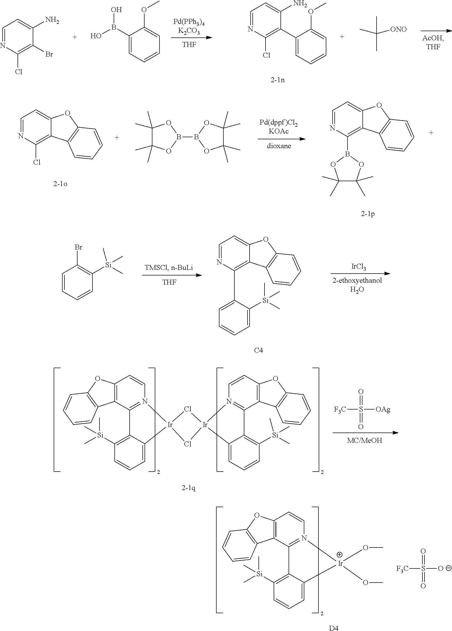


| TABLE 1 | |||||||
| Voltage | Efficiency | Color | Lifetime | ||||
| Dopant | max | (V) | (cd/A) | coordinate | (T95, h) | ||
| material | (nm) | (@10 mA/cm2) | (@10 mA/cm2) | (x, y) | (@50 mA/cm2) | ||
| | Compound | 1 | 526 | 3.32 | 68 | (0.340, 0.602) | 112 |
| Example 1 | |||||||
| | Compound | 2 | 530 | 3.13 | 76 | (0.362, 0.568) | 252 |
| Example 2 | |||||||
| | Compound | 3 | 528 | 3.20 | 70 | (0.358, 0.620) | 160 |
| Example 3 | |||||||
| | Compound | 4 | 526 | 3.25 | 74 | (0.336, 0.614) | 210 |
| Example 4 | |||||||
| | Compound | 5 | 527 | 3.18 | 76 | (0.385, 0.608) | 248 |
| Example 5 | |||||||
| | Compound | 7 | 528 | 3.21 | 78 | (0.379, 0.598) | 260 |
| Example 6 | |||||||
| Experimental | Compound 12 | 528 | 3.20 | 81 | (0.362, 0.611) | 278 | |
| Example 7 | |||||||
| Experimental | Compound 17 | 536 | 3.39 | 74 | (0.412, 0.576) | 241 | |
| Example 8 | |||||||
| Comparative | E1 | 560 | 3.51 | 67 | (0.448, 0.550) | 130 | |
| Experimental | |||||||
| Example 1 | |||||||
| Comparative | E2 | 532 | 3.30 | 70 | (0.402, 0.588) | 78 | |
| Experimental | |||||||
| Example 2 | |||||||
| Explanation of Symbols |
| 1: substrate | 2: anode | ||
| 3: light emitting layer | 4: cathode | ||
| 5: hole injection layer | 6: hole transport layer | ||
| 7: light emitting layer | 8: electron transport layer | ||
| 9: electron blocking layer | 10: electron injection layer | ||
Claims (14)


Applications Claiming Priority (3)
| Application Number | Priority Date | Filing Date | Title |
|---|---|---|---|
| KR1020170158934A KR102147480B1 (en) | 2017-11-24 | 2017-11-24 | Novel compound and organic light emitting device comprising the same |
| KR10-2017-0158934 | 2017-11-24 | ||
| PCT/KR2018/014215 WO2019103423A1 (en) | 2017-11-24 | 2018-11-19 | Novel compound and organic light emitting element using same |
Publications (2)
| Publication Number | Publication Date |
|---|---|
| US20200313098A1 US20200313098A1 (en) | 2020-10-01 |
| US11404654B2 true US11404654B2 (en) | 2022-08-02 |
Family
ID=66632102
Family Applications (1)
| Application Number | Title | Priority Date | Filing Date |
|---|---|---|---|
| US16/650,274 Active 2039-09-13 US11404654B2 (en) | 2017-11-24 | 2018-11-19 | Compound containing iridium complex with aza dibenzo group and organic light emitting device comprising same |
Country Status (5)
| Country | Link |
|---|---|
| US (1) | US11404654B2 (en) |
| JP (2) | JP7069506B2 (en) |
| KR (1) | KR102147480B1 (en) |
| CN (1) | CN111132986B (en) |
| WO (1) | WO2019103423A1 (en) |
Families Citing this family (6)
| Publication number | Priority date | Publication date | Assignee | Title |
|---|---|---|---|---|
| CN109988193B (en) * | 2019-01-16 | 2021-11-16 | 浙江华显光电科技有限公司 | Green phosphorescent compound and organic electroluminescent device using the same |
| CN111116674A (en) * | 2019-12-27 | 2020-05-08 | 吉林奥来德光电材料股份有限公司 | Iridium metal complex luminescent material and preparation method and application thereof |
| US12324348B2 (en) * | 2020-02-28 | 2025-06-03 | Universal Display Corporation | Organic electroluminescent materials and devices |
| KR20220087116A (en) * | 2020-12-17 | 2022-06-24 | 엘지디스플레이 주식회사 | Organometallic compound, organic light emitting diode and organic light emitting device including the organometallic compound |
| EP4039691A1 (en) * | 2021-02-05 | 2022-08-10 | Samsung Electronics Co., Ltd. | Organometallic compound, organic light-emitting device including the same, and electronic apparatus including the organic light-emitting device |
| KR20240104982A (en) * | 2022-12-28 | 2024-07-05 | 삼성전자주식회사 | Organic light emitting device and electronic apparatus comprising the same |
Citations (13)
| Publication number | Priority date | Publication date | Assignee | Title |
|---|---|---|---|---|
| KR20000051826A (en) | 1999-01-27 | 2000-08-16 | 성재갑 | New organomattalic complex molecule for the fabrication of organic light emitting diodes |
| WO2003012890A2 (en) | 2001-07-20 | 2003-02-13 | Novaled Gmbh | Light emitting component with organic layers |
| JP2005327526A (en) | 2004-05-13 | 2005-11-24 | Fuji Photo Film Co Ltd | Organic electroluminescence device |
| WO2010118029A1 (en) | 2009-04-06 | 2010-10-14 | Universal Display Corporation | Metal complex comprising novel ligand structures |
| US20130026452A1 (en) | 2011-07-28 | 2013-01-31 | Universal Display Corporation | Heteroleptic iridium complexes as dopants |
| KR20130110934A (en) | 2012-03-30 | 2013-10-10 | 에스에프씨 주식회사 | Organometallic compounds and organic light emitting diodes comprising the compounds |
| US8946697B1 (en) * | 2012-11-09 | 2015-02-03 | Universal Display Corporation | Iridium complexes with aza-benzo fused ligands |
| KR20150096520A (en) | 2012-12-21 | 2015-08-24 | 메르크 파텐트 게엠베하 | Metal complexes |
| US20160049597A1 (en) * | 2014-08-07 | 2016-02-18 | Universal Display Corporation | Organic electroluminescent materials and devices |
| EP3026056A1 (en) | 2014-11-28 | 2016-06-01 | Samsung Electronics Co., Ltd. | Organometallic compound and organic light-emitting device including the same |
| KR20160064955A (en) | 2014-11-28 | 2016-06-08 | 삼성전자주식회사 | Organometallic compound and organic light emitting device including the same |
| US20160268519A1 (en) | 2015-03-13 | 2016-09-15 | Samsung Electronics Co., Ltd. | Organometallic compound and organic light-emitting device including the same |
| KR20160136211A (en) | 2015-05-19 | 2016-11-29 | 롬엔드하스전자재료코리아유한회사 | Phosphorous Host Material and Organic Electroluminescent Device Comprising the Same |
-
2017
- 2017-11-24 KR KR1020170158934A patent/KR102147480B1/en active Active
-
2018
- 2018-11-19 CN CN201880060249.8A patent/CN111132986B/en active Active
- 2018-11-19 JP JP2020516419A patent/JP7069506B2/en active Active
- 2018-11-19 WO PCT/KR2018/014215 patent/WO2019103423A1/en not_active Ceased
- 2018-11-19 US US16/650,274 patent/US11404654B2/en active Active
-
2022
- 2022-03-01 JP JP2022031350A patent/JP2022078175A/en not_active Abandoned
Patent Citations (23)
| Publication number | Priority date | Publication date | Assignee | Title |
|---|---|---|---|---|
| KR20000051826A (en) | 1999-01-27 | 2000-08-16 | 성재갑 | New organomattalic complex molecule for the fabrication of organic light emitting diodes |
| WO2003012890A2 (en) | 2001-07-20 | 2003-02-13 | Novaled Gmbh | Light emitting component with organic layers |
| US20040251816A1 (en) | 2001-07-20 | 2004-12-16 | Karl Leo | Light emitting component with organic layers |
| JP2005327526A (en) | 2004-05-13 | 2005-11-24 | Fuji Photo Film Co Ltd | Organic electroluminescence device |
| KR101726459B1 (en) | 2009-04-06 | 2017-04-12 | 유니버셜 디스플레이 코포레이션 | Metal complex comprising novel ligand structures |
| WO2010118029A1 (en) | 2009-04-06 | 2010-10-14 | Universal Display Corporation | Metal complex comprising novel ligand structures |
| US20120061654A1 (en) | 2009-04-06 | 2012-03-15 | Universal Display Corporation | Metal complex comprising novel ligand structures |
| KR20120026486A (en) | 2009-04-06 | 2012-03-19 | 유니버셜 디스플레이 코포레이션 | Metal complex comprising novel ligand structures |
| JP2012522844A (en) | 2009-04-06 | 2012-09-27 | ユニバーサル ディスプレイ コーポレイション | Metal complexes containing novel ligand structures |
| US20130026452A1 (en) | 2011-07-28 | 2013-01-31 | Universal Display Corporation | Heteroleptic iridium complexes as dopants |
| KR20130018550A (en) | 2011-07-28 | 2013-02-25 | 유니버셜 디스플레이 코포레이션 | Heteroleptic iridium complexes as dopants |
| KR20130110934A (en) | 2012-03-30 | 2013-10-10 | 에스에프씨 주식회사 | Organometallic compounds and organic light emitting diodes comprising the compounds |
| US8946697B1 (en) * | 2012-11-09 | 2015-02-03 | Universal Display Corporation | Iridium complexes with aza-benzo fused ligands |
| KR20150096520A (en) | 2012-12-21 | 2015-08-24 | 메르크 파텐트 게엠베하 | Metal complexes |
| US20150318498A1 (en) | 2012-12-21 | 2015-11-05 | Merck Patent Gmbh | Metal Complexes |
| US20160049597A1 (en) * | 2014-08-07 | 2016-02-18 | Universal Display Corporation | Organic electroluminescent materials and devices |
| EP3026056A1 (en) | 2014-11-28 | 2016-06-01 | Samsung Electronics Co., Ltd. | Organometallic compound and organic light-emitting device including the same |
| US20160155962A1 (en) | 2014-11-28 | 2016-06-02 | Samsung Electronics Co., Ltd. | Organometallic compound and organic light-emitting device including the same |
| KR20160064955A (en) | 2014-11-28 | 2016-06-08 | 삼성전자주식회사 | Organometallic compound and organic light emitting device including the same |
| US20160268519A1 (en) | 2015-03-13 | 2016-09-15 | Samsung Electronics Co., Ltd. | Organometallic compound and organic light-emitting device including the same |
| KR20160109909A (en) | 2015-03-13 | 2016-09-21 | 삼성전자주식회사 | Organometallic compound and organic light emitting device including the same |
| KR20160136211A (en) | 2015-05-19 | 2016-11-29 | 롬엔드하스전자재료코리아유한회사 | Phosphorous Host Material and Organic Electroluminescent Device Comprising the Same |
| US20180105740A1 (en) | 2015-05-19 | 2018-04-19 | Rohm And Haas Electronic Materials Korea Ltd. | Phosphorous host material and organic electroluminescent device comprising the same |
Also Published As
| Publication number | Publication date |
|---|---|
| US20200313098A1 (en) | 2020-10-01 |
| WO2019103423A1 (en) | 2019-05-31 |
| CN111132986A (en) | 2020-05-08 |
| JP7069506B2 (en) | 2022-05-18 |
| KR20190060589A (en) | 2019-06-03 |
| CN111132986B (en) | 2023-01-06 |
| JP2022078175A (en) | 2022-05-24 |
| JP2020534304A (en) | 2020-11-26 |
| KR102147480B1 (en) | 2020-08-24 |
Similar Documents
| Publication | Publication Date | Title |
|---|---|---|
| US12098156B2 (en) | Compound and organic light emitting device comprising the same | |
| US12325713B2 (en) | Compound and organic light emitting device comprising the same | |
| US12060372B2 (en) | Compound and organic light emitting device comprising the same | |
| US11518769B2 (en) | Heterocyclic compounds and organic light emitting device using the same | |
| US11997925B2 (en) | Cyclic compound and organic light emitting device comprising same | |
| US11621397B2 (en) | Iridium complexes containing a ligand including a (dibenzo [B,D] furanyl) pyridine skeleton having deuterium substitutions para and meta to the N ring atom and organic light emitting device comprising the same | |
| US20180354913A1 (en) | Novel heterocyclic compound and organic light emitting device comprising the same | |
| US11370782B2 (en) | Compound and organic light emitting device comprising the same | |
| US11404654B2 (en) | Compound containing iridium complex with aza dibenzo group and organic light emitting device comprising same | |
| US11557736B2 (en) | Organometallic compound containing an iridium complex containing a 2-phenylpyridine ligand and an organic light emitting device comprising same | |
| US12058931B2 (en) | Heterocyclic compound and organic light emitting device comprising same | |
| US11807632B2 (en) | Heterocyclic compound and organic light emitting device comprising the same | |
| US11851423B2 (en) | Heterocyclic compound and organic light emitting device comprising the same | |
| US11925113B2 (en) | Heterocyclic compound and organic light emitting device comprising the same | |
| US20190352270A1 (en) | Novel heterocyclic compounds and organic light emitting device using the same | |
| US12010912B2 (en) | Heterocyclic compound and organic light emitting device comprising the same | |
| US11795161B2 (en) | Compound and organic light emitting device comprising same | |
| US20250127043A1 (en) | Novel compound and organic light emitting device comprising the same | |
| US12022730B2 (en) | Compound and organic light emitting device comprising the same | |
| US11778909B2 (en) | Compound and organic light emitting device comprising the same | |
| US11832517B2 (en) | Heterocyclic compound and organic light emitting device comprising same | |
| US12202838B2 (en) | Heterocyclic compound and organic light emitting device comprising same | |
| US12507589B2 (en) | Organic light emitting device | |
| US12391678B2 (en) | Compound and organic light emitting device comprising same | |
| US20240324269A1 (en) | Novel compound and organic light emitting device comprising the same |
Legal Events
| Date | Code | Title | Description |
|---|---|---|---|
| AS | Assignment |
Owner name: LG CHEM, LTD., KOREA, REPUBLIC OF Free format text: ASSIGNMENT OF ASSIGNORS INTEREST;ASSIGNORS:KIM, SEOYEON;PARK, TAE YOON;JEON, SANG YOUNG;AND OTHERS;REEL/FRAME:052214/0819 Effective date: 20200205 |
|
| FEPP | Fee payment procedure |
Free format text: ENTITY STATUS SET TO UNDISCOUNTED (ORIGINAL EVENT CODE: BIG.); ENTITY STATUS OF PATENT OWNER: LARGE ENTITY |
|
| STPP | Information on status: patent application and granting procedure in general |
Free format text: APPLICATION DISPATCHED FROM PREEXAM, NOT YET DOCKETED |
|
| STPP | Information on status: patent application and granting procedure in general |
Free format text: DOCKETED NEW CASE - READY FOR EXAMINATION |
|
| STPP | Information on status: patent application and granting procedure in general |
Free format text: NON FINAL ACTION MAILED |
|
| STPP | Information on status: patent application and granting procedure in general |
Free format text: RESPONSE TO NON-FINAL OFFICE ACTION ENTERED AND FORWARDED TO EXAMINER |
|
| STPP | Information on status: patent application and granting procedure in general |
Free format text: PUBLICATIONS -- ISSUE FEE PAYMENT VERIFIED |
|
| STCF | Information on status: patent grant |
Free format text: PATENTED CASE |
|
| MAFP | Maintenance fee payment |
Free format text: PAYMENT OF MAINTENANCE FEE, 4TH YEAR, LARGE ENTITY (ORIGINAL EVENT CODE: M1551); ENTITY STATUS OF PATENT OWNER: LARGE ENTITY Year of fee payment: 4 |