US11403441B2 - Method for checking a vehicle dynamics model - Google Patents
Method for checking a vehicle dynamics model Download PDFInfo
- Publication number
- US11403441B2 US11403441B2 US16/925,662 US202016925662A US11403441B2 US 11403441 B2 US11403441 B2 US 11403441B2 US 202016925662 A US202016925662 A US 202016925662A US 11403441 B2 US11403441 B2 US 11403441B2
- Authority
- US
- United States
- Prior art keywords
- vehicle
- values
- dynamics model
- variable
- vehicle dynamics
- Prior art date
- Legal status (The legal status is an assumption and is not a legal conclusion. Google has not performed a legal analysis and makes no representation as to the accuracy of the status listed.)
- Active, expires
Links
Images


Classifications
-
- G—PHYSICS
- G01—MEASURING; TESTING
- G01M—TESTING STATIC OR DYNAMIC BALANCE OF MACHINES OR STRUCTURES; TESTING OF STRUCTURES OR APPARATUS, NOT OTHERWISE PROVIDED FOR
- G01M17/00—Testing of vehicles
- G01M17/007—Wheeled or endless-tracked vehicles
-
- B—PERFORMING OPERATIONS; TRANSPORTING
- B60—VEHICLES IN GENERAL
- B60W—CONJOINT CONTROL OF VEHICLE SUB-UNITS OF DIFFERENT TYPE OR DIFFERENT FUNCTION; CONTROL SYSTEMS SPECIALLY ADAPTED FOR HYBRID VEHICLES; ROAD VEHICLE DRIVE CONTROL SYSTEMS FOR PURPOSES NOT RELATED TO THE CONTROL OF A PARTICULAR SUB-UNIT
- B60W50/00—Details of control systems for road vehicle drive control not related to the control of a particular sub-unit, e.g. process diagnostic or vehicle driver interfaces
- B60W50/0098—Details of control systems ensuring comfort, safety or stability not otherwise provided for
-
- G—PHYSICS
- G06—COMPUTING; CALCULATING OR COUNTING
- G06F—ELECTRIC DIGITAL DATA PROCESSING
- G06F30/00—Computer-aided design [CAD]
- G06F30/20—Design optimisation, verification or simulation
-
- G—PHYSICS
- G06—COMPUTING; CALCULATING OR COUNTING
- G06F—ELECTRIC DIGITAL DATA PROCESSING
- G06F17/00—Digital computing or data processing equipment or methods, specially adapted for specific functions
- G06F17/10—Complex mathematical operations
- G06F17/11—Complex mathematical operations for solving equations, e.g. nonlinear equations, general mathematical optimization problems
- G06F17/13—Differential equations
-
- G—PHYSICS
- G06—COMPUTING; CALCULATING OR COUNTING
- G06F—ELECTRIC DIGITAL DATA PROCESSING
- G06F17/00—Digital computing or data processing equipment or methods, specially adapted for specific functions
- G06F17/10—Complex mathematical operations
- G06F17/18—Complex mathematical operations for evaluating statistical data, e.g. average values, frequency distributions, probability functions, regression analysis
-
- G—PHYSICS
- G06—COMPUTING; CALCULATING OR COUNTING
- G06F—ELECTRIC DIGITAL DATA PROCESSING
- G06F30/00—Computer-aided design [CAD]
- G06F30/10—Geometric CAD
- G06F30/15—Vehicle, aircraft or watercraft design
-
- G06N7/005—
-
- G—PHYSICS
- G06—COMPUTING; CALCULATING OR COUNTING
- G06N—COMPUTING ARRANGEMENTS BASED ON SPECIFIC COMPUTATIONAL MODELS
- G06N7/00—Computing arrangements based on specific mathematical models
- G06N7/01—Probabilistic graphical models, e.g. probabilistic networks
-
- B—PERFORMING OPERATIONS; TRANSPORTING
- B60—VEHICLES IN GENERAL
- B60W—CONJOINT CONTROL OF VEHICLE SUB-UNITS OF DIFFERENT TYPE OR DIFFERENT FUNCTION; CONTROL SYSTEMS SPECIALLY ADAPTED FOR HYBRID VEHICLES; ROAD VEHICLE DRIVE CONTROL SYSTEMS FOR PURPOSES NOT RELATED TO THE CONTROL OF A PARTICULAR SUB-UNIT
- B60W50/00—Details of control systems for road vehicle drive control not related to the control of a particular sub-unit, e.g. process diagnostic or vehicle driver interfaces
- B60W2050/0001—Details of the control system
- B60W2050/0019—Control system elements or transfer functions
- B60W2050/0028—Mathematical models, e.g. for simulation
- B60W2050/0031—Mathematical model of the vehicle
-
- B—PERFORMING OPERATIONS; TRANSPORTING
- B60—VEHICLES IN GENERAL
- B60W—CONJOINT CONTROL OF VEHICLE SUB-UNITS OF DIFFERENT TYPE OR DIFFERENT FUNCTION; CONTROL SYSTEMS SPECIALLY ADAPTED FOR HYBRID VEHICLES; ROAD VEHICLE DRIVE CONTROL SYSTEMS FOR PURPOSES NOT RELATED TO THE CONTROL OF A PARTICULAR SUB-UNIT
- B60W50/00—Details of control systems for road vehicle drive control not related to the control of a particular sub-unit, e.g. process diagnostic or vehicle driver interfaces
- B60W2050/0062—Adapting control system settings
- B60W2050/0075—Automatic parameter input, automatic initialising or calibrating means
- B60W2050/0083—Setting, resetting, calibration
- B60W2050/0088—Adaptive recalibration
Definitions
- the present invention relates to a method for checking a vehicle dynamics model of a vehicle, with which a value of an output variable is ascertainable from a value of a variable input variable, as well as a processing unit and a computer program for its implementation.
- Vehicle dynamics models play a role, in particular, in the area of driver assistance systems, increasingly and generally, however, also in the area of autonomous or automated driving of vehicles, in particular, passenger vehicles or also trucks.
- a vehicle dynamics model is a model of a vehicle, with which dynamic situations of the vehicle operation may be represented or modeled in such a way that a value of an output variable is ascertainable from a value of a variable input variable.
- One example of this would be to ascertain for a particular value of a steering angle a resulting value of a yaw rate. In this way, it is possible to predict the behavior of the vehicle at least for a certain time period.
- a method for checking a vehicle dynamics model as well as a processing unit and a computer program for its implementation are provided including the features of the independent patent claims.
- Advantageous embodiments of the present invention are described herein.
- the present invention relates to a method for checking a vehicle dynamics model of a vehicle, with which a value of at least one output variable is ascertainable from a value of at least one variable input variable. It is understood that from values of one or of multiple input variables, corresponding values of one or of multiple output variables may be ascertained, depending on the type of vehicle dynamics model.
- Such models may further preferably be used for predictions.
- Such a dynamic model may, for example, be used during autonomous driving, when multiple trajectories (potential paths) during an evasive maneuver are calculated and compared. In this case, a prediction is made for only a short time horizon, of how the vehicle behaves when various options are selected. Another case involves, for example, planning an energetically optimal negotiation of curves.
- Such vehicle dynamics models are also relevant for vehicle assistance systems, in particular however also in the area of autonomous or automated driving. As has been demonstrated, an important point here is also that such a vehicle dynamics model also sufficiently accurately models or represents the actual behavior of the vehicle in a continuous manner. Otherwise, potentially different functions of the vehicle may no longer be represented or ensured—in particular, taking safety aspects into account.
- the actual conditions or the actual behavior of the vehicle may change over time, for example, due to wear of various components or the like. It is also possible, however, that under certain, only temporary existing conditions, a vehicle dynamics model does not sufficiently accurately model the vehicle. Modifications to the vehicle, in addition to wear, may also play a role, i.e., for example, the mounting of a roof box or of a bicycle rack or the like.
- a check of such a vehicle dynamics model is performed, and it is assessed whether the vehicle dynamics model may be considered to be valid, i.e., whether it sufficiently accurately models the actual behavior of the vehicle and, therefore, can or may be (instantaneously or furthermore) used.
- Difference values i.e., those each based respectively on the same value of the input variable, are then each ascertained from mutually corresponding model-based values and vehicle-based values, i.e., a difference is formed from a model-based and vehicle-based value.
- the difference values ascertained in this way then form an updated dataset.
- This updated dataset is then compared with a comparison dataset with the aid of a comparison method, a concordance measure being ascertained. If the concordance measure meets a predefined concordance criterion, the vehicle dynamics model is determined to be valid. Otherwise, the vehicle dynamics model is appropriately determined to be invalid.
- One particular advantage of the example method provided is that it may be carried out in real time or during the drive, i.e., the difference values related to the multiple values of the input variable are ascertained preferably during an operation of the vehicle. In this way, it is possible to continuously check whether or not a particular vehicle dynamics model—the method provided may also be carried out for multiple different vehicle dynamics models used in a vehicle—can or may be instantaneously used.
- the comparison dataset used may preferably be a dataset, which has been obtained in the same manner as the updated dataset, but, for example, within the scope of test measurements or during an initial operation of the vehicle or also only in another comparison period, in which it is assumed or is known that the vehicle dynamics model sufficiently accurately models the actual method.
- the difference values relating to the multiple values of the input variable are ascertained in temporal succession, in particular, at predetermined time intervals.
- the updated data set may also always be kept updated. It is particularly advantageous—and also advantageous for limiting a necessary processing power—if the updated dataset is determined only from a predetermined number of difference values, i.e., from a particular number of the difference values most recently ascertained.
- the multiple values of the input variable result, in particular, due to the actual behavior or operation of the vehicle and may therefore also be repeated.
- the values for example, do not—or they at least should not, change when driving straight ahead.
- the comparison of the updated dataset with the comparison dataset in this case may take place in such a way that both the updated dataset as well as the comparison dataset—each of which includes a particular number of difference values—may be used as a histogram or probability distribution or frequency distribution or may be converted into such or may be represented as such. There are suitable comparison methods for such purpose.
- the comparison method is preferably a histogram difference, in particular, the so-called Jensen-Shannon divergence, or a use of such a histogram difference.
- the histogram difference is a positive number resulting from the formation of the difference between two histograms. It is used as a measure of the difference between two histograms and may be correspondingly also used as a measure of the concordance—i.e., a concordance measure—or a concordance measure may be ascertained therefrom.
- the Jensen-Shannon divergence in particular, represents a variant or modification of the so-called Kullback-Leibler divergence and will be explained in greater detail in conjunction with the figure description.
- the vehicle dynamics model is preferably determined to be invalid if the concordance measure does not meet the predefined concordance criterion.
- An error response may be initiated, in particular, in the case of a model determined to be invalid.
- Such an error response may, for example, encompass initiating a safety response, for example, by a limited operating mode, for a particular vehicle function, for example, for a driver assistance function or for another function for which the vehicle dynamics model is used.
- Conceivable as an error response is, however, also an error memory entry, a warning to the driver of the vehicle (for example, as an alert in a display means), or a switch over into another driver assistance function or the like. It is understood that such an error response may be selected depending on the type of the vehicle dynamics model and/or of its use. Multiple of the aforementioned and/or other error responses may also be initiated.
- the safety of a vehicle is enhanced overall with the method provided, in particular, including driver assistance systems and especially particularly during autonomous or automated driving.
- a processing unit for example, a control unit of a motor vehicle is configured, in particular, programmed, to carry out a method according to the present invention.
- Suitable data media for providing the computer program are, in particular, magnetic, optical or electrical memories such as, for example, hard disks, flash memories, EEPROMs, DVDs among others.
- a download of a program via computer networks Internet, Intranet, etc. is also possible.
- FIG. 1 schematically shows a vehicle, in which an example method according to the present invention is implementable.
- FIG. 2 schematically shows a sequence of an example method according to the present invention in one preferred specific embodiment.
- FIGS. 3 through 5 show diagrams for explaining the example method shown in FIG. 2 .
- FIG. 1 schematically depicts a vehicle 100 , in which a method according to the present invention is implementable.
- a processing unit 150 on which, for example, a driver assistance system may be operated, which takes a yaw rate into consideration, is provided, for example, in vehicle 100 .
- a yaw rate sensor 155 is also provided, with the aid of which a yaw rate may be ascertained and conveyed to processing unit 150 .
- a steering wheel 140 is also indicated, with the aid of which a steering angle may be set. The steering angle may be detected, for example, with the aid of steering angle sensor 145 and conveyed to processing unit 150 . It is understood that a steering angle may be set or changed also in an automated manner in conjunction with a driver assistance function and/or in conjunction with autonomous or automated driving.
- FIG. 2 schematically depicts a sequence of a method according to the present invention in one specific embodiment. This method may, for example be carried out on processing unit 150 , as it is shown in FIG. 1 .
- FIGS. 3 through 5 show diagrams for explaining the method shown in FIG. 2 .
- values W E are each detected or ascertained repeatedly or in temporal succession for one or for multiple input variables E.
- the input variable may, for example, be a steering angle which, or the values of which, may be ascertained as explained with reference to FIG. 1 .
- the output variable A may, for example, be a yaw rate which, or the values of which, may be ascertained or measured with the aid of the yaw rate sensor as explained with reference to FIG. 1 .
- a corresponding, model-based value W M of output variable A i.e., in this case a yaw rate, is ascertained or calculated in parallel thereto with the aid of a vehicle dynamics model M.
- Such a vehicle dynamics model with which a yaw rate ⁇ dot over ( ⁇ ) ⁇ may be ascertained based on a steering angle ⁇ , may be represented by the following differential equations:
- [ ⁇ ⁇ ⁇ . ] [ - 1 v ⁇ c f ⁇ l v 2 + c r ⁇ l r 2 ⁇ - c f ⁇ l f + c r ⁇ l r ⁇ - 1 - 1 v 2 ⁇ c f ⁇ l f + c r ⁇ l r m - 1 v ⁇ c f + c r m ] ⁇ [ ⁇ . ⁇ ] + [ c f + c f ⁇ 1 v ⁇ c f m ] ⁇ ⁇ i
- ß indicates a lateral slip angle
- ⁇ indicates the steering angle
- i indicates the ratio between the steering angle (or steering wheel angle) and the wheel angle
- v indicates the vehicle velocity
- ⁇ indicates the yaw inertia
- c f and c r indicate the front and rear lateral stability of the tires
- l f and l r indicate the front and rear distance between the wheel and center of gravity
- m indicates the vehicle mass.
- the wheel angle in this case is thus determined as a quotient of the ratio i and the steering angle ⁇ .
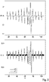
- an exemplary profile of a steering angle is depicted in the upper diagram in FIG. 3 as input variable E over time t in seconds.
- a corresponding profile V 1 for the actual or measured profile of the yaw rate as output variable A, as well as a profile V 2 for the profile of the yaw rate ascertained with the aid of the vehicle dynamics model, are depicted in the lower diagram.
- the values W F and W M may be ascertained repeatedly, for example, at an interval of one second or 100 ms, respectively.
- a difference value W D is also ascertained or formed from respectively one pair of mutually corresponding values W F and W M .
- This difference value W D is then fed to a buffer memory B, in which all difference values ascertained in this way (in temporal succession) are stored.
- An updated dataset H A is then formed from these difference values W D present in buffer memory B.
- a particular number for example, 300, the most updated or the latest difference values ascertained and stored in the buffer memory may be used, for example.
- This updated dataset H A is then processed in the form of a histogram, i.e., of a frequency distribution.
- This updated dataset may then be compared in conjunction with a comparison method or a comparison step 210 with a comparison dataset or reference dataset H R — also depicted in the form of a histogram.
- a concordance measure ⁇ H is ascertained and then compared with a predefined threshold value ⁇ H s .
- FIG. 4 depicts a comparison dataset H R on the left and an updated dataset H A on the right, each in the form of a histogram.
- a number N of difference values is plotted over a value of difference values W D in 10 ⁇ 2 in each case.
- the two histograms must, if necessary, still be standardized.
- the comparison method is explained briefly and by way of example below with reference to the previously mentioned Jensen-Shannon divergence.
- This divergence is based on the so-called Kullback-Leibler divergence.
- the Kullback-Leibler divergence measures to what degree a probability distribution P(x) differs from a second probability distribution Q(x).
- the Kullback-Leibler divergence D KL for discrete probability distributions in the same probability space is defined in this case as follows:
- the infinite values of the Kullback-Leibler divergence result in problems in the practical implementation.
- D JS Jensen-Shannon divergence
- P ⁇ Q the so-called Jensen-Shannon divergence
- H A and comparison dataset H R which represent the histograms or frequency distributions P and Q in the above notation, is a concordance measure (or divergence measure) ⁇ H, in the case of the Jensen-Shannon divergence, a positive number.
- FIG. 5 shows a profile of such a concordance measure (or divergence measure) ⁇ H over time t in seconds, as results for the profiles of the output variables in the lower diagram of FIG. 3 .
- the concordance measure ⁇ H increases sharply, in particular in the area of the unusual and sharp steering angle changes between the points in time 70 and 80 seconds.
- a value of 0.25 may be selected as threshold value ⁇ H s , the vehicle dynamics model being determined to be valid if the concordance measure is below the threshold value, i.e., if: ⁇ H ⁇ H s applies.
- an error response may then be initiated if the vehicle dynamics model is not determined to be valid or is determined to be invalid, as previously explained in detail above. If, however, the vehicle dynamics model is determined to be valid, it may be used as usual for desired functions.
- the vehicle dynamics model is determined to be only temporarily invalid and is then not used during this time period. Later, however, it may then be used again, for example.
Abstract
Description
D KL2(P∥Q)=D KL2(Q∥P)=D KL(P∥Q)+D KL(P∥Q)
is often applied in order to ensure the symmetry. However, the infinite values of the Kullback-Leibler divergence result in problems in the practical implementation. For this reason, the so-called Jensen-Shannon divergence DJS is preferred, which is symmetrical and limited and is based on the Kullback-Leibler divergence as follows:
D JS(P∥Q)=½D KL(P∥M)+½D KL(Q∥M)
where M=0.5·(P+Q) applies. The result of a comparison of updated dataset HA and comparison dataset HR, which represent the histograms or frequency distributions P and Q in the above notation, is a concordance measure (or divergence measure) ΔH, in the case of the Jensen-Shannon divergence, a positive number.
Claims (9)
Applications Claiming Priority (2)
| Application Number | Priority Date | Filing Date | Title |
|---|---|---|---|
| DE102019211951.4A DE102019211951A1 (en) | 2019-08-08 | 2019-08-08 | Method for checking a vehicle dynamics model |
| DE102019211951.4 | 2019-08-08 |
Publications (2)
| Publication Number | Publication Date |
|---|---|
| US20210042451A1 US20210042451A1 (en) | 2021-02-11 |
| US11403441B2 true US11403441B2 (en) | 2022-08-02 |
Family
ID=74188296
Family Applications (1)
| Application Number | Title | Priority Date | Filing Date |
|---|---|---|---|
| US16/925,662 Active 2040-12-07 US11403441B2 (en) | 2019-08-08 | 2020-07-10 | Method for checking a vehicle dynamics model |
Country Status (3)
| Country | Link |
|---|---|
| US (1) | US11403441B2 (en) |
| CN (1) | CN112345264A (en) |
| DE (1) | DE102019211951A1 (en) |
Citations (2)
| Publication number | Priority date | Publication date | Assignee | Title |
|---|---|---|---|---|
| US20100318336A1 (en) * | 2009-06-13 | 2010-12-16 | Falangas Eric T | Method of modeling dynamic characteristics of a flight vehicle |
| US20190318051A1 (en) * | 2016-07-13 | 2019-10-17 | Avl List Gmbh | Method for simulation-based analysis of a motor vehicle |
-
2019
- 2019-08-08 DE DE102019211951.4A patent/DE102019211951A1/en active Pending
-
2020
- 2020-07-10 US US16/925,662 patent/US11403441B2/en active Active
- 2020-08-07 CN CN202010789051.2A patent/CN112345264A/en active Pending
Patent Citations (2)
| Publication number | Priority date | Publication date | Assignee | Title |
|---|---|---|---|---|
| US20100318336A1 (en) * | 2009-06-13 | 2010-12-16 | Falangas Eric T | Method of modeling dynamic characteristics of a flight vehicle |
| US20190318051A1 (en) * | 2016-07-13 | 2019-10-17 | Avl List Gmbh | Method for simulation-based analysis of a motor vehicle |
Non-Patent Citations (6)
| Title |
|---|
| Albert Lutz, Bernhard Schick, Henning Holzmann, Michael Kochem, Harald Meyer-Tuve, Olav Lange, Yiqin Mao & Guido Tosolin (2017) Simulation methods supporting homologation of Electronic Stability Control in vehicle variants, Vehicle System Dynamics, (Year: 2017). * |
| Ao D, Hu Z, Mahadevan S. Dynamics model validation using time-domain metrics. Journal of Verification, Validation and Uncertainty Quantification. Mar. 1, 2017 ;2(1). (Year: 2017). * |
| Jo K, Chu K, Sunwoo M. Interacting multiple model filter-based sensor fusion of GPS with in-vehicle sensors for real-time vehicle positioning. IEEE Transactions on Intelligent Transportation Systems. Dec. 6, 2011;13(1):329-43. (Year: 2011). * |
| Maupin KA, Swiler LP, Porter NW. Validation metrics for deterministic and probabilistic data. Sandia Report (Year: 2017). * |
| Rhode S, Gauterin F. Online estimation of vehicle driving resistance parameters with recursive least squares and recursive total least squares. In2013 IEEE Intelligent Vehicles Symposium (IV) Jun. 23, 2013 (pp. 269-276). IEEE. (Year: 2013). * |
| Rhode S, Von Keler J. Online validity monitor for vehicle dynamics models. In2019 IEEE International Conference on Connected Vehicles and Expo (ICCVE) Nov. 4, 2019 (pp. 1-6). IEEE. (Year: 2019). * |
Also Published As
| Publication number | Publication date |
|---|---|
| US20210042451A1 (en) | 2021-02-11 |
| CN112345264A (en) | 2021-02-09 |
| DE102019211951A1 (en) | 2021-02-11 |
Similar Documents
| Publication | Publication Date | Title |
|---|---|---|
| US10370004B2 (en) | System and method for determining state of stiffness of tires of vehicle | |
| US8340883B2 (en) | Method and apparatus for predicting a movement trajectory | |
| JP4140720B2 (en) | Vehicle behavior reproduction system | |
| Kang et al. | Comparative evaluation of dynamic and kinematic vehicle models | |
| US6470300B1 (en) | Method and system for detecting and localizing sensor defects in motor vehicles | |
| US9771072B2 (en) | Vehicle control system and method for self-control driving thereof | |
| CN111868801B (en) | Route generation device and vehicle control system | |
| US8260501B2 (en) | Awake state estimation device | |
| EP3715204A1 (en) | Vehicle control device | |
| US20200148260A1 (en) | Lane changing system and lane changing method | |
| JP7371269B2 (en) | Method and device for calibrating camera pitch of a car, and method for continuously learning a vanishing point estimation model for the purpose | |
| WO2022072172A1 (en) | Systems and methods for imminent collision avoidance | |
| US20100100360A1 (en) | Model-based road surface condition identification | |
| US20220289181A1 (en) | Method for detecting driver's hands on/off steering wheel during driving and system thereof | |
| US10906537B2 (en) | System and method of determining risk situation of collision of autonomous vehicle | |
| US10255815B2 (en) | Method and control unit for monitoring the lane of a vehicle | |
| US9168926B2 (en) | Driving concentration level calculating apparatus and method, and system and method for warning of vehicle collision using the same | |
| US11403441B2 (en) | Method for checking a vehicle dynamics model | |
| CN114291071B (en) | Method and system for judging active intervention time of vehicle stability control, readable storage medium and vehicle | |
| EP2364891B1 (en) | Method for threat assessment in a vehicle | |
| CN115303288A (en) | Vehicle control method, control device and camera device | |
| US7689392B2 (en) | Method and apparatus for controlling a vehicle computer model | |
| CN114771555A (en) | Autonomous parking fault diagnosis method and device and unmanned vehicle | |
| KR20230023080A (en) | Power steering apparatus and method for autonomous vehicle | |
| EP3654246B1 (en) | Method, vehicle, system, and storage medium for indicating anomalous vehicle scenario using encoder network and replay buffer |
Legal Events
| Date | Code | Title | Description |
|---|---|---|---|
| FEPP | Fee payment procedure |
Free format text: ENTITY STATUS SET TO UNDISCOUNTED (ORIGINAL EVENT CODE: BIG.); ENTITY STATUS OF PATENT OWNER: LARGE ENTITY |
|
| STPP | Information on status: patent application and granting procedure in general |
Free format text: DOCKETED NEW CASE - READY FOR EXAMINATION |
|
| AS | Assignment |
Owner name: ROBERT BOSCH GMBH, GERMANY Free format text: ASSIGNMENT OF ASSIGNORS INTEREST;ASSIGNORS:RHODE, STEPHAN;VON KELER, JOHANNES;REEL/FRAME:055396/0181 Effective date: 20210224 |
|
| STPP | Information on status: patent application and granting procedure in general |
Free format text: NON FINAL ACTION MAILED |
|
| STPP | Information on status: patent application and granting procedure in general |
Free format text: RESPONSE TO NON-FINAL OFFICE ACTION ENTERED AND FORWARDED TO EXAMINER |
|
| STPP | Information on status: patent application and granting procedure in general |
Free format text: NOTICE OF ALLOWANCE MAILED -- APPLICATION RECEIVED IN OFFICE OF PUBLICATIONS |
|
| STCF | Information on status: patent grant |
Free format text: PATENTED CASE |