US11403245B2 - Terminal, terminal peripheral, signal transmission system and signal sending and receiving method - Google Patents
Terminal, terminal peripheral, signal transmission system and signal sending and receiving method Download PDFInfo
- Publication number
- US11403245B2 US11403245B2 US16/755,616 US201816755616A US11403245B2 US 11403245 B2 US11403245 B2 US 11403245B2 US 201816755616 A US201816755616 A US 201816755616A US 11403245 B2 US11403245 B2 US 11403245B2
- Authority
- US
- United States
- Prior art keywords
- terminal
- usb
- bus
- audio
- module
- Prior art date
- Legal status (The legal status is an assumption and is not a legal conclusion. Google has not performed a legal analysis and makes no representation as to the accuracy of the status listed.)
- Active
Links
Images


Classifications
-
- G—PHYSICS
- G06—COMPUTING OR CALCULATING; COUNTING
- G06F—ELECTRIC DIGITAL DATA PROCESSING
- G06F13/00—Interconnection of, or transfer of information or other signals between, memories, input/output devices or central processing units
- G06F13/38—Information transfer, e.g. on bus
- G06F13/382—Information transfer, e.g. on bus using universal interface adapter
- G06F13/385—Information transfer, e.g. on bus using universal interface adapter for adaptation of a particular data processing system to different peripheral devices
-
- G—PHYSICS
- G06—COMPUTING OR CALCULATING; COUNTING
- G06F—ELECTRIC DIGITAL DATA PROCESSING
- G06F13/00—Interconnection of, or transfer of information or other signals between, memories, input/output devices or central processing units
- G06F13/38—Information transfer, e.g. on bus
-
- H—ELECTRICITY
- H04—ELECTRIC COMMUNICATION TECHNIQUE
- H04R—LOUDSPEAKERS, MICROPHONES, GRAMOPHONE PICK-UPS OR LIKE ACOUSTIC ELECTROMECHANICAL TRANSDUCERS; ELECTRIC HEARING AIDS; PUBLIC ADDRESS SYSTEMS
- H04R3/00—Circuits for transducers
-
- G—PHYSICS
- G06—COMPUTING OR CALCULATING; COUNTING
- G06F—ELECTRIC DIGITAL DATA PROCESSING
- G06F2213/00—Indexing scheme relating to interconnection of, or transfer of information or other signals between, memories, input/output devices or central processing units
- G06F2213/0016—Inter-integrated circuit (I2C)
-
- G—PHYSICS
- G06—COMPUTING OR CALCULATING; COUNTING
- G06F—ELECTRIC DIGITAL DATA PROCESSING
- G06F2213/00—Indexing scheme relating to interconnection of, or transfer of information or other signals between, memories, input/output devices or central processing units
- G06F2213/0042—Universal serial bus [USB]
-
- G—PHYSICS
- G06—COMPUTING OR CALCULATING; COUNTING
- G06F—ELECTRIC DIGITAL DATA PROCESSING
- G06F2213/00—Indexing scheme relating to interconnection of, or transfer of information or other signals between, memories, input/output devices or central processing units
- G06F2213/38—Universal adapter
- G06F2213/3812—USB port controller
-
- H—ELECTRICITY
- H04—ELECTRIC COMMUNICATION TECHNIQUE
- H04R—LOUDSPEAKERS, MICROPHONES, GRAMOPHONE PICK-UPS OR LIKE ACOUSTIC ELECTROMECHANICAL TRANSDUCERS; ELECTRIC HEARING AIDS; PUBLIC ADDRESS SYSTEMS
- H04R1/00—Details of transducers, loudspeakers or microphones
- H04R1/10—Earpieces; Attachments therefor ; Earphones; Monophonic headphones
-
- H—ELECTRICITY
- H04—ELECTRIC COMMUNICATION TECHNIQUE
- H04R—LOUDSPEAKERS, MICROPHONES, GRAMOPHONE PICK-UPS OR LIKE ACOUSTIC ELECTROMECHANICAL TRANSDUCERS; ELECTRIC HEARING AIDS; PUBLIC ADDRESS SYSTEMS
- H04R2420/00—Details of connection covered by H04R, not provided for in its groups
- H04R2420/03—Connection circuits to selectively connect loudspeakers or headphones to amplifiers
-
- H—ELECTRICITY
- H04—ELECTRIC COMMUNICATION TECHNIQUE
- H04R—LOUDSPEAKERS, MICROPHONES, GRAMOPHONE PICK-UPS OR LIKE ACOUSTIC ELECTROMECHANICAL TRANSDUCERS; ELECTRIC HEARING AIDS; PUBLIC ADDRESS SYSTEMS
- H04R2420/00—Details of connection covered by H04R, not provided for in its groups
- H04R2420/09—Applications of special connectors, e.g. USB, XLR, in loudspeakers, microphones or headphones
-
- H—ELECTRICITY
- H04—ELECTRIC COMMUNICATION TECHNIQUE
- H04R—LOUDSPEAKERS, MICROPHONES, GRAMOPHONE PICK-UPS OR LIKE ACOUSTIC ELECTROMECHANICAL TRANSDUCERS; ELECTRIC HEARING AIDS; PUBLIC ADDRESS SYSTEMS
- H04R2460/00—Details of hearing devices, i.e. of ear- or headphones covered by H04R1/10 or H04R5/033 but not provided for in any of their subgroups, or of hearing aids covered by H04R25/00 but not provided for in any of its subgroups
- H04R2460/03—Aspects of the reduction of energy consumption in hearing devices
Definitions
- the present application relates to, but not limited to, the field of electronic devices, and in particular, to a terminal, a terminal peripheral, a signal transmission system, and a signal sending and receiving method.
- USB Universal Serial Bus
- signal interference, signal delay, and large power consumption often occur, for example, in an overall design of an earphone, large signal interference, call delay, and large overall power consumption often occur.
- UAC USB Audio Class
- FIG. 1 shows a structure of an analog-digital mixed USB Type-C earphone.
- USB Type-C interface When the USB Type-C interface is connected to an analog earphone adapter and then has an earphone plugged in, the earphone is still an analog earphone, the signals are still easily interfered when listening music and making a call, and High Fidelity (HIFI) performance of the earphone cannot be reliably guaranteed.
- USB-I2S USB-inter IC sound
- audio signals are transmitted by using an I2S over USB technology, and audio signal stream performs data transmission through a USB physical channel.
- a USB interface is usually hung on an application (AP) processor, and when the USB is working, the AP cannot sleep, thereby resulting in relatively large power consumption.
- a host and the earphone need to perform bridge conversion from I2S to USB and from USB to I2S, and additional power consumption is also relatively large.
- the addition of the AP and the conversion bridge will significantly reduce battery life time of a mobile terminal, and user experience may be deteriorated.
- USB enumeration delay exists in an analog and digital mode switching scenario, a user will perceive lags, and an overall experience effect of the user on the product will be reduced.
- Embodiments of the present application provide a terminal, a terminal peripheral, a signal transmission system and a signal sending and receiving method.
- a terminal includes a first audio module and a USB receptacle.
- the first audio module is connected to the USB receptacle in a terminal through an audio bus channel and is configured to send a signal to be sent to the USB receptacle.
- the USB receptacle is configured to provide a physical connection interface between the terminal and a terminal peripheral.
- a terminal peripheral includes a second audio module and USB plug.
- the second audio module is connected to a USB plug in a terminal peripheral through an audio bus channel and is configured to perform signal transmission with the USB plug through an I2S bus channel.
- the USB plug is configured to be connected to a USB receptacle of a terminal accessed by the terminal peripheral.
- a signal transmission system is further provided.
- the signal transmission system includes any one of the above terminals and any one of the above terminal peripherals.
- a signal sending method is further provided.
- the signal sending method includes a step described below.
- a terminal sends a signal to be sent to a USB receptacle in the terminal through a bus channel, and sends the signal to be sent to a terminal peripheral through the USB receptacle.
- a signal receiving method is further provided.
- the signal receiving method includes a step described below.
- a terminal peripheral receives a signal from a terminal through a USB plug of the terminal peripheral, and sends, through an audio bus channel, the signal to a second audio module in the terminal peripheral.
- FIG. 1 is a schematic diagram of a structure of an analog-digital mixed USB Type-C earphone in the related art
- FIG. 2 is a schematic system diagram of an I2S naked over USB Type-C interface according to an embodiment of the present application
- FIG. 3A is a schematic diagram illustrating establishment of an I2S channel and a USB channel when a peripheral is plugged in a forward direction according to an embodiment of the present application;
- FIG. 3B is a schematic diagram illustrating a correspondence between receptacle pins and plug pins when a peripheral is plugged in a forward direction according to an embodiment of the present application;
- FIG. 4A is a schematic diagram illustrating establishment of an I2S channel and a USB channel when a peripheral is plugged in a reverse direction according to an embodiment of the present application;
- FIG. 4B is a schematic diagram illustrating a correspondence between receptacle pins and plug pins when a peripheral is plugged in a reverse direction according to an embodiment of the present application;
- FIG. 5A is a schematic circuit diagram of a CC module according to an embodiment of the present application.
- FIG. 5B is a schematic circuit diagram of another CC module according to an embodiment of the present application.
- FIG. 6 is a flowchart of interaction of a host and a peripheral in a CC bus interaction manner according to an embodiment of the present application
- FIG. 7 is a flowchart of interaction of a terminal peripheral and a terminal in a USB bus interaction manner according to an embodiment of the present application
- FIG. 8 is a structural diagram of a terminal according to an embodiment of the present application.
- FIG. 9 is a structural diagram of a terminal according to an embodiment of the present application.
- FIG. 10 is a structural diagram of a terminal peripheral according to an embodiment of the present application.
- FIG. 11 is a structural diagram of another terminal peripheral according to an embodiment of the present application.
- FIG. 12 is an architecture diagram of a single-mode digital earphone with I2S over a USB Type-C interface according to an embodiment of the present application
- FIG. 13 is a flowchart of interaction of an earphone and a host through a CC bus according to an embodiment of the present application
- FIG. 14 is an architecture diagram of a dual-mode digital earphone based on I2S and UAC according to an embodiment of the present application
- FIG. 15 is a schematic circuit diagram of a dual-mode digital earphone based on I2S and UAC according to an embodiment of the present application;
- FIG. 16 is a block diagram of a CODEC module of a terminal according to an embodiment of the present disclosure.
- FIG. 17 is a flowchart illustrating an operation of an I2S USBC mode of a dual-mode earphone when a host supports an I2S Naked Over USB Type-C architecture according to an embodiment of the present application;
- FIG. 18 is a flowchart illustrating an operation of a UAC mode of a dual-mode earphone when a host supports a UAC architecture according to an embodiment of the present application
- FIG. 19 is a flowchart of a signal sending method according to an embodiment of the present application.
- FIG. 20 is a flowchart of a signal receiving method according to an embodiment of the present application.
- a terminal peripheral i.e. an external device connected to a terminal, refers to a hardware device connected to an outside of a computer host, and has functions of transmitting, transferring and storing data and information.
- An audio bus may be a bus for transmitting audio signals, and the audio bus includes, but is not limited to, an Inter-IC Sound (I2S) bus, also called an integrated circuit built-in audio bus.
- I2S Inter-IC Sound
- the audio bus may be configured to transmit data between audio devices, and it uses a design of transmitting clock and data signals via separate wires, thereby separating data and clock signals.
- Signals may be transmitted in a digital manner.
- an application (AP) processor may be in a sleep state.
- the call time delay in a mobile communication network must meet requirements of communication specification, namely the call time delay is small.
- the UAC earphone has delay and larger power consumption because the UAC architecture uses a USB-I2S bridge manner, in which an I2S OVER USB technology is used in audio signal transmission, and the audio signal flows through a USB physical channel.
- the I2S OVER USB technology requires packing and unpacking of I2S format data to USB format data. This requirement will cause increased signal delay and power consumption, and the power consumption of the USB channel is relatively large. Based on this, in the embodiment of the present application, the process of packing and unpacking of the I2S data to the USB data is omitted, the signals are transmitted through the USB data channel to be naked over the USB Type-C.
- USB interface had only two data buses, and the I2S had four data buses. I2S could not be crossed over the traditional USB interface. Therefore, I2S Over USB, a split-packing technique, must be used to make the I2S data to cross over the traditional USB interface.
- the emergence of the USB Type-C interface makes that the number of buses for transmitting audio data is not only two, but greater than four.
- I2S is a low power consumption bus and low power consumption is a basic attribute
- low power consumption is also a basic feature of the I2S Naked Over USB Type-C architecture.
- I2S itself is a common digital audio bus in a mobile communication platform, and is used for transmitting call audio data between a baseband processor and an audio CODEC inside the host, and the call delay is low, so the I2S Naked Over USB Type-C architecture is also a low time delay architecture.
- the I2S Naked Over USB Type-C architecture has a series of following features to improve the performance of the UAC earphone and the analog-digital mixed USB Type-C earphone: 1) strong anti-interference capability because of pure digital; 2) low power consumption and long battery life; 3) small delay and the mobile communication satisfying requirements of the communication standard.
- the I2S bus is brought out from host system architecture, and is crossed over the USB Type-C interface to connect to an audio peripheral such as the earphone.
- the low power consumption audio bus is used for transmitting digital audio signals between the host and the peripheral.
- the present embodiment provides a system of an I2S naked over USB Type-C interface.
- the system includes: a host (also known as a terminal or a computer device), a terminal peripheral, and an audio bus (such as, I2S bus) channel between the host and the peripheral.
- the audio bus may be a bus that transmits digital signals.
- the host includes a CC controller module, a power management module, a forward and reverse plug channel switching module, a USB Type-C Receptacle, a CPU system module and a host CODEC module.
- the CC controller module is configured to identify a forward and reverse plug connection state of the host through a CC bus.
- the system may also perform signal handshake interaction with a USB Type-C cable controller module on a peripheral side through the CC bus to complete acquisition of a peripheral label and initialization of the peripheral CODEC module.
- the CC controller must support and enables the USB PD protocol to read, through the CC bus, an electronically marked cable assembly (EMCA) peripheral electronic label in the USB Type-C cable controller module of the peripheral.
- EMCA electronically marked cable assembly
- the power management module which is responsible for host power management, must support a USB OTG function and is capable of supplying power to the peripheral.
- the forward and reverse plug channel switching module is capable of routing an I2S physical signal line sent from the host CODEC module to a corresponding pin of the USB Type-C Receptacle.
- the USB Type-C Receptacle is a physical connection interface between the host and the peripheral, and completes physical connection with a USB Type-C Plug of the peripheral.
- the CPU system module which includes an application processor, a baseband processor, a memory, a radio frequency transceiver and other hardware system platform chips, not only completes functions such as signal transceiving and conversion with a mobile network base station, but also is responsible for establishment control and signal interaction of a host I2S naked channel.
- the host CODEC module which includes an audio CODEC, an ADSP, a SPEAKER, a RECEIVER, an audio amplifier and the like, is used for performing signal interaction with the forward and reverse plug channel switching module through the I2S bus.
- a peripheral side part includes a USB controller module, a USB Type-C cable controller module, a peripheral CODEC module, a peripheral power supply module, and a USB Type-C plug.
- the signal interaction between the host and the peripheral includes: a USB2.0 bus, an I2S bus, a channel configuration CC bus, a power supply line, and a common ground line.
- the USB Device Controller module has a function of identifying basic information of the peripheral.
- the basic information includes: that this is a peripheral with the I2S bus over the USB Type-C; definition of channels and pins of the I2S bus over the USB Type-C; and a USB Device number and a product serial number.
- the module may also be configured to perform signal handshake interaction with the CPU system module on the host side and report the peripheral identification information; and when connected to a setting bus of the peripheral CODEC module, complete initialization and register setting of the peripheral CODEC module.
- the USB Type-C Cable Controller module has a function of identifying basic information of the peripheral.
- the information includes: that this is a peripheral with the I2S bus over the USB Type-C; definition of channels and pins of an audio bus (I2S) over the USB Type-C; and that the peripheral is a special EMCA.
- the module may also be configured to perform signal handshake interaction with the CC controller module on the host side and report the peripheral identification information; and when connected to the setting bus of the peripheral CODEC module, complete initialization and register setting of the peripheral CODEC module.
- the peripheral CODEC module which includes an audio CODEC, a microphone DAC, an audio amplifier, a human interface device (HID), a SPEAKER, a microphone and the like, is used for transmitting digital audio signals with the USB Type-C Plug through the I2S bus.
- the peripheral power supply module acquires a power supply from the VBUS or VCONN pin of the USB Type-C Plug, converts the power supply into voltage required by each module on the peripheral side, and manages a power-on sequence.
- USB Type-C Plug as a physical connection interface between the peripheral and the host, completes a function of plugging and unplugging from the USB Type-C Receptacle of the host.
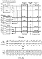
- x 1 , x 2 , x 3 , x 4 represent four signal lines of I2S on the peripheral side; X 1 , X 2 , X 3 , X 4 represent four signal lines of I2S on the host side; and four signal lines of I2S are serial bit clock SCLK, frame clock LRCK, serial out data SDATA_O, serial in data SDATA_I respectively.
- the four signals x 1 , x 2 , x 3 and x 4 of I2S are crossed over the USB Type-C interface and the forward and reverse plug channel switching module from the B6, B7, A8 and B8 pins of the USB Type-C Plug on the peripheral side and sent to X 1 , X 2 , X 3 and X 4 on the host side.
- the circuit principle of I2S channel establishment is shown in FIG. 3A , FIG. 3B , FIG. 4A and FIG. 4B . As shown in FIG.
- X 1 , X 2 , X 3 and X 4 represent that, when the four signal lines of I2S on the host side are plugged in the forward direction, three switches SW 0 , SW 1 and SW 2 are simultaneously thrown upward, and x 1 , x 2 , x 3 and x 4 represent four signal lines of I2S on the peripheral side.
- the forward and reverse plug channel switching module is formed by three two-way single-pole double-throw switches MUX 0 , MUX 1 and MUX 2 , and the two-way single-pole double-throw switch includes a switch control signal SW and a channel on-off enable signal EN.
- FIG. 3B The corresponding relationship between the plug and the receptacle when plugged in the forward direction is shown in FIG. 3B .
- X 1 , X 2 , X 3 and X 4 represent that, when the four signal lines of I2S on the host side are plugged in the reverse direction, three switches SW 0 , SW 1 and SW 2 are simultaneously thrown downward, and X 1 , X 2 , X 3 and X 4 represent four signal lines of I2S on the peripheral side.
- the USB Type-C interface supports forward plug and reverse plug.
- the CC controller monitors forward plug and reverse plug and reports to the CPU system module.
- An instruction for forward and reverse plug channel switching is issued by the CPU system module and is executed through controlling 3 switch control lines SW 0 , SW 1 and SW 2 to be simultaneously thrown upwards or downwards.
- a channel configuration (CC) bus among the interaction signals between the host and the peripheral is used for completing identification of a forward and reverse plug connection state of the host.
- the CC bus is also used as an interaction bus between the host and the peripheral to complete the identification of the forward and reverse plug connection state of the host and CC behavior, such as device identification and control setting of the audio module, as shown in FIG. 5A and FIG. 5B .
- FIG. 5A and FIG. 5B are taken from “USB Type-C Cable and Connector Specification Release 1.2”, Mar. 25, 2016.
- Rp and Rd are introduced. Variations are possible in an actual device, for example, Rp may be replaced by a current source.
- a DFP CC end has Rp pull-up, and a UFP CC end has Rd pull-down; the Vconn pin in the Power Cable has Ra pull-down (in some cases a pure resistor, and in some cases a load); the DFP needs to be capable of identifying Rd and Ra, that is, the DFP determines a connection of UFP or a Power Cable and CC direction by identifying Rd and Ra; the UFP determines a plug direction by a voltage (CC when the voltage exceeds OV) of two CC pins.
- USB2.0 D+/D ⁇ data line is used as the interaction bus between the host and the peripheral to complete the device identification, the control setting of the audio module, and the like.
- the power supply line and the ground line among the interaction signals between the host and the peripheral are used for completing power transmission between the host and the peripheral, and providing a signal mirror loop of the USB, I2S and CC buses.
- Table 1 shows a USB Type-C host state identification table.
- the host determines whether the UFP or the Power Cable is connected by sensing resistance of two CC pins, and determines forward and reverse plug, Debug Access Mode connected, or Audio Accessory Mode connected.
- DFP is an abbreviation of Downstream Facing Port, which represents a downlink Port, and may be referred to as a host CC controller herein
- UFP is an abbreviation of Upstream Facing Port, which represents an uplink Port, and may be referred to as a device control module on the peripheral side herein.
- An interaction flow between the host and the peripheral includes steps described below.
- the interaction between the host and the peripheral may be performed in two manners: a CC bus interaction manner and a USB bus interaction manner.
- the USB Type-C Cable Controller on the peripheral side is used as a device controller, is externally connected to the CC bus, and internally controls the peripheral CODEC module through a control bus I2C, SPI, GPIO or the like.
- the specific flow is shown in FIG. 6 .
- the USB Device Controller on the peripheral side is used as the device controller, is externally connected to a USB D+/D ⁇ bus of the USB Type-C Plug, and is internally connected to the control bus I2C, SPI, GPIO or the like of the peripheral CODEC module.
- the specific process is shown in FIG. 7 .
- the I2S Naked Over USB Type-C architecture can address poor anti-interference capability, high power consumption, and large delay in the UAC earphone and analog-digital mixed USB Type-C earphone. Because the pure digital signal transmission can be used, the anti-interference capability is strong; because the I2S bus is a low power consumption bus, the battery life is long; and the I2S bus is a commonly used digital audio bus in the mobile communication platform and is used for transmitting call audio data between a baseband processor and an audio CODEC in the host, the call delay is low and the delay is small, which meets requirements of mobile call.
- the present embodiment provides a terminal, which is connected to a terminal peripheral connected to the terminal through an I2S bus channel.
- the terminal 80 includes a first audio module 802 and a USB receptacle 804 .
- the first audio module 802 is connected to USB receptacle in a terminal through an audio bus channel and is configured to send a signal to be sent to the USB receptacle.
- the first audio module 802 may be an audio CODEC, a MIC DAC, an earphone DAC, an earphone amplifier, an earphone wire control identification circuit, an encoder, and the like in the terminal.
- the USB receptacle 804 is configured to provide a physical connection interface between the terminal and a terminal peripheral.
- the USB receptacle is a USB Type-C receptacle, and in this case, as shown in FIG. 9 , the terminal further includes a forward and reverse plug channel switching module 806 which is disposed on an audio bus (such as I2S bus) and separately connected to the first audio module and the USB receptacle through the audio bus (such as I2S bus).
- an audio bus such as I2S bus
- the terminal may further include a Channel Configuration (CC) controller 808 .
- the CC controller 808 is configured to identify a forward and reverse plug connection state when the terminal peripheral is connected to the terminal and notify the above-mentioned forward and reverse plug connection state to the system module 810 used for performing information interaction with the network side.
- CC Channel Configuration
- the system module 810 is separately connected to the first audio module 802 and the forward and reverse plug channel switching module 806 , and is configured to control the forward and reverse plug channel switching module 806 to establish an audio bus (such as I2S bus) channel according to the forward and reverse plug connection state.
- the system module 810 may include, but is not limited to an application processor, a baseband processor, a memory, a radio frequency transceiver and other hardware system platform chips.
- the system module 810 completes functions such as signal transceiving conversion with a mobile network base station and is also responsible for completing establishment control and signal interaction of a host audio naked channel.
- the audio bus is an I2S bus.
- An I2S bus in an I2S bus channel is crossed over the forward and reverse plug channel switching module and is connected to pins B6, B7, A8 and B8 in a USB Type-C receptacle.
- the I2S bus includes the following signal lines: serial bit clock SCLK, frame clock LRCK, serial out data SDATA_O, and serial in data SDATA_I.
- the present embodiment further provides a terminal peripheral.
- the terminal peripheral 10 includes a second audio module 102 and a USB plug 104 .
- the second audio module is connected to a USB plug in a terminal peripheral through an I2S bus channel and is configured to perform signal transmission with the USB plug through the audio bus channel.
- the USB plug is configured to be connected to a USB receptacle of a terminal accessed by the terminal peripheral.
- the USB plug 104 is a USB Type-C plug.
- the terminal peripheral 10 may further include a device control module 106 .
- the device control module 106 is connected to the USB Type-C plug 104 and used for maintaining description information of the terminal peripheral, where the description information includes at least one of: identification information used for identifying that the terminal peripheral supports a connection of the second audio module to the USB Type-C plug through an I2S channel; or a mapping relationship between an I2S bus in the I2S bus channel and pins of the USB Type-C plug.
- the device control module 106 is further configured to be connected to the second audio module through the I2C bus and used for initializing configuration of the second audio module.
- the device control module 106 is further configured to control the second audio module to establish the I2S bus channel and send first notification information to the terminal, and the first notification information is used for notifying the terminal that the terminal peripheral has established the audio bus (such as I2S bus) channel.
- the device control module 106 is further configured to receive second notification information sent by the terminal, and the second notification information is used for notifying the terminal peripheral that the terminal has established the audio bus (such as I2S bus) channel.
- the audio bus such as I2S bus
- an I2S in the I2S bus channel is connected to pins B6, B7, A8 and B8 of the USB Type-C plug; or the I2S is connected to pins A6, A7, A8 and B8 of the USB Type-C plug; or the I2S is connected to pins A6, A7, B6 and B7 of the USB Type-C plug.
- the I2S includes the following signal lines: serial bit clock SCLK, frame clock LRCK, serial out data SDATA_O, and serial in data SDATA_I.
- the terminal peripheral may further include a switching module 108 .
- the switching module 108 is configured to conduct the I2S bus channel when the terminal supports a first working mode, and close the I2S bus channel and open a USB channel between the second audio module and the USB plug when the terminal supports a second working mode, the USB channel includes a USB-to-I2S bridge circuit, where in the first working mode, a first audio module in the terminal is connected to a USB receptacle through the I2S bus channel, and in the second working mode, the first audio module is connected to the USB receptacle through the USB channel.
- the terminal peripheral may also be divided into a single-mode digital earphone and a dual-mode digital earphone, which are explained in detail below.
- a device controller and a control bus on the peripheral side two implementations of the I2S over a USB Type-C interface are provided.
- the USB Type-C Cable Controller is used as a device controller to design a single-mode digital earphone with the I2S over the USB Type-C interface, and in the other implementation, the USB Device Controller as a device controller to provide a dual-mode digital earphone with the I2S over the USB Type-C interface.
- the single-mode digital earphone with the I2S over the USB Type-C interface is an audio peripheral based on the I2S Naked Over USB Type-C architecture.
- An earphone with the I2S over the USB Type-C interface (referred to as I2S USBC earphone) is taken as an example for description.
- the I2S USBC earphone has the following features: transmitting the audio signals to the host through the I2S; transmitting the control signals to the host through the CC bus; transmitting operation information of earphone wire control keys (volume increase and decrease, connect and hang up, pause, fast forward, and other functions) to the host through the CC; and the I2S data line using B6/B7/A8/B8 pins of the USB Type-C Plug.
- FIG. 12 An implementation block diagram of the I2S USBC earphone is shown in FIG. 12 .
- architecture of the I2S USBC earphone is formed by an earphone, a host, and interaction signals between the host and the earphone.
- the I2S is directly crossed over the USB Type-C interface to transmit the audio signals.
- the control signals and data signals are transmitted through the CC bus.
- An earphone side part includes a device control module, an earphone CODEC module, an earphone power supply module, an earphone USB Type-C Plug and an earphone body.
- a host side part not only includes a CPU system module and a host CODEC module, but also must include a CC controller module, a power supply management module, a forward and reverse plug channel switching module and a USB Receptacle.
- Interaction signals between the host and the earphone include the I2S bus, the CC bus, a power supply line, and a common ground line.
- the device controller module uses a USB Type-C Cable Controller form, and the device is identified as a special EMCA electronically marked cable.
- the device control module has a function of identifying basic information of the I2S USBC earphone and the basic information includes that the earphone is an I2S bus USB Type-C interface earphone and that the I2S is defined at pins B6/B7/A8/B8.
- the device controller module communicates with the CC controller module on the host side by using a CC single bus to complete report of the earphone identification information.
- the device controller module communicates with the earphone Audio module by using the I2C bus as an initialization bus to complete initialization of the earphone CODEC module. Power is supplied between the device control module and the CC controller module on the host side through the VCONN.
- EMCA also referred to Electronically Marked Cable Assembly
- EMCA conforms to the “SOP′/SOP” Communication with Cable Plugs” specification in the USB PD protocol.
- the USB PD is a Bi-Phase Mark (BMC) code signal, and the previous USB is Frequency-shift Keying (FSK); the USB PD is transmitted on the CC pins, and the USB PD has a Vector Defined Messages (VDM) function, which defines a device ID for defining an earphone label and can also define a register mapping table of the earphone CODEC module. The host can set the register of the earphone CODEC module through the register mapping table.
- VDM Vector Defined Messages
- the earphone CODEC module includes an audio CODEC, an MIC DAC, an earphone DAC, an earphone amplifier, earphone wire control identification and code, and the like, and has an I2C interface and an I2S interface, where the I2S interface is directly connected to B6/B7/A8/B8 pins of the USB Type-C Plug.
- the earphone power supply module acquires power from VBUS of the USB Type-C Plug, converts the power into voltages required by each module on the earphone side, and manages a power-on sequence.
- the earphone body includes an earphone horn, an MIC, wire control keys, an earphone cable and the like, that is all parts of a traditional 3.5 mm earphone except a plug.
- FIG. 13 An interaction flow between the I2S USBC earphone and the host is shown in FIG. 13 .
- the I2S USBC earphone power consumption is low, and an I2S low power consumption digital audio bus is used for signal transmission; compared with UAC, power consumption waste of I2S to USB and USB to I2S and power consumption waste in a case that the AP cannot sleep when the USB works are further saved.
- the I2S USBC earphone the cost is low.
- a USB-I2S bridge conversion chip is not needed; compared with the analog-digital mixed earphone, a rear-stage circuit does not need to be added with a two-way earphone switching chip; compared with the analog-digital mixed earphone with time division multiplexing channels, a front-stage USB of a USB port and an earphone signal switch are further saved. 3) HIFI performance of the I2S USBC earphone is more guaranteed. Firstly, the pure digital signals are not easily interfered; and secondly, compared with the analog-digital mixed earphone, the rear-stage circuit does not need to be added with the two-way earphone switch, so that insertion loss of the audio signal caused by the switch is avoided.
- the I2S USBC earphone can completely meet the requirement of the mobile call time delay.
- An audio channel is completely the same as a traditional mobile phone, and natural call delay is the same as the traditional mobile phone.
- the I2S USBC earphone traditional audio architecture is used in software, the earphone development difficulty is relatively lower, a full digitalization process of the earphone is more advanced, and the product is easier to seize market opportunities.
- the design of the digital earphone which completely meets the requirement of the mobile call time delay under the UAC architecture needs to wait for improvement of the UAC standard and optimization of a host hardware platform and software architecture, and can be realized in the future. 2.
- the USB Device Controller on the peripheral side is used as a device control module, externally uses the USB D+/D ⁇ bus as an interaction bus to connect to the USB Type-C Plug, internally is connected to the peripheral CODEC module through an control bus such as I2C, SPI, GPIO, or the like.
- I2C I2C
- SPI SPI
- GPIO GPIO
- another I2S Naked Over USB Type-C interface digital audio peripheral architecture of the I2S Over USB Type-C interface can be designed. Since some USB Device controllers have a U2S-I2S bridge function, it is easy to design an audio peripheral which supports not only an I2S Naked Over USB Type-C interface architecture, but also the UAC function.
- an earphone peripheral is still used as an example for description, that is in a dual-mode digital earphone, mode 1 is I2S Naked Over USB Type-C architecture and mode 2 is UAC architecture based on I2S Over USB technology.
- mode 1 is I2S Naked Over USB Type-C architecture
- mode 2 is UAC architecture based on I2S Over USB technology.
- the earphone hereinafter the earphone referred to as an I2S & UAC dual-mode earphone.
- the I2S & UAC dual-mode earphone has features described below.
- the earphone has a UAC digital earphone function.
- the earphone has an I2S USBC digital earphone function.
- the earphone has two working mode, a UAC mode and an I2S USBC mode, and the I2S USBC mode has priority.
- the earphone transmits control signals, audio signals and data signals with the host through the USB bus.
- the earphone transmits audio signals with the host through the I2S bus, and transmits control signals and human interface interaction signals (wire control keys for volume increase and decrease, call, pause, and the like) through the USB D+/D ⁇ bus.
- the I2S data line uses B6/B7/A8/B8 pins of the USB Type-C Plug.
- a device label is implemented through a USB Device label manner.
- FIG. 14 The circuit principle of the earphone is shown in FIG. 15 . As shown in FIG. 14 and FIG. 15 ,
- the architecture of the I2S & UAC dual-mode earphone is formed by an earphone, a host, and an interaction signal channel between the host and the earphone.
- the earphone has two working modes: a working mode 1 and a working mode 2.
- the working mode 1 i.e. the I2S USBC mode
- the I2S is directly crossed over the USB Type-C interface to transmit the audio signals
- the working mode 2 i.e. the UAC mode
- the I2S is packed into a USB data format (I2S Over USB) to transmit the audio signals.
- the control signals and data signals are transmitted through the USB D+/D ⁇ bus.
- An earphone side part includes a device control module, an earphone CODEC module, an earphone power supply module, an earphone USB Type-C Plug, an Rd ground resistance and an earphone body.
- a host side part not only includes a CPU system module and a host CODEC module, but also must include a CC controller module, a power supply management module, a forward and reverse plug channel switching module and a USB Receptacle.
- Interaction signals between the host and the earphone include the USB bus, the I2S bus, the CC bus, the power supply line, and the common ground line.
- x 1 /X 1 I2S2_SCLK
- x 2 /X 2 I2S2_LRCK
- x 3 /X 3 I2S2_SDATA_O
- x 4 /X 4 I2S2_SDATA_I.
- pins of SDATA_O and SDATA_I of the I2S between a Master chip and a Slave chip should be cross-connected.
- the device control module has a function of identifying basic information of the I2S & UAC earphone.
- the basic information includes that this is an I2S & UAC dual-mode earphone that supports the I2S USBC earphone mode and the UAC mode; the I2S bus is defined on the B6/B7/A8/B8 pins of the USB Type-C.
- the device control module communicates with the CPU system module on the host side through the USB D+/D ⁇ bus to complete report of earphone identification information and complete initialization of the earphone CODEC module.
- the device control module transmits audio upstream and downstream data by using the I2S bus, transmits control and status data by using the I2C bus, and transmits firmware data of the earphone CODEC module by using the SPI bus, with the earphone CODEC module.
- the device control module also completes a mode switching function of the I2S USBC earphone mode and the UAC mode.
- the earphone body includes an earphone horn, an MIC, wire control keys, an earphone cable and the like, that is all parts of a traditional 3.5 mm earphone except a plug.
- the earphone power supply module acquires power from VBUS of the USB Type-C Plug, converts the power into voltages required by each module on the earphone side, and manages a power-on sequence.
- the Rd ground resistance identifies that this is a USB Device.
- the CC bus on the host side detects the ground resistance to complete plug identification of the earphone USB Device.
- the earphone CODEC module includes an audio I2S HUB, a CODEC, an MIC DAC, an earphone DAC, an earphone amplifier, earphone wire control identification and code, and the like, and has an I2C interface and dual I2S interfaces, where one I2S interface is directly connected to B6/B7/A8/B8 pins of the USB Type-C Plug, and another I2S interface is connected to an I2S interface of the device controller (with a USB-I2S bridge).
- FIG. 16 A block diagram of the earphone CODEC module is shown in FIG. 16 .
- the I2S Hub in FIG. 16 can be implemented by using a low power consumption FPGA, and also can be implemented by using an Audio DSP.
- the I2S2 channel must have an I2S on-off module, which is on or off by default when powered on. Because A6 and B6 of a USB Type-C receptacle port of a general host are shorted, A7 and B7 are shorted, when the dual-mode earphone is plugged into the general host, pins A6 and B6, A7 and B7 of a USB Type-C plug port on the earphone side will be shorted from the host side.
- a use flow of the I2S & UAC dual-mode earphone includes steps described below.
- the earphone works in a mode 1, that is the I2S USBC mode.
- a work flow of the dual-mode earphone in the I2S USBC mode is shown in FIG. 17 .
- the I2S & UAC dual-mode earphone has good versatility, the I2S USBC mode is used when the host meets the I2S Naked Over USB Type-C architecture, and the UAC mode is used when the host only meets the UAC architecture.
- the I2S & UAC dual-mode earphone uses the I2S USBC mode, power consumption is low, and the I2S low power consumption digital audio bus is used for audio signal transmission; compared with UAC, power consumption waste of I2S to USB and USB to I2S and power consumption waste in a case that the AP cannot sleep when the USB works are further saved.
- the cost is low.
- a rear-stage circuit does not need to be added with a two-way earphone switching chip; compared with the analog-digital mixed earphone with time division multiplexing channels, a front-stage USB of a USB port and an earphone signal switch are further saved. 4) HIFI performance of the I2S & UAC dual-mode earphone is more guaranteed. Firstly, the pure digital signals are not easily interfered; and secondly, compared with the analog-digital mixed earphone, the rear-stage circuit does not need to be added with the two-way earphone switch, so that insertion loss of the audio signal caused by the switch is avoided.
- the USB and the earphone signal switch are further saved, thereby further avoiding audio signal insertion loss caused by the switch.
- the I2S & UAC dual-mode earphone uses the I2S USBC mode, the time delay requirement of the mobile call can be completely met.
- An audio channel is completely the same as a traditional mobile phone, and natural call delay is the same as the traditional mobile phone.
- the I2S & UAC dual-mode earphone traditional audio architecture is used in software, the earphone development difficulty is relatively lower, a full digitalization process of the earphone is more advanced, and the product is easier to seize market opportunities.
- the design of the digital earphone which completely meets the requirement of the mobile call time delay under the pure UAC architecture needs to wait for improvement of the UAC standard and optimization of a host hardware platform and software architecture, and can be realized in the future.
- FIG. 19 is a flowchart of a signal sending method according to an embodiment of the present application. As shown in FIG. 19 , the method includes steps described below.
- a terminal sends a signal to be sent to a USB receptacle in the terminal through an I2S bus channel, and in some embodiments, the USB receptacle is a USB Type-C receptacle.
- step S 1904 the terminal sends the signal to be sent to a terminal peripheral through the USB receptacle.
- the method in the embodiments described above may be implemented by software plus a necessary general-purpose hardware platform, or may of course be implemented by hardware. However, in many cases, the former is more often used.
- the present application substantially, or the part contributing to the existing art, may be embodied in the form of a software product.
- the software product is stored on a storage medium (such as a ROM/RAM, a magnetic disk or an optical disk) and includes several instructions for enabling a terminal device (which may be a mobile phone, a computer, a server or a network device) to execute the method according to each embodiment of the present application.
- This embodiment provides a signal receiving method. As shown in FIG. 20 , the method includes steps described below.
- a terminal peripheral receives a signal from a terminal through a USB plug of the terminal peripheral, and in some embodiments, the USB plug is a USB Type-C plug.
- step S 2004 through the I2S bus channel, the signal is sent to a second audio module in the terminal peripheral.
- the terminal peripheral before sending, through the I2S bus channel, the signal to the second audio module in the terminal peripheral, the terminal peripheral determines a working mode of the terminal; the I2s bus channel is conducted when the working mode is a first working mode, and the audio bus channel is closed and a USB channel between the second audio module and the USB plug is opened when the terminal supports a second working mode, where in the first working mode, a first audio module in the terminal is connected to a USB receptacle through the audio bus channel, and in the second working mode, the first audio module is connected to the USB receptacle through the USB channel.
- each of the above-mentioned modules or steps of the present application may be implemented by a general-purpose computing device, the modules or steps may be concentrated on a single computing device or distributed on a network formed by multiple computing devices, and in some embodiments, the modules or steps may be implemented by program codes executable by the computing devices, so that modules or steps may be stored in a storage device and executed by the computing devices.
- the illustrated or described steps may be executed in sequences different from those described herein, or the modules or steps may be made into various integrated circuit modules separately, or multiple modules or steps therein may be made into a single integrated circuit module for implementation. In this way, the present application is not limited to any specific combination of hardware and software.
Landscapes
- Engineering & Computer Science (AREA)
- Theoretical Computer Science (AREA)
- Physics & Mathematics (AREA)
- General Engineering & Computer Science (AREA)
- General Physics & Mathematics (AREA)
- Acoustics & Sound (AREA)
- Signal Processing (AREA)
- Information Transfer Systems (AREA)
- Headphones And Earphones (AREA)
Abstract
Description
| TABLE 1 | ||||||
| Dp and Dn | ||||||
| positions of | ||||||
| Number | CC1 | CC2 | | Position | plug | |
| 1 | OPEN | OPEN | Nothing | N/A | / | |
| connected | (Unplug) | |||||
| 2 | Rd | OPEN | UFP connected | 1 (Forward | Dp, A6 | |
| plug) | ||||||
| 3 | OPEN | Rd | 2 (Reverse | Dn, A7 | ||
| plug) | ||||||
| 4 | OPEN | Ra | Powered | 1 (Forward | Dp, A6 | |
| Cable/No UFP | plug) | |||||
| 5 | Ra | OPEN | connected | 2 (Reverse | Dn, A7 | |
| plug) | ||||||
| 6 | Rd | Ra | Powered | 1 (Forward | Dp, A6 | |
| Cable/UFP | plug) | |||||
| 7 | Ra | Rd | connected | 2 (Reverse | Dn, A7 | |
| plug) | ||||||
| 8 | Rd | Rd | Debug | N/A (Fail to | Dp, A6, B6 | |
| Accessory Mode | identify | Dn, A7, B7 | ||||
| connected | forward or | |||||
| (Appendix B) | reverse | |||||
| plug) | ||||||
| 9 | Ra | Ra | Audio Adapter | N/A (Fail to | Dp, A6, and | |
| Accessory | identify | B6 are shorted | ||||
| Mode | forward or | Dn, A7, and | ||||
| connected | reverse | B7 are shorted | ||||
| (Appendix B) | plug) | |||||
2) As for the I2S USBC earphone, the cost is low. On the earphone side, a USB-I2S bridge conversion chip is not needed; compared with the analog-digital mixed earphone, a rear-stage circuit does not need to be added with a two-way earphone switching chip; compared with the analog-digital mixed earphone with time division multiplexing channels, a front-stage USB of a USB port and an earphone signal switch are further saved.
3) HIFI performance of the I2S USBC earphone is more guaranteed. Firstly, the pure digital signals are not easily interfered; and secondly, compared with the analog-digital mixed earphone, the rear-stage circuit does not need to be added with the two-way earphone switch, so that insertion loss of the audio signal caused by the switch is avoided. Compared with the analog-digital mixed earphone with time division multiplexing channels, the USB and the earphone signal switch are further saved, thereby further avoiding audio signal insertion loss caused by the switch.
4) The I2S USBC earphone can completely meet the requirement of the mobile call time delay. An audio channel is completely the same as a traditional mobile phone, and natural call delay is the same as the traditional mobile phone.
5) In the I2S USBC earphone, traditional audio architecture is used in software, the earphone development difficulty is relatively lower, a full digitalization process of the earphone is more advanced, and the product is easier to seize market opportunities. The design of the digital earphone which completely meets the requirement of the mobile call time delay under the UAC architecture needs to wait for improvement of the UAC standard and optimization of a host hardware platform and software architecture, and can be realized in the future.
2. Dual-Mode Digital Earphone
3) As for the I2S & UAC dual-mode earphone, the cost is low. 3) Compared with the analog-digital mixed earphone, a rear-stage circuit does not need to be added with a two-way earphone switching chip; compared with the analog-digital mixed earphone with time division multiplexing channels, a front-stage USB of a USB port and an earphone signal switch are further saved.
4) HIFI performance of the I2S & UAC dual-mode earphone is more guaranteed. Firstly, the pure digital signals are not easily interfered; and secondly, compared with the analog-digital mixed earphone, the rear-stage circuit does not need to be added with the two-way earphone switch, so that insertion loss of the audio signal caused by the switch is avoided. Compared with the analog-digital mixed earphone with time division multiplexing channels, the USB and the earphone signal switch are further saved, thereby further avoiding audio signal insertion loss caused by the switch.
5) When the I2S & UAC dual-mode earphone uses the I2S USBC mode, the time delay requirement of the mobile call can be completely met. An audio channel is completely the same as a traditional mobile phone, and natural call delay is the same as the traditional mobile phone.
6) As for the I2S & UAC dual-mode earphone, traditional audio architecture is used in software, the earphone development difficulty is relatively lower, a full digitalization process of the earphone is more advanced, and the product is easier to seize market opportunities. The design of the digital earphone which completely meets the requirement of the mobile call time delay under the pure UAC architecture needs to wait for improvement of the UAC standard and optimization of a host hardware platform and software architecture, and can be realized in the future.
Claims (15)
Applications Claiming Priority (3)
| Application Number | Priority Date | Filing Date | Title |
|---|---|---|---|
| CN201710948958.7A CN109660913B (en) | 2017-10-12 | 2017-10-12 | Terminal, terminal peripheral, signal transmission system and signal sending and receiving method |
| CN201710948958.7 | 2017-10-12 | ||
| PCT/CN2018/110144 WO2019072252A1 (en) | 2017-10-12 | 2018-10-12 | Terminal, terminal peripheral, signal transmission system and signal sending and receiving method |
Publications (2)
| Publication Number | Publication Date |
|---|---|
| US20210200705A1 US20210200705A1 (en) | 2021-07-01 |
| US11403245B2 true US11403245B2 (en) | 2022-08-02 |
Family
ID=66100387
Family Applications (1)
| Application Number | Title | Priority Date | Filing Date |
|---|---|---|---|
| US16/755,616 Active US11403245B2 (en) | 2017-10-12 | 2018-10-12 | Terminal, terminal peripheral, signal transmission system and signal sending and receiving method |
Country Status (3)
| Country | Link |
|---|---|
| US (1) | US11403245B2 (en) |
| CN (1) | CN109660913B (en) |
| WO (1) | WO2019072252A1 (en) |
Families Citing this family (5)
| Publication number | Priority date | Publication date | Assignee | Title |
|---|---|---|---|---|
| KR102600482B1 (en) * | 2018-02-23 | 2023-11-10 | 삼성전자주식회사 | Electronic apparatus and method for outputting a alarm, and system including a locking device connected to the electronic device |
| CN115102929B (en) * | 2021-03-03 | 2024-02-13 | 阿里巴巴(中国)有限公司 | Audio processing system, intermediate layer chip and audio processing device |
| US11513575B1 (en) * | 2021-06-14 | 2022-11-29 | Dell Products L.P. | Dynamic USB-C mode configuration |
| CN114286272B (en) * | 2021-12-17 | 2023-05-16 | 华勤技术股份有限公司 | Time delay test system, method and related device of true wireless earphone |
| CN115994109B (en) * | 2023-03-21 | 2023-07-21 | 合肥集创微电子科技有限公司 | Data transmission method based on Type-C physical interface and electronic equipment |
Citations (14)
| Publication number | Priority date | Publication date | Assignee | Title |
|---|---|---|---|---|
| US20060166627A1 (en) * | 2005-01-21 | 2006-07-27 | Crawley Casimir J | Staged locking of two phase locked loops |
| CN201359725Y (en) | 2009-01-21 | 2009-12-09 | 青岛海信移动通信技术股份有限公司 | USB interface circuit and portable hand-held device provided with the circuit |
| US20100054498A1 (en) * | 2008-08-26 | 2010-03-04 | Nelson Sollenberger | Method and system for audio level detection and control |
| US20140172422A1 (en) * | 2012-12-17 | 2014-06-19 | Yaron Hefetz | Secured audio channel for voice communication |
| CN104063348A (en) | 2014-06-17 | 2014-09-24 | 武汉天喻信息产业股份有限公司 | Device and method for realizing compatible USB (Universal Serial Bus) communication and audio communication |
| CN105120404A (en) | 2015-07-31 | 2015-12-02 | 华为技术有限公司 | Audio equipment, terminal equipment and electronic equipment |
| CN105677611A (en) | 2015-12-31 | 2016-06-15 | 北京小鸟看看科技有限公司 | Portable device and method for controlling HDMI signal outputting |
| US20160285757A1 (en) * | 2015-03-26 | 2016-09-29 | Intel Corporation | Selectively enabling first and second communication paths using a repeater |
| CN106021150A (en) | 2016-04-29 | 2016-10-12 | 青岛海信电器股份有限公司 | Type-C interface equipment, communication system and communication method |
| CN205987323U (en) | 2016-08-05 | 2017-02-22 | 深圳市金立通信设备有限公司 | Audio processing circuit and terminal based on type c interface |
| WO2017065769A1 (en) | 2015-10-15 | 2017-04-20 | Hewlett-Packard Development Company, L.P. | Utilizing pins on a universal serial bus (usb) type-c connector for a data signal |
| CN106792313A (en) | 2016-12-26 | 2017-05-31 | 深圳市飞易通科技有限公司 | Bluetooth DAB earphone |
| US20170280244A1 (en) * | 2015-09-11 | 2017-09-28 | Ess Technology, Inc. | Switchable Four-pole Jack For Supporting Balanced Headphones and Headset Operation in Mobile Applications |
| US20190110119A1 (en) * | 2016-03-29 | 2019-04-11 | Sony Corporation | Receiver and rf signal supply apparatus |
-
2017
- 2017-10-12 CN CN201710948958.7A patent/CN109660913B/en active Active
-
2018
- 2018-10-12 US US16/755,616 patent/US11403245B2/en active Active
- 2018-10-12 WO PCT/CN2018/110144 patent/WO2019072252A1/en not_active Ceased
Patent Citations (15)
| Publication number | Priority date | Publication date | Assignee | Title |
|---|---|---|---|---|
| US20060166627A1 (en) * | 2005-01-21 | 2006-07-27 | Crawley Casimir J | Staged locking of two phase locked loops |
| US20100054498A1 (en) * | 2008-08-26 | 2010-03-04 | Nelson Sollenberger | Method and system for audio level detection and control |
| CN201359725Y (en) | 2009-01-21 | 2009-12-09 | 青岛海信移动通信技术股份有限公司 | USB interface circuit and portable hand-held device provided with the circuit |
| US20140172422A1 (en) * | 2012-12-17 | 2014-06-19 | Yaron Hefetz | Secured audio channel for voice communication |
| CN104063348A (en) | 2014-06-17 | 2014-09-24 | 武汉天喻信息产业股份有限公司 | Device and method for realizing compatible USB (Universal Serial Bus) communication and audio communication |
| US20160285757A1 (en) * | 2015-03-26 | 2016-09-29 | Intel Corporation | Selectively enabling first and second communication paths using a repeater |
| CN105120404A (en) | 2015-07-31 | 2015-12-02 | 华为技术有限公司 | Audio equipment, terminal equipment and electronic equipment |
| US20170280244A1 (en) * | 2015-09-11 | 2017-09-28 | Ess Technology, Inc. | Switchable Four-pole Jack For Supporting Balanced Headphones and Headset Operation in Mobile Applications |
| WO2017065769A1 (en) | 2015-10-15 | 2017-04-20 | Hewlett-Packard Development Company, L.P. | Utilizing pins on a universal serial bus (usb) type-c connector for a data signal |
| US20180239718A1 (en) * | 2015-10-15 | 2018-08-23 | Hewlett-Packard Devlopment Company, L.P. | Utilizing Pins on a Universal Serial Bus (USB) Type-C Connector for a Data Signal |
| CN105677611A (en) | 2015-12-31 | 2016-06-15 | 北京小鸟看看科技有限公司 | Portable device and method for controlling HDMI signal outputting |
| US20190110119A1 (en) * | 2016-03-29 | 2019-04-11 | Sony Corporation | Receiver and rf signal supply apparatus |
| CN106021150A (en) | 2016-04-29 | 2016-10-12 | 青岛海信电器股份有限公司 | Type-C interface equipment, communication system and communication method |
| CN205987323U (en) | 2016-08-05 | 2017-02-22 | 深圳市金立通信设备有限公司 | Audio processing circuit and terminal based on type c interface |
| CN106792313A (en) | 2016-12-26 | 2017-05-31 | 深圳市飞易通科技有限公司 | Bluetooth DAB earphone |
Non-Patent Citations (3)
| Title |
|---|
| Chinese Search Report for corresponding application 2017109489587; dated Jun. 19, 2020. |
| International Search Report for corresponding application PCT/CN2018/110144 filed Oct. 12, 2018; dated Jan. 16, 2019. |
| TMS320C5515/14/05/04 DSP Inter-IC Sound (I2S) Bus User's Guide; Texas Instruments (Year: 2014). * |
Also Published As
| Publication number | Publication date |
|---|---|
| WO2019072252A1 (en) | 2019-04-18 |
| CN109660913B (en) | 2021-01-26 |
| CN109660913A (en) | 2019-04-19 |
| US20210200705A1 (en) | 2021-07-01 |
Similar Documents
| Publication | Publication Date | Title |
|---|---|---|
| CN108666826B (en) | Adapter, terminal equipment and adapter system | |
| US11403245B2 (en) | Terminal, terminal peripheral, signal transmission system and signal sending and receiving method | |
| CN107643994B (en) | Terminal, terminal peripheral, signal sending and receiving method and data transmission system | |
| CN108259803B (en) | Electronic terminal device, television terminal, signal input circuit and method | |
| US9414147B2 (en) | Method and device for earphone and USB to share micro-USB interface | |
| US7949802B2 (en) | Enhanced communication via a serial interface | |
| CN110879792B (en) | Electronic equipment and interface control method thereof | |
| WO2019072244A1 (en) | Terminal peripheral device and audio signal transmission method | |
| KR20170120611A (en) | Connectors for audio data transmission | |
| CN102281482A (en) | Function extension method and device thereof for earphone jack of smart phone | |
| CN110300318B (en) | USB terminal interface circuit and USB terminal interface circuit control method | |
| KR20190036165A (en) | Method for communicating multi devices using usb type c interface and electronic device for the same | |
| US20170329733A1 (en) | Multi-host supported universal serial bus hub and automobile head unit using the same | |
| CN102098035B (en) | Analog switch control circuit and mobile phone | |
| CN215895451U (en) | Switching circuit based on USB interface and audio equipment | |
| CN109346883B (en) | System for realizing positive and negative insertion of Type-C interface | |
| US9584919B2 (en) | Interface switching system and method for switching operation mode | |
| US10515025B2 (en) | Communication protocol adapter | |
| CN213151196U (en) | a signal converter | |
| CN103489431B (en) | A kind of display terminal | |
| CN211296823U (en) | Audio playing device | |
| JP2016509712A (en) | Data terminal, data transmission system, and hot swap control method | |
| CN207663436U (en) | Sound card audio conversion circuit and data transmission set | |
| WO2022170861A1 (en) | Data transmission method of electronic device, electronic device, and interface circuit | |
| CN223051711U (en) | TYPE-C interface circuit and electronic equipment |
Legal Events
| Date | Code | Title | Description |
|---|---|---|---|
| AS | Assignment |
Owner name: ZTE CORPORATION, CHINA Free format text: ASSIGNMENT OF ASSIGNORS INTEREST;ASSIGNOR:JIANG, YIXIANG;REEL/FRAME:052375/0429 Effective date: 20200406 |
|
| FEPP | Fee payment procedure |
Free format text: ENTITY STATUS SET TO UNDISCOUNTED (ORIGINAL EVENT CODE: BIG.); ENTITY STATUS OF PATENT OWNER: LARGE ENTITY |
|
| STPP | Information on status: patent application and granting procedure in general |
Free format text: NON FINAL ACTION MAILED |
|
| STPP | Information on status: patent application and granting procedure in general |
Free format text: RESPONSE TO NON-FINAL OFFICE ACTION ENTERED AND FORWARDED TO EXAMINER |
|
| STPP | Information on status: patent application and granting procedure in general |
Free format text: FINAL REJECTION MAILED |
|
| STPP | Information on status: patent application and granting procedure in general |
Free format text: ADVISORY ACTION MAILED |
|
| STPP | Information on status: patent application and granting procedure in general |
Free format text: DOCKETED NEW CASE - READY FOR EXAMINATION |
|
| STPP | Information on status: patent application and granting procedure in general |
Free format text: NOTICE OF ALLOWANCE MAILED -- APPLICATION RECEIVED IN OFFICE OF PUBLICATIONS |
|
| STPP | Information on status: patent application and granting procedure in general |
Free format text: PUBLICATIONS -- ISSUE FEE PAYMENT VERIFIED |
|
| STCF | Information on status: patent grant |
Free format text: PATENTED CASE |
|
| MAFP | Maintenance fee payment |
Free format text: PAYMENT OF MAINTENANCE FEE, 4TH YEAR, LARGE ENTITY (ORIGINAL EVENT CODE: M1551); ENTITY STATUS OF PATENT OWNER: LARGE ENTITY Year of fee payment: 4 |