US11402946B2 - Multi-chip synchronization in sensor applications - Google Patents
Multi-chip synchronization in sensor applications Download PDFInfo
- Publication number
- US11402946B2 US11402946B2 US16/457,489 US201916457489A US11402946B2 US 11402946 B2 US11402946 B2 US 11402946B2 US 201916457489 A US201916457489 A US 201916457489A US 11402946 B2 US11402946 B2 US 11402946B2
- Authority
- US
- United States
- Prior art keywords
- control circuits
- actively
- inductive sensors
- driven
- sensors
- Prior art date
- Legal status (The legal status is an assumption and is not a legal conclusion. Google has not performed a legal analysis and makes no representation as to the accuracy of the status listed.)
- Active, expires
Links
Images


Classifications
-
- G—PHYSICS
- G06—COMPUTING; CALCULATING OR COUNTING
- G06F—ELECTRIC DIGITAL DATA PROCESSING
- G06F3/00—Input arrangements for transferring data to be processed into a form capable of being handled by the computer; Output arrangements for transferring data from processing unit to output unit, e.g. interface arrangements
- G06F3/01—Input arrangements or combined input and output arrangements for interaction between user and computer
- G06F3/03—Arrangements for converting the position or the displacement of a member into a coded form
- G06F3/041—Digitisers, e.g. for touch screens or touch pads, characterised by the transducing means
- G06F3/0416—Control or interface arrangements specially adapted for digitisers
- G06F3/0418—Control or interface arrangements specially adapted for digitisers for error correction or compensation, e.g. based on parallax, calibration or alignment
- G06F3/04184—Synchronisation with the driving of the display or the backlighting unit to avoid interferences generated internally
-
- H—ELECTRICITY
- H03—ELECTRONIC CIRCUITRY
- H03K—PULSE TECHNIQUE
- H03K17/00—Electronic switching or gating, i.e. not by contact-making and –breaking
- H03K17/94—Electronic switching or gating, i.e. not by contact-making and –breaking characterised by the way in which the control signals are generated
- H03K17/965—Switches controlled by moving an element forming part of the switch
- H03K17/97—Switches controlled by moving an element forming part of the switch using a magnetic movable element
-
- G—PHYSICS
- G06—COMPUTING; CALCULATING OR COUNTING
- G06F—ELECTRIC DIGITAL DATA PROCESSING
- G06F3/00—Input arrangements for transferring data to be processed into a form capable of being handled by the computer; Output arrangements for transferring data from processing unit to output unit, e.g. interface arrangements
- G06F3/01—Input arrangements or combined input and output arrangements for interaction between user and computer
- G06F3/03—Arrangements for converting the position or the displacement of a member into a coded form
- G06F3/041—Digitisers, e.g. for touch screens or touch pads, characterised by the transducing means
- G06F3/044—Digitisers, e.g. for touch screens or touch pads, characterised by the transducing means by capacitive means
-
- G—PHYSICS
- G06—COMPUTING; CALCULATING OR COUNTING
- G06F—ELECTRIC DIGITAL DATA PROCESSING
- G06F3/00—Input arrangements for transferring data to be processed into a form capable of being handled by the computer; Output arrangements for transferring data from processing unit to output unit, e.g. interface arrangements
- G06F3/01—Input arrangements or combined input and output arrangements for interaction between user and computer
- G06F3/03—Arrangements for converting the position or the displacement of a member into a coded form
- G06F3/041—Digitisers, e.g. for touch screens or touch pads, characterised by the transducing means
- G06F3/045—Digitisers, e.g. for touch screens or touch pads, characterised by the transducing means using resistive elements, e.g. a single continuous surface or two parallel surfaces put in contact
-
- H—ELECTRICITY
- H03—ELECTRONIC CIRCUITRY
- H03K—PULSE TECHNIQUE
- H03K17/00—Electronic switching or gating, i.e. not by contact-making and –breaking
- H03K17/94—Electronic switching or gating, i.e. not by contact-making and –breaking characterised by the way in which the control signals are generated
- H03K17/965—Switches controlled by moving an element forming part of the switch
- H03K17/975—Switches controlled by moving an element forming part of the switch using a capacitive movable element
-
- H—ELECTRICITY
- H04—ELECTRIC COMMUNICATION TECHNIQUE
- H04J—MULTIPLEX COMMUNICATION
- H04J3/00—Time-division multiplex systems
- H04J3/02—Details
- H04J3/06—Synchronising arrangements
- H04J3/0635—Clock or time synchronisation in a network
-
- H—ELECTRICITY
- H03—ELECTRONIC CIRCUITRY
- H03K—PULSE TECHNIQUE
- H03K2217/00—Indexing scheme related to electronic switching or gating, i.e. not by contact-making or -breaking covered by H03K17/00
- H03K2217/94—Indexing scheme related to electronic switching or gating, i.e. not by contact-making or -breaking covered by H03K17/00 characterised by the way in which the control signal is generated
- H03K2217/94084—Transmission of parameters among sensors or between sensor and remote station
Definitions
- the present disclosure relates in general to electronic devices with user interfaces, (e.g., mobile devices, game controllers, instrument panels, etc.), and more particularly, resonant phase sensing of resistive-inductive-capacitive sensors for use in a system for mechanical button replacement in a mobile device, and/or other suitable applications.
- electronic devices with user interfaces e.g., mobile devices, game controllers, instrument panels, etc.
- resonant phase sensing of resistive-inductive-capacitive sensors for use in a system for mechanical button replacement in a mobile device, and/or other suitable applications.
- buttons to allow for interaction between a user of a mobile device and the mobile device itself.
- mechanical buttons are susceptible to aging, wear, and tear that may reduce the useful life of a mobile device and/or may require significant repair if malfunction occurs.
- the presence of mechanical buttons may render it difficult to manufacture mobile devices that are waterproof. Accordingly, mobile device manufacturers are increasingly looking to equip mobile devices with virtual buttons that act as a human-machine interface allowing for interaction between a user of a mobile device and the mobile device itself.
- virtual interface areas e.g., a virtual slider, interface areas of a body of the mobile device other than a touch screen, etc.
- virtual interface areas should look and feel to a user as if a mechanical button or other mechanical interface were present instead of a virtual button or virtual interface area.
- linear resonant actuators and other vibrational actuators (e.g., rotational actuators, vibrating motors, etc.) are increasingly being used in mobile devices to generate vibrational feedback in response to user interaction with human-machine interfaces of such devices.
- a sensor traditionally a force or pressure sensor
- detects user interaction with the device e.g., a finger press on a virtual button of the device
- the linear resonant actuator may vibrate to provide feedback to the user.
- a linear resonant actuator may vibrate in response to user interaction with the human-machine interface to mimic to the user the feel of a mechanical button click.
- sensors to detect user interaction with a human-machine interface, wherein such sensors provide acceptable levels of sensor sensitivity, power consumption, and size.
- One type of sensor that may be utilized to detect user interaction with a human-machine interface is a resistive-inductive-capacitive sensor.
- a local scheduler may be used to time-division multiplex sensor activation and measurement.
- the number of sensors may exceed the number of connections available within a single processing integrated circuit.
- approaches for synchronizing multiple processing integrated circuits for sensors may be desired.
- the disadvantages and problems associated with sensing in multiple-sensor applications may be reduced or eliminated.
- a system may include a plurality of actively-driven inductive sensors and a plurality of control circuits, each control circuit of the plurality of control circuits configured to control operation of a respective set of the actively-driven inductive sensors, each control circuit of the plurality of control circuits communicatively coupled to the other control circuits via a connection configured to distribute synchronization information among the plurality of control circuits.
- Each of the plurality of control circuits may further be configured to configure a schedule for controlling time-division multiplexed operation of its respective set of actively-driven inductive sensors and control time-division multiplexed operation of its respective set of actively-driven inductive sensors based on the schedule and the synchronization information in order to minimize interference among the plurality of actively-driven inductive sensors.
- a method may be provided for use in a system comprising a plurality of actively-driven inductive sensors and a plurality of control circuits, each control circuit of the plurality of control circuits configured to control operation of a respective set of the actively-driven inductive sensors, each control circuit of the plurality of control circuits communicatively coupled to the other control circuits via a connection configured to distribute synchronization information among the plurality of control circuits.
- the method may include configuring, by each control circuit of the plurality of control circuits, a schedule for controlling time-division multiplexed operation of its respective set of actively-driven inductive sensors and controlling, by each control circuit of the plurality of control circuits, time-division multiplexed operation of its respective set of actively-driven inductive sensors based on the schedule and the synchronization information in order to minimize interference among the plurality of actively-driven inductive sensors.
- a host device may include an enclosure, a plurality of actively-driven inductive sensors integral to the enclosure, and a plurality of control circuits integral to the enclosure, each control circuit of the plurality of control circuits configured to control operation of a respective set of the actively-driven inductive sensors, each control circuit of the plurality of control circuits communicatively coupled to the other control circuits via a connection configured to distribute synchronization information among the plurality of control circuits, and each of the plurality of control circuits
- Each of the plurality of control circuits may further be configured to configure a schedule for controlling time-division multiplexed operation of its respective set of actively-driven inductive sensors and control time-division multiplexed operation of its respective set of actively-driven inductive sensors based on the schedule and the synchronization information in order to minimize interference among the plurality of actively-driven inductive sensors.
- FIG. 1 illustrates a block diagram of selected components of an example mobile device, in accordance with embodiments of the present disclosure
- FIG. 2 illustrates a mechanical member separated by a distance from an inductive coil, in accordance with embodiments of the present disclosure
- FIG. 3 illustrates selected components of a model for a mechanical member and inductive coil that may be used in an inductive sensing system, in accordance with embodiments of the present disclosure
- FIGS. 4A-4C illustrates a diagram of selected components of an example resonant phase sensing system, in accordance with embodiments of the present disclosure
- FIG. 5 illustrates a diagram of selected components of an example resonant phase sensing system implementing time-division multiplexed processing of multiple resistive-inductive-capacitive sensors, in accordance with embodiments of the present disclosure
- FIG. 6 illustrates a diagram of selected components of an example resonant phase sensing system implementing time-division multiplexed processing of multiple resistive-inductive-capacitive sensors controlled by multiple processing integrated circuits, in accordance with embodiments of the present disclosure
- FIG. 7 illustrates an example timing diagram of time-division multiplexed processing of multiple resistive-inductive-capacitive sensors controlled by multiple processing integrated circuits, in accordance with embodiments of the present disclosure.
- FIG. 8 illustrates a diagram of selected components of another example resonant phase sensing system implementing time-division multiplexed processing of multiple resistive-inductive-capacitive sensors controlled by multiple processing integrated circuits, in accordance with embodiments of the present disclosure.
- FIG. 1 illustrates a block diagram of selected components of an example mobile device 102 , in accordance with embodiments of the present disclosure.
- mobile device 102 may comprise an enclosure 101 , a controller 103 , a memory 104 , a mechanical member 105 , a microphone 106 , a linear resonant actuator 107 , a radio transmitter/receiver 108 , a speaker 110 , and a resonant phase sensing system 112 .
- Enclosure 101 may comprise any suitable housing, casing, or other enclosure for housing the various components of mobile device 102 .
- Enclosure 101 may be constructed from plastic, metal, and/or any other suitable materials.
- enclosure 101 may be adapted (e.g., sized and shaped) such that mobile device 102 is readily transported on a person of a user of mobile device 102 .
- mobile device 102 may include but is not limited to a smart phone, a tablet computing device, a handheld computing device, a personal digital assistant, a notebook computer, a video game controller, or any other device that may be readily transported on a person of a user of mobile device 102 .
- Controller 103 may be housed within enclosure 101 and may include any system, device, or apparatus configured to interpret and/or execute program instructions and/or process data, and may include, without limitation a microprocessor, microcontroller, digital signal processor (DSP), application specific integrated circuit (ASIC), or any other digital or analog circuitry configured to interpret and/or execute program instructions and/or process data.
- controller 103 may interpret and/or execute program instructions and/or process data stored in memory 104 and/or other computer-readable media accessible to controller 103 .
- Memory 104 may be housed within enclosure 101 , may be communicatively coupled to controller 103 , and may include any system, device, or apparatus configured to retain program instructions and/or data for a period of time (e.g., computer-readable media).
- Memory 104 may include random access memory (RAM), electrically erasable programmable read-only memory (EEPROM), a Personal Computer Memory Card International Association (PCMCIA) card, flash memory, magnetic storage, opto-magnetic storage, or any suitable selection and/or array of volatile or non-volatile memory that retains data after power to mobile device 102 is turned off.
- RAM random access memory
- EEPROM electrically erasable programmable read-only memory
- PCMCIA Personal Computer Memory Card International Association
- Microphone 106 may be housed at least partially within enclosure 101 , may be communicatively coupled to controller 103 , and may comprise any system, device, or apparatus configured to convert sound incident at microphone 106 to an electrical signal that may be processed by controller 103 , wherein such sound is converted to an electrical signal using a diaphragm or membrane having an electrical capacitance that varies based on sonic vibrations received at the diaphragm or membrane.
- Microphone 106 may include an electrostatic microphone, a condenser microphone, an electret microphone, a microelectromechanical systems (MEMS) microphone, or any other suitable capacitive microphone.
- MEMS microelectromechanical systems
- Radio transmitter/receiver 108 may be housed within enclosure 101 , may be communicatively coupled to controller 103 , and may include any system, device, or apparatus configured to, with the aid of an antenna, generate and transmit radio-frequency signals as well as receive radio-frequency signals and convert the information carried by such received signals into a form usable by controller 103 .
- Radio transmitter/receiver 108 may be configured to transmit and/or receive various types of radio-frequency signals, including without limitation, cellular communications (e.g., 2G, 3G, 4G, LTE, etc.), short-range wireless communications (e.g., BLUETOOTH), commercial radio signals, television signals, satellite radio signals (e.g., GPS), Wireless Fidelity, etc.
- cellular communications e.g., 2G, 3G, 4G, LTE, etc.
- short-range wireless communications e.g., BLUETOOTH
- commercial radio signals e.g., television signals, satellite radio signals (e.g., GPS),
- a speaker 110 may be housed at least partially within enclosure 101 or may be external to enclosure 101 , may be communicatively coupled to controller 103 , and may comprise any system, device, or apparatus configured to produce sound in response to electrical audio signal input.
- a speaker may comprise a dynamic loudspeaker, which employs a lightweight diaphragm mechanically coupled to a rigid frame via a flexible suspension that constrains a voice coil to move axially through a cylindrical magnetic gap.
- a dynamic loudspeaker employs a lightweight diaphragm mechanically coupled to a rigid frame via a flexible suspension that constrains a voice coil to move axially through a cylindrical magnetic gap.
- Mechanical member 105 may be housed within or upon enclosure 101 , and may include any suitable system, device, or apparatus configured such that all or a portion of mechanical member 105 displaces in position responsive to a force, a pressure, or a touch applied upon or proximately to mechanical member 105 .
- mechanical member 105 may be designed to appear as a mechanical button on the exterior of enclosure 101 .
- Linear resonant actuator 107 may be housed within enclosure 101 , and may include any suitable system, device, or apparatus for producing an oscillating mechanical force across a single axis.
- linear resonant actuator 107 may rely on an alternating current voltage to drive a voice coil pressed against a moving mass connected to a spring. When the voice coil is driven at the resonant frequency of the spring, linear resonant actuator 107 may vibrate with a perceptible force.
- linear resonant actuator 107 may be useful in haptic applications within a specific frequency range.
- linear resonant actuator 107 any other type or types of vibrational actuators (e.g., eccentric rotating mass actuators) may be used in lieu of or in addition to linear resonant actuator 107 .
- actuators arranged to produce an oscillating mechanical force across multiple axes may be used in lieu of or in addition to linear resonant actuator 107 .
- a linear resonant actuator 107 based on a signal received from resonant phase sensing system 112 , may render haptic feedback to a user of mobile device 102 for at least one of mechanical button replacement and capacitive sensor feedback.
- mechanical member 105 and linear resonant actuator 107 may form a human-interface device, such as a virtual interface (e.g., a virtual button), which, to a user of mobile device 102 , has a look and feel of a mechanical button or other mechanical interface of mobile device 102 .
- a virtual interface e.g., a virtual button
- Resonant phase sensing system 112 may be housed within enclosure 101 , may be communicatively coupled to mechanical member 105 and linear resonant actuator 107 , and may include any system, device, or apparatus configured to detect a displacement of mechanical member 105 indicative of a physical interaction (e.g., by a user of mobile device 102 ) with the human-machine interface of mobile device 102 (e.g., a force applied by a human finger to a virtual interface of mobile device 102 ).
- resonant phase sensing system 112 may detect displacement of mechanical member 105 by performing resonant phase sensing of a resistive-inductive-capacitive sensor for which an impedance (e.g., inductance, capacitance, and/or resistance) of the resistive-inductive-capacitive sensor changes in response to displacement of mechanical member 105 .
- mechanical member 105 may comprise any suitable system, device, or apparatus which all or a portion thereof may displace, and such displacement may cause a change in an impedance of a resistive-inductive-capacitive sensor integral to resonant phase sensing system 112 .
- Resonant phase sensing system 112 may also generate an electronic signal for driving linear resonant actuator 107 in response to a physical interaction associated with a human-machine interface associated with mechanical member 105 . Detail of an example resonant phase sensing system 112 in accordance with embodiments of the present disclosure is depicted in greater detail below.
- a mobile device 102 in accordance with this disclosure may comprise one or more components not specifically enumerated above.
- FIG. 1 depicts certain user interface components
- mobile device 102 may include one or more other user interface components in addition to those depicted in FIG. 1 , including but not limited to a keypad, a touch screen, and a display, thus allowing a user to interact with and/or otherwise manipulate mobile device 102 and its associated components.
- FIG. 1 depicts only a single virtual button comprising mechanical member 105 and linear resonant actuator 107 for purposes of clarity and exposition, in some embodiments a mobile device 102 may have multiple virtual interfaces, each comprising a respective mechanical member 105 and linear resonant actuator 107 .
- resonant phase sensing system 112 may detect displacement of mechanical member 105 by performing resonant phase sensing of a resistive-inductive-capacitive sensor for which an impedance (e.g., inductance, capacitance, and/or resistance) of the resistive-inductive-capacitive sensor changes in response to displacement of mechanical member 105
- resonant phase sensing system 112 may primarily detect displacement of mechanical member 105 by using resonant phase sensing to determine a change in an inductance of a resistive-inductive-capacitive sensor.
- FIGS. 2 and 3 illustrate selected components of an example inductive sensing application that may be implemented by resonant phase sensing system 112 , in accordance with embodiments of the present disclosure.
- a host device may include without limitation, a portable and/or battery-powered mobile computing device (e.g., a laptop, notebook, or tablet computer), a gaming console, a remote control device, a home automation controller, a domestic appliance (e.g., domestic temperature or lighting control system), a toy, a machine (e.g., a robot) such as a robot, an audio player, a video player, and a mobile telephone (e.g., a smartphone).
- a portable and/or battery-powered mobile computing device e.g., a laptop, notebook, or tablet computer
- gaming console e.g., a gaming console
- a remote control device e.g., a remote control device
- a home automation controller e.g., a domestic appliance (e.g., domestic temperature or lighting control system)
- a toy e.g., a machine
- a machine e.g., a robot
- an audio player e.g., a video player
- FIG. 2 illustrates mechanical member 105 embodied as a metal plate separated by a distance d from an inductive coil 202 , in accordance with embodiments of the present disclosure.
- FIG. 3 illustrates selected components of a model for mechanical member 105 and inductive coil 202 that may be used in an inductive sensing system 300 , in accordance with embodiments of the present disclosure.
- inductive sensing system 300 may include mechanical member 105 , modeled as a variable electrical resistance 304 and a variable electrical inductance 306 , and may include inductive coil 202 in physical proximity to mechanical member 105 such that inductive coil 202 has a mutual inductance with mechanical member 105 defined by a variable coupling coefficient k.
- inductive coil 202 may be modeled as a variable electrical inductance 308 and a variable electrical resistance 310 .
- inductive coil 202 In operation, as a current I flows through inductive coil 202 , such current may induce a magnetic field which in turn may induce an eddy current inside mechanical member 105 .
- the coupling coefficient k, variable electrical resistance 304 , and/or variable electrical inductance 306 may also change in response to the change in distance. These changes in the various electrical parameters may, in turn, modify an effective impedance Z L of inductive coil 202 .
- FIG. 4A illustrates a diagram of selected components of an example resonant phase sensing system 112 A, in accordance with embodiments of the present disclosure.
- resonant phase sensing system 112 A may be used to implement resonant phase sensing system 112 of FIG. 1 .
- resonant phase sensing system 112 A may include a resistive-inductive-capacitive sensor 402 and a processing integrated circuit (IC) 412 A.
- IC processing integrated circuit
- Processing IC 412 A may be communicatively coupled to resistive-inductive-capacitive sensor 402 and may comprise any suitable system, device, or apparatus configured to implement a measurement circuit to measure phase information associated with resistive-inductive-capacitive sensor 402 and based on the phase information, determine a displacement of mechanical member 105 relative to resistive-inductive-capacitive sensor 402 .
- processing IC 412 A may be configured to determine an occurrence of a physical interaction (e.g., press or release of a virtual button) associated with a human-machine interface associated with mechanical member 105 based on the phase information.
- processing IC 412 A may include a phase shifter 410 , a voltage-to-current converter 408 , a preamplifier 440 , an intermediate frequency mixer 442 , a combiner 444 , a programmable gain amplifier (PGA) 414 , a voltage-controlled oscillator (VCO) 416 , a phase shifter 418 , an amplitude and phase calculation block 431 , a DSP 432 , a low-pass filter 434 , and a combiner 450 .
- PGA programmable gain amplifier
- VCO voltage-controlled oscillator
- Processing IC 412 A may also include a coherent incident/quadrature detector implemented with an incident channel comprising a mixer 420 , a low-pass filter 424 , and an analog-to-digital converter (ADC) 428 , and a quadrature channel comprising a mixer 422 , a low-pass filter 426 , and an ADC 430 such that processing IC 412 A is configured to measure the phase information using the coherent incident/quadrature detector.
- ADC analog-to-digital converter
- Phase shifter 410 may include any system, device, or apparatus configured to detect an oscillation signal generated by processing IC 412 A (as explained in greater detail below) and phase shift such oscillation signal (e.g., by 45 degrees) such that a normal operating frequency of resonant phase sensing system 112 A, an incident component of a sensor signal ⁇ generated by pre-amplifier 440 , is approximately equal to a quadrature component of sensor signal ⁇ , so as to provide common mode noise rejection by a phase detector implemented by processing IC 412 A, as described in greater detail below.
- an oscillation signal generated by processing IC 412 A as explained in greater detail below
- phase shift such oscillation signal e.g., by 45 degrees
- Preamplifier 440 may receive sensor signal ⁇ and condition sensor signal ⁇ for frequency mixing, with mixer 442 , to an intermediate frequency ⁇ f combined by combiner 444 with an oscillation frequency generated by VCO 416 , as described in greater detail below, wherein intermediate frequency ⁇ f is significantly less than the oscillation frequency.
- preamplifier 440 , mixer 442 , and combiner 444 may not be present, in which case PGA 414 may receive sensor signal ⁇ directly from resistive-inductive-capacitive sensor 402 .
- preamplifier 440 , mixer 442 , and combiner 444 may allow for mixing sensor signal ⁇ down to a lower intermediate frequency ⁇ f which may allow for lower-bandwidth and more efficient ADCs (e.g., ADCs 428 and 430 of FIGS. 4A and 4B and ADC 429 of FIG. 4C , described below) and/or which may allow for minimization of phase and/or gain mismatches in the incident and quadrature paths of the phase detector of processing IC 412 A.
- ADCs 428 and 430 of FIGS. 4A and 4B and ADC 429 of FIG. 4C described below
- PGA 414 may further amplify sensor signal ⁇ to condition sensor signal ⁇ for processing by the coherent incident/quadrature detector.
- VCO 416 may generate an oscillation signal to be used as a basis for the signal driven by voltage-to-current converter 408 , as well as the oscillation signals used by mixers 420 and 422 to extract incident and quadrature components of amplified sensor signal ⁇ .
- mixer 420 of the incident channel may use an unshifted version of the oscillation signal generated by VCO 416
- mixer 422 of the quadrature channel may use a 90-degree shifted version of the oscillation signal phase shifted by phase shifter 418 .
- the oscillation frequency of the oscillation signal generated by VCO 416 may be selected based on a resonant frequency of resistive-inductive-capacitive sensor 402 (e.g., may be approximately equal to the resonant frequency of resistive-inductive-capacitive sensor 402 ).
- mixer 420 may extract the incident component of amplified sensor signal ⁇
- low-pass filter 424 may filter out the oscillation signal mixed with the amplified sensor signal ⁇ to generate a direct current (DC) incident component
- ADC 428 may convert such DC incident component into an equivalent incident component digital signal for processing by amplitude and phase calculation block 431 .
- mixer 422 may extract the quadrature component of amplified sensor signal ⁇
- low-pass filter 426 may filter out the phase-shifted oscillation signal mixed with the amplified sensor signal ⁇ to generate a direct current (DC) quadrature component
- ADC 430 may convert such DC quadrature component into an equivalent quadrature component digital signal for processing by amplitude and phase calculation block 431 .
- Amplitude and phase calculation block 431 may include any system, device, or apparatus configured to receive phase information comprising the incident component digital signal and the quadrature component digital signal and based thereon, extract amplitude and phase information.
- DSP 432 may include any system, device, or apparatus configured to interpret and/or execute program instructions and/or process data.
- DSP 432 may receive the phase information and the amplitude information generated by amplitude and phase calculation block 431 and based thereon, determine a displacement of mechanical member 105 relative to resistive-inductive-capacitive sensor 402 , which may be indicative of an occurrence of a physical interaction (e.g., press or release of a virtual button or other interaction with a virtual interface) associated with a human-machine interface associated with mechanical member 105 based on the phase information.
- DSP 432 may also generate an output signal indicative of the displacement.
- such output signal may comprise a control signal for controlling mechanical vibration of linear resonant actuator 107 in response to the displacement.
- the phase information generated by amplitude and phase calculation block 431 may be subtracted from a reference phase ⁇ ref by combiner 450 in order to generate an error signal that may be received by low-pass filter 434 .
- Low-pass filter 434 may low-pass filter the error signal, and such filtered error signal may be applied to VCO 416 to modify the frequency of the oscillation signal generated by VCO 416 , in order to drive sensor signal ⁇ towards reference phase ⁇ ref .
- sensor signal ⁇ may comprise a transient decaying signal in response to a “press” of a virtual button (or other interaction with a virtual interface) associated with resonant phase sensing system 112 A as well as another transient decaying signal in response to a subsequent “release” of the virtual button (or other interaction with a virtual interface).
- low-pass filter 434 in connection with VCO 416 may implement a feedback control loop that may track changes in operating parameters of resonant phase sensing system 112 A by modifying the driving frequency of VCO 416 .
- FIG. 4B illustrates a diagram of selected components of an example resonant phase sensing system 112 B, in accordance with embodiments of the present disclosure.
- resonant phase sensing system 112 B may be used to implement resonant phase sensing system 112 of FIG. 1 .
- Resonant phase sensing system 112 B of FIG. 4B may be, in many respects, similar to resonant phase sensing system 112 A of FIG. 4A . Accordingly, only those differences between resonant phase sensing system 112 B and resonant phase sensing system 112 A may be described below.
- resonant phase sensing system 112 B may include processing IC 412 B in lieu of processing IC 412 A.
- Processing IC 412 B of FIG. 4B may be, in many respects, similar to processing IC 412 A of FIG. 4A . Accordingly, only those differences between processing IC 412 B and processing IC 412 A may be described below.
- Processing IC 412 B may include fixed-frequency oscillator 417 and variable phase shifter 419 in lieu of VCO 416 of processing IC 412 A.
- oscillator 417 may drive a fixed driving signal and oscillation signal which variable phase shifter 419 may phase shift to generate oscillation signals to be mixed by mixers 420 and 422 .
- low-pass filter 434 may low-pass filter an error signal based on phase information extracted by amplitude and phase calculation block 431 , but instead such filtered error signal may be applied to variable phase shifter 419 to modify the phase offset of the oscillation signal generated by oscillator 417 , in order to drive sensor signal ⁇ towards indicating a phase shift of zero.
- sensor signal ⁇ may comprise a transient decaying signal in response to a “press” of a virtual button (or other interaction with a virtual interface) associated with resonant phase sensing system 112 B as well as another transient decaying signal in response to a subsequent “release” of the virtual button (or other interaction with a virtual interface).
- low-pass filter 434 in connection with variable phase shifter 419 may implement a feedback control loop that may track changes in operating parameters of resonant phase sensing system 112 B by modifying the phase shift applied by variable phase shifter 419 .
- FIG. 4C illustrates a diagram of selected components of an example resonant phase sensing system 112 C, in accordance with embodiments of the present disclosure.
- resonant phase sensing system 112 C may be used to implement resonant phase sensing system 112 of FIG. 1 .
- Resonant phase sensing system 112 C of FIG. 4C may be, in many respects, similar to resonant phase sensing system 112 A of FIG. 4A . Accordingly, only those differences between resonant phase sensing system 112 C and resonant phase sensing system 112 A may be described below.
- resonant phase sensing system 112 C may include ADC 429 and ADC 431 in lieu of ADC 428 and ADC 430 .
- a coherent incident/quadrature detector for resonant phase sensing system 112 C may be implemented with an incident channel comprising a digital mixer 421 and a digital low-pass filter 425 (in lieu of analog mixer 420 and analog low-pass filter 424 ) and a quadrature channel comprising a digital mixer 423 and a low-pass filter 427 (in lieu of analog mixer 422 and analog low-pass filter 426 ) such that processing IC 412 C is configured to measure the phase information using such coherent incident/quadrature detector.
- resonant phase sensing system 112 B could be modified in a manner similar to that of how resonant phase sensing system 112 A is shown to be modified to result in resonant phase sensing system 112 C.
- FIG. 5 illustrates a diagram of selected components of an example resonant phase sensing system 112 D implementing time-division multiplexed processing of multiple resistive-inductive-capacitive sensors 402 (e.g., resistive-inductive-capacitive sensors 402 A- 402 D shown in FIG. 5 ), in accordance with embodiments of the present disclosure.
- resonant phase sensing system 112 D may be used to implement resonant phase sensing system 112 of FIG. 1 .
- Resonant phase sensing system 112 D of FIG. 5 may be, in many respects, similar to resonant phase sensing system 112 A of FIG. 4A .
- resonant phase sensing system 112 D may include a plurality of resistive-inductive-capacitive sensors 402 (e.g., resistive-inductive-capacitive sensors 402 A- 402 D shown in FIG. 5 ) in lieu of the single resistive-inductive-capacitive sensor 402 shown in FIG. 4A .
- resonant phase sensing system 112 D may include multiplexers 502 and 504 , each of which may select an output signal from a plurality of input signals responsive to a control signal SELECT, which may be controlled by time-division multiplexing control circuitry 552 .
- FIG. 5 depicts four resistive-inductive-capacitive sensors 402 A- 402 D for purposes of clarity and exposition, resonant phase sensing system 112 D may include any suitable number of resistive-inductive-capacitive sensors 402 .
- Control circuit 552 may comprise any suitable system, device, or apparatus configured to control time-division multiplexed sensing on one or more resistive-inductive-capacitive sensors 402 , as described in greater detail below. Although FIG. 5 shows control circuitry 552 as being integral to processing IC 412 D, in some embodiments, control circuitry 552 may be implemented by controller 103 or another suitable component of mobile device 102 .
- a device such as mobile device 102 may comprise a plurality of resistive-inductive-capacitive sensors 402 which may be simultaneously driven and separately processed by a respective processing IC
- a resonant phase sensing system e.g., resonant phase sensing system 112 D
- resistive-inductive-capacitive sensors 402 may be driven in a time-division multiplexed manner
- Such approach may reduce power consumption and device size as compared with multiple-sensor implementations in which the multiple sensors are simultaneously driven and/or sensed.
- Device size may be reduced by time-division multiplexing multiple sensors into a single driver and measurement circuit channel, wherein only a single driver and a single measurement circuit may be required, thus minimizing an amount of integrated circuit area needed to perform driving and measurement.
- no calibration may be needed to adjust for mismatches and/or errors between different drivers and/or different measurement circuits.
- processing IC 412 D may include preamplifier 440 , mixer 442 , and combiner 444 similar to that depicted in FIGS. 4A-4C .
- control circuitry 552 may provide control of control signal SELECT in order to, for a first duration of a scan period, select a first resistive-inductive-capacitive sensor (e.g., resistive-inductive-capacitive sensor 402 A) to be driven by voltage-to-current converter 408 and measured by the measurement circuit implemented by processing IC 412 D.
- control circuitry 552 may place other resistive-inductive-capacitive sensors (e.g., resistive-inductive-capacitive sensors 402 B, 402 C, and 402 D) in a low-impedance state.
- control circuitry 552 may provide control of control signal SELECT in order to select a second resistive-inductive-capacitive sensor (e.g., resistive-inductive-capacitive sensor 402 B) to be driven by voltage-to-current converter 408 and measured by the measurement circuit implemented by processing IC 412 D.
- control circuitry 552 may place other resistive-inductive-capacitive sensors (e.g., resistive-inductive-capacitive sensors 402 A, 402 C, 402 D) in a low-impedance state.
- resistive-inductive-capacitive sensors 402 A, 402 C, 402 D resistive-inductive-capacitive sensors 402 A, 402 C, 402 D
- a similar process may allow for sensing other resistive-inductive-capacitive sensors in other durations of the scan period. Such an approach may minimize power consumption within unselected resistive-inductive-capacitive sensors 402 .
- resonant phase sensing system 112 B could be modified in a manner similar to that of how resonant phase sensing system 112 A is shown to be modified to result in resonant phase sensing system 112 D, such that resonant phase sensing system 112 B could implement time-division multiplexed sensing on a plurality of resistive-inductive-capacitive sensors 402 .
- resonant phase sensing system 112 C could be modified in a manner similar to that of how resonant phase sensing system 112 A is shown to be modified to result in resonant phase sensing system 112 D, such that resonant phase sensing system 112 C could implement time-division multiplexed sensing on a plurality of resistive-inductive-capacitive sensors 402 .
- a number of sensors in a multiple-sensor system may exceed the number of connections available within a single processing IC 412 .
- such multiple-sensor systems may include a plurality of processing ICs 412 , wherein each processing IC 412 is configured to control a respective set of sensors. Example implementations of such multiple-sensor systems are described below in reference to FIGS. 6 and 7 .
- FIG. 6 illustrates a diagram of selected components of an example resonant phase sensing system 112 E implementing time-division multiplexed processing of multiple resistive-inductive-capacitive sensors 402 controlled by multiple processing integrated circuits 412 , in accordance with embodiments of the present disclosure.
- Example resonant phase sensing system 112 E may be used to implement resonant phase sensing system 112 of FIG. 1 . As shown in FIG.
- resonant phase sensing system 112 E may include a plurality of processing ICs 412 E (e.g., processing ICs 412 E- 1 , 412 E- 2 , 412 E- 3 , and 412 E- 4 ), each processing IC 412 E communicatively coupled to a respective set of resistive-inductor-capacitive sensors 402 , thus enabling each processing IC 412 E to control its respective set of resistive-inductor-capacitive sensors 402 .
- FIG. 6 depicts resonant phase sensing system 112 E having four processing ICs 412 E and each processing IC 412 E having a respective set of four resistive-inductor-capacitive sensors 402 .
- resonant phase sensing system 112 E may have any suitable number of processing ICs 412 E and each processing IC 412 E may have a respective set of any suitable number of resistive-inductor-capacitive sensors 402 .
- Each processing IC 412 E may be implemented using a processing IC 412 D disclosed above, as modified to enable multiple IC synchronization as described in greater detail below (and in some cases, as modified to perform measurement in a manner consistent with processing ICs 412 B and 412 C).
- each processing IC 412 E may include a synchronization pin SYNC for either generating or receiving a synchronization signal, wherein such synchronization signal serves as a reference time base for all of processing ICs 412 E, thus enabling scheduling such that each of resistive-inductor-capacitive sensors 402 of resonant phase sensing system 112 E is given a periodic conversion time in which it is activated and sampled, as described in greater detail below.
- the conversion times of all resistive-inductor-capacitive sensors 402 of resonant phase sensing system 112 E will be non-overlapping.
- a scan period for scanning all resistive-inductor-capacitive sensors 402 may be insufficient for non-overlapping conversion times, and thus processing ICs 412 E may operate to minimize simultaneous operation of sensors having the highest degrees of coupling to one another.
- one of processing ICs 412 E (e.g., processing IC 412 E- 1 ) of resonant phase sensing system 112 E may be selected as a “master” device while all other processing ICs 412 E are designated as “slave” devices.
- Such selection may be made in any suitable manner.
- the selection of the master device may be hardcoded such that a single processing IC 412 E always acts as the master device.
- an election mechanism e.g., random selection
- the processing IC 412 E selected as the master device may generate and output to its synchronization pin SYNC a reference clock which is divided relative to its own internal clock to ensure that such reference clock is significantly slower than all of the internal clocks of the various slave processing ICs 412 E.
- each slave processing IC 412 E may receive such reference clock via its respective synchronization pin SYNC.
- Each processing IC 412 E may be configured to schedule time-division multiplexed operating of its respective set of resistive-inductor-capacitive sensors 402 , such schedule relative to a value of a counter internal to such processing IC 412 E that counts toggles of the reference clock on synchronization pin SYNC. If all individual counters of processing ICs 412 E are stated at the same value, they may remain in synchronization and thus all schedules for operating resistive-inductor-capacitive sensors 402 may be coordinated among processing ICs 412 E. On the other hand, if counters are started at various offsets, the relative offsets (modulo the counter size) may remain constant.
- conversion times of the various resistive-inductor-capacitive sensors 402 may be arranged to be a divisor of the counter size in order to minimize special handling of counter rollover.
- the greater the magnitude of division of the internal clock to generate the reference clock while still providing desired schedule granularity for resistive-inductor-capacitive sensors 402 the lesser the power consumption used by resonant phase sensing system 112 E may be.
- the master processing IC 412 E may delay its driving of the reference clock on its synchronization pin SYNC until schedule programming is complete and all processing ICs 412 E are enabled in order to provide simpler control of synchronization start up.
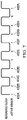
- FIG. 7 illustrates an example timing diagram of time-division multiplexed processing of multiple resistive-inductive-capacitive sensors 402 controlled by multiple processing ICs 412 E, in accordance with embodiments of the present disclosure.
- the timing diagram of FIG. 7 assumes the presence within resonant phase sensing system 112 E of only two processing ICs 412 E (e.g., processing ICs 412 E- 1 and 412 E- 2 ), with processing IC 412 E- 1 controlling sensors 402 A- 402 D and processing IC 412 E- 2 controlling sensors 402 E- 402 H.
- FIG. 7 illustrates an example timing diagram of time-division multiplexed processing of multiple resistive-inductive-capacitive sensors 402 controlled by multiple processing ICs 412 E, in accordance with embodiments of the present disclosure.
- the timing diagram of FIG. 7 assumes the presence within resonant phase sensing system 112 E of only two processing ICs 412 E (e.g., processing ICs
- master processing IC 412 E- 1 may generate the reference clock at its synchronization pin SYNC and slave processing IC 412 E- 2 may receive the reference clock via its synchronization pin SYNC.
- Each of processing IC 412 E- 1 and 412 E- 2 may configure a respective schedule and activate its respective sensors and perform measurements of its respective sensors based on such schedule and the reference clock. For example, as shown in FIG.
- processing IC 412 E- 1 may configure its respective schedule such that: (a) it activates and measures resistive-inductor-capacitive sensor 402 A in response to the first edge of the reference clock; (b) it activates and measures resistive-inductor-capacitive sensor 402 B in response to the second edge of the reference clock; (c) it activates and measures resistive-inductor-capacitive sensor 402 C in response to the third edge of the reference clock; and (d) it activates and measures resistive-inductor-capacitive sensor 402 D in response to the fourth edge of the reference clock.
- processing IC 412 E- 1 may further configure its respective schedule to include a fifth duration between the fifth and sixth edges of the reference clock to perform such operations.
- processing IC 412 E- 2 may configure its respective schedule such that: (a) it activates and measures resistive-inductor-capacitive sensor 402 E in response to the sixth edge of the reference clock; (b) it activates and measures resistive-inductor-capacitive sensor 402 F in response to the seventh edge of the reference clock; (c) it activates and measures resistive-inductor-capacitive sensor 402 G in response to the eighth edge of the reference clock; (d) it activates and measures resistive-inductor-capacitive sensor 402 H in response to the ninth edge of the reference clock; and (e) allocates after the tenth edge of the reference clock a duration for additional sensing activity.
- each processing IC 412 E may be configured to, after detecting 10 edges of the reference clock, reset a counter for counting edges of the reference clock.
- each processing IC 412 E may use its own internal oscillator with programmed times after a toggle of the reference clock in order to sequence activity of its respective resistive-inductive-capacitive sensors 402 .
- Such approach allows for minimal amount of activity on synchronization pin SYNC for each processing IC 412 E, but may require that the scheduled conversion times have a guard band sufficient to account for variations in clock frequency among individual processing ICs 412 E.
- the amount of time scheduled to a conversion time for a sensor should include sufficient time to account for variations in the internal clocks after sensing begins.
- a special symbol may be communicated by the master processing IC 412 E via its synchronization pin SYNC in order to provide synchronization in the case of a noisy environment in which bit errors may occasionally occur on the conductive traces coupling synchronization pins SYNC to one another.
- One example of such a special symbol may include an additional toggle of the reference clock in proximity to the roll-over toggle of the reference clock to indicate that roll-over has been reached and internal counters should be reset.
- processing ICs 412 E may be configured to distinguish this additional toggle of the reference clock from normal synchronization toggles by keeping track of a normal interval between toggles using their internal clocks and treating toggles close in time as the special symbol. Such technique may allow for counters of the processing ICs 412 E to align if alignment is lost.
- FIG. 8 illustrates a diagram of selected components of an example resonant phase sensing system 112 F implementing time-division multiplexed processing of multiple resistive-inductive-capacitive sensors 402 controlled by multiple processing integrated circuits 412 F, in accordance with embodiments of the present disclosure.
- Example resonant phase sensing system 112 F may be used to implement resonant phase sensing system 112 of FIG. 1 . As shown in FIG.
- resonant phase sensing system 112 F may include a plurality of processing ICs 412 F (e.g., processing ICs 412 F- 1 , 412 F- 2 , 412 F- 3 , and 412 F- 4 ), each processing IC 412 F communicatively coupled to a respective set of resistive-inductor-capacitive sensors 402 , thus enabling each processing IC 412 F to control its respective set of resistive-inductor-capacitive sensors 402 .
- FIG. 8 depicts resonant phase sensing system 112 F having four processing ICs 412 F and each processing IC 412 F having a respective set of four resistive-inductor-capacitive sensors 402 .
- resonant phase sensing system 112 F may have any suitable number of processing ICs 412 F and each processing IC 412 F may have a respective set with any suitable number of resistive-inductor-capacitive sensors 402 .
- Resonant phase sensing system 112 F of FIG. 8 may be, in many respects, similar to resonant phase sensing system 112 E of FIG. 6 . Accordingly, only certain differences between resonant phase sensing system 112 F and resonance phase sensing system 112 E may be described herein.
- One main difference between resonant phase sensing system 112 F and resonance phase sensing system 112 E is that in lieu of a processing IC 412 F generating the reference clock, an external timing source 800 may be present to generate the reference clock, and each processing IC 412 F may receive the reference clock from external timing source 800 .
- each processing IC 412 F may operate as a slave device and external timing source 800 may comprise the master device.
- phase sensing system 112 F it may be desirable to either: (a) control the start time of external timing source 800 to after schedule configuration by processing ICs 412 F; or (b) provide a mechanism for notifying all processing ICs 412 F to initiate their respective counters at the same time.
- a mechanism may include monitoring of another input/output signal by processing ICs 412 F or use of an input/output write to an address that all processing ICs monitor.
- FIGS. 4A-8 may be modified to implement an open-loop system for sensing of displacement.
- a processing IC may include no feedback path from amplitude and phase calculation block 431 to VCO 416 or variable phase shifter 419 and thus may also lack a feedback low-pass filter 434 .
- a phase measurement may still be made by comparing a change in phase to a reference phase value, but the oscillation frequency driven by VCO 416 may not be modified, or the phase shifted by variable phase shifter 419 may not be shifted.
- a resonant phase sensing system 112 may perform phase detection and/or otherwise determine phase information associated with resistive-inductive-capacitive sensor 402 in any suitable manner, including, without limitation, using only one of the incident path or quadrature path to determine phase information.
- an incident/quadrature detector as disclosed herein may include one or more frequency translation stages that translate the sensor signal into direct-current signal directly or into an intermediate frequency signal and then into a direct-current signal. Any of such frequency translation stages may be implemented either digitally after an analog-to-digital converter stage or in analog before an analog-to-digital converter stage.
- a coherent incident/quadrature detector as a phase detector for determining phase information associated with a resistive-inductive-capacitive sensor 402
- changes in a resistive-inductive-capacitive sensor 402 may be measured by operating such resistive-inductive-capacitive sensor 402 as an oscillator and measuring its frequency of oscillation and changes thereto.
- resistive-inductive-capacitive sensor 402 may operate based on a principle that any change in impedance based on displacement of mechanical member 105 may be used to sense displacement.
- displacement of mechanical member 105 may cause a change in a capacitance of resistive-inductive-capacitive sensor 402 , such as if mechanical member 105 included a metal plate implementing one of the capacitive plates of capacitor 406 .
- DSP 432 may be capable of processing phase information to make a binary determination of whether physical interaction associated with a human-machine interface associated with mechanical member 105 has occurred and/or ceased to occur
- DSP 432 may quantify a duration of a displacement of mechanical member 105 to more than one detection threshold, for example to detect different types of physical interactions (e.g., a short press of a virtual button versus a long press of the virtual button).
- DSP 432 may quantify a magnitude of the displacement to more than one detection threshold, for example to detect different types of physical interactions (e.g., a light press of a virtual button versus a quick and hard press of the virtual button).
- references in the appended claims to an apparatus or system or a component of an apparatus or system being adapted to, arranged to, capable of, configured to, enabled to, operable to, or operative to perform a particular function encompasses that apparatus, system, or component, whether or not it or that particular function is activated, turned on, or unlocked, as long as that apparatus, system, or component is so adapted, arranged, capable, configured, enabled, operable, or operative. Accordingly, modifications, additions, or omissions may be made to the systems, apparatuses, and methods described herein without departing from the scope of the disclosure. For example, the components of the systems and apparatuses may be integrated or separated.
- each refers to each member of a set or each member of a subset of a set.
Abstract
Description
Claims (21)
Priority Applications (1)
| Application Number | Priority Date | Filing Date | Title |
|---|---|---|---|
| US16/457,489 US11402946B2 (en) | 2019-02-26 | 2019-06-28 | Multi-chip synchronization in sensor applications |
Applications Claiming Priority (2)
| Application Number | Priority Date | Filing Date | Title |
|---|---|---|---|
| US201962810787P | 2019-02-26 | 2019-02-26 | |
| US16/457,489 US11402946B2 (en) | 2019-02-26 | 2019-06-28 | Multi-chip synchronization in sensor applications |
Publications (2)
| Publication Number | Publication Date |
|---|---|
| US20200272301A1 US20200272301A1 (en) | 2020-08-27 |
| US11402946B2 true US11402946B2 (en) | 2022-08-02 |
Family
ID=72141128
Family Applications (1)
| Application Number | Title | Priority Date | Filing Date |
|---|---|---|---|
| US16/457,489 Active 2039-09-08 US11402946B2 (en) | 2019-02-26 | 2019-06-28 | Multi-chip synchronization in sensor applications |
Country Status (1)
| Country | Link |
|---|---|
| US (1) | US11402946B2 (en) |
Families Citing this family (21)
| Publication number | Priority date | Publication date | Assignee | Title |
|---|---|---|---|---|
| US10921159B1 (en) | 2018-03-29 | 2021-02-16 | Cirrus Logic, Inc. | Use of reference sensor in resonant phase sensing system |
| US10908200B2 (en) | 2018-03-29 | 2021-02-02 | Cirrus Logic, Inc. | Resonant phase sensing of resistive-inductive-capacitive sensors |
| US10642435B2 (en) | 2018-03-29 | 2020-05-05 | Cirrus Logic, Inc. | False triggering prevention in a resonant phase sensing system |
| US10725549B2 (en) * | 2018-03-29 | 2020-07-28 | Cirrus Logic, Inc. | Efficient detection of human machine interface interaction using a resonant phase sensing system |
| US11092657B2 (en) | 2018-03-29 | 2021-08-17 | Cirrus Logic, Inc. | Compensation of changes in a resonant phase sensing system including a resistive-inductive-capacitive sensor |
| US11536758B2 (en) | 2019-02-26 | 2022-12-27 | Cirrus Logic, Inc. | Single-capacitor inductive sense systems |
| US11402946B2 (en) | 2019-02-26 | 2022-08-02 | Cirrus Logic, Inc. | Multi-chip synchronization in sensor applications |
| US10935620B2 (en) | 2019-02-26 | 2021-03-02 | Cirrus Logic, Inc. | On-chip resonance detection and transfer function mapping of resistive-inductive-capacitive sensors |
| US10948313B2 (en) | 2019-02-26 | 2021-03-16 | Cirrus Logic, Inc. | Spread spectrum sensor scanning using resistive-inductive-capacitive sensors |
| FR3097990B1 (en) * | 2019-06-27 | 2021-05-21 | Thales Sa | TOUCH SURFACE WITH HYBRID TOUCH DETECTION |
| US11079874B2 (en) | 2019-11-19 | 2021-08-03 | Cirrus Logic, Inc. | Virtual button characterization engine |
| US10908750B1 (en) | 2019-11-26 | 2021-02-02 | Synaptics Incorporated | Minimizing latency for resonant input object detection and classification |
| US11093078B1 (en) * | 2020-03-20 | 2021-08-17 | Cypress Semiconductor Corporation | Always on low power capacitive matrix autonomous scan |
| US11579030B2 (en) | 2020-06-18 | 2023-02-14 | Cirrus Logic, Inc. | Baseline estimation for sensor system |
| US11868540B2 (en) | 2020-06-25 | 2024-01-09 | Cirrus Logic Inc. | Determination of resonant frequency and quality factor for a sensor system |
| US11835410B2 (en) | 2020-06-25 | 2023-12-05 | Cirrus Logic Inc. | Determination of resonant frequency and quality factor for a sensor system |
| US11619519B2 (en) | 2021-02-08 | 2023-04-04 | Cirrus Logic, Inc. | Predictive sensor tracking optimization in multi-sensor sensing applications |
| US11821761B2 (en) | 2021-03-29 | 2023-11-21 | Cirrus Logic Inc. | Maximizing dynamic range in resonant sensing |
| US11808669B2 (en) | 2021-03-29 | 2023-11-07 | Cirrus Logic Inc. | Gain and mismatch calibration for a phase detector used in an inductive sensor |
| US11507199B2 (en) | 2021-03-30 | 2022-11-22 | Cirrus Logic, Inc. | Pseudo-differential phase measurement and quality factor compensation |
| US11854738B2 (en) | 2021-12-02 | 2023-12-26 | Cirrus Logic Inc. | Slew control for variable load pulse-width modulation driver and load sensing |
Citations (154)
| Publication number | Priority date | Publication date | Assignee | Title |
|---|---|---|---|---|
| US4268822A (en) | 1978-10-18 | 1981-05-19 | The Foxboro Company | Apparatus for determining the state of each of a plurality of bi-state devices |
| US4888554A (en) | 1988-08-02 | 1989-12-19 | Mcw Research Foundation, Inc. | Electron paramagnetic resonance (EPR) spectrometer |
| DE4004450A1 (en) | 1990-02-14 | 1991-08-29 | Heinrich Kissling Gmbh & Co Kg | Inductive proximity switch with variable oscillator supplying coil - uses tuned circuits in sensor and detector to avoid actuation from other metallic objects |
| US5286941A (en) | 1991-01-18 | 1994-02-15 | Thompson Tubes Electroniques | High frequency heating generator having an improved matching network between a tetrode amplifier and a resonant circuit |
| US5567920A (en) | 1992-03-02 | 1996-10-22 | Seiko Instruments Inc. | Position reading apparatus and key board apparatus |
| US5661269A (en) | 1994-02-03 | 1997-08-26 | Wacom Co., Ltd. | Position pointing device having resonant circuit with sequentially changed characteristics and combination thereof with position detecting device |
| US5898136A (en) | 1996-06-12 | 1999-04-27 | Wacom Co., Ltd. | Position detecting apparatus having a tablet and a position pointing device |
| WO2000033244A2 (en) | 1998-11-27 | 2000-06-08 | Synaptics (Uk) Limited | Position sensor |
| US6231520B1 (en) | 1998-06-02 | 2001-05-15 | Olympus Optical Co., Ltd. | Tactile sensor signal processing device capable of obtaining detailed living body information in short time |
| US20010045941A1 (en) | 1995-09-27 | 2001-11-29 | Louis B. Rosenberg | Force feedback system including multiple force processors |
| US6380923B1 (en) | 1993-08-31 | 2002-04-30 | Nippon Telegraph And Telephone Corporation | Full-time wearable information managing device and method for the same |
| US20030038624A1 (en) | 2001-06-29 | 2003-02-27 | Inductive Signature Technologies, Inc. | Inductive signature measurement circuit |
| GB2394295A (en) | 2002-10-16 | 2004-04-21 | Sensopad Technologies Ltd | Position sensing apparatus utilising signals induced in two resonators placed on a moving member |
| US20050192727A1 (en) | 1994-05-09 | 2005-09-01 | Automotive Technologies International Inc. | Sensor Assemblies |
| US20050258826A1 (en) | 2004-05-20 | 2005-11-24 | Mitsunari Kano | Displacement detection apparatus and displacement detection method |
| US20050283330A1 (en) | 2004-06-16 | 2005-12-22 | Laraia Jose M | Reactive sensor modules using pade' approximant based compensation and providing module-sourced excitation |
| US20060025897A1 (en) | 2004-07-30 | 2006-02-02 | Shostak Oleksandr T | Sensor assemblies |
| JP2006246289A (en) | 2005-03-07 | 2006-09-14 | Japan Aviation Electronics Industry Ltd | Detection apparatus |
| WO2006135483A2 (en) | 2005-06-10 | 2006-12-21 | Qsi Corporation | Sensor baseline compensation in a force-based touch device |
| US7173410B1 (en) | 2004-09-28 | 2007-02-06 | Rockwell Automation Technologies, Inc. | Proximity sensor combining impedance, frequency and decay constant information |
| EP1697710B1 (en) | 2003-11-29 | 2007-04-25 | TT Electronics Technology Limited | Inductive position sensing apparatus and method |
| WO2007068283A1 (en) | 2005-12-12 | 2007-06-21 | Semtech Neuchâtel SA | Sensor interface |
| US20070198926A1 (en) | 2004-02-23 | 2007-08-23 | Jazzmutant | Devices and methods of controlling manipulation of virtual objects on a multi-contact tactile screen |
| US20070268265A1 (en) | 2006-05-18 | 2007-11-22 | Cypress Semiconductor Corporation | Two-pin buttons |
| US20070296709A1 (en) | 2006-06-27 | 2007-12-27 | Cypress Semiconductor Corporation | Apparatus and method for detecting multiple buttons with one pin |
| US20070296593A1 (en) | 2006-06-27 | 2007-12-27 | Hall Stewart E | Resonant circuit tuning system with dynamic impedance matching |
| US20080007534A1 (en) | 2006-07-10 | 2008-01-10 | Cypress Semiconductor Corporation | Touch-sensor with shared capacitive sensors |
| US20080024456A1 (en) | 2006-07-31 | 2008-01-31 | Tao Peng | Grounded button for cap sense |
| US20080088595A1 (en) | 2006-10-12 | 2008-04-17 | Hua Liu | Interconnected two-substrate layer touchpad capacitive sensing device |
| US20080088594A1 (en) | 2006-10-12 | 2008-04-17 | Hua Liu | Two-substrate layer touchpad capacitive sensing device |
| US20080143681A1 (en) | 2006-12-18 | 2008-06-19 | Xiaoping Jiang | Circular slider with center button |
| US20080142352A1 (en) | 2006-12-18 | 2008-06-19 | Wright David G | Two circuit board touch-sensor device |
| US20080150905A1 (en) | 2006-12-21 | 2008-06-26 | Grivna Edward L | Feedback mechanism for user detection of reference location on a sensing device |
| US20080158185A1 (en) | 2007-01-03 | 2008-07-03 | Apple Inc. | Multi-Touch Input Discrimination |
| US20080312857A1 (en) | 2006-03-27 | 2008-12-18 | Seguine Dennis R | Input/output multiplexer bus |
| US20090009195A1 (en) | 2007-07-03 | 2009-01-08 | Cypress Semiconductor Corporation | Method for improving scan time and sensitivity in touch sensitive user interface device |
| US20090008161A1 (en) | 2007-07-04 | 2009-01-08 | Jones Christopher W | Capacitive sensor array and gesture recognition |
| US20090058430A1 (en) | 2007-09-05 | 2009-03-05 | Sentrinsic | Systems and Methods for Sensing Positions of Components |
| US20090140728A1 (en) * | 2007-11-29 | 2009-06-04 | Rollins George E | Apparatus and methods for proximity sensing circuitry |
| US20090278685A1 (en) | 2008-05-12 | 2009-11-12 | General Electric Company | Methods and systems for calibration of rfid sensors |
| US20090302868A1 (en) | 2005-12-29 | 2009-12-10 | Thomas Feucht | Analysis and Compensation Circuit for an Inductive Displacement Sensor |
| US20090308155A1 (en) | 2008-06-12 | 2009-12-17 | Honeywell International Inc. | Passive humidity sensors and methods for temperature adjusted humidity sensing |
| US20100045360A1 (en) | 2004-12-14 | 2010-02-25 | Mark Anthony Howard | Detector |
| US20100153845A1 (en) | 2008-12-16 | 2010-06-17 | Immersion Corporation | Haptic feedback generation based on resonant frequency |
| US20100211902A1 (en) | 2006-10-10 | 2010-08-19 | Promethean Limited | Interactive display system |
| US20100231239A1 (en) | 2007-10-18 | 2010-09-16 | Kiyoshi Tateishi | Capacitance detector |
| US20100238121A1 (en) | 2006-07-13 | 2010-09-23 | Eliot David Thomas Ely | Transducer |
| US20100328249A1 (en) | 2009-06-25 | 2010-12-30 | Stmicroelecronics Asia Pacific Pte Ltd. | Capacitive-inductive touch screen |
| US20110005090A1 (en) | 2008-04-11 | 2011-01-13 | Lee Fred S | Displacement sensing using a flexible substrate |
| US20110216311A1 (en) | 2010-03-02 | 2011-09-08 | Li-Cor, Inc. | Method and apparatus for locking a laser with a resonant cavity |
| US20110267302A1 (en) | 2009-01-21 | 2011-11-03 | Peter Fasshauer | Touch-detection system for display |
| US20110285667A1 (en) | 2010-05-21 | 2011-11-24 | Ivan Poupyrev | Electrovibration for touch surfaces |
| US20110291821A1 (en) | 2010-05-31 | 2011-12-01 | Samsung Electro-Mechanics Co., Ltd. | Haptic device |
| US20110301876A1 (en) | 2009-02-18 | 2011-12-08 | National University Corporation Kyoto Institute Of Technology | Tactile sensor unit, robot including the tactile sensor unit, and load calculation method |
| US8144126B2 (en) | 2007-05-07 | 2012-03-27 | Cypress Semiconductor Corporation | Reducing sleep current in a capacitance sensing system |
| US20130018489A1 (en) | 2011-07-14 | 2013-01-17 | Grunthaner Martin Paul | Combined force and proximity sensing |
| US8384378B2 (en) | 2009-02-27 | 2013-02-26 | Kimberly-Clark Worldwide, Inc. | Conductivity sensor |
| US20130076374A1 (en) | 2011-09-22 | 2013-03-28 | Li-Hsin Huang | Charged body sensing system |
| US8421446B2 (en) | 2006-06-07 | 2013-04-16 | Vogt Electronic Components Gmbh | Position encoder and a method for detecting the position of a movable part of a machine |
| US20130106756A1 (en) | 2010-06-30 | 2013-05-02 | Kyocera Corporation | Tactile sensation providing apparatus and control method for tactile sensation providing apparatus |
| US20130106769A1 (en) | 2011-10-28 | 2013-05-02 | Atmel Corporation | Capacitive and Inductive Sensing |
| KR20130052059A (en) | 2011-11-11 | 2013-05-22 | 국방과학연구소 | Temperature compensation method and temperature and oscillation control loop system of parallel plate electrode type resonance sensor |
| US20130269446A1 (en) | 2012-04-13 | 2013-10-17 | Wacom Co., Ltd. | Position indicator |
| US20140002113A1 (en) | 2012-05-22 | 2014-01-02 | Synaptics Incorporated | Force enhanced input device |
| EP2682843A1 (en) | 2009-07-17 | 2014-01-08 | Apple Inc. | Method and apparatus for localization of haptic feedback |
| US20140028327A1 (en) | 2012-07-26 | 2014-01-30 | General Electric Company | Method for sensor reader calibration |
| US8674950B2 (en) | 2007-09-06 | 2014-03-18 | Cypress Semiconductor Corporation | Dual-sensing-mode touch-sensor device |
| US20140225599A1 (en) | 2013-02-08 | 2014-08-14 | Hamilton Sundstrand Corporation | Transformer based sensor arrangement |
| US20140267065A1 (en) | 2013-03-14 | 2014-09-18 | Immersion Corporation | Contactor-based haptic feedback generation |
| US20150022174A1 (en) | 2013-07-17 | 2015-01-22 | Avatekh, Inc. | Method and apparatus for control of switched-mode power supplies |
| US8970230B2 (en) | 2011-02-28 | 2015-03-03 | Cypress Semiconductor Corporation | Capacitive sensing button on chip |
| US20150077094A1 (en) | 2013-09-16 | 2015-03-19 | Texas Instruments Incorporated | Inductive position sensing with single channel interface to multiple resonant sensors |
| US20150084874A1 (en) | 2013-09-26 | 2015-03-26 | Synaptics Incorporated | Methods and apparatus for click detection on a force pad using dynamic thresholds |
| US20150293695A1 (en) | 2012-11-15 | 2015-10-15 | Oliver SCHÖLEBEN | Method and Device for Typing on Mobile Computing Devices |
| US9164605B1 (en) | 2010-02-03 | 2015-10-20 | Cypress Semiconductor Corporation | Force sensor baseline calibration |
| US20150329199A1 (en) | 2013-12-18 | 2015-11-19 | Merlin Technology, Inc. | Control interface, system and method |
| US20160018940A1 (en) | 2014-07-18 | 2016-01-21 | Generalplus Technology Inc. | Method for increasing signal to noise ratio of capacitive touch device and capacitive touch device and touch panel using the same |
| US20160048256A1 (en) | 2005-11-28 | 2016-02-18 | Synaptics Incorporated | Methods and systems for implementing modal changes in a device in response to proximity and force indications |
| WO2016032704A1 (en) | 2014-08-25 | 2016-03-03 | 3M Innovative Properties Company | Capacitive-based touch apparatus and method with reduced interference |
| US20160117084A1 (en) | 2004-05-06 | 2016-04-28 | Apple Inc. | Operation of a computer with touch screen interface |
| US20160162031A1 (en) | 2012-05-09 | 2016-06-09 | Apple Inc. | Thresholds for Determining Feedback in Computing Devices |
| US20160179243A1 (en) | 2014-12-22 | 2016-06-23 | Synaptics Incorporated | Asynchronous interference detection in a capacitive sensing system |
| US20160231874A1 (en) | 2012-02-15 | 2016-08-11 | International Business Machines Corporation | Automatic Detection of User Preferences for Alternate User Interface Model |
| US20160252403A1 (en) | 2015-02-27 | 2016-09-01 | Jtekt Corporation | Temperature detection apparatus and rotation angle detection apparatus |
| US20160305997A1 (en) | 2015-04-20 | 2016-10-20 | Infineon Technologies Ag | System and Method for a Capacitive Sensor |
| US20160357296A1 (en) | 2015-06-03 | 2016-12-08 | Microsoft Technology Licensing, Llc | Force Sensing and Inadvertent Input Control |
| US20170023429A1 (en) | 2015-04-20 | 2017-01-26 | Infineon Technologies Ag | System and Method for a MEMS Sensor |
| DE102015215330A1 (en) | 2015-08-11 | 2017-02-16 | Continental Teves Ag & Co. Ohg | Inductive sensors with operating frequency near the resonance |
| DE102015215331A1 (en) | 2015-08-11 | 2017-02-16 | Continental Teves Ag & Co. Ohg | Electronic control unit |
| CN106471708A (en) | 2014-05-14 | 2017-03-01 | 日商速充股份有限公司 | wireless power transmission device |
| US20170077735A1 (en) | 2015-09-16 | 2017-03-16 | Energous Corporation | Systems and methods for transmitting power to receivers |
| US20170093222A1 (en) | 2014-06-19 | 2017-03-30 | Koninklijke Philips N.V. | Wireless inductive power transfer |
| US20170140644A1 (en) | 2015-11-12 | 2017-05-18 | Samsung Electronics Co., Ltd | Electronic device and method for performing operations according to proximity of external object |
| US20170147068A1 (en) | 2015-11-24 | 2017-05-25 | Lenovo (Singapore) Pte. Ltd. | Apparatus, method, and program product to reduce noise |
| US20170168578A1 (en) | 2015-12-15 | 2017-06-15 | Lenovo (Singapore) Pte. Ltd. | Keyboard |
| US20170187541A1 (en) | 2015-12-29 | 2017-06-29 | General Electric Company | Systems and methods for networked sensor nodes |
| US20170185173A1 (en) | 2014-10-06 | 2017-06-29 | Wacom Co., Ltd. | Position indicator |
| US9707502B1 (en) | 2016-09-26 | 2017-07-18 | 3M Innovative Properties Company | Conductive loop detection member |
| US20170237293A1 (en) | 2016-02-15 | 2017-08-17 | Motorola Solutions, Inc. | Systems and methods for controlling wireless power transfer |
| US20170282715A1 (en) | 2016-03-30 | 2017-10-05 | Honda Motor Co., Ltd. | System and method for controlling a vehicle display in a moving vehicle |
| US20170322643A1 (en) | 2015-01-29 | 2017-11-09 | Wacom Co., Ltd. | Electronic pen |
| US20170328740A1 (en) | 2012-07-13 | 2017-11-16 | Qualcomm Incorporated | Systems, methods, and apparatus for detection of metal objects in a predetermined space |
| US20170371380A1 (en) | 2016-06-22 | 2017-12-28 | Texas Instruments Incorporated | Securing a touch sensor assembly within a device |
| US20170371473A1 (en) | 2016-06-23 | 2017-12-28 | A D Metro | Touch Sensor Device and Method |
| US20170371381A1 (en) | 2016-06-23 | 2017-12-28 | Texas Instruments Incorporated | Securing a touch sensor assembly for a touch button within a device |
| US20180019722A1 (en) | 2016-07-15 | 2018-01-18 | Peregrine Semiconductor Corporation | Hybrid Coupler with Phase and Attenuation Control |
| US20180059793A1 (en) | 2016-08-31 | 2018-03-01 | Apple Inc. | Electronic device including multi-phase driven linear haptic actuator and related methods |
| US20180055448A1 (en) | 2015-03-26 | 2018-03-01 | Koninklijke Philips N.V. | Contact lens for analyzing ocular fluid |
| US20180067601A1 (en) | 2016-09-06 | 2018-03-08 | Apple Inc. | Thermal compensation for force-sensitive button |
| US20180088702A1 (en) | 2016-09-23 | 2018-03-29 | Apple Inc. | Pressure compensation for force-sensitive touch screen |
| US20180088064A1 (en) | 2016-09-29 | 2018-03-29 | General Electric Company | Systems and methods for sensing compounds in an environment |
| US20180135409A1 (en) | 2015-08-03 | 2018-05-17 | Halliburton Energy Services, Inc. | Electromagnetic Telemetry Using Capacitive Electrodes |
| US20180183372A1 (en) | 2015-12-31 | 2018-06-28 | Goertek Inc. | Tactile vibration control system and method for smart terminal |
| US20180182212A1 (en) | 2015-12-13 | 2018-06-28 | Goertek Inc. | Tactile vibration control system and method for smart terminal |
| US20180221796A1 (en) | 2015-08-14 | 2018-08-09 | 3M Innovative Properties Company | Electromagnetic sensor for active monitoring of filter media within a filtration system |
| US20180229161A1 (en) | 2015-08-14 | 2018-08-16 | 3M Innovative Properties Company | Electronic sensor having electrical contacts for direct monitoring of filter media within a filtration system |
| US20180231485A1 (en) | 2017-02-13 | 2018-08-16 | General Electric Company | Sensing system and method |
| US20180260050A1 (en) | 2017-03-10 | 2018-09-13 | Cypress Semiconductor Corporation | Combined inductive sensing and capacitive sensing |
| US20180321748A1 (en) | 2017-05-08 | 2018-11-08 | Cirrus Logic International Semiconductor Ltd. | Integrated haptic system |
| US20190179146A1 (en) | 2017-12-08 | 2019-06-13 | Facebook Technolgies, LLC | Selective tracking of a head-mounted display |
| US20190197218A1 (en) | 2017-12-22 | 2019-06-27 | Synaptics Incorporated | Systems and methods for behavioral authentication using a touch sensor device |
| US20190204929A1 (en) | 2017-12-29 | 2019-07-04 | Immersion Corporation | Devices and methods for dynamic association of user input with mobile device actions |
| CN209069345U (en) | 2018-12-24 | 2019-07-05 | 南宁职业技术学院 | Multi-parameters sampling circuit |
| US20190235629A1 (en) | 2018-01-29 | 2019-08-01 | Cirrus Logic International Semiconductor Ltd. | Vibro-haptic design and automatic evaluation of haptic stimuli |
| US10372328B2 (en) | 2012-01-09 | 2019-08-06 | Google Llc | Intelligent touchscreen keyboard with finger differentiation |
| US20190286263A1 (en) | 2017-08-08 | 2019-09-19 | Cambridge Touch Technologies Ltd. | Device for processing signals from a pressure-sensing touch panel |
| US20190302923A1 (en) | 2018-03-29 | 2019-10-03 | Cirrus Logic International Semiconductor Ltd. | False triggering prevention in a resonant phase sensing system |
| US20190302193A1 (en) | 2018-03-29 | 2019-10-03 | Cirrus Logic International Semiconductor Ltd. | Compensation of changes in a resonant phase sensing system including a resistive-inductive-capacitive sensor |
| US20190302922A1 (en) | 2018-03-29 | 2019-10-03 | Cirrus Logic International Semiconductor Ltd. | Q-factor enhancement in resonant phase sensing of resistive-inductive-capacitive sensors |
| US20190302890A1 (en) | 2018-03-29 | 2019-10-03 | Cirrus Logic International Semiconductor Ltd. | Efficient detection of human machine interface interaction using a resonant phase sensing system |
| US20190302161A1 (en) | 2018-03-29 | 2019-10-03 | Cirrus Logic International Semiconductor Ltd. | Resonant phase sensing of resistive-inductive-capacitive sensors |
| US20190326906A1 (en) | 2016-06-30 | 2019-10-24 | Schlumberger Technology Corporation | Shaft proximity sensors |
| US20190339313A1 (en) | 2018-05-04 | 2019-11-07 | Synaptics Incorporated | Using electrical resistance to estimate force on an electrode during temperature changes |
| GB2573644A (en) | 2018-03-29 | 2019-11-13 | Cirrus Logic Int Semiconductor Ltd | Resonant phase sensing of resistive-inductive-capacitive sensors |
| US20190377468A1 (en) | 2018-06-06 | 2019-12-12 | Cambridge Touch Technologies Ltd. | Pressure signal processing |
| US20200064160A1 (en) | 2018-08-22 | 2020-02-27 | Cirrus Logic International Semiconductor Ltd. | Detecting and adapting to changes in a resonant phase sensing system having a resistive-inductive-capacitive sensor |
| US20200064952A1 (en) | 2018-08-27 | 2020-02-27 | Apple Inc. | Force or Touch Sensing on a Mobile Device Using Capacitive or Pressure Sensing |
| US10624691B2 (en) | 2015-09-30 | 2020-04-21 | Ethicon Llc | Techniques for operating generator for digitally generating electrical signal waveforms and surgical instruments |
| US20200133455A1 (en) | 2018-10-26 | 2020-04-30 | Cirrus Logic International Semiconductor Ltd. | Force sensing system and method |
| US20200177290A1 (en) | 2018-11-30 | 2020-06-04 | Rohde & Schwarz Gmbh & Co. Kg | Wireless coexistence test system, method and computer program for testing wireless coexistence |
| US20200191761A1 (en) | 2017-06-13 | 2020-06-18 | General Electric Company | Sensing system and method |
| US20200271477A1 (en) | 2019-02-26 | 2020-08-27 | Cirrus Logic International Semiconductor Ltd. | Spread spectrum sensor scanning using resistive-inductive-capacitive sensors |
| US20200271745A1 (en) | 2019-02-26 | 2020-08-27 | Cirrus Logic International Semiconductor Ltd. | On-chip resonance detection and transfer function mapping of resistive-inductive-capacitive sensors |
| US20200272301A1 (en) | 2019-02-26 | 2020-08-27 | Cirrus Logic International Semiconductor Ltd. | Multi-chip synchronization in sensor applications |
| US20200271706A1 (en) | 2019-02-26 | 2020-08-27 | Cirrus Logic International Semiconductor Ltd. | Single-capacitor inductive sense systems |
| US20200319237A1 (en) | 2019-04-03 | 2020-10-08 | Cirrus Logic International Semiconductor Ltd. | Auto-centering of sensor frequency of a resonant sensor |
| US20200320966A1 (en) | 2017-12-20 | 2020-10-08 | Sonuus Limited | Keyboard sensor systems and methods |
| US20200373923A1 (en) | 2019-05-20 | 2020-11-26 | Cypress Semiconductor Corporation | High performance inductive sensing all digital phase locked loop |
| US20200382113A1 (en) | 2019-06-03 | 2020-12-03 | Cirrus Logic International Semiconductor Ltd. | Compensation for air gap changes and temperature changes in a resonant phase detector |
| US10921159B1 (en) | 2018-03-29 | 2021-02-16 | Cirrus Logic, Inc. | Use of reference sensor in resonant phase sensing system |
| US20210064137A1 (en) | 2019-08-30 | 2021-03-04 | Apple Inc. | Electronic device including sensor driven haptic actuator and related methods |
| US20210149538A1 (en) | 2019-11-19 | 2021-05-20 | Cirrus Logic International Semiconductor Ltd. | Virtual button characterization engine |
| US20210152174A1 (en) | 2019-11-19 | 2021-05-20 | Cirrus Logic International Semiconductor Ltd. | Baseline calculation for sensor system |
| US11294503B2 (en) | 2008-01-04 | 2022-04-05 | Apple Inc. | Sensor baseline offset adjustment for a subset of sensor output values |
-
2019
- 2019-06-28 US US16/457,489 patent/US11402946B2/en active Active
Patent Citations (171)
| Publication number | Priority date | Publication date | Assignee | Title |
|---|---|---|---|---|
| US4268822A (en) | 1978-10-18 | 1981-05-19 | The Foxboro Company | Apparatus for determining the state of each of a plurality of bi-state devices |
| US4888554A (en) | 1988-08-02 | 1989-12-19 | Mcw Research Foundation, Inc. | Electron paramagnetic resonance (EPR) spectrometer |
| DE4004450A1 (en) | 1990-02-14 | 1991-08-29 | Heinrich Kissling Gmbh & Co Kg | Inductive proximity switch with variable oscillator supplying coil - uses tuned circuits in sensor and detector to avoid actuation from other metallic objects |
| US5286941A (en) | 1991-01-18 | 1994-02-15 | Thompson Tubes Electroniques | High frequency heating generator having an improved matching network between a tetrode amplifier and a resonant circuit |
| US5567920A (en) | 1992-03-02 | 1996-10-22 | Seiko Instruments Inc. | Position reading apparatus and key board apparatus |
| US6380923B1 (en) | 1993-08-31 | 2002-04-30 | Nippon Telegraph And Telephone Corporation | Full-time wearable information managing device and method for the same |
| US5661269A (en) | 1994-02-03 | 1997-08-26 | Wacom Co., Ltd. | Position pointing device having resonant circuit with sequentially changed characteristics and combination thereof with position detecting device |
| US20050192727A1 (en) | 1994-05-09 | 2005-09-01 | Automotive Technologies International Inc. | Sensor Assemblies |
| US20010045941A1 (en) | 1995-09-27 | 2001-11-29 | Louis B. Rosenberg | Force feedback system including multiple force processors |
| US5898136A (en) | 1996-06-12 | 1999-04-27 | Wacom Co., Ltd. | Position detecting apparatus having a tablet and a position pointing device |
| US6231520B1 (en) | 1998-06-02 | 2001-05-15 | Olympus Optical Co., Ltd. | Tactile sensor signal processing device capable of obtaining detailed living body information in short time |
| WO2000033244A2 (en) | 1998-11-27 | 2000-06-08 | Synaptics (Uk) Limited | Position sensor |
| US20030038624A1 (en) | 2001-06-29 | 2003-02-27 | Inductive Signature Technologies, Inc. | Inductive signature measurement circuit |
| GB2394295A (en) | 2002-10-16 | 2004-04-21 | Sensopad Technologies Ltd | Position sensing apparatus utilising signals induced in two resonators placed on a moving member |
| EP1697710B1 (en) | 2003-11-29 | 2007-04-25 | TT Electronics Technology Limited | Inductive position sensing apparatus and method |
| US20070198926A1 (en) | 2004-02-23 | 2007-08-23 | Jazzmutant | Devices and methods of controlling manipulation of virtual objects on a multi-contact tactile screen |
| US20160117084A1 (en) | 2004-05-06 | 2016-04-28 | Apple Inc. | Operation of a computer with touch screen interface |
| US20050258826A1 (en) | 2004-05-20 | 2005-11-24 | Mitsunari Kano | Displacement detection apparatus and displacement detection method |
| US20050283330A1 (en) | 2004-06-16 | 2005-12-22 | Laraia Jose M | Reactive sensor modules using pade' approximant based compensation and providing module-sourced excitation |
| US20060025897A1 (en) | 2004-07-30 | 2006-02-02 | Shostak Oleksandr T | Sensor assemblies |
| US7173410B1 (en) | 2004-09-28 | 2007-02-06 | Rockwell Automation Technologies, Inc. | Proximity sensor combining impedance, frequency and decay constant information |
| US20100045360A1 (en) | 2004-12-14 | 2010-02-25 | Mark Anthony Howard | Detector |
| JP2006246289A (en) | 2005-03-07 | 2006-09-14 | Japan Aviation Electronics Industry Ltd | Detection apparatus |
| WO2006135483A2 (en) | 2005-06-10 | 2006-12-21 | Qsi Corporation | Sensor baseline compensation in a force-based touch device |
| US20060293864A1 (en) | 2005-06-10 | 2006-12-28 | Soss David A | Sensor baseline compensation in a force-based touch device |
| US20160048256A1 (en) | 2005-11-28 | 2016-02-18 | Synaptics Incorporated | Methods and systems for implementing modal changes in a device in response to proximity and force indications |
| WO2007068283A1 (en) | 2005-12-12 | 2007-06-21 | Semtech Neuchâtel SA | Sensor interface |
| US20090302868A1 (en) | 2005-12-29 | 2009-12-10 | Thomas Feucht | Analysis and Compensation Circuit for an Inductive Displacement Sensor |
| US20080312857A1 (en) | 2006-03-27 | 2008-12-18 | Seguine Dennis R | Input/output multiplexer bus |
| US20070268265A1 (en) | 2006-05-18 | 2007-11-22 | Cypress Semiconductor Corporation | Two-pin buttons |
| US8421446B2 (en) | 2006-06-07 | 2013-04-16 | Vogt Electronic Components Gmbh | Position encoder and a method for detecting the position of a movable part of a machine |
| US20070296709A1 (en) | 2006-06-27 | 2007-12-27 | Cypress Semiconductor Corporation | Apparatus and method for detecting multiple buttons with one pin |
| US20070296593A1 (en) | 2006-06-27 | 2007-12-27 | Hall Stewart E | Resonant circuit tuning system with dynamic impedance matching |
| US20080007534A1 (en) | 2006-07-10 | 2008-01-10 | Cypress Semiconductor Corporation | Touch-sensor with shared capacitive sensors |
| US20100238121A1 (en) | 2006-07-13 | 2010-09-23 | Eliot David Thomas Ely | Transducer |
| US20080024456A1 (en) | 2006-07-31 | 2008-01-31 | Tao Peng | Grounded button for cap sense |
| US20100211902A1 (en) | 2006-10-10 | 2010-08-19 | Promethean Limited | Interactive display system |
| US20080088594A1 (en) | 2006-10-12 | 2008-04-17 | Hua Liu | Two-substrate layer touchpad capacitive sensing device |
| US20080088595A1 (en) | 2006-10-12 | 2008-04-17 | Hua Liu | Interconnected two-substrate layer touchpad capacitive sensing device |
| US20080143681A1 (en) | 2006-12-18 | 2008-06-19 | Xiaoping Jiang | Circular slider with center button |
| US20080142352A1 (en) | 2006-12-18 | 2008-06-19 | Wright David G | Two circuit board touch-sensor device |
| US20080150905A1 (en) | 2006-12-21 | 2008-06-26 | Grivna Edward L | Feedback mechanism for user detection of reference location on a sensing device |
| US20080158185A1 (en) | 2007-01-03 | 2008-07-03 | Apple Inc. | Multi-Touch Input Discrimination |
| US8144126B2 (en) | 2007-05-07 | 2012-03-27 | Cypress Semiconductor Corporation | Reducing sleep current in a capacitance sensing system |
| US20090009195A1 (en) | 2007-07-03 | 2009-01-08 | Cypress Semiconductor Corporation | Method for improving scan time and sensitivity in touch sensitive user interface device |
| US20090008161A1 (en) | 2007-07-04 | 2009-01-08 | Jones Christopher W | Capacitive sensor array and gesture recognition |
| US20090058430A1 (en) | 2007-09-05 | 2009-03-05 | Sentrinsic | Systems and Methods for Sensing Positions of Components |
| US8674950B2 (en) | 2007-09-06 | 2014-03-18 | Cypress Semiconductor Corporation | Dual-sensing-mode touch-sensor device |
| US20100231239A1 (en) | 2007-10-18 | 2010-09-16 | Kiyoshi Tateishi | Capacitance detector |
| US20090140728A1 (en) * | 2007-11-29 | 2009-06-04 | Rollins George E | Apparatus and methods for proximity sensing circuitry |
| US11294503B2 (en) | 2008-01-04 | 2022-04-05 | Apple Inc. | Sensor baseline offset adjustment for a subset of sensor output values |
| US20110005090A1 (en) | 2008-04-11 | 2011-01-13 | Lee Fred S | Displacement sensing using a flexible substrate |
| US20090278685A1 (en) | 2008-05-12 | 2009-11-12 | General Electric Company | Methods and systems for calibration of rfid sensors |
| US20090308155A1 (en) | 2008-06-12 | 2009-12-17 | Honeywell International Inc. | Passive humidity sensors and methods for temperature adjusted humidity sensing |
| US20100153845A1 (en) | 2008-12-16 | 2010-06-17 | Immersion Corporation | Haptic feedback generation based on resonant frequency |
| US20110267302A1 (en) | 2009-01-21 | 2011-11-03 | Peter Fasshauer | Touch-detection system for display |
| US20110301876A1 (en) | 2009-02-18 | 2011-12-08 | National University Corporation Kyoto Institute Of Technology | Tactile sensor unit, robot including the tactile sensor unit, and load calculation method |
| US8384378B2 (en) | 2009-02-27 | 2013-02-26 | Kimberly-Clark Worldwide, Inc. | Conductivity sensor |
| US20100328249A1 (en) | 2009-06-25 | 2010-12-30 | Stmicroelecronics Asia Pacific Pte Ltd. | Capacitive-inductive touch screen |
| EP2682843A1 (en) | 2009-07-17 | 2014-01-08 | Apple Inc. | Method and apparatus for localization of haptic feedback |
| US9164605B1 (en) | 2010-02-03 | 2015-10-20 | Cypress Semiconductor Corporation | Force sensor baseline calibration |
| US20110216311A1 (en) | 2010-03-02 | 2011-09-08 | Li-Cor, Inc. | Method and apparatus for locking a laser with a resonant cavity |
| US20110285667A1 (en) | 2010-05-21 | 2011-11-24 | Ivan Poupyrev | Electrovibration for touch surfaces |
| US20110291821A1 (en) | 2010-05-31 | 2011-12-01 | Samsung Electro-Mechanics Co., Ltd. | Haptic device |
| US20130106756A1 (en) | 2010-06-30 | 2013-05-02 | Kyocera Corporation | Tactile sensation providing apparatus and control method for tactile sensation providing apparatus |
| US8970230B2 (en) | 2011-02-28 | 2015-03-03 | Cypress Semiconductor Corporation | Capacitive sensing button on chip |
| US20130018489A1 (en) | 2011-07-14 | 2013-01-17 | Grunthaner Martin Paul | Combined force and proximity sensing |
| US20130076374A1 (en) | 2011-09-22 | 2013-03-28 | Li-Hsin Huang | Charged body sensing system |
| US20130106769A1 (en) | 2011-10-28 | 2013-05-02 | Atmel Corporation | Capacitive and Inductive Sensing |
| KR20130052059A (en) | 2011-11-11 | 2013-05-22 | 국방과학연구소 | Temperature compensation method and temperature and oscillation control loop system of parallel plate electrode type resonance sensor |
| US10372328B2 (en) | 2012-01-09 | 2019-08-06 | Google Llc | Intelligent touchscreen keyboard with finger differentiation |
| US20160231874A1 (en) | 2012-02-15 | 2016-08-11 | International Business Machines Corporation | Automatic Detection of User Preferences for Alternate User Interface Model |
| US10168855B2 (en) | 2012-02-15 | 2019-01-01 | International Business Machines Corporation | Automatic detection of user preferences for alternate user interface model |
| US20130269446A1 (en) | 2012-04-13 | 2013-10-17 | Wacom Co., Ltd. | Position indicator |
| US20160162031A1 (en) | 2012-05-09 | 2016-06-09 | Apple Inc. | Thresholds for Determining Feedback in Computing Devices |
| US20140002113A1 (en) | 2012-05-22 | 2014-01-02 | Synaptics Incorporated | Force enhanced input device |
| US20170328740A1 (en) | 2012-07-13 | 2017-11-16 | Qualcomm Incorporated | Systems, methods, and apparatus for detection of metal objects in a predetermined space |
| US20140028327A1 (en) | 2012-07-26 | 2014-01-30 | General Electric Company | Method for sensor reader calibration |
| US20150293695A1 (en) | 2012-11-15 | 2015-10-15 | Oliver SCHÖLEBEN | Method and Device for Typing on Mobile Computing Devices |
| US20140225599A1 (en) | 2013-02-08 | 2014-08-14 | Hamilton Sundstrand Corporation | Transformer based sensor arrangement |
| US20140267065A1 (en) | 2013-03-14 | 2014-09-18 | Immersion Corporation | Contactor-based haptic feedback generation |
| US20150022174A1 (en) | 2013-07-17 | 2015-01-22 | Avatekh, Inc. | Method and apparatus for control of switched-mode power supplies |
| CN105452884A (en) | 2013-09-16 | 2016-03-30 | 德州仪器公司 | Inductive position sensing with single channel interface to multiple resonant sensors |
| US20150077094A1 (en) | 2013-09-16 | 2015-03-19 | Texas Instruments Incorporated | Inductive position sensing with single channel interface to multiple resonant sensors |
| US20150084874A1 (en) | 2013-09-26 | 2015-03-26 | Synaptics Incorporated | Methods and apparatus for click detection on a force pad using dynamic thresholds |
| US20150329199A1 (en) | 2013-12-18 | 2015-11-19 | Merlin Technology, Inc. | Control interface, system and method |
| CN106471708A (en) | 2014-05-14 | 2017-03-01 | 日商速充股份有限公司 | wireless power transmission device |
| US20170093222A1 (en) | 2014-06-19 | 2017-03-30 | Koninklijke Philips N.V. | Wireless inductive power transfer |
| US20160018940A1 (en) | 2014-07-18 | 2016-01-21 | Generalplus Technology Inc. | Method for increasing signal to noise ratio of capacitive touch device and capacitive touch device and touch panel using the same |
| WO2016032704A1 (en) | 2014-08-25 | 2016-03-03 | 3M Innovative Properties Company | Capacitive-based touch apparatus and method with reduced interference |
| US20170185173A1 (en) | 2014-10-06 | 2017-06-29 | Wacom Co., Ltd. | Position indicator |
| US20160179243A1 (en) | 2014-12-22 | 2016-06-23 | Synaptics Incorporated | Asynchronous interference detection in a capacitive sensing system |
| US20170322643A1 (en) | 2015-01-29 | 2017-11-09 | Wacom Co., Ltd. | Electronic pen |
| US20160252403A1 (en) | 2015-02-27 | 2016-09-01 | Jtekt Corporation | Temperature detection apparatus and rotation angle detection apparatus |
| US20180055448A1 (en) | 2015-03-26 | 2018-03-01 | Koninklijke Philips N.V. | Contact lens for analyzing ocular fluid |
| US20160305997A1 (en) | 2015-04-20 | 2016-10-20 | Infineon Technologies Ag | System and Method for a Capacitive Sensor |
| US20170023429A1 (en) | 2015-04-20 | 2017-01-26 | Infineon Technologies Ag | System and Method for a MEMS Sensor |
| US20160357296A1 (en) | 2015-06-03 | 2016-12-08 | Microsoft Technology Licensing, Llc | Force Sensing and Inadvertent Input Control |
| US20180135409A1 (en) | 2015-08-03 | 2018-05-17 | Halliburton Energy Services, Inc. | Electromagnetic Telemetry Using Capacitive Electrodes |
| US10571307B2 (en) | 2015-08-11 | 2020-02-25 | Continental Teves Ag & Co. Ohg | Electronic control device |
| DE102015215330A1 (en) | 2015-08-11 | 2017-02-16 | Continental Teves Ag & Co. Ohg | Inductive sensors with operating frequency near the resonance |
| US20180195881A1 (en) | 2015-08-11 | 2018-07-12 | Continental Teves Ag & Co. Ohg | Electronic control device |
| DE102015215331A1 (en) | 2015-08-11 | 2017-02-16 | Continental Teves Ag & Co. Ohg | Electronic control unit |
| US20180221796A1 (en) | 2015-08-14 | 2018-08-09 | 3M Innovative Properties Company | Electromagnetic sensor for active monitoring of filter media within a filtration system |
| US20180229161A1 (en) | 2015-08-14 | 2018-08-16 | 3M Innovative Properties Company | Electronic sensor having electrical contacts for direct monitoring of filter media within a filtration system |
| US20170077735A1 (en) | 2015-09-16 | 2017-03-16 | Energous Corporation | Systems and methods for transmitting power to receivers |
| US10624691B2 (en) | 2015-09-30 | 2020-04-21 | Ethicon Llc | Techniques for operating generator for digitally generating electrical signal waveforms and surgical instruments |
| US20170140644A1 (en) | 2015-11-12 | 2017-05-18 | Samsung Electronics Co., Ltd | Electronic device and method for performing operations according to proximity of external object |
| US10726715B2 (en) | 2015-11-12 | 2020-07-28 | Samsung Electronics Co., Ltd. | Electronic device and method for performing operations according to proximity of external object |
| US20170147068A1 (en) | 2015-11-24 | 2017-05-25 | Lenovo (Singapore) Pte. Ltd. | Apparatus, method, and program product to reduce noise |
| US20180182212A1 (en) | 2015-12-13 | 2018-06-28 | Goertek Inc. | Tactile vibration control system and method for smart terminal |
| US20170168578A1 (en) | 2015-12-15 | 2017-06-15 | Lenovo (Singapore) Pte. Ltd. | Keyboard |
| US20170187541A1 (en) | 2015-12-29 | 2017-06-29 | General Electric Company | Systems and methods for networked sensor nodes |
| US20180183372A1 (en) | 2015-12-31 | 2018-06-28 | Goertek Inc. | Tactile vibration control system and method for smart terminal |
| US20170237293A1 (en) | 2016-02-15 | 2017-08-17 | Motorola Solutions, Inc. | Systems and methods for controlling wireless power transfer |
| US20170282715A1 (en) | 2016-03-30 | 2017-10-05 | Honda Motor Co., Ltd. | System and method for controlling a vehicle display in a moving vehicle |
| US20170371380A1 (en) | 2016-06-22 | 2017-12-28 | Texas Instruments Incorporated | Securing a touch sensor assembly within a device |
| US20170371381A1 (en) | 2016-06-23 | 2017-12-28 | Texas Instruments Incorporated | Securing a touch sensor assembly for a touch button within a device |
| US20170371473A1 (en) | 2016-06-23 | 2017-12-28 | A D Metro | Touch Sensor Device and Method |
| US20190326906A1 (en) | 2016-06-30 | 2019-10-24 | Schlumberger Technology Corporation | Shaft proximity sensors |
| US20180019722A1 (en) | 2016-07-15 | 2018-01-18 | Peregrine Semiconductor Corporation | Hybrid Coupler with Phase and Attenuation Control |
| US20180059793A1 (en) | 2016-08-31 | 2018-03-01 | Apple Inc. | Electronic device including multi-phase driven linear haptic actuator and related methods |
| US20180067601A1 (en) | 2016-09-06 | 2018-03-08 | Apple Inc. | Thermal compensation for force-sensitive button |
| US20180088702A1 (en) | 2016-09-23 | 2018-03-29 | Apple Inc. | Pressure compensation for force-sensitive touch screen |
| US9707502B1 (en) | 2016-09-26 | 2017-07-18 | 3M Innovative Properties Company | Conductive loop detection member |
| US20180088064A1 (en) | 2016-09-29 | 2018-03-29 | General Electric Company | Systems and methods for sensing compounds in an environment |
| US20180231485A1 (en) | 2017-02-13 | 2018-08-16 | General Electric Company | Sensing system and method |
| US20180260049A1 (en) | 2017-03-10 | 2018-09-13 | Cypress Semiconductor Corporation | Capacitance sensing and inductance sensing in different modes |
| US20180260050A1 (en) | 2017-03-10 | 2018-09-13 | Cypress Semiconductor Corporation | Combined inductive sensing and capacitive sensing |
| US20180321748A1 (en) | 2017-05-08 | 2018-11-08 | Cirrus Logic International Semiconductor Ltd. | Integrated haptic system |
| US20200191761A1 (en) | 2017-06-13 | 2020-06-18 | General Electric Company | Sensing system and method |
| US20190286263A1 (en) | 2017-08-08 | 2019-09-19 | Cambridge Touch Technologies Ltd. | Device for processing signals from a pressure-sensing touch panel |
| US20190179146A1 (en) | 2017-12-08 | 2019-06-13 | Facebook Technolgies, LLC | Selective tracking of a head-mounted display |
| US20200320966A1 (en) | 2017-12-20 | 2020-10-08 | Sonuus Limited | Keyboard sensor systems and methods |
| US20190197218A1 (en) | 2017-12-22 | 2019-06-27 | Synaptics Incorporated | Systems and methods for behavioral authentication using a touch sensor device |
| US20190204929A1 (en) | 2017-12-29 | 2019-07-04 | Immersion Corporation | Devices and methods for dynamic association of user input with mobile device actions |
| US20190235629A1 (en) | 2018-01-29 | 2019-08-01 | Cirrus Logic International Semiconductor Ltd. | Vibro-haptic design and automatic evaluation of haptic stimuli |
| US20190302923A1 (en) | 2018-03-29 | 2019-10-03 | Cirrus Logic International Semiconductor Ltd. | False triggering prevention in a resonant phase sensing system |
| GB2573644A (en) | 2018-03-29 | 2019-11-13 | Cirrus Logic Int Semiconductor Ltd | Resonant phase sensing of resistive-inductive-capacitive sensors |
| US20190302193A1 (en) | 2018-03-29 | 2019-10-03 | Cirrus Logic International Semiconductor Ltd. | Compensation of changes in a resonant phase sensing system including a resistive-inductive-capacitive sensor |
| US20190302161A1 (en) | 2018-03-29 | 2019-10-03 | Cirrus Logic International Semiconductor Ltd. | Resonant phase sensing of resistive-inductive-capacitive sensors |
| US10942610B2 (en) | 2018-03-29 | 2021-03-09 | Cirrus Logic, Inc. | False triggering prevention in a resonant phase sensing system |
| US10921159B1 (en) | 2018-03-29 | 2021-02-16 | Cirrus Logic, Inc. | Use of reference sensor in resonant phase sensing system |
| US10642435B2 (en) | 2018-03-29 | 2020-05-05 | Cirrus Logic, Inc. | False triggering prevention in a resonant phase sensing system |
| US10908200B2 (en) | 2018-03-29 | 2021-02-02 | Cirrus Logic, Inc. | Resonant phase sensing of resistive-inductive-capacitive sensors |
| US20190302890A1 (en) | 2018-03-29 | 2019-10-03 | Cirrus Logic International Semiconductor Ltd. | Efficient detection of human machine interface interaction using a resonant phase sensing system |
| US10725549B2 (en) | 2018-03-29 | 2020-07-28 | Cirrus Logic, Inc. | Efficient detection of human machine interface interaction using a resonant phase sensing system |
| US20190302922A1 (en) | 2018-03-29 | 2019-10-03 | Cirrus Logic International Semiconductor Ltd. | Q-factor enhancement in resonant phase sensing of resistive-inductive-capacitive sensors |
| US20190339313A1 (en) | 2018-05-04 | 2019-11-07 | Synaptics Incorporated | Using electrical resistance to estimate force on an electrode during temperature changes |
| US20190377468A1 (en) | 2018-06-06 | 2019-12-12 | Cambridge Touch Technologies Ltd. | Pressure signal processing |
| US20200064160A1 (en) | 2018-08-22 | 2020-02-27 | Cirrus Logic International Semiconductor Ltd. | Detecting and adapting to changes in a resonant phase sensing system having a resistive-inductive-capacitive sensor |
| US20200064952A1 (en) | 2018-08-27 | 2020-02-27 | Apple Inc. | Force or Touch Sensing on a Mobile Device Using Capacitive or Pressure Sensing |
| US20200133455A1 (en) | 2018-10-26 | 2020-04-30 | Cirrus Logic International Semiconductor Ltd. | Force sensing system and method |
| US20200177290A1 (en) | 2018-11-30 | 2020-06-04 | Rohde & Schwarz Gmbh & Co. Kg | Wireless coexistence test system, method and computer program for testing wireless coexistence |
| CN209069345U (en) | 2018-12-24 | 2019-07-05 | 南宁职业技术学院 | Multi-parameters sampling circuit |
| US20200272301A1 (en) | 2019-02-26 | 2020-08-27 | Cirrus Logic International Semiconductor Ltd. | Multi-chip synchronization in sensor applications |
| US20200271706A1 (en) | 2019-02-26 | 2020-08-27 | Cirrus Logic International Semiconductor Ltd. | Single-capacitor inductive sense systems |
| US20200271477A1 (en) | 2019-02-26 | 2020-08-27 | Cirrus Logic International Semiconductor Ltd. | Spread spectrum sensor scanning using resistive-inductive-capacitive sensors |
| US20210140797A1 (en) | 2019-02-26 | 2021-05-13 | Cirrus Logic International Semiconductor Ltd. | Spread spectrum sensor scanning using resistive-inductive-capacitive sensors |
| US10948313B2 (en) | 2019-02-26 | 2021-03-16 | Cirrus Logic, Inc. | Spread spectrum sensor scanning using resistive-inductive-capacitive sensors |
| US10935620B2 (en) | 2019-02-26 | 2021-03-02 | Cirrus Logic, Inc. | On-chip resonance detection and transfer function mapping of resistive-inductive-capacitive sensors |
| US20200271745A1 (en) | 2019-02-26 | 2020-08-27 | Cirrus Logic International Semiconductor Ltd. | On-chip resonance detection and transfer function mapping of resistive-inductive-capacitive sensors |
| US20200319237A1 (en) | 2019-04-03 | 2020-10-08 | Cirrus Logic International Semiconductor Ltd. | Auto-centering of sensor frequency of a resonant sensor |
| US20200373923A1 (en) | 2019-05-20 | 2020-11-26 | Cypress Semiconductor Corporation | High performance inductive sensing all digital phase locked loop |
| US20200382113A1 (en) | 2019-06-03 | 2020-12-03 | Cirrus Logic International Semiconductor Ltd. | Compensation for air gap changes and temperature changes in a resonant phase detector |
| US20210064137A1 (en) | 2019-08-30 | 2021-03-04 | Apple Inc. | Electronic device including sensor driven haptic actuator and related methods |
| US20210152174A1 (en) | 2019-11-19 | 2021-05-20 | Cirrus Logic International Semiconductor Ltd. | Baseline calculation for sensor system |
| WO2021101723A1 (en) | 2019-11-19 | 2021-05-27 | Cirrus Logic International Semiconductor Ltd. | System and method for determining a valid human interaction with a virtual button |
| WO2021101722A1 (en) | 2019-11-19 | 2021-05-27 | Cirrus Logic International Semiconductor Ltd. | Baseline calculation for sensor system |
| US11079874B2 (en) | 2019-11-19 | 2021-08-03 | Cirrus Logic, Inc. | Virtual button characterization engine |
| US20210149538A1 (en) | 2019-11-19 | 2021-05-20 | Cirrus Logic International Semiconductor Ltd. | Virtual button characterization engine |
Non-Patent Citations (19)
| Title |
|---|
| Combined Search and Examination Report under Sections 17 and 18(3), UKIPO, Application No. GB2001341.3, dated Jun. 29, 2020. |
| Combined Search and Examination Report under Sections 17 and 18(3), UKIPO, Application No. GB2111666.0, dated Feb. 11, 2022. |
| Combined Search and Examination Report, UKIPO, Application No. GB1904250.6, dated Sep. 10, 2019. |
| Definition of "control circuit", The New IEEE Standard Dictionary of Electrical and Electronics Terms, 5th Ed., p. 256 (1993). |
| Examination Report under Section 18(3), UKIPO, Application No. GB2015439.9, dated May 10, 2022. |
| Examination Report under Section 18(3), UKIPO, Application No. GB2101804.9, dated Feb. 25, 2022. |
| First Office Action, China National Intellectual Property Administration, Application No. 201980022689.9, dated Jun. 2, 2021. |
| First Office Action, China National Intellectual Property Administration, Application No. 201980022693.5, dated Jul. 8, 2021. |
| International Search Report and Written Opinion of the International Searching Authority, International Application No. PCT/US2019/021838, dated May 27, 2019. |
| International Search Report and Written Opinion of the International Searching Authority, International Application No. PCT/US2019/022518, dated May 24, 2019. |
| International Search Report and Written Opinion of the International Searching Authority, International Application No. PCT/US2019/022578, dated May 27, 2019. |
| International Search Report and Written Opinion of the International Searching Authority, International Application No. PCT/US2019/045554, dated Oct. 17, 2019. |
| International Search Report and Written Opinion of the International Searching Authority, International Application No. PCT/US2020/059101, dated Mar. 9, 2021. |
| International Search Report and Written Opinion of the International Searching Authority, International Application No. PCT/US2020/059113, dated Feb. 23, 2021. |
| International Search Report and Written Opinion of the International Searching Authority, International Application No. PCT/US2021/035695, dated Sep. 9, 2021. |
| International Search Report and Written Opinion of the International Searching Authority, International Application No. PCT/US2022/012721, dated Apr. 26, 2022. |
| International Search Report and Written Opinion of the International Searching Authority, International Application No. PCT/US2022/018886, dated Jun. 10, 2022. |
| Second Office Action, China National Intellectual Property Administration, Application No. 201980022693.5, dated Apr. 13, 2022. |
| Second Office Action, China National Intellectual Property Administration, Application No. 201980022693.5, dated Dec. 14, 2021. |
Also Published As
| Publication number | Publication date |
|---|---|
| US20200272301A1 (en) | 2020-08-27 |
Similar Documents
| Publication | Publication Date | Title |
|---|---|---|
| US11402946B2 (en) | Multi-chip synchronization in sensor applications | |
| US11836290B2 (en) | Spread spectrum sensor scanning using resistive-inductive-capacitive sensors | |
| US11714113B2 (en) | Auto-centering of sensor frequency of a resonant sensor | |
| US10908200B2 (en) | Resonant phase sensing of resistive-inductive-capacitive sensors | |
| CN111610922B (en) | On-chip resonance detection and transfer function mapping for resistive-inductive-capacitive sensors | |
| US11204670B2 (en) | False triggering prevention in a resonant phase sensing system | |
| US11536758B2 (en) | Single-capacitor inductive sense systems | |
| US20200064160A1 (en) | Detecting and adapting to changes in a resonant phase sensing system having a resistive-inductive-capacitive sensor | |
| US20190302922A1 (en) | Q-factor enhancement in resonant phase sensing of resistive-inductive-capacitive sensors | |
| GB2573644A (en) | Resonant phase sensing of resistive-inductive-capacitive sensors | |
| US11821761B2 (en) | Maximizing dynamic range in resonant sensing | |
| US11255892B2 (en) | Phase compensation in a resonant phase detector | |
| CN111949120B (en) | Interference detection and mitigation in inductive sensor applications and dynamic adaptation based on real-time noise detection | |
| US11507199B2 (en) | Pseudo-differential phase measurement and quality factor compensation | |
| GB2582065A (en) | On-chip resonance detection and transfer function mapping of resistive-inductive-capacitive sensors | |
| US11619519B2 (en) | Predictive sensor tracking optimization in multi-sensor sensing applications |
Legal Events
| Date | Code | Title | Description |
|---|---|---|---|
| AS | Assignment |
Owner name: CIRRUS LOGIC INTERNATIONAL SEMICONDUCTOR LTD., UNITED KINGDOM Free format text: ASSIGNMENT OF ASSIGNORS INTEREST;ASSIGNORS:DUEWER, BRUCE E.;KOST, MICHAEL A.;BEARDSWORTH, MATTHEW;AND OTHERS;SIGNING DATES FROM 20190318 TO 20190325;REEL/FRAME:049627/0865 |
|
| FEPP | Fee payment procedure |
Free format text: ENTITY STATUS SET TO UNDISCOUNTED (ORIGINAL EVENT CODE: BIG.); ENTITY STATUS OF PATENT OWNER: LARGE ENTITY |
|
| STPP | Information on status: patent application and granting procedure in general |
Free format text: RESPONSE TO NON-FINAL OFFICE ACTION ENTERED AND FORWARDED TO EXAMINER |
|
| STPP | Information on status: patent application and granting procedure in general |
Free format text: FINAL REJECTION MAILED |
|
| STPP | Information on status: patent application and granting procedure in general |
Free format text: RESPONSE AFTER FINAL ACTION FORWARDED TO EXAMINER |
|
| STPP | Information on status: patent application and granting procedure in general |
Free format text: ADVISORY ACTION MAILED |
|
| STCV | Information on status: appeal procedure |
Free format text: NOTICE OF APPEAL FILED |
|
| STPP | Information on status: patent application and granting procedure in general |
Free format text: RESPONSE TO NON-FINAL OFFICE ACTION ENTERED AND FORWARDED TO EXAMINER |
|
| STPP | Information on status: patent application and granting procedure in general |
Free format text: NON FINAL ACTION MAILED |
|
| STPP | Information on status: patent application and granting procedure in general |
Free format text: RESPONSE TO NON-FINAL OFFICE ACTION ENTERED AND FORWARDED TO EXAMINER |
|
| AS | Assignment |
Owner name: CIRRUS LOGIC, INC., TEXAS Free format text: ASSIGNMENT OF ASSIGNORS INTEREST;ASSIGNOR:CIRRUS LOGIC INTERNATIONAL SEMICONDUCTOR LTD.;REEL/FRAME:059032/0405 Effective date: 20150407 |
|
| STPP | Information on status: patent application and granting procedure in general |
Free format text: NOTICE OF ALLOWANCE MAILED -- APPLICATION RECEIVED IN OFFICE OF PUBLICATIONS |
|
| STPP | Information on status: patent application and granting procedure in general |
Free format text: AWAITING TC RESP., ISSUE FEE NOT PAID |
|
| STPP | Information on status: patent application and granting procedure in general |
Free format text: NOTICE OF ALLOWANCE MAILED -- APPLICATION RECEIVED IN OFFICE OF PUBLICATIONS |
|
| STPP | Information on status: patent application and granting procedure in general |
Free format text: PUBLICATIONS -- ISSUE FEE PAYMENT RECEIVED |
|
| STPP | Information on status: patent application and granting procedure in general |
Free format text: PUBLICATIONS -- ISSUE FEE PAYMENT VERIFIED |
|
| STCF | Information on status: patent grant |
Free format text: PATENTED CASE |
|
| STPP | Information on status: patent application and granting procedure in general |
Free format text: AWAITING TC RESP., ISSUE FEE NOT PAID |
|
| STCF | Information on status: patent grant |
Free format text: PATENTED CASE |