US11401774B2 - Seal arrangement - Google Patents
Seal arrangement Download PDFInfo
- Publication number
- US11401774B2 US11401774B2 US15/127,518 US201515127518A US11401774B2 US 11401774 B2 US11401774 B2 US 11401774B2 US 201515127518 A US201515127518 A US 201515127518A US 11401774 B2 US11401774 B2 US 11401774B2
- Authority
- US
- United States
- Prior art keywords
- seal arrangement
- sealing
- sealing element
- sealing elements
- arrangement
- Prior art date
- Legal status (The legal status is an assumption and is not a legal conclusion. Google has not performed a legal analysis and makes no representation as to the accuracy of the status listed.)
- Active, expires
Links
Images


Classifications
-
- E—FIXED CONSTRUCTIONS
- E21—EARTH OR ROCK DRILLING; MINING
- E21B—EARTH OR ROCK DRILLING; OBTAINING OIL, GAS, WATER, SOLUBLE OR MELTABLE MATERIALS OR A SLURRY OF MINERALS FROM WELLS
- E21B33/00—Sealing or packing boreholes or wells
- E21B33/10—Sealing or packing boreholes or wells in the borehole
- E21B33/12—Packers; Plugs
- E21B33/128—Packers; Plugs with a member expanded radially by axial pressure
-
- E—FIXED CONSTRUCTIONS
- E21—EARTH OR ROCK DRILLING; MINING
- E21B—EARTH OR ROCK DRILLING; OBTAINING OIL, GAS, WATER, SOLUBLE OR MELTABLE MATERIALS OR A SLURRY OF MINERALS FROM WELLS
- E21B23/00—Apparatus for displacing, setting, locking, releasing or removing tools, packers or the like in boreholes or wells
- E21B23/01—Apparatus for displacing, setting, locking, releasing or removing tools, packers or the like in boreholes or wells for anchoring the tools or the like
-
- E—FIXED CONSTRUCTIONS
- E21—EARTH OR ROCK DRILLING; MINING
- E21B—EARTH OR ROCK DRILLING; OBTAINING OIL, GAS, WATER, SOLUBLE OR MELTABLE MATERIALS OR A SLURRY OF MINERALS FROM WELLS
- E21B33/00—Sealing or packing boreholes or wells
- E21B33/10—Sealing or packing boreholes or wells in the borehole
- E21B33/12—Packers; Plugs
- E21B33/129—Packers; Plugs with mechanical slips for hooking into the casing
-
- E—FIXED CONSTRUCTIONS
- E21—EARTH OR ROCK DRILLING; MINING
- E21B—EARTH OR ROCK DRILLING; OBTAINING OIL, GAS, WATER, SOLUBLE OR MELTABLE MATERIALS OR A SLURRY OF MINERALS FROM WELLS
- E21B33/00—Sealing or packing boreholes or wells
- E21B33/10—Sealing or packing boreholes or wells in the borehole
- E21B33/12—Packers; Plugs
- E21B33/1208—Packers; Plugs characterised by the construction of the sealing or packing means
Definitions
- This invention relates to a seal arrangement.
- the arrangement may have utility in providing a seal in a downhole environment.
- seals In industries where bores are drilled in the earth to access subsurface formations, such as oil and gas exploration and production, there is often a desire or requirement to provide a seal between adjacent components, for example between the bore wall and a tubular extending through the bore.
- Such seals sometimes referred to as packers, are run into a wellbore in an initial configuration in which the outside diameter of the seal is smaller than the minimum internal diameter of the wellbore.
- the seal On reaching the appropriate location, the seal may be activated and expanded or extended into sealing contact with the surrounding wellbore wall, typically formed of metal tubing in the form of casing or liner.
- the expansion or extension may be achieved by a variety of mechanisms, including axial compression of a seal element, which forces the element to deform and bulge outwards.
- a sealing method comprising: providing a seal arrangement comprising first and second sealing elements mounted on a body; positioning the seal arrangement in a bore with the sealing elements in a retracted configuration; axially compressing the sealing elements and extending the first sealing element to an extended configuration while maintaining the second sealing element in the retracted configuration; and further axially compressing the sealing elements and extending the second sealing element to an extended configuration.
- a seal arrangement comprising a body and first and second sealing elements mounted thereon, the sealing elements each being movable between a retracted configuration and an extended configuration and being configured to move from the retracted configuration to the extended configuration in response to axial compression, the second sealing element being maintained in the retracted configuration until the first sealing element has moved from the retracted configuration to the extended configuration.
- the sequential extension of the sealing elements may provide a number of advantages.
- the sealing elements may deform to assume the extended configuration under compression and the progression and form of the deformation may have a bearing on the quality of the seal achieved by the arrangement; by controlling the order of sealing element extension, the progression and nature of the extension may be more closely or accurately controlled.
- the compression force may be applied from one end of the arrangement and the premature extension of an intermediate sealing element may restrict the ability to transfer that compression force to a retracted sealing element on the other side of the extended sealing element.
- an extended sealing element in engagement with the bore wall may serve as an anchor or retainer and facilitate application of a compression force to an intermediate sealing element.
- the second sealing element may be maintained in a fully retracted configuration until the first sealing element has been fully extended. Alternatively, the second sealing element may undergo a degree of movement towards the extended configuration prior to the first sealing element moving to the fully extended configuration.
- the second sealing element may be maintained in the retracted configuration by an axial support member.
- the support member may restrict axial compression of the element or may permit an axial compression force to bridge or bypass the element.
- the axial support member may include a releasable or reconfigurable portion, for example a fastener or linkage which shears or otherwise releases on experiencing a predetermined force.
- the axial support element may comprise a shear sleeve, ring, pin or screw.
- the predetermined force may be selected to be greater than the force required to fully extend the first sealing element.
- an element of the axial support member may be reconfigured on a predetermined axial translation of a portion of the first sealing element, consistent with the full extension of the first sealing element.
- the axial support member may extend between the body and the second sealing element, and may engage an end portion of the first sealing element.
- first and second sealing elements may engage the bore wall.
- the first and second sealing elements may be compliant, that is the sealing elements may be configured to provide contact, which may be a sealing contact, with bore walls of a range of diameters.
- the first and second sealing elements may cooperate when both elements are extended to create a unitary seal such that, for example, an external fluid pressure force experienced and resisted by the extended first sealing element is also resisted by the extended second sealing element.
- the first and second sealing elements may be symmetrical about a lateral plane, and may be provided in a back-to-back arrangement.
- Each sealing element may comprise a number of components, including an axially and circumferentially extending member having a form selected such that the member may deform or buckle on experiencing a predetermined compressive force.
- Each sealing element may be configured such that the member deforms in a predetermined manner.
- Each sealing element may be configured such that the member undergoes plastic deformation as the seal element is extended.
- the member may be formed of any suitable material, typically a metal, and the metal member may engage the bore wall when the element is fully extended. Thus, when located in a metal-lined bore, the arrangement may provide a metal-to-metal seal.
- Ends of the member may be fixed or anchored such that the ends are not radially translated as the member deforms, however one or both ends may be axially movable relative to the body.
- the members may be mounted between end rings, and the members may share a common end ring.
- One or both ends of the member may be located towards the outer diameter of the arrangement, such that the radial distance between the end and the portion of the extended member in contact with the bore wall is minimised; at least one face of the member may be unsupported over this distance, sometimes referred to as the “extrusion gap”, and the robustness of a sealing element is generally improved if this gap is smaller.
- the retracted member may extend radially outwards from the ends of the member.
- Both of the axially and circumferentially extending members may be formed from a single piece of material, which may incorporate end rings.
- the members and end rings will be machined from a single metal tube, which facilitates maintaining the integrity of the members as the seal elements are extended, provides a better degree of predictability in relation to the behaviour of the metal in response to setting forces and pressure forces, and minimises the number of potential leak paths through the seal arrangement.
- An internal surface of the axially and circumferentially extending member may be spaced from an outer surface of the body to define a volume, which volume may be filled with a deformable material, typically a non-compressible but compliant material, such as PTFE.
- a deformable material typically a non-compressible but compliant material, such as PTFE.
- the presence of the filler facilitates the desired deformation and extension of the member, tending to support radially outwards deformation and minimising the risk of the member buckling inwards, away from the bore wall.
- the filler may also assist in maintaining the structural integrity of the member during deformation and following setting of the seal arrangement.
- the seal arrangement may comprise a seal located at both extremities that provides a means for sealingly engaging both outer extremities of the seal arrangement to a mandrel.
- This configuration presents a full annular piston to area to differential pressure from either direction, thus effectively: further axially compressing the sealing elements into increased sealing engagement with the bore wall; presenting a collapsing pressure regime to the seal arrangement which is fully supported in collapse due to the PTFE filled void, and removes the potential for a burst regime on the first sealing element when the deployed the seal arrangement is exposed to an uphole differential pressure.
- the defined volume may only be partially filled with a deformable material, typically a non-compressible but compliant material, such as PTFE.
- a deformable material typically a non-compressible but compliant material, such as PTFE.
- the remainder of the volume may be filled or partially filled with a fluid such as oil, grease, silicone or other similar fluid.
- a fluid such as oil, grease, silicone or other similar fluid.
- the presence of the fluid helps to prevent mechanical failure of the sealing element due to hydrostatic pressures experienced during deployment of the seal arrangement.
- the sealing element may comprise a vent.
- the vent provides a means of fluid communication to and from the defined volume thus providing a pressure equalising conduit to prevent failure due to hydrostatic pressures.
- the vent may act as an exhaust for the fluid e.g. grease during compression of the sealing element. Ejection of the grease during the compression process has the advantage of proving a means for flushing away unwanted fluids (e.g. well fluids) and solid debris from the seal apparatus. The presence of the grease acts a lubricant during extension thus reducing the setting friction and enhancing the lifetime of the seal apparatus.
- the fluid may act to pack off into voids and imperfections within the bore wall and improve the overall sealing performance.
- a travel limiter may also be located within the defined volume.
- the travel limiter provides a means for preventing over extension of the axially and circumferentially extending member.
- the travel limiter may comprise a solid ring, a split ring, segments or rods.
- an outer surface of the axially and circumferentially extending member may carry a band or volume of compressible material, such as an elastomer, arranged to engage the bore wall when the sealing element is fully extended.
- an extended sealing element may provide a composite seal with both metal and elastomer components in sealing contact with a surrounding bore wall.
- the first and second sealing elements may cooperate in the extended configuration to form a seal comprising an elastomer central portion and metal end portions.
- the compressible material, or indeed any other compressible elements provided on the member may be configured to facilitate a predetermined deformation of the axially and circumferentially extending member, for example to maintain a minimum bend radius at an end of the member.
- Each sealing element may include a substantially non-deformable portion to support at least a portion of the compressible material, or otherwise limit or control deformation of the material.
- the sealing elements may share a common non-deformable portion, which may take the form of a central circumferential rib.
- the compressible material may have a generally triangular section.
- an outer surface of the compressible material may be substantially cylindrical, while an inner surface of the material follows the outer surface of the respective axially and circumferentially extending member.
- the outer surface of the compressible material may comprise a non-uniform profile (e.g. a tapered profile) that provides a means for biasing the deformation of the compressible material during setting of the sealing element.
- Each axially and circumferentially extending member may include a circumferentially-extending outer lip, which may be integral with the member.
- the lip may be configured to provide a small area high pressure contact with the bore wall when the element is fully extended. Thus, the lip may deform on engaging the bore wall, and may improve anchoring and sealing of the element with the bore wall.
- the lip may also serve to retain a compressible material. When used in downhole applications in lined bores, with the lip being formed of the same relatively deformable ductile material as the axially and circumferentially extending member, the lip may preferentially deform against the relatively non-ductile casing.
- the body may take any appropriate form, and may be a tubular component or a mandrel.
- the body may be configured to form part of a tubular string, for example a completion, or may be configured to be run into a borehole on a reelable support, such as coiled tubing or wireline.
- the axial compression of the sealing elements may be achieved by any appropriate mechanism, for example by applying a compressive force to one end of a portion of the seal arrangement containing the sealing elements, with the other end of the portion being fixed to the body.
- the compressive force may be generated by any appropriate means, for example using fluid pressure or any conventional downhole actuator.
- the seal arrangement may be configured to hold pressure from one or both sides.
- the arrangement is intended to present the first sealing element on the high pressure side, which may correspond to the downhole side.
- the seal arrangement may include a locking arrangement, such as a ratchet, to retain the arrangement in a set configuration.
- the seal arrangement may be releasable from the set configuration, to permit the sealing elements to at least partially retract.
- FIG. 1 is a sectional view of a seal arrangement in accordance with a first embodiment of the present invention, in an unset configuration
- FIG. 2 shows the seal arrangement of FIG. 1 , in a partially set configuration
- FIG. 3 is an enlarged sectional view of area 3 of FIG. 1 , showing a shearable setting arrangement
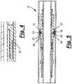
- FIG. 4 shows the setting arrangement of FIG. 3 , after shearing
- FIG. 5 shows the seal arrangement of FIG. 1 , in a fully set configuration
- FIG. 6 is a graph illustrating the relationship between the setting force applied to the sealing elements of the seal arrangement of FIG. 1 , and the degree of compression of the sealing elements;
- FIG. 7 is a sectional view of a seal arrangement in accordance with a second embodiment of the present invention, in an unset configuration
- FIG. 8 shows the seal arrangement of FIG. 7 , in a partially set configuration
- FIG. 9 is an enlarged sectional view of area 9 of FIG. 7 , showing a shearable setting arrangement
- FIG. 10 shows the setting arrangement of FIG. 9 , after shearing
- FIG. 11 shows the seal arrangement of FIG. 7 , in a fully set configuration
- FIG. 12 is a sectional view of a seal arrangement in accordance with a third embodiment of the present invention, in an unset configuration
- FIG. 13 shows the seal arrangement of FIG. 12 , in a set configuration
- FIG. 14 is a graph illustrating the relationship between the setting force applied to the sealing elements of the seal arrangement of FIG. 12 , and the degree of compression of the sealing elements;
- FIG. 15 is a sectional view of a seal arrangement in accordance with a fourth embodiment of the present invention, in an unset configuration
- FIG. 16 shows the seal arrangement of FIG. 15 , in a set configuration
- FIG. 17 is a graph illustrating the relationship between the setting force applied to the sealing elements of the seal arrangement of FIG. 15 , and the degree of compression of the sealing elements.
- FIG. 1 of the drawings is a sectional view of a seal arrangement 10 in accordance with a first embodiment of the present invention.
- the seal arrangement 10 is illustrated in an unset configuration.
- Embodiments of the present invention may be utilised in a range of environments and applications, however the embodiments described herein are primarily intended in use of downhole applications, and as such may be employed in the oil and gas exploration and extraction industry.
- the seal arrangement 10 is illustrated located within bore-lining tubing, which in this example is metal casing 12 .
- bore-lining tubing which in this example is metal casing 12 .
- the left-hand end of the Figure is representative of the upper or uphole end, while the right-hand end of the Figure is representative of the lower or downhole end.
- the sealing arrangement 10 will be provided in combination with an actuating arrangement, which would typically be located to the uphole end of the arrangement 10 .
- an actuating arrangement which would typically be located to the uphole end of the arrangement 10 .
- chain dotted lines 14 only the lower end of an actuating mechanism is indicated by chain dotted lines 14 .
- the seal arrangement 10 comprises a tubular body in the form of a mandrel 16 which may form part of a tubular string, or which may form part of a discrete tool or device.
- a tubular body in the form of a mandrel 16 which may form part of a tubular string, or which may form part of a discrete tool or device.
- Mounted on the mandrel 16 are first and second sealing elements 18 , 20 .
- the lower end of the first sealing element 18 is fixed to the mandrel 16
- other parts of the first sealing element 18 and the second sealing element 20 may be axially moveable relative to the mandrel 16 , and may be moved towards the lower end of the first sealing element 18 by the actuating arrangement 14 .
- Each sealing element, 18 , 20 includes an axially and circumferentially extending metal member 22 , 24 having a form selected such that the member 22 , 24 will deform or buckle on experiencing an axially compressive setting force.
- the member 22 of the first sealing element 18 has a lower end 26 coupled to a ring or mandrel 28 fixed to an inner sleeve 30 which is itself fixed and sealed to the outer surface of the mandrel 16 by set screws 32 and a chevron seal 34 .
- An upper end 36 of the member 22 is joined to a ring 38 which extends around the mandrel 16 and features an inwardly extending annular lip 40 and an outwardly extending annular rib 42 .
- the member 24 of the second sealing element 20 is essentially a mirror image of the member 22 , having a lower end 44 attached to the ring 38 and an upper end 45 attached to an end ring 46 which, unlike the end ring 28 , is axially moveable on the mandrel 16 , as will be described.
- the axially and circumferentially extending members 22 , 24 , the end rings 28 , 46 and the central ring 38 are formed from a single piece of metal.
- the end ring 46 is threaded and pinned to the lower end of a setting mandrel 48 , the upper end of which is threaded and pinned to the lower end of the actuating arrangement 14 .
- an axial support member in the form of a shear sleeve 50 extends between a shoulder 52 on the setting mandrel 48 and the upper face of the annular lip 40 .
- the inner surfaces of the members 22 , 24 and the respective end rings 28 , 38 , 46 in combination with the outer surface of the mandrel 16 define respective enclosed volumes 54 , 56 which are occupied by a non-compressible but compliant material such as polytetrafluoroethylene (PTFE), such as is sold under the Teflon trademark.
- PTFE polytetrafluoroethylene
- Each member 22 , 24 has a generally bulbous form and extends radially inwardly between the respective end rings 28 , 46 and the central ring 38 , creating a generally triangular-section volume between the outer surface of each member 22 , 24 and the rib 42 .
- Each volume is at least partially occupied by a generally triangular-section rubber ring 58 , 60 , such that each ring 58 , 60 has a generally cylindrical outer surface.
- the smaller section ends of each ring 58 , 60 engage respective circumferential lips 62 , 64 formed on the outer surface of the members 22 , 24 .
- the larger section ends of each ring 58 , 60 are shaped to engage and co-operate with the rib 42 as the seal arrangement 10 is set, as will be described.
- the surfaces of the rings 58 , 60 and the rib 42 are initially spaced apart, as the seal arrangement 10 is set the surfaces move together and into contact, and as such the rings 58 , 60 may include respective fluid release ports 66 , 68 to prevent fluid becoming trapped between the surfaces.
- O-rings 70 , 72 are located on the outer surface of the members 22 , 24 between the ends 36 , 44 and the base of the rib 42 .
- FIG. 2 of the drawings illustrates the seal arrangement 10 in a partially-set configuration.
- the setting mandrel 48 is urged downwardly relative to the mandrel 16 .
- This compressive force is transferred directly from the setting mandrel 48 to the central ring 38 via the shear sleeve 50 .
- the second sealing element 20 does not initially experience any compression.
- the first sealing element 18 is compressed and will deform as illustrated in FIG. 2 , that is the central ring 38 moving towards the lower end ring 28 , resulting in buckling of the member 22 , pushing the outer surface of the member 22 radially outwards into contact with the casing 12 .
- the member 22 is configured such that the annular lip 40 engages the casing 12 , the relatively small contact area provided by the lip 40 creating a high pressure zone which tends to deform the lip 40 preferentially against the casing wall, thus anchoring and sealing the member 22 to the casing 12 . It will also be noted that the thinner section end of the rubber ring 58 has been pushed outwardly into contact with the casing 12 , while the thicker section end of the ring 58 has been pushed into contact with and over the top of the rib 42 .
- FIGS. 3 and 4 of the drawings illustrating the configuration of the sleeve 50 before and after failure.
- the setting force applied by the setting mandrel 48 bears on the end ring 46 , compressing and extending the second sealing element 20 in a similar manner to the previously set first sealing element 18 .
- the fully-set sealing arrangement 10 is illustrated in FIG. 5 of the drawings.
- set sealing elements 18 , 20 are substantially symmetrical about a lateral plane and that the rubber rings 58 , 60 have been pressed together to form a generally V-section rubber seal element.
- the annular rib 42 controls and supports the rings 58 , 60 , and in turn the rings 58 , 60 support and control the deformation of the members 22 , 24 .
- FIG. 6 of the drawings is a graph illustrating the relationship between the setting force applied to the sealing elements 18 , 20 and the degree of compression of the sealing elements.
- the section of the graph between points A and B illustrates initial compression of the first sealing element 18 , comprising an initial degree of elastic deformation followed by plastic deformation until the outer surface of the member 22 contacts the casing at point B. This is followed by a further degree of compression, which effectively energises the element 18 .
- the shear sleeve 50 fails, resulting in initiation of the setting of the second sealing element 20 .
- the seal arrangement 10 may be retained in the set position by, for example, providing a ratchet arrangement on the actuating arrangement 14 . Subsequently the ratchet arrangement may be released, allowing the sealing elements 18 , 20 to be at least partially retracted, to permit retrieval of the seal arrangement 10 from the bore.
- first member lower end 26 and the second member upper end 45 are positioned towards the outer diameter of the respective end rings 28 , 46 .
- FIG. 7 through 11 of the drawings illustrate a sealing arrangement 110 in accordance with a second embodiment of the present invention.
- the seal arrangement 110 shares many features with the seal arrangement 10 described above, and in the interests of brevity those common features will not be described again in any detail.
- the axially and circumferentially extending members 122 , 124 have a slightly different form, in that the first member lower end 126 and the second member upper end 145 are positioned radially inwardly as compared to the corresponding ends 26 , 45 of the members 22 , 24 of the first embodiment.
- shear sleeve 150 of the second embodiment is formed of two separate sleeves 150 a, 150 b which are initially fixed together but may move axially relative to one another following shearing.
- FIGS. 12 and 13 of the drawings illustrate a sealing arrangement 210 in accordance with a third embodiment of the present invention.
- FIG. 12 presents the sealing arrangement 210 in an unset configuration
- FIG. 13 presents the sealing arrangement 210 in a set configuration.
- the seal arrangement 210 again shares many features with the seal arrangements 10 and 110 described above, and in the interests of brevity those common features will not be described again in any detail.
- the respective enclosed volumes 254 , 256 of the axially and circumferentially extending metal member 222 , 224 are now only partially filled with the non-compressible but compliant material e.g. polytetrafluoroethylene (PTFE), granules or nano-ceramics.
- the enclosed volumes 254 , 256 may also comprise a grease 274 , 276 .
- the presence of the grease 274 , 276 helps to prevent mechanical failure of the sealing elements 218 , 220 due to hydrostatic pressures experienced during the deployment of the seal arrangement 210 .
- the seal arrangement 210 is sealingly engaged with the mandrel at both outer extremities by mandrel seals 234 .
- This configuration presents a full annular piston to area to differential pressure from either direction, thus effectively: further axially compressing the sealing elements 218 , 220 into increased sealing engagement with the bore wall; presenting a collapsing pressure regime to the seal arrangement 210 which is fully supported in collapse due to the PTFE filled void, and removes a potential burst regime on the sealing elements 218 when exposed to an uphole differential pressure, as is present within the previously described seal arrangements 10 , 110 .
- a vent 280 provides a means a means of fluid communication to and from the enclosed volumes 254 , thus providing an exhaust for the grease 274 , 276 during compression of the respective sealing element 218 , 220 .
- Ejection of the grease 274 , 276 during the compression process has the advantage of providing a means for flushing away unwanted well fluids and or solid debris from the seal apparatus 210 . It may also act as a lubricant, thus enhancing the lifetime of the seal apparatus 210 .
- the outer surface of the rubber rings 258 , 260 also now comprise a non-uniform profile (e.g. a tapered or scalloped profile). Shaping of the outer surface of the rubber rings 258 , 260 in this manner is found to favourably bias the deformation of these components during setting of the respective sealing elements 218 , 220 .
- FIG. 14 of the drawings which is a graph illustrating the relationship between the setting force applied to the sealing elements 218 , 220 and the degree of compression of the sealing elements 218 , 220 .
- the section of the graph between points A and B illustrates initial plastic deformation of the first sealing element 218 while Section B to C corresponds to the radially outwards deformation of the axially and circumferentially extending metal member 222 .
- FIGS. 15 and 16 of the drawings illustrate a sealing arrangement 310 in accordance with a fourth embodiment of the present invention.
- FIG. 15 presents the sealing arrangement 310 in an unset configuration
- FIG. 16 presents the sealing arrangement 310 in a set configuration.
- the seal arrangement 310 again shares many features with the seal arrangements 10 , 110 , 210 described above, and in the interests of brevity those common features will not be described again in any detail.
- the sealing arrangement 310 comprises a travel limiter, in the form of a solid ring 390 located within the within the enclosed volume 354 .
- the solid ring 390 provides a means for preventing over extension of the axially and circumferentially extending member 322 during setting of the first sealing element 318 .
- the impact of the solid ring 390 can be seen within the corresponding graph of FIG. 17 which illustrates the relationship between the setting force applied to the sealing elements 318 , 320 and the degree of compression of the sealing elements 318 , 320 .
- the solid ring 390 results in the vertical section of the curve located between points C and D.
- the sealing arrangement comprises a body and first and second sealing elements mounted thereon.
- the sealing elements are each movable between a retracted configuration and an extended configuration and are configured to move from the retracted configuration to the extended configuration in response to an axial compression.
- the second sealing element is however maintained in its retracted configuration until the first sealing element has moved from its retracted configuration to its extended configuration.
- the sequential extension of the sealing elements can deform to assume the extended configuration under compression and the progression and the form of the deformation can be arranged to improve the quality of the seal achieved.
- An extended sealing element in engagement with the bore wall may also serve as an anchor or retainer and facilitate application of a compression force to an intermediate sealing element.
Landscapes
- Life Sciences & Earth Sciences (AREA)
- Engineering & Computer Science (AREA)
- Geology (AREA)
- Mining & Mineral Resources (AREA)
- Physics & Mathematics (AREA)
- Environmental & Geological Engineering (AREA)
- Fluid Mechanics (AREA)
- General Life Sciences & Earth Sciences (AREA)
- Geochemistry & Mineralogy (AREA)
- Gasket Seals (AREA)
- Sealing Devices (AREA)
Abstract
Description
Claims (30)
Applications Claiming Priority (4)
| Application Number | Priority Date | Filing Date | Title |
|---|---|---|---|
| GB1405009.0 | 2014-03-20 | ||
| GBGB1405009.0A GB201405009D0 (en) | 2014-03-20 | 2014-03-20 | Seal arrangement |
| GB1405009 | 2014-03-20 | ||
| PCT/GB2015/050845 WO2015140579A1 (en) | 2014-03-20 | 2015-03-20 | Seal arrangement |
Publications (2)
| Publication Number | Publication Date |
|---|---|
| US20170130552A1 US20170130552A1 (en) | 2017-05-11 |
| US11401774B2 true US11401774B2 (en) | 2022-08-02 |
Family
ID=50686610
Family Applications (1)
| Application Number | Title | Priority Date | Filing Date |
|---|---|---|---|
| US15/127,518 Active 2035-12-14 US11401774B2 (en) | 2014-03-20 | 2015-03-20 | Seal arrangement |
Country Status (6)
| Country | Link |
|---|---|
| US (1) | US11401774B2 (en) |
| EP (1) | EP3119982B1 (en) |
| AU (1) | AU2015233160B2 (en) |
| CA (1) | CA2943276C (en) |
| GB (2) | GB201405009D0 (en) |
| WO (1) | WO2015140579A1 (en) |
Families Citing this family (5)
| Publication number | Priority date | Publication date | Assignee | Title |
|---|---|---|---|---|
| US10655425B2 (en) * | 2015-07-01 | 2020-05-19 | Shell Oil Company | Method and system for sealing an annulur space around an expanded well tubular |
| GB201818114D0 (en) | 2018-11-06 | 2018-12-19 | Oil States Ind Uk Ltd | Apparatus and method relating to managed pressure drilling |
| EP3963167B1 (en) | 2019-05-03 | 2025-10-22 | Oil States Industries (UK) Limited | Apparatus and method relating to managed pressure drilling |
| US11578555B2 (en) * | 2019-08-01 | 2023-02-14 | Vertice Oil Tools Inc. | Methods and systems for a frac plug |
| US11072992B1 (en) * | 2020-04-14 | 2021-07-27 | Halliburton Energy Services, Inc. | Frac plug high expansion element retainer |
Citations (29)
| Publication number | Priority date | Publication date | Assignee | Title |
|---|---|---|---|---|
| US4765404A (en) | 1987-04-13 | 1988-08-23 | Drilex Systems, Inc. | Whipstock packer assembly |
| US4791992A (en) * | 1987-08-18 | 1988-12-20 | Dresser Industries, Inc. | Hydraulically operated and released isolation packer |
| US5467822A (en) * | 1991-08-31 | 1995-11-21 | Zwart; Klaas J. | Pack-off tool |
| US20030079887A1 (en) * | 2001-10-30 | 2003-05-01 | Smith International, Inc. | High pressure sealing apparatus and method |
| US20050161232A1 (en) * | 2004-01-27 | 2005-07-28 | Schlumberger Technology Corporation | Annular Barrier Tool |
| US7322416B2 (en) * | 2004-05-03 | 2008-01-29 | Halliburton Energy Services, Inc. | Methods of servicing a well bore using self-activating downhole tool |
| US20080053652A1 (en) | 2006-08-29 | 2008-03-06 | Pierre-Yves Corre | Drillstring packer assembly |
| US20080061510A1 (en) | 2006-09-11 | 2008-03-13 | Schlumberger Technology Corporation | Forming a metal-to-metal seal in a well |
| US20090058017A1 (en) * | 2007-09-05 | 2009-03-05 | Baker Hughes Incorporated | Downhole tubular seal system and method |
| US20090205843A1 (en) | 2008-02-19 | 2009-08-20 | Varadaraju Gandikota | Expandable packer |
| US20090255692A1 (en) * | 2008-04-14 | 2009-10-15 | Baker Hughes Incorporated | Zero-Relaxation Packer Setting Lock System |
| US20110062670A1 (en) | 2009-09-14 | 2011-03-17 | Baker Hughes Incorporated | Load delayed seal element, system, and method |
| US20110186308A1 (en) * | 2010-01-29 | 2011-08-04 | Baker Hughes Incorporated | Asymmetric seal and method |
| US20120006530A1 (en) * | 2010-07-06 | 2012-01-12 | Halliburton Energy Services, Inc. | Packing element system with profiled surface |
| US20120273236A1 (en) * | 2011-04-27 | 2012-11-01 | Varadaraju Gandikota | Expandable open-hole anchor |
| US20130112398A1 (en) * | 2009-09-14 | 2013-05-09 | Max White | Modified packer with non-extrusion ring |
| GB2497124A (en) * | 2011-12-01 | 2013-06-05 | Xtreme Innovations Ltd | Multiple extendable seals or anchors |
| US20130140041A1 (en) * | 2011-12-01 | 2013-06-06 | Baker Hughes Incorporated | Selectively disengagable sealing system |
| US20130147121A1 (en) * | 2011-12-13 | 2013-06-13 | Baker Hughes Incorporated | Backup System for Packer Sealing Element |
| US20130180732A1 (en) * | 2012-01-13 | 2013-07-18 | Frank V. Acosta | Multiple Ramp Compression Packer |
| US20130192853A1 (en) * | 2010-10-06 | 2013-08-01 | Packers Plus Energy Services Inc. | Wellbore packer back-up ring assembly, packer and method |
| US8561709B2 (en) * | 2007-04-12 | 2013-10-22 | Baker Hughes Incorporated | Liner top packer seal assembly and method |
| US20130299199A1 (en) * | 2012-05-09 | 2013-11-14 | Utex Industries, Inc. | Seat assembly with counter for isolating fracture zones in a well |
| WO2014006392A2 (en) | 2012-07-04 | 2014-01-09 | Xtreme Innovations Limited | Downhole tool |
| US8727027B2 (en) * | 2008-02-07 | 2014-05-20 | Swellfix B.V. | Downhole seal |
| US8887818B1 (en) * | 2011-11-02 | 2014-11-18 | Diamondback Industries, Inc. | Composite frac plug |
| US20150252647A1 (en) * | 2014-03-10 | 2015-09-10 | Shuhao Liu | Stress-buffer release lever and downhole plugging apparatus |
| US9145755B2 (en) * | 2013-05-02 | 2015-09-29 | Halliburton Energy Services, Inc. | Sealing annular gaps in a well |
| US9376884B2 (en) * | 2007-12-11 | 2016-06-28 | Rubberatkins Limited | Packing element |
Family Cites Families (1)
| Publication number | Priority date | Publication date | Assignee | Title |
|---|---|---|---|---|
| CA1215320A (en) * | 1984-12-19 | 1986-12-16 | Mike A. Luke | Downhole steam packer |
-
2014
- 2014-03-20 GB GBGB1405009.0A patent/GB201405009D0/en not_active Ceased
-
2015
- 2015-03-20 GB GB1504798.8A patent/GB2524404B/en active Active
- 2015-03-20 WO PCT/GB2015/050845 patent/WO2015140579A1/en not_active Ceased
- 2015-03-20 AU AU2015233160A patent/AU2015233160B2/en active Active
- 2015-03-20 US US15/127,518 patent/US11401774B2/en active Active
- 2015-03-20 EP EP15718075.3A patent/EP3119982B1/en active Active
- 2015-03-20 CA CA2943276A patent/CA2943276C/en active Active
Patent Citations (30)
| Publication number | Priority date | Publication date | Assignee | Title |
|---|---|---|---|---|
| US4765404A (en) | 1987-04-13 | 1988-08-23 | Drilex Systems, Inc. | Whipstock packer assembly |
| US4791992A (en) * | 1987-08-18 | 1988-12-20 | Dresser Industries, Inc. | Hydraulically operated and released isolation packer |
| US5467822A (en) * | 1991-08-31 | 1995-11-21 | Zwart; Klaas J. | Pack-off tool |
| US20030079887A1 (en) * | 2001-10-30 | 2003-05-01 | Smith International, Inc. | High pressure sealing apparatus and method |
| US20050161232A1 (en) * | 2004-01-27 | 2005-07-28 | Schlumberger Technology Corporation | Annular Barrier Tool |
| US7322416B2 (en) * | 2004-05-03 | 2008-01-29 | Halliburton Energy Services, Inc. | Methods of servicing a well bore using self-activating downhole tool |
| US20080053652A1 (en) | 2006-08-29 | 2008-03-06 | Pierre-Yves Corre | Drillstring packer assembly |
| US20080061510A1 (en) | 2006-09-11 | 2008-03-13 | Schlumberger Technology Corporation | Forming a metal-to-metal seal in a well |
| US8561709B2 (en) * | 2007-04-12 | 2013-10-22 | Baker Hughes Incorporated | Liner top packer seal assembly and method |
| US20090058017A1 (en) * | 2007-09-05 | 2009-03-05 | Baker Hughes Incorporated | Downhole tubular seal system and method |
| US9376884B2 (en) * | 2007-12-11 | 2016-06-28 | Rubberatkins Limited | Packing element |
| US8727027B2 (en) * | 2008-02-07 | 2014-05-20 | Swellfix B.V. | Downhole seal |
| US20090205843A1 (en) | 2008-02-19 | 2009-08-20 | Varadaraju Gandikota | Expandable packer |
| US20090255692A1 (en) * | 2008-04-14 | 2009-10-15 | Baker Hughes Incorporated | Zero-Relaxation Packer Setting Lock System |
| US20110062670A1 (en) | 2009-09-14 | 2011-03-17 | Baker Hughes Incorporated | Load delayed seal element, system, and method |
| US20130112398A1 (en) * | 2009-09-14 | 2013-05-09 | Max White | Modified packer with non-extrusion ring |
| US20110186308A1 (en) * | 2010-01-29 | 2011-08-04 | Baker Hughes Incorporated | Asymmetric seal and method |
| US20120006530A1 (en) * | 2010-07-06 | 2012-01-12 | Halliburton Energy Services, Inc. | Packing element system with profiled surface |
| US20130192853A1 (en) * | 2010-10-06 | 2013-08-01 | Packers Plus Energy Services Inc. | Wellbore packer back-up ring assembly, packer and method |
| US20120273236A1 (en) * | 2011-04-27 | 2012-11-01 | Varadaraju Gandikota | Expandable open-hole anchor |
| US8887818B1 (en) * | 2011-11-02 | 2014-11-18 | Diamondback Industries, Inc. | Composite frac plug |
| US20130140041A1 (en) * | 2011-12-01 | 2013-06-06 | Baker Hughes Incorporated | Selectively disengagable sealing system |
| WO2013079965A2 (en) | 2011-12-01 | 2013-06-06 | Xtreme Innovations Limited | Apparatus for use in a fluid conduit |
| GB2497124A (en) * | 2011-12-01 | 2013-06-05 | Xtreme Innovations Ltd | Multiple extendable seals or anchors |
| US20130147121A1 (en) * | 2011-12-13 | 2013-06-13 | Baker Hughes Incorporated | Backup System for Packer Sealing Element |
| US20130180732A1 (en) * | 2012-01-13 | 2013-07-18 | Frank V. Acosta | Multiple Ramp Compression Packer |
| US20130299199A1 (en) * | 2012-05-09 | 2013-11-14 | Utex Industries, Inc. | Seat assembly with counter for isolating fracture zones in a well |
| WO2014006392A2 (en) | 2012-07-04 | 2014-01-09 | Xtreme Innovations Limited | Downhole tool |
| US9145755B2 (en) * | 2013-05-02 | 2015-09-29 | Halliburton Energy Services, Inc. | Sealing annular gaps in a well |
| US20150252647A1 (en) * | 2014-03-10 | 2015-09-10 | Shuhao Liu | Stress-buffer release lever and downhole plugging apparatus |
Non-Patent Citations (11)
| Title |
|---|
| Combined Search and Examination Report issued in the related GB Application 1504798.8, dated Jul. 1, 2015 (8 pages). |
| Communication pursuant to Article 94(3) EPC, issued in the related EP Application 15718075.3, dated Nov. 8, 2017 (3 pages). |
| Exam Report issued in Canadian Patent Application No. 2943276 dated Apr. 13, 2021, 4 pages. |
| Exam Report issued in Canadian Patent Application No. 2943276 dated Jan. 6, 2022, 7 pages. |
| Examination report issued in the related AU Application 2015233160, dated Aug. 30, 2018 (4 pages). |
| Examination Report issued in the related GB Application 1504798.8, dated Jan. 19, 2017 (4 pages). |
| Examination Report issued in the related GB Application 1504798.8, dated Jul. 7, 2017 (4 pages). |
| International Preliminary Report on Patentability issued in related PCT/GB2015/050845, dated Sep. 20, 2016 (7 pages). |
| International Search Report and Written Opinion issued in related PCT/GB2015/050845, dated Jul. 2, 2015 (10 pages). |
| Metaplex seal, published on Oct. 17, 2013, available from: https://www.youtube.com/watch?v=6dNS2JdvZBQ, Accessed on Jun. 23, 2015, (Xtreme Well Technology), Whole Video—(details of the videos are as provided in the GB combined search and examination report dated Jul. 1, 2015 listed in this IDS, line 3 under NPL). |
| Metaplex seal, published on Oct. 17, 2013, available from: https://www.youtube.com/watch?v=XZUt-Lrafc0, Accessed on Jun. 23, 2015, (Xtreme Well Technology), 16-31 Seconds—(details of the videos are as provided in the GB combined search and examination report dated Jul. 1, 2015 listed in this IDS, line 3 under NPL). |
Also Published As
| Publication number | Publication date |
|---|---|
| GB201405009D0 (en) | 2014-05-07 |
| EP3119982B1 (en) | 2018-12-12 |
| GB2524404B (en) | 2018-08-29 |
| AU2015233160A1 (en) | 2016-10-13 |
| GB2524404A (en) | 2015-09-23 |
| US20170130552A1 (en) | 2017-05-11 |
| CA2943276C (en) | 2023-09-26 |
| EP3119982A1 (en) | 2017-01-25 |
| CA2943276A1 (en) | 2015-09-24 |
| GB201504798D0 (en) | 2015-05-06 |
| WO2015140579A1 (en) | 2015-09-24 |
| AU2015233160B2 (en) | 2019-09-12 |
Similar Documents
| Publication | Publication Date | Title |
|---|---|---|
| US8109340B2 (en) | High-pressure/high temperature packer seal | |
| NL1041829B1 (en) | Packing element back-up system incorporating iris mechanism | |
| US10174579B2 (en) | Extrusion-resistant seals for expandable tubular assembly | |
| US6666276B1 (en) | Downhole radial set packer element | |
| US10570693B2 (en) | Apparatus for use in a fluid conduit | |
| US8714273B2 (en) | High expansion metal seal system | |
| US11401774B2 (en) | Seal arrangement | |
| US9752419B2 (en) | Morphing tubulars | |
| US8973667B2 (en) | Packing element with full mechanical circumferential support | |
| AU2016424204B2 (en) | High expansion metal back-up ring for packers and bridge plugs | |
| US10174581B2 (en) | Method and apparatus to utilize a deformable filler ring | |
| CA2713684C (en) | High pressure/high temperature packer seal | |
| NO20101178A1 (en) | High pressure / high temperature gasket seal |
Legal Events
| Date | Code | Title | Description |
|---|---|---|---|
| AS | Assignment |
Owner name: XTREME WELL TECHNOLOGY LIMITED, UNITED KINGDOM Free format text: ASSIGNMENT OF ASSIGNORS INTEREST;ASSIGNOR:MOYES, PETER;REEL/FRAME:040222/0557 Effective date: 20161031 |
|
| STPP | Information on status: patent application and granting procedure in general |
Free format text: NON FINAL ACTION MAILED |
|
| STPP | Information on status: patent application and granting procedure in general |
Free format text: RESPONSE TO NON-FINAL OFFICE ACTION ENTERED AND FORWARDED TO EXAMINER |
|
| FEPP | Fee payment procedure |
Free format text: ENTITY STATUS SET TO UNDISCOUNTED (ORIGINAL EVENT CODE: BIG.); ENTITY STATUS OF PATENT OWNER: LARGE ENTITY |
|
| STPP | Information on status: patent application and granting procedure in general |
Free format text: FINAL REJECTION MAILED |
|
| STPP | Information on status: patent application and granting procedure in general |
Free format text: DOCKETED NEW CASE - READY FOR EXAMINATION |
|
| STPP | Information on status: patent application and granting procedure in general |
Free format text: NON FINAL ACTION MAILED |
|
| STPP | Information on status: patent application and granting procedure in general |
Free format text: RESPONSE TO NON-FINAL OFFICE ACTION ENTERED AND FORWARDED TO EXAMINER |
|
| STPP | Information on status: patent application and granting procedure in general |
Free format text: FINAL REJECTION MAILED |
|
| STPP | Information on status: patent application and granting procedure in general |
Free format text: RESPONSE AFTER FINAL ACTION FORWARDED TO EXAMINER |
|
| AS | Assignment |
Owner name: SCHLUMBERGER TECHNOLOGY CORPORATION, TEXAS Free format text: ASSIGNMENT OF ASSIGNORS INTEREST;ASSIGNOR:XTREME WELL TECHNOLOGY LIMITED;REEL/FRAME:053614/0729 Effective date: 20200810 |
|
| STPP | Information on status: patent application and granting procedure in general |
Free format text: DOCKETED NEW CASE - READY FOR EXAMINATION |
|
| STPP | Information on status: patent application and granting procedure in general |
Free format text: RESPONSE TO NON-FINAL OFFICE ACTION ENTERED AND FORWARDED TO EXAMINER |
|
| STPP | Information on status: patent application and granting procedure in general |
Free format text: FINAL REJECTION MAILED |
|
| STPP | Information on status: patent application and granting procedure in general |
Free format text: RESPONSE AFTER FINAL ACTION FORWARDED TO EXAMINER |
|
| STPP | Information on status: patent application and granting procedure in general |
Free format text: ADVISORY ACTION MAILED |
|
| STPP | Information on status: patent application and granting procedure in general |
Free format text: DOCKETED NEW CASE - READY FOR EXAMINATION |
|
| STPP | Information on status: patent application and granting procedure in general |
Free format text: NON FINAL ACTION MAILED |
|
| STPP | Information on status: patent application and granting procedure in general |
Free format text: RESPONSE TO NON-FINAL OFFICE ACTION ENTERED AND FORWARDED TO EXAMINER |
|
| STPP | Information on status: patent application and granting procedure in general |
Free format text: NOTICE OF ALLOWANCE MAILED -- APPLICATION RECEIVED IN OFFICE OF PUBLICATIONS |
|
| STCF | Information on status: patent grant |
Free format text: PATENTED CASE |
|
| MAFP | Maintenance fee payment |
Free format text: PAYMENT OF MAINTENANCE FEE, 4TH YEAR, LARGE ENTITY (ORIGINAL EVENT CODE: M1551); ENTITY STATUS OF PATENT OWNER: LARGE ENTITY Year of fee payment: 4 |