US11399618B2 - Methods and applicators for applying skin-tightening film products - Google Patents
Methods and applicators for applying skin-tightening film products Download PDFInfo
- Publication number
- US11399618B2 US11399618B2 US15/965,647 US201815965647A US11399618B2 US 11399618 B2 US11399618 B2 US 11399618B2 US 201815965647 A US201815965647 A US 201815965647A US 11399618 B2 US11399618 B2 US 11399618B2
- Authority
- US
- United States
- Prior art keywords
- skin
- stencil
- tightening
- open spaces
- stamp
- Prior art date
- Legal status (The legal status is an assumption and is not a legal conclusion. Google has not performed a legal analysis and makes no representation as to the accuracy of the status listed.)
- Active, expires
Links
Images


Classifications
-
- A—HUMAN NECESSITIES
- A45—HAND OR TRAVELLING ARTICLES
- A45D—HAIRDRESSING OR SHAVING EQUIPMENT; EQUIPMENT FOR COSMETICS OR COSMETIC TREATMENTS, e.g. FOR MANICURING OR PEDICURING
- A45D40/00—Casings or accessories specially adapted for storing or handling solid or pasty toiletry or cosmetic substances, e.g. shaving soaps or lipsticks
- A45D40/26—Appliances specially adapted for applying pasty paint, e.g. using roller, using a ball
- A45D40/261—Appliances specially adapted for applying pasty paint, e.g. using roller, using a ball using a ball, a roller or the like
-
- A—HUMAN NECESSITIES
- A45—HAND OR TRAVELLING ARTICLES
- A45D—HAIRDRESSING OR SHAVING EQUIPMENT; EQUIPMENT FOR COSMETICS OR COSMETIC TREATMENTS, e.g. FOR MANICURING OR PEDICURING
- A45D34/00—Containers or accessories specially adapted for handling liquid toiletry or cosmetic substances, e.g. perfumes
- A45D34/04—Appliances specially adapted for applying liquid, e.g. using roller or ball
- A45D34/041—Appliances specially adapted for applying liquid, e.g. using roller or ball using a roller, a disc or a ball
-
- A—HUMAN NECESSITIES
- A45—HAND OR TRAVELLING ARTICLES
- A45D—HAIRDRESSING OR SHAVING EQUIPMENT; EQUIPMENT FOR COSMETICS OR COSMETIC TREATMENTS, e.g. FOR MANICURING OR PEDICURING
- A45D34/00—Containers or accessories specially adapted for handling liquid toiletry or cosmetic substances, e.g. perfumes
- A45D34/04—Appliances specially adapted for applying liquid, e.g. using roller or ball
-
- A—HUMAN NECESSITIES
- A61—MEDICAL OR VETERINARY SCIENCE; HYGIENE
- A61K—PREPARATIONS FOR MEDICAL, DENTAL OR TOILETRY PURPOSES
- A61K8/00—Cosmetics or similar toiletry preparations
- A61K8/02—Cosmetics or similar toiletry preparations characterised by special physical form
- A61K8/0204—Specific forms not provided for by any of groups A61K8/0208 - A61K8/14
-
- A—HUMAN NECESSITIES
- A61—MEDICAL OR VETERINARY SCIENCE; HYGIENE
- A61K—PREPARATIONS FOR MEDICAL, DENTAL OR TOILETRY PURPOSES
- A61K8/00—Cosmetics or similar toiletry preparations
- A61K8/02—Cosmetics or similar toiletry preparations characterised by special physical form
- A61K8/0241—Containing particulates characterized by their shape and/or structure
-
- A—HUMAN NECESSITIES
- A61—MEDICAL OR VETERINARY SCIENCE; HYGIENE
- A61K—PREPARATIONS FOR MEDICAL, DENTAL OR TOILETRY PURPOSES
- A61K8/00—Cosmetics or similar toiletry preparations
- A61K8/18—Cosmetics or similar toiletry preparations characterised by the composition
- A61K8/72—Cosmetics or similar toiletry preparations characterised by the composition containing organic macromolecular compounds
- A61K8/81—Cosmetics or similar toiletry preparations characterised by the composition containing organic macromolecular compounds obtained by reactions involving only carbon-to-carbon unsaturated bonds
- A61K8/8141—Compositions of homopolymers or copolymers of compounds having one or more unsaturated aliphatic radicals, each having only one carbon-to-carbon double bond, and at least one being terminated by only one carboxyl radical, or of salts, anhydrides, esters, amides, imides or nitriles thereof; Compositions of derivatives of such polymers
- A61K8/8147—Homopolymers or copolymers of acids; Metal or ammonium salts thereof, e.g. crotonic acid, (meth)acrylic acid; Compositions of derivatives of such polymers
-
- A—HUMAN NECESSITIES
- A61—MEDICAL OR VETERINARY SCIENCE; HYGIENE
- A61K—PREPARATIONS FOR MEDICAL, DENTAL OR TOILETRY PURPOSES
- A61K8/00—Cosmetics or similar toiletry preparations
- A61K8/18—Cosmetics or similar toiletry preparations characterised by the composition
- A61K8/72—Cosmetics or similar toiletry preparations characterised by the composition containing organic macromolecular compounds
- A61K8/81—Cosmetics or similar toiletry preparations characterised by the composition containing organic macromolecular compounds obtained by reactions involving only carbon-to-carbon unsaturated bonds
- A61K8/8141—Compositions of homopolymers or copolymers of compounds having one or more unsaturated aliphatic radicals, each having only one carbon-to-carbon double bond, and at least one being terminated by only one carboxyl radical, or of salts, anhydrides, esters, amides, imides or nitriles thereof; Compositions of derivatives of such polymers
- A61K8/8152—Homopolymers or copolymers of esters, e.g. (meth)acrylic acid esters; Compositions of derivatives of such polymers
-
- A—HUMAN NECESSITIES
- A61—MEDICAL OR VETERINARY SCIENCE; HYGIENE
- A61K—PREPARATIONS FOR MEDICAL, DENTAL OR TOILETRY PURPOSES
- A61K8/00—Cosmetics or similar toiletry preparations
- A61K8/18—Cosmetics or similar toiletry preparations characterised by the composition
- A61K8/72—Cosmetics or similar toiletry preparations characterised by the composition containing organic macromolecular compounds
- A61K8/84—Cosmetics or similar toiletry preparations characterised by the composition containing organic macromolecular compounds obtained by reactions otherwise than those involving only carbon-carbon unsaturated bonds
- A61K8/87—Polyurethanes
-
- A—HUMAN NECESSITIES
- A61—MEDICAL OR VETERINARY SCIENCE; HYGIENE
- A61K—PREPARATIONS FOR MEDICAL, DENTAL OR TOILETRY PURPOSES
- A61K8/00—Cosmetics or similar toiletry preparations
- A61K8/18—Cosmetics or similar toiletry preparations characterised by the composition
- A61K8/72—Cosmetics or similar toiletry preparations characterised by the composition containing organic macromolecular compounds
- A61K8/84—Cosmetics or similar toiletry preparations characterised by the composition containing organic macromolecular compounds obtained by reactions otherwise than those involving only carbon-carbon unsaturated bonds
- A61K8/89—Polysiloxanes
- A61K8/896—Polysiloxanes containing atoms other than silicon, carbon, oxygen and hydrogen, e.g. dimethicone copolyol phosphate
- A61K8/898—Polysiloxanes containing atoms other than silicon, carbon, oxygen and hydrogen, e.g. dimethicone copolyol phosphate containing nitrogen, e.g. amodimethicone, trimethyl silyl amodimethicone or dimethicone propyl PG-betaine
-
- A—HUMAN NECESSITIES
- A61—MEDICAL OR VETERINARY SCIENCE; HYGIENE
- A61K—PREPARATIONS FOR MEDICAL, DENTAL OR TOILETRY PURPOSES
- A61K8/00—Cosmetics or similar toiletry preparations
- A61K8/18—Cosmetics or similar toiletry preparations characterised by the composition
- A61K8/92—Oils, fats or waxes; Derivatives thereof, e.g. hydrogenation products thereof
- A61K8/922—Oils, fats or waxes; Derivatives thereof, e.g. hydrogenation products thereof of vegetable origin
-
- A—HUMAN NECESSITIES
- A61—MEDICAL OR VETERINARY SCIENCE; HYGIENE
- A61Q—SPECIFIC USE OF COSMETICS OR SIMILAR TOILETRY PREPARATIONS
- A61Q19/00—Preparations for care of the skin
-
- A—HUMAN NECESSITIES
- A45—HAND OR TRAVELLING ARTICLES
- A45D—HAIRDRESSING OR SHAVING EQUIPMENT; EQUIPMENT FOR COSMETICS OR COSMETIC TREATMENTS, e.g. FOR MANICURING OR PEDICURING
- A45D2200/00—Details not otherwise provided for in A45D
- A45D2200/10—Details of applicators
-
- A—HUMAN NECESSITIES
- A45—HAND OR TRAVELLING ARTICLES
- A45D—HAIRDRESSING OR SHAVING EQUIPMENT; EQUIPMENT FOR COSMETICS OR COSMETIC TREATMENTS, e.g. FOR MANICURING OR PEDICURING
- A45D2200/00—Details not otherwise provided for in A45D
- A45D2200/10—Details of applicators
- A45D2200/1009—Applicators comprising a pad, tissue, sponge, or the like
- A45D2200/1018—Applicators comprising a pad, tissue, sponge, or the like comprising a pad, i.e. a cushion-like mass of soft material, with or without gripping means
-
- A—HUMAN NECESSITIES
- A45—HAND OR TRAVELLING ARTICLES
- A45D—HAIRDRESSING OR SHAVING EQUIPMENT; EQUIPMENT FOR COSMETICS OR COSMETIC TREATMENTS, e.g. FOR MANICURING OR PEDICURING
- A45D2200/00—Details not otherwise provided for in A45D
- A45D2200/15—Temperature
- A45D2200/155—Heating or cooling means, i.e. for storing or applying cosmetic products at a predetermined temperature
-
- A—HUMAN NECESSITIES
- A45—HAND OR TRAVELLING ARTICLES
- A45D—HAIRDRESSING OR SHAVING EQUIPMENT; EQUIPMENT FOR COSMETICS OR COSMETIC TREATMENTS, e.g. FOR MANICURING OR PEDICURING
- A45D2200/00—Details not otherwise provided for in A45D
- A45D2200/25—Kits
-
- A—HUMAN NECESSITIES
- A61—MEDICAL OR VETERINARY SCIENCE; HYGIENE
- A61K—PREPARATIONS FOR MEDICAL, DENTAL OR TOILETRY PURPOSES
- A61K2800/00—Properties of cosmetic compositions or active ingredients thereof or formulation aids used therein and process related aspects
- A61K2800/40—Chemical, physico-chemical or functional or structural properties of particular ingredients
- A61K2800/41—Particular ingredients further characterized by their size
- A61K2800/412—Microsized, i.e. having sizes between 0.1 and 100 microns
-
- A—HUMAN NECESSITIES
- A61—MEDICAL OR VETERINARY SCIENCE; HYGIENE
- A61K—PREPARATIONS FOR MEDICAL, DENTAL OR TOILETRY PURPOSES
- A61K2800/00—Properties of cosmetic compositions or active ingredients thereof or formulation aids used therein and process related aspects
- A61K2800/40—Chemical, physico-chemical or functional or structural properties of particular ingredients
- A61K2800/60—Particulates further characterized by their structure or composition
- A61K2800/65—Characterized by the composition of the particulate/core
- A61K2800/652—The particulate/core comprising organic material
-
- A—HUMAN NECESSITIES
- A61—MEDICAL OR VETERINARY SCIENCE; HYGIENE
- A61K—PREPARATIONS FOR MEDICAL, DENTAL OR TOILETRY PURPOSES
- A61K2800/00—Properties of cosmetic compositions or active ingredients thereof or formulation aids used therein and process related aspects
- A61K2800/80—Process related aspects concerning the preparation of the cosmetic composition or the storage or application thereof
- A61K2800/87—Application Devices; Containers; Packaging
Definitions
- a combination comprises a skin-tightening composition and an applicator configured to apply the skin-tightening composition in a discontinuous manner, wherein the applicator comprises an application surface having a plurality of first discontinuous subsurfaces separated by a continuous second subsurface, where the plurality of discontinuous subsurfaces are arranged in a repeating pattern; and a skin-tightening composition.
- the first subsurfaces are open spaces and the second subsurface forms ribs or strips between the open spaces.
- the open spaces have a non-isometric shape in the length and width dimensions.
- the open spaces have diamond, square, rectangular, or any other polygon shape in the length and width dimension.
- the open spaces have more than one shape.
- the open spaces have more than one size.
- the skin-tightening composition is provided in a container, and the applicator and skin-tightening composition are provided as a unit.
- the skin-tightening composition is selected from the group consisting of: anionic copolymers based on methacrylic acid and methyl methacrylate in a random, block, or alternating configuration, organopolysiloxanes, silicone-urethane copolymers, ethylenically unsaturated polycarbosiloxanes, silicone-urethane copolymers and an elastomer, an elastomer, an adhesive polymer, and a filler, and wax microparticles
- the combination comprises a stencil including a material having a first and second major surface forming opposite sides of the material, wherein the first and second surfaces are separated by a thickness of the material with open spaces in the material that traverse the material from the first major surface to the second major surface, wherein a majority of the open spaces have a similar shape to create a repeating pattern of open spaces along a length dimension and a width dimension of the material, and wherein the maximum average size of an open space in either a length dimension or width dimension is from 20 microns to 150 microns.
- the stencil is a sheet or a mesh of filaments.
- the stencil has an adhesive on one of the first or second major surfaces.
- the stencil has a backing sheet to which the stencil is adhered.
- the first subsurfaces are protrusions and the second subsurface forms grooves in between the first subsurfaces.
- outward facing surfaces of the distal ends of the protrusions have a non-isometric shape in the length and width dimensions.
- outward facing surfaces of the distal ends of the protrusions have a diamond, square, rectangular, or any other polygon shape in the length and width dimension.
- outward facing surfaces of the distal ends of the protrusions include more than one shape of outward facing surface.
- outward facing surfaces of the distal ends of the protrusions include more than one size of outward facing surfaces.
- outward facing surfaces of the distal ends of the protrusions lie along a planar surface.
- outward facing surfaces of the distal ends of the protrusions lie on a roller.
- outward facing surfaces of the distal ends of the protrusions collectively lie on a convex surface.
- outward facing surfaces of the distal ends of the protrusions lie on a convex surface curving upwards from a center in all dimensions.
- outward facing surfaces of the distal ends of the protrusions are flat.
- the combination comprises a stamp having protrusions extending from at least one surface, wherein outward facing surfaces of the protrusions collectively form a surface for stamping, a majority of the outward facing surfaces of the distal ends of the protrusions have a similar shape to create a repeating pattern along a length dimension and a width dimension, and wherein the maximum average size of the outward facing surface area of the distal ends of the protrusions in either a length dimension or width dimension is from 20 microns to 150 microns.
- a method of applying a skin-tightening composition comprises placing a stencil on a skin area, wherein the stencil includes a material having a first and second major surface forming opposite sides of the material, wherein the first and second surfaces are separated by a thickness of the material with open spaces in the material that traverse the material from the first major surface to the second major surface, wherein a majority of the open spaces have a similar shape to create a repeating pattern of open spaces along a length dimension and a width dimension of the material, and wherein the maximum average size of an open space in either a length dimension or width dimension is from 20 microns to 150 microns; applying a skin-tightening composition to the stencil while on the skin area; and removing the stencil from the skin area that leaves a patterned skin-tightening composition on the skin area.
- a method of applying a skin-tightening composition comprises providing a stamp having protrusions extending from at least one surface, wherein outward facing surfaces of the protrusions collectively form a surface for stamping, a majority of the outward facing surfaces of the distal ends of the protrusions have a similar shape to create a repeating pattern along a length dimension and a width dimension, and wherein the maximum average size of the outward facing surface area of the distal ends of the protrusions in either a length dimension or width dimension is from 20 microns to 150 microns; applying a skin-tightening composition at least on the outward facing surfaces of the protrusions and bringing the skin-tightening composition on the stamp in contact with a skin area; and withdrawing the stamp and leaving a patterned skin-tightening composition on the skin area.
- FIG. 1A is a diagrammatical illustration of a stencil applicator and a step of a method according to an embodiment
- FIG. 1B is a diagrammatical illustration of a stencil applicator and a step of a method according to an embodiment
- FIG. 1C is a diagrammatical illustration of a discontinuous film and a step of a method according to an embodiment
- FIG. 2A is a diagrammatical illustration of a stamp applicator and a step of a method according to an embodiment
- FIG. 2B is a diagrammatical illustration of a stamp applicator and a step of a method according to an embodiment
- FIG. 2C is a diagrammatical illustration of a stamp applicator and a step of a method according to an embodiment
- FIG. 2D is a diagrammatical illustration of a stamp applicator and a step of a method according to an embodiment
- FIG. 2E is a diagrammatical illustration of a discontinuous film and a step of a method according to an embodiment
- FIG. 2F is a diagrammatical illustration of a discontinuous film and a step of a method according to an embodiment
- FIG. 3A is a diagrammatical illustration of a discontinuous film
- FIG. 3B is a diagrammatical illustration of a discontinuous film
- FIG. 3C is a diagrammatical illustration of a discontinuous film
- FIG. 3D is a diagrammatical illustration of a discontinuous film
- FIG. 4 is a diagrammatical illustration of a stamp
- FIG. 5 is a diagrammatical illustration of a stencil
- FIG. 6 is a diagrammatical illustration of a stencil
- FIG. 7 is a diagrammatical illustration of a rolling stamp applicator
- FIG. 8 is a diagrammatical illustration of a cross section of the rolling stamp applicator of FIG. 7 ;
- FIG. 9 is a diagrammatical illustration of a rolling stamp applicator
- FIG. 10 is a diagrammatical illustration of a cross section of a rolling stamp applicator
- FIG. 11 is a diagrammatical illustration of a cross section of the rolling stamp applicator of FIG. 7 ;
- FIG. 12 is a diagrammatical illustration of a combination of a skin-tightening composition in a container and a stamp provided as a kit or unit;
- FIG. 13 is a diagrammatical illustration of a combination of a skin-tightening composition in a container and a stencil provided as a kit or unit.
- Skin-tightening polymeric film forming products are very effective at reducing the appearance of wrinkles and bags on the face and also on reducing sagging skin generally. However, some products can cause discomfort on the face and produce an unnatural look upon facial movement. Accordingly, this disclosure relates to applicators and methods for applying skin-tightening products that give more flexibility for the skin to move.
- Embodiments include a method and an applicator to apply skin-tightening film products on, for example, the face by generating a discontinuous film on the skin to provide more comfort and a more natural look of facial movement while retaining a good skin-tightening effect.
- Embodiments of applicators include a stamp or a stencil designed respectively with a continuous pattern such as a grid, or a discontinuous pattern with a non-isotropic shapes such as a diamond with which the skin-tightening film composition is applied on the skin.
- the composition is deposited on a patterned stamp.
- the composition is transferred onto the skin following the stamp pattern by pressing the stamp on the skin.
- a patterned stencil is applied onto the skin.
- the composition is then applied over the patterned stencil like in screen printing techniques. Then, the stencil is removed, leaving the composition on skin following the negative pattern of the stencil.
- Embodiments include application of a variety of skin care compositions, including, but not limited to: organic solvent based films containing polymeric elastomer, water based films containing polymeric elastomers, such as are available under the designation BAYCUSAN®, water based films containing high MW water soluble polymers, for example, pullulan and carrageenan.
- organic solvent based films containing polymeric elastomer such as are available under the designation BAYCUSAN®
- water based films containing high MW water soluble polymers for example, pullulan and carrageenan.
- Embodiments of film compositions applied to skin with the stencil or stamp applicators provide more comfortable wear with good tightening effect (fine line and bag appearance reduction), and a more natural look upon facial movement, such as smiling.
- Applicators of skin-tightening compositions include stencils and stamps.
- FIG. 1A is a diagrammatical illustration of an embodiment of a stencil 104 and a step of a method for applying a skin-tightening film to a skin surface via the use of a stencil.
- FIG. 1A shows the application of the stencil 104 onto a skin surface 102 , such as on the face.
- the stencil 104 has an application surface having a plurality of first discontinuous subsurfaces as open holes 106 separated by a continuous second subsurface of ribs or strips 110 , where the plurality of discontinuous subsurfaces are arranged in a repeating pattern.
- a stencil 104 is made from a thin sheet of material.
- the sheet material is flexible.
- the stencil 104 is provided in various sizes. In an embodiment, each stencil 104 can be several centimeters in both length and width.
- the outer boundary outline of the stencil 104 is a simple polygon, such as a square or rectangle. In an embodiment, the outer boundary outline of the stencil 104 includes curves and resembles a “kidney” shape.
- the thickness of the sheet material is not particularly limiting. In an embodiment, the sheet material is thin enough to be flexible, while also resistant to tearing. Suitable materials include plastics, elastomers, papers, fabrics, or metals.
- the stencil 104 includes open spaces 106 that traverse the stencil 104 from a first major surface to a second major surface as best seen in FIG. 1B .
- a majority of the open spaces 106 have a similar shape to create a repeating pattern of open spaces 106 along a length dimension and a width dimension of the stencil 104 .
- the maximum average size of an open space 106 in either a length dimension or width dimension is from 20 microns to 150 microns.
- the open spaces are not drawn to any scale, but, are enlarged to show the non-isometric shapes of the openings 106 .
- all of the open spaces 106 have a similar shape to create a repeating pattern of open spaces along a length dimension and a width dimension of the stencil 104 . In an embodiment of the stencil 104 , only a majority of the open spaces 106 have a similar shape.
- each open space 106 is surrounded by material.
- the open spaces 106 are completely surrounded by material.
- the pattern of open spaces 106 is created by thin strips of material 110 , 112 in a crossing pattern at angles other than 90 degrees.
- Each open space 106 can be separated from the adjacent open spaces by not more than from 1 to 130 microns, for example. That is, the material strips 110 , 112 surrounding each open space 106 are on the order of 1 to 130 microns wide. In an embodiment, open spaces 106 are not connected to adjacent open spaces.
- FIG. 1B a subsequent step of a method wherein the stencil 104 is used in applying a film composition 108 onto a skin surface 102 is illustrated.
- the stencil 104 from FIG. 1A has been placed onto the skin surface 102 , and the film composition 108 is applied on the upper side of the stencil 104 .
- a spatula or any straight edge is used to push the film composition 108 through the open spaces 106 in the stencil 104 to reach the skin surface 102 .
- the stencil 104 is removed from the skin surface 102 , which leaves the film composition 108 in the pattern corresponding to the open spaces 106 of the stencil 104 .
- the stencil 104 is removed immediately or a period of time is allowed for curing of the film composition.
- a discontinuous film composition as shown in FIG. 1C includes a plurality of individual micron-sized film sections 108 covering an area of skin surface 102 that corresponds approximately with the open spaces 106 of the stencil.
- the maximum average size of individual film sections 108 in either the width or the length dimension is from 20 to 150 microns.
- the size of individual film sections 108 in either the width or length dimension is any value from 20 to 150, including, but not limited to 20, 25, 30, 35, 40, 45, 50, 55, 60, 65, 70, 75, 80, 85, 90, 95, 100, 105, 110, 115, 120, 125, and 130, or any range of any two values as endpoints.
- the separation space 116 between any two individual film sections is from 1 to 130 microns or any value within such range.
- Stencils include open spaces, the sum of which defines a negative space, and positive space (not open space).
- the combined open spaces 106 have a total area that is on the order of at least 100% of the positive area of any stencil.
- the open (negative) area of any stencil is a majority of the surface area of the major side of the stencil.
- the open (negative) area of any stencil is from 50% to 99% of the total surface area (open and positive space) of the major side of any stencil.
- a stencil is made from a continuous sheet material, wherein the open spaces 106 are then created in the material through the process of microperforation or microcutting.
- a stencil has an adhesive on a major surface side.
- a plurality of stencils with an adhesive on a major surface side are provided on a backing sheet.
- a plurality of stencils are provided in a single sheet or in a tape. Where stencils come adhered to a backing sheet, microcuts are provided deep enough to cut through the stencil material but leave the backing material uncut. In the embodiment, the open spaces are left filled with the sheet material until the stencils are lifted from the backing sheet.
- a stencil is made by creating a mesh of fibers or wires, such that open spaces are created in the mesh. Extruded or melt spun plastic fiber is laid down in a criss-cross pattern such that the fibers are allowed to bond to one another. The mesh is cut to a desired shape.
- open spaces in any stencil have a non-isometric shape or outline in the length and width dimensions. That is, in an embodiment, the open spaces are not circles. In an embodiment, the open spaces of any stencil have diamond, square, rectangular, or any other polygon shape in the length and width dimension. In an embodiment, open spaces in any stencil are a combination of curves with straight lines. In an embodiment, open spaces in any stencil are made from curves.
- FIG. 2A is a diagrammatical illustration of an embodiment of a stamp 202 for applying a skin-tightening film to a skin surface via the use of the stamp 202 .
- a stamp 202 is made from a unitary or monolithic material.
- Material for stamps include plastics, rubbers, elastomers, paper, metal, or any combination thereof.
- a stamp 202 is made from more than one component assembled together.
- the stamp 202 has an application surface having a plurality of first discontinuous subsurfaces as protrusions 204 separated by a continuous second subsurface of grooves 206 , where the plurality of discontinuous subsurfaces are arranged in a repeating pattern.
- the stamp 202 includes at least one side 214 having protrusions 204 used for stamping.
- the side 214 used for stamping (or the stamping side 214 ) is several centimeters in both length and width. However, the size of the side 214 used for stamping varies.
- the side 214 used for stamping is flat or planar.
- the side 214 used for stamping is non-planar.
- the side 214 used for stamping includes concave surfaces, convex surfaces, or a combination of surfaces. The proximal ends of the protrusions 204 lie on or are attached to the underlying surface or grooves 206 .
- protrusions 204 from the surface grooves 206 project normal to the surface 206 .
- protrusions 204 extending from the surface grooves 206 have a similar length.
- the length of the protrusions 204 is not particularly limiting. However, the length of protrusions 204 is generally smaller than either the length or the width dimension of the outward facing surfaces of the distal ends of the protrusions 204 .
- protrusions 204 of similar length are formed or otherwise added to the surface 206 , the distal ends of the protrusions 204 will collectively lie on an imaginary surface resembling the underlying surface 206 .
- protrusions 204 are provided on a planar surface, the distal ends of the protrusions 204 will lie on a plane. If the protrusions 204 are provided on a curved surface, the distal ends of the protrusions 204 will lie on a curved surface.
- the outward-facing surfaces of the distal ends of the protrusions 204 collectively form the area of surface used for stamping.
- the protrusions 204 are provided on the side 214 along both the width and length dimensions and create a repeating pattern over an area. In an embodiment, a majority of the outward facing surfaces of the distal ends of protrusions 204 have a similar shape with respect to the length and width dimensions. In an embodiment, all of the outward facing surfaces of the distal ends of the protrusions 204 have a similar shape.
- the maximum average size of the outward facing surface of a protrusion 204 in either a length dimension or width dimension is from 20 microns to 150 microns.
- the protrusions are not drawn to any scale.
- the protrusions 204 are surrounded by open spaces in both the length and width dimension, meaning that each protrusion 204 is discrete.
- Each protrusion 204 can be separated from the adjacent protrusions by a space of not more than from 1 to 130 microns, for example.
- FIG. 2B a subsequent step of a method wherein the stamp 202 is used in applying a film composition 210 onto a skin surface is illustrated.
- the stamp 202 from FIG. 2A is loaded with a film composition 210 on the stamping side 214 of the stamp 202 . That is, the outward facing distal ends of protrusions 204 are loaded with film composition 210 .
- the stamp 202 can be loaded with film composition, for example, by pressing against a pad wetted with the film composition or dipped in a container of the film composition.
- the stamp 202 After pressing the stamp 202 onto the pad or container as in FIG. 2B , the stamp 202 is removed and will be loaded with film composition primarily on the outward facing distal ends of the protrusions 204 as shown in FIG. 2C .
- the spacing between protrusions is increased to avoid bridging, as a purpose of the stamp 202 is to create a discontinuous film.
- the stamp 202 from FIG. 2C is pressed against a skin surface 212 , thus transferring the film composition from the outward facing distal ends of the protrusions onto the skin surface 212 as in FIG. 2E in the pattern corresponding to the outward facing distal ends of protrusions 204 .
- a discontinuous film composition as shown in FIG. 2F includes a plurality of individual discrete micron-sized sections 210 covering an area of skin surface 212 corresponding approximately to the area of the stamping side 214 area.
- the maximum average size of individual film sections 210 in either the width or the length dimension is from 20 to 150 microns.
- the size of individual film sections 108 in either the width or length dimension is any value from 20 to 150, including, but not limited to 20, 25, 30, 35, 40, 45, 50, 55, 60, 65, 70, 75, 80, 85, 90, 95, 100, 105, 110, 115, 120, 125, and 130, or any range of any two values as endpoints.
- the separation space 202 between any two individual film sections 210 is from 1 to 130 microns or any value within such range.
- the combined surface area of the outward facing distal ends of protrusions 204 have a total area that is on the order of at least 100% of the open areas of the stamping side 214 . That is, the stamping side 214 area has a total area that is made up of 50% protrusions and 50% open space. In an embodiment, the area composed of the outward facing distal ends of protrusions 204 is a majority of the stamping side 214 area. In an embodiment, the area composed of the outward facing distal ends of protrusions 204 is from 50% to 99% of the total area (open and positive space) of the stamping side 214 .
- the outward facing surface area of the distal end of a protrusion 204 is a non-isometric shape or outline in the length and width dimensions. That is, in an embodiment, the outward facing surface area shape of the distal end of a protrusion 204 is not circular. In an embodiment, the outward facing distal surface area shape of the distal end of a protrusion 204 is a diamond, square, rectangular, or any other polygon shape in the length and width dimension. In an embodiment, the outward facing surface area of the distal end of a protrusion 204 is a combination of curves with straight lines. In an embodiment, the outward facing surface area of the distal end of a protrusion 204 is made from curves without straight lines.
- the open space shapes of stencils and the distal end shapes of protrusions of stamps are not limited. Many shapes are possible for the open spaces of stencils and the distal ends for protrusions of stamps
- FIG. 3A is a diagrammatical illustration of a discontinuous film composition having similar discrete micron sized film sections 302 spaced apart and not touching each other that cover an area on the skin surface 390 made using either a stencil or stamp.
- the film sections 302 are a polygon shape of multiple straight sides.
- FIG. 3B is a diagrammatical illustration of a discontinuous film composition having similar discrete micron sized film sections 304 spaced apart and not touching each other that cover an area on the skin surface 390 made using either a stencil or stamp.
- the film sections 304 are a polygon shape, specifically, rectangles.
- FIG. 3C is a diagrammatical illustration of a discontinuous film composition having discrete micron sized film sections 306 and 308 spaced apart and not touching each other that cover an area on the skin surface 390 made using either a stencil or stamp.
- the film sections 306 and 308 are a polygon shape, specifically, squares.
- the film composition of FIG. 3C shows that film compositions are not limited to being formed from a single shape of film sections, but, can have a plurality of shapes and sizes.
- FIG. 3D is a diagrammatical illustration of a discontinuous film composition having similar discrete micron sized film sections 310 spaced apart and not touching each other that cover an area on the skin surface 390 made using either a stencil or stamp.
- the film sections 310 are ellipses, other than circles.
- FIG. 4 is a diagrammatical illustration of an embodiment of a stamp 400 for applying film compositions in a discontinuous manner to skin.
- the stamp 400 has an application surface having a plurality of first discontinuous subsurfaces as protrusions 404 separated by a continuous second subsurface of grooves 405 , where the plurality of discontinuous subsurfaces are arranged in a repeating pattern.
- the stamp 400 is made from a monolithic material, such as rubber or an elastomer, and is flexible. In an embodiment, the stamp 400 is made from a molding process.
- the stamp 400 includes a handle 406 .
- the stamping side 402 of the stamp 400 is formed from a membrane 408 , being a thin pliable layer.
- the membrane 408 portion in addition to having a thickness (as shown) also extends in both the length and width (in and out of page) dimensions.
- the membrane 408 is convex in all directions, meaning that the membrane 408 curves upward from the center toward the periphery in all directions which has the center as the lowermost point.
- the outline of the membrane 408 in the length and width dimension appears as a “comma” shape or a kidney shape with a large and small lobe on opposite ends.
- the membrane 408 has formed thereon a plurality of protrusions 404 projecting normal from the side 402 of the membrane 408 .
- the protrusions 404 are arranged on the side 402 in both the length and width dimensions. A majority of the outward facing surfaces on the distal end of the protrusions 404 have a similar shape.
- FIG. 5 is diagrammatical illustration of an embodiment of a stencil 500 .
- the stencil 500 has an application surface having a plurality of first discontinuous subsurfaces as open holes 503 separated by a continuous second subsurface of ribs or strips 502 , where the plurality of discontinuous subsurfaces are arranged in a repeating pattern.
- the stencil 500 is formed from a criss-cross pattern of plastic filaments 502 .
- the consequence of criss-crossing plastic filaments is the creation of a plurality open spaces.
- the stencil 500 of FIG. 5 includes a first and second major surface forming opposite sides, wherein the first and second surfaces are separated by the thickness of the plastic filaments.
- the majority of the open spaces of the stencil 500 are similar.
- the stencil 500 in its undisturbed state the stencil 500 is planar but upon use on a skin surface, the stencil 500 flexes to accommodate curves on the skin surface.
- the outline of the stencil 500 in the length and width dimension appears as a “comma” shape or a kidney shape with a large and small lobe on opposite ends.
- the membrane 408 of FIG. 4 has a similar outline as the stencil of FIG. 5 .
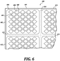
- FIG. 6 is a diagrammatical illustration of an embodiment of a plurality 600 of stencils provided on a larger substrate or backing sheet.
- a stencil 604 has an application surface having a plurality of first discontinuous subsurfaces as open holes 606 separated by a continuous second subsurface of ribs or strips 605 , where the plurality of discontinuous subsurfaces are arranged in a repeating pattern.
- the four stencil sections 602 , 610 , 612 , and 618 are connected through a common backing sheet 601 .
- the backing sheet is perforated along lines 614 and 616 to easily separate each stencil section 602 , 610 , 612 , and 618 from one another by manually tearing allowed by the perforation.
- the stencil section 602 includes the stencil 604 adhered to the backing sheet 601 via an adhesive.
- the stencil 604 is entirely included within the boundaries delineated by the perforated lines 614 and 616 .
- the stencil 604 is cut into a pattern including similar open hole shapes 606 by cutting along lines 608 , leaving strips 605 of material. Cutting along lines 608 will cut through the stencil 604 sheet material, but the cuts 608 are not so deep as to cut the backing sheet 601 .
- the backing sheet 601 is coated with a waxy surface that allows peeling the stencil 604 off the backing sheet and leaving the cut patterns 606 adhered to the backing sheet. The result is a stencil 604 having an adhesive on one major side with a plurality of open spaces.
- FIG. 7 illustrates an embodiment of a stamping applicator 700 .
- the stamp 704 has an application surface having a plurality of first discontinuous subsurfaces as protrusions 706 separated by a continuous second subsurface of grooves 708 , where the plurality of discontinuous subsurfaces are arranged in a repeating pattern.
- Stamping applicator 700 includes a handle 701 connected to a roller stamp 704 on both ends thereof via the use of two arms 702 and 703 .
- Roller stamp 704 has a generally cylindrical shape, but with a decreasing diameter from the center of the roller stamp 704 toward the ends.
- the roller stamp 704 can have a constant diameter.
- Roller stamp 704 is allowed to roll over surfaces.
- roller stamp 704 can include a hollow center and the arms 702 and 703 only partly engage the hollow center by the used of two nubs or pins inserted only partly on either side of the roller stamp 704 . This would allow replacing the roller stamp 704 by spreading the arms 702 and 703 apart, and withdrawing the roller stamp 704 .
- the ends of the roller stamp 704 can be provided with the nubs or pins which are inserted into corresponding hubs on either arm 702 , 703 .
- the design of the roller stamp 704 allows for rolling over areas on the skin on which a skin composition is desired to be applied.
- roller stamp 704 is made from an absorbent material, such as foam.
- a foam can absorb a composition and replenish the outer surface of the roller.
- the deep cut lines on the roller stamp 704 store composition for replenishing the outer surface.
- roller stamp 704 is made from a hard plastic.
- the roller stamp 704 is made from a metal.
- a metal roller stamp 704 has an advantage in that the metal can be actively heated.
- roller stamp 704 includes a geometric pattern in order to produce a discontinuous film on the skin surface.
- the roller stamp 704 includes diamond shapes 706 placed over the entire circumference from end to end of the roller stamp 704 .
- Individual diamond shapes 706 are produced, for example, by cutting deep notched continuous lines 708 in a criss-cross pattern into the roller stamp 704 material leaving behind the raised surfaces as the diamond shapes 706 .
- other embodiments of the roller stamp 704 can include any other shapes as disclosed herein for stamp applicators.
- FIGS. 8, 9, 10, and 11 show further embodiments of a stamp applicator.
- the stamp applicators 710 , 810 and 910 will be described hereinafter simultaneously, the elements common to the three embodiments being designated by the same reference numerals.
- the stamp applicator 710 , 810 , 910 comprises: a handle 712 , 812 , 912 ; a stamp roller 714 ; and a applicator 716 , 816 , 916 for electrically heating the stamp roller 714 .
- the roller 714 of the stamp applicator 910 is not shown in FIG. 10 .
- the handle 712 , 812 , 912 has a main portion 718 , 818 , 918 and two arms 720 . In FIG. 10 , the arms 20 of the handle 912 are not shown and the main portion 918 is partially shown.
- the main portion 718 , 818 , 918 extends substantially along a first axis 722 .
- a first end of said main portion is extended by said two arms 720 , which deviate from each other along the first axis 722 and then curve towards each other, in a plane comprising said first axis.
- Each arm 720 has a free end 724 , the two free ends 724 being located at a distance from one another on a second axis 726 .
- the second axis 726 is substantially perpendicular to the first axis 722 .
- the handle 712 , 812 , 912 comprises an internal cavity 728 , 828 , 928 , which extends inside the main part 718 , 818 , 918 and each of the two arms 720 .
- the gripping handle 712 , 812 , 912 is made of an elastically deformable material, at least at the level of the arms 720 .
- said arms 720 are flexible so as to allow the two free ends 724 to be separated and brought closer together.
- the handle 712 , 812 , 912 is made of thermoplastic polymer.
- the handle is made of metal or wood.
- the stamp roller 714 of the stamp applicator 710 , 810 , 910 is shown in longitudinal section in FIG. 11 .
- the stamp roller 714 has an outer surface 730 of substantially circular shape about a third axis 732 .
- the stamp roller 714 further comprises a through internal cavity 736 , extending along the third axis 732 .
- the stamp roller 714 is made of a good thermal conductive material and/or having a good thermal inertia, for example of stone or metal type.
- the stamp roller 714 is adapted to be removably connected to the handle 712 , 812 , 912 .
- the second 726 and third 732 axes are confused.
- FIG. 9 shows the stamp applicator 810 with the handle 812 and the stamp roller 714 in a dissociated configuration.
- the heating applicator 716 , 816 , 916 comprises a first part 740 , integral with the roller 714 , and a second part 742 , 842 , 942 , integral with the handle 712 , 812 , 912 .
- the first part 740 is housed in the internal through cavity 736 of the roll 714 .
- the first part 740 of the heating device 716 , 816 , 916 comprises at least one electric heating element 744 , for example an electrical resistance.
- the first part 40 comprises two electrical resistors 744 arranged facing the third axis 732 .
- the first part 740 further comprises an electrically insulating rod 746 , extending along the third axis 732 and serving as a support for the electrical resistors 744 .
- the first portion 740 further comprises two electrically conductive pads 748 .
- Each stud 748 is fixed to one end of the insulating rod 746 and electrically connected to one end of each of the electrical resistors 744 .
- a lateral surface of each stud 748 has a groove 750 receiving a gold seal 752 .
- each stud 748 comprises a first assembly element 754 .
- Said first assembly element 754 is intended for the mechanical connection of the roll 714 with the handle 712 , 812 , 912 , as well as at the electrical connection of the first portion 740 and the second portion 742 , 842 , 942 of the heater 716 , 816 , 916 .
- each first assembly member 754 has substantially the shape of a concave surface. Said concave surface notably has a shape of revolution around the third axis 732 .
- the first two assembly elements 754 are substantially identical.
- Each stud 748 and each first assembly element 754 is formed of an electrically conductive material such as a metal.
- the first portion 740 of the heating device further comprises two covers 758 electrically insulating.
- Each cap 758 is inserted at one end of the internal through-cavity 736 of the roller 714 .
- Each cap 758 comprises in particular a cylindrical portion 760 disposed around a stud 748 , at the level of the groove 750 .
- the covers 758 and the O-rings 752 provide a watertightness of the inner through cavity 736 and the electrical resistors 744 .
- the first portion 740 further comprises an additional O-ring disposed between each pad 748 and each corresponding cylindrical portion 760 .
- the cylindrical portion 760 further provides electrical insulation between the pad 748 and the roller 714 , especially in the case where the latter is made of metal.
- the first portion 740 of the heating device further comprises a fluid 762 of fat type, thermally conductive and electrically insulating.
- the fluid 762 fills the inner through-cavity 736 of the roller 714 around the electrical resistances 744 and the insulating rod 746 .
- the thermally conductive fluid 762 optimizes the heat transfer between the resistors 744 and the roller 714 .
- the second portion 742 , 842 , 942 of the heater 716 , 816 , 916 includes two second connecting members 770 , each of said second connecting members being disposed at the free end 724 of one of the arms 720 of the handle 712 , 812 , 912 .
- Each of the second connecting members 770 is intended to cooperate with a first connecting element 754 for the mechanical connection of the roller 714 with the handle 712 , 812 , 912 and for the electrical connection of the first portion 740 and the second portion 742 , 842 , 942 of the heater 716 , 816 , 916 .
- Each second assembly element 770 has the shape of a pin comprising an outer surface 772 , convex and of revolution.
- the outer surface 772 is able to fit into the concave surface of a first connecting element 754 .
- the outer surface 772 and the concave surface of the first connecting element 754 have a partial contact, so that minimize rotational friction.
- the outer surfaces 772 of the two second joining members 770 are substantially identical.
- the roller 714 can thus be assembled in both directions with the handle 712 , 812 , 912 .
- the second portion 742 , 842 , 942 of the heating device further comprises a member 774 , 874 , 974 for supplying the heating element 44 with power.
- the supply member 774 , 874 , 974 comprises in particular two conductive wires 776 , extending into the internal cavity 728 , 828 , 928 of the handle, at the arms 20 .
- a first end of each of the conductive wires 776 is connected to one of the second connecting elements 770 .
- the heating device 716 further comprises an electric cable 780 connected to a second end of the conductive wires 776 .
- the electrical cable 780 extends outside the main portion 718 of the handle gripper 712 from a second end of said main portion, opposite to the arms 720 .
- the electric cable is equipped with means (not shown) for connection to a low voltage electrical power source, USB type.
- the feed member 874 , 974 comprises an electric generator 882 , 982 disposed in the internal cavity 828 , 928 of the handle, at the main portion 818 , 918 .
- the electric generator 882 is a battery-type electric accumulator and the power supply member 874 further comprises a device 884 for connecting said electric accumulator to a source of electrical energy.
- the device 884 is for example a USB port.
- the electrical generator 882 is of nonrechargeable battery type, which improves the liquid tightness of the handle 812 , eliminating the openings giving access to the internal cavity 828 .
- the electric generator 982 is an induction rechargeable battery type electric accumulator.
- the supply member 874 further comprises an induction coil 986 disposed at a second end of the main portion 918 of the handle, opposite the arms 720 .
- the induction coil 986 is adapted to cooperate with an external charger (not shown) for recharging the electric accumulator 982 .
- Such an induction charging system is known in particular for devices of the electric toothbrush type, as described for example in the document WO2015147054. This embodiment allows non-contact reloading and good liquid sealing of the sleeve 912 .
- the power supply member 774 , 874 , 974 further comprises an electronic module (not shown) for regulating the power supply of the resistors 744 .
- This electronic module comprises, for example, a system for regulating the heating temperature. and/or a timer system. As an indication, a temperature of the outer surface 730 of the roll is limited to 50° C. by the electronic module.
- the power supply element 774 , 874 , 974 further comprises a switch 888 ( FIG. 2 ) enabling the power supply of the resistors 744 to be turned on and off.
- the stamp applicator 710 , 810 , 910 is part of an assembly 790 for the cutaneous application of a fluid cosmetic composition 792 ( FIG. 8 ).
- a cosmetic composition has a viscosity which decreases when its temperature increases. This is for example a wax-like facial mask composition.
- a method of mounting the stamp applicator 710 , 810 , 910 will now be described. It is considered that said stamp applicator is in the dissociated configuration of FIG. 9 .
- a user In order to assemble the handle 712 , 812 , 912 and the stamp roller 714 , a user assembles one of the second assembly members 770 said handle with one of the first assembly elements 754 of said roller. The user then exerts a mechanical force on the arms 720 of the handle in order to move them away from one another, in order to assemble the other second assembly element 770 with the other first assembly element 754 . the force on the arms 720 is then released and the stamp applicator 710 , 810 , 910 is in the assembled configuration of FIG. 1 .
- the complementary internal 756 and outer surfaces 772 of the connecting elements 754 , 770 form a pivot connection between the handle 712 , 812 , 912 and the roller 714 , around the second axis 726 .
- a distance between the second connecting elements 770 along the second axis 726 is slightly greater in the assembled configuration than in the dissociated configuration.
- the arms 720 exert a slight elastic compression on the roller 714 , which improves the electrical contact between the inner 756 and outer surfaces 772 .
- Said electrical contact makes it possible to form a closed electrical circuit between the first part 740 and the second part 742 , 842 , 942 of the heating device 716 , 816 , 916 , in particular by actuating the switch 888 .
- the switch 888 is operated to supply power to the resistors 744 .
- the temperature of the outer surface 730 of the roll increases.
- the roll 714 is then rolled against a surface 794 of the cosmetic composition 792 .
- Said composition softens on contact with the hot roll; the outer surface 730 is thus loaded in a fluid cosmetic composition.
- the roller 714 is then applied to the skin of a user, for example on the face.
- the stamp applicator 710 , 810 , 910 is moved so as to deposit cosmetic composition 792 on the skin of the user, by rolling the roller.
- the contact of the hot outer surface with the skin also provides a massaging effect.
- the cosmetic composition 792 then cools forming a film on the skin.
- the cosmetic composition 792 penetrates into the epidermis, the penetration being improved by the heat of the roller 714 .
- the cosmetic composition 792 is deposited manually on the skin, and then the hot roller 714 is applied.
- the hot stamp applicator 710 , 810 , 910 can also be used without a cosmetic composition, to stamp the face or another part of the body.
- the handle 712 , 812 , 912 and the stamp roller 714 are dissociated by a method that is the reverse of the above described method of assembly. If necessary, the tightness of the handle and the roller allows their cleaning with water without risk of short circuit.
- any stencil or stamp disclosed herein is provided in combination with a film forming composition, particularly skin-tightening compositions, as a combination package.
- a film forming composition particularly skin-tightening compositions
- a combination package for example, a consumer wishing to purchase a skin-tightening composition receives a stencil or a stamp for applying the composition together with the composition in the same package. This allows the matching of a particular film composition with the stencil or stamp that works most effectively with the composition.
- the disclosure relates to compositions for tightening the skin, said compositions comprising at least one thermoplastic elastomer, at least one adhesive polymer, and at least one filler, wherein the at least one thermoplastic elastomer has at least two glass transition temperatures (T g ).
- the compositions may be effective at reducing the appearance of skin imperfections.
- the compositions may improve the appearance of the skin by forming a film on the skin that has a Young Modulus greater than that of skin, and thus has the capability of tightening the skin.
- the term “tighten” means that the film contracts in a manner that skin has a tighter feel to the user, and that reduces the visual appearance of wrinkles in the skin.
- the disclosure relates to a skin-tightening film comprising at least one thermoplastic elastomer, at least one adhesive polymer, and at least one filler, wherein the at least one thermoplastic elastomer has at least two glass transition temperatures (Tg), wherein the film has a Young Modulus greater than about 500 kPa.
- Tg glass transition temperatures
- a film includes anionic copolymers based on methacrylic acid and methyl methacrylate in a random, block, or alternating configuration.
- a class of polymers known as organopolysiloxanes is disclosed as film forming polymers for application on the skin.
- organosiloxanes include polydimethylsiloxane (PDMS or Dimethicone).
- silicone polymers are copolymerized with other polymers, such as polyurethanes and ethylenically unsaturated monomers or polymers thereof.
- U.S. Pat. No. 8,277,791 discloses film forming polymers include silicone polyurethane polymers in combination with at least one elastomer selected from silicone gums, polyisobutylene, natural rubbers, and block-copolymer rubbers.
- the film composition is a skin-tightening composition.
- skin-tightening film compositions are disclosed in WO 2016/100742 and WO 2016/100690, both incorporated herein expressly by reference.
- a skin-tightening film composition includes an elastomer, an adhesive film forming polymer, and a filler.
- a skin-tightening composition includes at least one thermoplastic elastomer chosen from amorphous hydrocarbon block copolymers of styrene and monomers of hydrocarbon containing 2 to 5 carbon atoms and comprising one or two ethylenic unsaturations, and having a first T g below about 0° C., and a second T g greater than about 25° C.; at least one adhesive film-forming polymer chosen from polymer particles of C 1 -C 4 alkyl(methacrylate)polymer, stabilized in a nonaqueous dispersion; and at least one filler.
- thermoplastic elastomer chosen from amorphous hydrocarbon block copolymers of styrene and monomers of hydrocarbon containing 2 to 5 carbon atoms and comprising one or two ethylenic unsaturations, and having a first T g below about 0° C., and a second T g greater than about 25° C.
- the thermoplastic elastomer includes one or more styrene blocks and one or more blocks of units selected from butadiene, ethylene, propylene, butylene, isoprene, or mixtures thereof.
- the thermoplastic elastomer is a diblock copolymer chosen from styrene-ethylene/propylene copolymers, styrene-ethylene/butadiene copolymers, styrene-ethylene/butylene copolymers, styrene-butadiene, or styrene-isoprene copolymers; a triblock copolymer chosen from styrene-ethylene/propylene-styrene copolymers, styrene-ethylene/butadiene-styrene copolymers, copolymers of styrene-isoprene-styrene, or copolymers of styrene-iso
- adhesive polymers include C 1 -C 4 alkyl (meth)acrylate and ethylenically unsaturated acid monomer of C 1 -C 4 alkyl(methacrylate) polymer in an oil dispersion.
- the C 1 -C 4 alkyl(methacrylate)polymer is chosen from methyl(meth)acrylate, ethyl (meth)acrylate, n-propyl (meth)acrylate, isopropyl (meth)acrylate, n-butyl (meth)acrylate and tert-butyl (meth)acrylate polymers.
- the oil is a hydrocarbon based oil of up to 40 carbon atoms, such as isododecane.
- the filler is chosen from silica particles, hydrophobic silica aerogel particles, or aerogel particles of hydrophobic silica surface-modified with trimethylsilyl groups.
- film-forming compositions include volatile organic solvents, volatile hydrocarbon-based oils, or volatile silicone oils.
- the solvent is chosen from branched C 8 to C 16 alkanes, C 8 to C 16 isoalkanes, isododecane, isodecane, isohexadecane, octamethyltetrasiloxane, decamethylcyclo-pentasiloxane, dodecamethylcyclohexasiloxane, heptamethyloctyltrisiloxane, hexamethyldisiloxane, decamethyltetrasiloxane, dodecamethylpentasiloxane, and mixtures thereof.
- silicone elastomers are chosen from silicone crosspolymers, such as dimethicone crosspolymers, dispersed in at least one oil.
- a film composition is disclosed in U.S. application Ser. Nos. 15/087,115 and 15/094,259, entitled, “Systems and Methods for Improving the Appearance of the Skin” and “Compositions for Removing Cosmetic Films,” both are incorporated herein expressly by reference.
- a film composition includes one or more thermoplastic elastomers chosen from amorphous hydrocarbon block copolymers of styrene and monomers of hydrocarbon containing 2 to 5 carbon atoms and having one or two ethylenic unsaturations, and having a first T g (glass transition temperature) below about 0° C., and a second T g greater than about 25° C.; one or more adhesive film-forming polymers chosen from polymer particles of C 1 -C 4 alkyl(methacrylate)polymer, stabilized in a non-aqueous dispersion; and at least one filler; and a cosmetic composition for making up the skin, comprising at least one organic pigment and optionally at least one volatile solvent.
- thermoplastic elastomers chosen from amorphous hydrocarbon block copolymers of styrene and monomers of hydrocarbon containing 2 to 5 carbon atoms and having one or two ethylenic unsaturations, and having a first T g (glass transition temperature
- the cosmetic composition for making up the skin includes organic pigments chosen from nitroso, nitro, azo, xanthene, pyrene, quinoline, anthraquinone, triphenylmethane, fluorane, phthalocyanin, metal complex, isoindolinone, isoindoline, quinacridone, perinone, perylene, diketopyrrolopyrrole, indigo, thioindigo, dioxazine, triphenylmethane and quinophthalone compounds.
- the film compositions include any number of additional ingredients depending on the purpose of the film.
- the film includes one or more cosmetic ingredients selected from humectants emollients, moisturizers, skin-tightening ingredients, anti-wrinkle ingredients, concealers, matte finishing agents, pigments, colorants, proteins, anti-oxidants, bronzers, chelating agents, emulsifiers, ultraviolet (UV) absorbing agents, oil absorbing agents, anti-foam agents, anti-tack agents, thickeners, fragrances, preservatives, anti-microbials, fungistats, neutralizing agents, vitamins, plasticizers, cohesion agents, basifying and acidifying agents, fillers, solvents, and combinations thereof.
- humectants emollients selected from humectants emollients, moisturizers, skin-tightening ingredients, anti-wrinkle ingredients, concealers, matte finishing agents, pigments, colorants, proteins, anti-oxidants, bronzers, chel
- a film is a film that is adhered to facial features, including around the eyes, lips, cheeks, forehead, neck area. In an embodiment, a film is a film that is adhered on the skin.
- a film is a skin-tightening film.
- a film is a long wearing film, also known as a long lasting film.
- a long wearing or long lasting film is any film that is worn for up to or more than 10 minutes.
- a long wearing film is any film that is worn for up to or more than 20 minutes.
- a long wearing film is any film that is worn for up to or more than 30 minutes.
- a long wearing film is any film that is worn for up to or more than 1 hour.
- a long wearing film is any film that is worn for up to or more than 2 hours.
- a long wearing film is any film that is worn for up to or more than 4 hours.
- a long wearing film is any film that is worn for up to or more than 6 hours. In an embodiment, a long wearing film is any film that is worn for up to or more than 12 hours. In an embodiment, a long wearing film is any film that is worn for up to or more than 24 hours.
- the skin-tightening compositions comprise from 0.1 to 20% by weight of at least one tensioning agent, with respect to the total weight of the composition, and at least one dispersion in a liquid fatty phase of solid particles of a grafted ethylenic polymer, as disclosed in U.S. 2007/0224158.
- the tensioning agent can be chosen in particular from: a) synthetic polymers; b) polymers of natural origin; c) mixed silicates; d) wax microparticles; e) colloidal particles of inorganic fillers; and the mixtures of these.
- the synthetic polymers which can be used as tensioning agent can be chosen from: polyurethane polymers and copolymers; acrylic polymers and copolymers; polymers of sulphoisophthalic acid; grafted silicone polymers; water-soluble or water-dispersible polymers comprising water-soluble or water-dispersible units and LCST units; non-elastomeric and water-insoluble film-forming linear ethylenic block polymers exhibiting a dynamic storage modulus E′ at 1 Hz and at 22° C. of greater than 200 MPa; a dispersion in a liquid fatty phase of solid particles of a grafted ethylenic polymer exhibiting a glass transition temperature of greater than 40° C., and mixtures of these.
- tensioning agents which can be used comprise microdispersions of wax particles. They are dispersions of particles having a diameter generally of less than 5 ⁇ m or better still of less than 0.5 ⁇ m and composed essentially of a wax or of a mixture of waxes chosen, for example, from carnauba, candelilla or alfa waxes.
- US 2017/0216185 describes a skin-tightening test as follows.
- the test consists in comparing, in vitro, the tightening power of the polymer to be evaluated, with respect to a reference tightening polymer: Hybridur®875 polymer dispersion from Air Products (40% by weight aqueous dispersion of particles of an interpenetrated network of polyurethane and acrylic polymers).
- the polymer to be evaluated is deposited on a nitrile rubber strip cut from a glove sold under the reference Safeskin Nitrile Criticial No. 038846 by Dominique Dutscher SA, with a surface area of 3.5 cm 2 stretched taut beforehand on a support.
- An aqueous solution containing the polymer to be evaluated is thus deposited on the elastomer strip, by depositing 1.8 mg (as dry matter) of polymer.
- the tightening effect obtained according to the protocol described above, of polymers can be measured.
- the resistance to water of the tightening effect can also be evaluated by immersing the rubber strips treated with the polymer to be evaluated in water at ambient temperature (25° C.) for 10 minutes, followed by evaluating the tightening effect after drying for 1 hour.
- FIG. 12 is a diagrammatical illustration of a combination of a skin-tightening composition in a container 1202 and a stamp 1204 provided as a kit or unit 1200 .
- the container 1202 is any jar, tube, or other container suitable to contain a skin-tightening composition.
- the stamp 1204 is shown only as an example of an applicator, and is any suitable stamp or stencil disclosed herein.
- the container 1202 and applicator 1204 are held by shrink-wrap 1206 , for example. However, other suitable packaging is used to hold the applicator 1204 to the container 1202 .
- FIG. 13 is a diagrammatical illustration of a combination of a skin-tightening composition in a container 1304 and a stencil 1306 provided as a kit or unit 1300 .
- the container 1306 is any jar, tube, or other container suitable to contain a skin-tightening composition.
- the stencil 1306 is shown only as an example of an applicator, and is any suitable stamp or stencil disclosed herein.
- the container 1304 and applicator 1306 are held by molded plastic packaging 1302 , for example. However, other suitable packaging is used to hold the applicator 1302 to the container 1304 .
- a combination comprises a skin-tightening composition 108 , 210 and an applicator 104 , 202 , 400 , 500 , 604 , 700 configured to apply the skin-tightening composition in a discontinuous manner
- the applicator comprises an application surface having a plurality of first discontinuous subsurfaces 106 , 204 , 404 , 503 , 606 , 706 separated by a continuous second subsurface 110 , 206 , 405 , 502 , 605 , 708 where the plurality of discontinuous subsurfaces are arranged in a repeating pattern; and a skin-tightening composition.
- the first subsurfaces are open spaces 106 , 503 , 606 and the second subsurface forms ribs or strips 110 , 502 , 605 between the open spaces.
- the open spaces 106 , 502 , 605 have a non-isometric shape in the length and width dimensions.
- the open spaces 106 , 502 , 605 have diamond, square, rectangular, or any other polygon shape in the length and width dimension.
- the open spaces 106 , 502 , 605 have more than one shape.
- the open spaces 106 , 502 , 605 have more than one size.
- the skin-tightening composition 108 , 210 is provided in a container 1202 , 1212 , and the applicator 104 , 202 , 400 , 500 , 604 , 700 and skin-tightening composition are provided as a unit 1200 , 1210 .
- the skin-tightening composition 108 , 210 is selected from the group consisting of: anionic copolymers based on methacrylic acid and methyl methacrylate in a random, block, or alternating configuration, organopolysiloxanes, silicone-urethane copolymers, ethylenically unsaturated polycarbosiloxanes, silicone-urethane copolymers and an elastomer, an elastomer, an adhesive polymer, and a filler, and wax microparticles
- the combination comprises a stencil 104 , 500 , 604 including a material having a first and second major surface forming opposite sides of the material, wherein the first and second surfaces are separated by a thickness of the material with open spaces 106 , 503 , 606 in the material that traverse the material from the first major surface to the second major surface, wherein a majority of the open spaces have a similar shape to create a repeating pattern of open spaces along a length dimension and a width dimension of the material, and wherein the maximum average size of an open space in either a length dimension or width dimension is from 20 microns to 150 microns.
- the stencil 104 , 500 , 604 is a sheet or a mesh of filaments.
- the stencil 604 has an adhesive on one of the first or second major surfaces.
- the stencil 604 has a backing sheet 601 to which the stencil is adhered.
- the first subsurfaces are protrusions 204 , 404 , 706 and the second subsurface forms grooves 206 , 405 , 708 in between the first subsurfaces.
- outward facing surfaces of the distal ends of the protrusions 204 , 404 , 706 have a non-isometric shape in the length and width dimensions.
- outward facing surfaces of the distal ends of the protrusions 204 , 404 , 706 have a diamond, square, rectangular, or any other polygon shape in the length and width dimension.
- outward facing surfaces of the distal ends of the protrusions 204 , 404 , 706 include more than one shape of outward facing surface.
- outward facing surfaces of the distal ends of the protrusions 204 , 404 , 706 include more than one size of outward facing surfaces.
- outward facing surfaces of the distal ends of the protrusions 204 , 404 , 706 lie along a planar surface.
- outward facing surfaces of the distal ends of the protrusions 706 lie on a roller 704 .
- outward facing surfaces of the distal ends of the protrusions 404 collectively lie on a convex surface.
- outward facing surfaces of the distal ends of the protrusions 404 lie on a convex surface curving upwards from a center in all dimensions.
- outward facing surfaces of the distal ends of the protrusions 204 , 404 , 706 are flat.
- the combination comprises a stamp 202 , 400 , 700 having protrusions 204 , 404 , 706 extending from at least one surface, wherein outward facing surfaces of the protrusions collectively form a surface for stamping, a majority of the outward facing surfaces of the distal ends of the protrusions have a similar shape to create a repeating pattern along a length dimension and a width dimension, and wherein the maximum average size of the outward facing surface area of the distal ends of the protrusions in either a length dimension or width dimension is from 20 microns to 150 microns.
- a method of applying a skin-tightening composition 108 comprises placing a stencil 104 , 500 , 604 on a skin area 102 , wherein the stencil includes a material having a first and second major surface forming opposite sides of the material, wherein the first and second surfaces are separated by a thickness of the material with open spaces in the material that traverse the material from the first major surface to the second major surface, wherein a majority of the open spaces have a similar shape to create a repeating pattern of open spaces along a length dimension and a width dimension of the material, and wherein the maximum average size of an open space in either a length dimension or width dimension is from 20 microns to 150 microns; applying a skin-tightening composition to the stencil while on the skin area; and removing the stencil from the skin area that leaves a patterned skin-tightening composition on the skin area.
- a method of applying a skin-tightening composition 210 comprises providing a stamp 202 , 400 , 700 having protrusions 204 , 404 , 706 extending from at least one surface 206 , 405 , 708 wherein outward facing surfaces of the protrusions collectively form a surface for stamping, a majority of the outward facing surfaces of the distal ends of the protrusions have a similar shape to create a repeating pattern along a length dimension and a width dimension, and wherein the maximum average size of the outward facing surface area of the distal ends of the protrusions in either a length dimension or width dimension is from 20 microns to 150 microns; applying a skin-tightening composition 210 at least on the outward facing surfaces of the protrusions and bringing the skin-tightening composition on the stamp in contact with a skin area; and withdrawing the stamp and leaving a patterned skin-tightening composition on the skin area.
Abstract
Description
Claims (10)
Priority Applications (1)
| Application Number | Priority Date | Filing Date | Title |
|---|---|---|---|
| US15/965,647 US11399618B2 (en) | 2018-04-27 | 2018-04-27 | Methods and applicators for applying skin-tightening film products |
Applications Claiming Priority (1)
| Application Number | Priority Date | Filing Date | Title |
|---|---|---|---|
| US15/965,647 US11399618B2 (en) | 2018-04-27 | 2018-04-27 | Methods and applicators for applying skin-tightening film products |
Publications (2)
| Publication Number | Publication Date |
|---|---|
| US20190328111A1 US20190328111A1 (en) | 2019-10-31 |
| US11399618B2 true US11399618B2 (en) | 2022-08-02 |
Family
ID=68291760
Family Applications (1)
| Application Number | Title | Priority Date | Filing Date |
|---|---|---|---|
| US15/965,647 Active 2039-04-20 US11399618B2 (en) | 2018-04-27 | 2018-04-27 | Methods and applicators for applying skin-tightening film products |
Country Status (1)
| Country | Link |
|---|---|
| US (1) | US11399618B2 (en) |
Families Citing this family (1)
| Publication number | Priority date | Publication date | Assignee | Title |
|---|---|---|---|---|
| US20210000703A1 (en) * | 2019-07-03 | 2021-01-07 | HCT Group Holdings Limited | Multiple durometer cosmetic pad |
Citations (20)
| Publication number | Priority date | Publication date | Assignee | Title |
|---|---|---|---|---|
| EP0839009A1 (en) | 1995-07-18 | 1998-05-06 | Seb S.A. | Wax epilation apparatus provided with an applicator roll having substantially circular grooves |
| US6315482B1 (en) * | 1998-11-04 | 2001-11-13 | The Procter & Gamble Company | Applicator for applying and distributing substances to target surfaces |
| US6336763B1 (en) * | 1998-10-07 | 2002-01-08 | Colgate-Palmolive Company | Applicator for flowable substances |
| EP1204397A1 (en) | 1999-08-18 | 2002-05-15 | The Procter & Gamble Company | Discontinuous films for skin care compositions |
| EP1204399A2 (en) | 1999-08-18 | 2002-05-15 | The Procter & Gamble Company | Wear resistant topical compositions having improved feel |
| US6558682B2 (en) | 1999-08-18 | 2003-05-06 | The Procter & Gamble Company | Discontinuous films from skin care compositions |
| US20070224158A1 (en) | 2004-03-19 | 2007-09-27 | L'oreal | Method for the Cosmetic Treatment of Wrinkled Skin Using a Cosmetic Composition Containing a Tightening Agent and a Dispersion of Solid Particles of a Grafted Acrylic polymer |
| US20090032054A1 (en) * | 2007-08-01 | 2009-02-05 | Griffiths Catholyn T | Cosmetic applicator and method of making |
| US20090197054A1 (en) * | 2008-02-06 | 2009-08-06 | Nano Terra Inc. | Stencils With Removable Backings for Forming Micron-Sized Features on Surfaces and Methods of Making and Using the Same |
| US20110076448A1 (en) * | 2009-08-21 | 2011-03-31 | Nano Terra Inc. | Methods for Patterning Substrates Using Heterogeneous Stamps and Stencils and Methods of Making the Stamps and Stencils |
| US20110129956A1 (en) * | 2008-04-18 | 2011-06-02 | 1366 Technologies Inc. | Wedge imprint patterning of irregular surface |
| US20110280647A1 (en) * | 2010-02-13 | 2011-11-17 | David Edward Wilson | Package For Applying a Personal Care Product |
| US8277791B2 (en) | 2007-06-06 | 2012-10-02 | Avon Products, Inc. | Cosmetic compositions having improved transfer resistance |
| US20140286687A1 (en) * | 2011-11-17 | 2014-09-25 | Bb3 B.V. | Method for accurately depositing a relatively small amount of a lip product on an applicator and the applicator containing said lip product |
| CN104523478A (en) | 2014-12-05 | 2015-04-22 | 广东丸美生物技术股份有限公司 | Skin-care matrix with instant skin-tightening effects and its preparation method and use |
| US9050474B2 (en) | 2009-11-10 | 2015-06-09 | Avon Products, Inc | Transfer resistant cosmetic |
| WO2015147054A1 (en) | 2014-03-28 | 2015-10-01 | サンスター株式会社 | Electrically driven toothbrush |
| US20160128912A1 (en) * | 2014-11-10 | 2016-05-12 | The Procter & Gamble Company | Personal Care Compositions and Hangers |
| WO2016100742A1 (en) | 2014-12-18 | 2016-06-23 | L'oreal | Compositions and methods for improving the appearance of the skin |
| US20170216185A1 (en) | 2014-09-30 | 2017-08-03 | L'oreal | Acrylic polymer of maleic anhydride and use thereof in cosmetics |
-
2018
- 2018-04-27 US US15/965,647 patent/US11399618B2/en active Active
Patent Citations (21)
| Publication number | Priority date | Publication date | Assignee | Title |
|---|---|---|---|---|
| EP0839009A1 (en) | 1995-07-18 | 1998-05-06 | Seb S.A. | Wax epilation apparatus provided with an applicator roll having substantially circular grooves |
| US6336763B1 (en) * | 1998-10-07 | 2002-01-08 | Colgate-Palmolive Company | Applicator for flowable substances |
| US6315482B1 (en) * | 1998-11-04 | 2001-11-13 | The Procter & Gamble Company | Applicator for applying and distributing substances to target surfaces |
| EP1204397A1 (en) | 1999-08-18 | 2002-05-15 | The Procter & Gamble Company | Discontinuous films for skin care compositions |
| EP1204399A2 (en) | 1999-08-18 | 2002-05-15 | The Procter & Gamble Company | Wear resistant topical compositions having improved feel |
| US6558682B2 (en) | 1999-08-18 | 2003-05-06 | The Procter & Gamble Company | Discontinuous films from skin care compositions |
| US20070224158A1 (en) | 2004-03-19 | 2007-09-27 | L'oreal | Method for the Cosmetic Treatment of Wrinkled Skin Using a Cosmetic Composition Containing a Tightening Agent and a Dispersion of Solid Particles of a Grafted Acrylic polymer |
| US8277791B2 (en) | 2007-06-06 | 2012-10-02 | Avon Products, Inc. | Cosmetic compositions having improved transfer resistance |
| US20090032054A1 (en) * | 2007-08-01 | 2009-02-05 | Griffiths Catholyn T | Cosmetic applicator and method of making |
| US20090197054A1 (en) * | 2008-02-06 | 2009-08-06 | Nano Terra Inc. | Stencils With Removable Backings for Forming Micron-Sized Features on Surfaces and Methods of Making and Using the Same |
| US20110129956A1 (en) * | 2008-04-18 | 2011-06-02 | 1366 Technologies Inc. | Wedge imprint patterning of irregular surface |
| US20110076448A1 (en) * | 2009-08-21 | 2011-03-31 | Nano Terra Inc. | Methods for Patterning Substrates Using Heterogeneous Stamps and Stencils and Methods of Making the Stamps and Stencils |
| US9050474B2 (en) | 2009-11-10 | 2015-06-09 | Avon Products, Inc | Transfer resistant cosmetic |
| US20110280647A1 (en) * | 2010-02-13 | 2011-11-17 | David Edward Wilson | Package For Applying a Personal Care Product |
| US20140286687A1 (en) * | 2011-11-17 | 2014-09-25 | Bb3 B.V. | Method for accurately depositing a relatively small amount of a lip product on an applicator and the applicator containing said lip product |
| WO2015147054A1 (en) | 2014-03-28 | 2015-10-01 | サンスター株式会社 | Electrically driven toothbrush |
| US20170216185A1 (en) | 2014-09-30 | 2017-08-03 | L'oreal | Acrylic polymer of maleic anhydride and use thereof in cosmetics |
| US20160128912A1 (en) * | 2014-11-10 | 2016-05-12 | The Procter & Gamble Company | Personal Care Compositions and Hangers |
| CN104523478A (en) | 2014-12-05 | 2015-04-22 | 广东丸美生物技术股份有限公司 | Skin-care matrix with instant skin-tightening effects and its preparation method and use |
| WO2016100742A1 (en) | 2014-12-18 | 2016-06-23 | L'oreal | Compositions and methods for improving the appearance of the skin |
| WO2016100690A1 (en) | 2014-12-18 | 2016-06-23 | L'oreal | Compositions and methods for improving the appearance of the skin |
Non-Patent Citations (4)
| Title |
|---|
| Bing, Diamond Stencil Template—Bing Images, <https://www.bing.com/images/search?q=Diamond+Stencil+Template&FORM=IDINTS>, available as early as Oct. 18, 2017, retrieved Apr. 30, 2018, 1 page. |
| Cartlidge, Edwin. "New State of Matter Seen in Clay." Science, AAAS, Dec. 21, 2010, www.sciencemag.org/news/2010/12/new-state-matter-seen-clay#:˜:text=A%20gel%20is%20a%20liquid,pharmaceuticals%20to%20paints%20and%20cosmetics. (Year: 2010). * |
| Emma. "What Is Matrixyl? Aging Skin Wants to Know." SkincareRX, Thehut.com LTD, Sep. 28, 2018, www.skincarerx.com/blog/ingredients/matrixyl-aging-skin-wants-know/. (Year: 2018). * |
| Etsy, QuirkyCraftsShop, "Diamond Nail Stencils, Geometric Nail Stencil, DIY Nails," <https://www.etsy.com/fr/listing/289751065/diamant-a-ongles-pochoirs-pochoir-ongles >, available as early as Oct. 18, 2017, retrieved Apr. 27, 2018, 4 pages. |
Also Published As
| Publication number | Publication date |
|---|---|
| US20190328111A1 (en) | 2019-10-31 |
Similar Documents
| Publication | Publication Date | Title |
|---|---|---|
| JP6843020B2 (en) | Film manufacturing method | |
| JP5539215B2 (en) | Compositions and methods for dry application of mascara | |
| JP4661867B2 (en) | Hair composition | |
| RU2764130C2 (en) | Cosmetic device, kit containing this device, as well as methods for applying makeup | |
| JP6316495B1 (en) | Method for producing cosmetic coating | |
| WO2011121510A2 (en) | Device for the application of fibers to human keratinous fibers | |
| JP6509402B2 (en) | Composition for film formation | |
| KR20090113279A (en) | Make-up method and set for carrying out said method | |
| US20100239619A1 (en) | Semi-permanent color for application to the skin and applicators therefor | |
| EP3328226B1 (en) | Cosmetic treatment method | |
| JP2019523276A (en) | Makeup care system | |
| EP3379959A1 (en) | Assembly and process for moulding keratin fibres | |
| US11399618B2 (en) | Methods and applicators for applying skin-tightening film products | |
| TW202011929A (en) | Method for producing coating film | |
| JPWO2018194140A1 (en) | Method of producing coating and electrostatic spray apparatus | |
| JP2017525523A (en) | Keratin fiber cosmetic treatment | |
| US8257718B2 (en) | Apparatus and method for manufacture of cosmetic applicator | |
| TWI763826B (en) | Manufacturing method of cosmetic film | |
| EP1229810B1 (en) | A swab for make-up removal | |
| TW202014175A (en) | Method for producing wearable coating | |
| US20080159804A1 (en) | Cosmetic or pharmaceutical product and applicator for cosmetic or pharmaceutical powders or beads and method of use | |
| CA2899934A1 (en) | Applicator | |
| JP4346242B2 (en) | Sheet-like pack, method for producing the same and method for using the same | |
| TW200819084A (en) | Film dispenser | |
| KR20170012433A (en) | Cosmetic treatment of keratin fibres |
Legal Events
| Date | Code | Title | Description |
|---|---|---|---|
| FEPP | Fee payment procedure |
Free format text: ENTITY STATUS SET TO UNDISCOUNTED (ORIGINAL EVENT CODE: BIG.); ENTITY STATUS OF PATENT OWNER: LARGE ENTITY |
|
| STPP | Information on status: patent application and granting procedure in general |
Free format text: RESPONSE TO NON-FINAL OFFICE ACTION ENTERED AND FORWARDED TO EXAMINER |
|
| STPP | Information on status: patent application and granting procedure in general |
Free format text: FINAL REJECTION MAILED |
|
| STPP | Information on status: patent application and granting procedure in general |
Free format text: RESPONSE AFTER FINAL ACTION FORWARDED TO EXAMINER |
|
| STPP | Information on status: patent application and granting procedure in general |
Free format text: ADVISORY ACTION MAILED |
|
| STPP | Information on status: patent application and granting procedure in general |
Free format text: DOCKETED NEW CASE - READY FOR EXAMINATION |
|
| STPP | Information on status: patent application and granting procedure in general |
Free format text: NON FINAL ACTION MAILED |
|
| AS | Assignment |
Owner name: L'OREAL, FRANCE Free format text: ASSIGNMENT OF ASSIGNORS INTEREST;ASSIGNORS:FARRAN, ALEXANDRA JANE ELISA;BERNARD, ANNE-LAURE;PHAMDUY, THERESA;AND OTHERS;SIGNING DATES FROM 20181107 TO 20190520;REEL/FRAME:057884/0294 |
|
| STPP | Information on status: patent application and granting procedure in general |
Free format text: RESPONSE TO NON-FINAL OFFICE ACTION ENTERED AND FORWARDED TO EXAMINER |
|
| STPP | Information on status: patent application and granting procedure in general |
Free format text: NOTICE OF ALLOWANCE MAILED -- APPLICATION RECEIVED IN OFFICE OF PUBLICATIONS |
|
| STCF | Information on status: patent grant |
Free format text: PATENTED CASE |